Article

Using Domain-Specific Models to Facilitate Model-Based Systems-Engineering: Development Process Design Modeling with OPM and PROVE

Systems Engineering Research Initiative, Faculty of Engineering, Tel Aviv University, Tel Aviv 6997801, Israel
*
Author to whom correspondence should be addressed.
Appl. Sci. 2021, 11(4), 1532; https://doi.org/10.3390/app11041532
Submission received: 11 January 2021 / Revised: 4 February 2021 / Accepted: 5 February 2021 / Published: 8 February 2021

Abstract

:

Featured Application

Introducing domain-specific models can enhance the applicability of model-based systems engineering, as well as improve its rigor.

Abstract

Model-based Systems Engineering (MBSE) approaches are a step forward in the evolution of computer-aided engineering, and yet, they often incorporate deficiencies that may jeopardize their practical utility and usability, as well as the validity of the resulting models. We demonstrate how a domain-specific modeling approach can relieve some hurdles in adopting MBSE, and how it can be used in tandem with a general-purpose modeling approach to augment and introduce rigor to models. Specifically, we demonstrate the consequences of theoretical issues that were previously identified in Object Process Methodology and suggest an approach to solve them. We use a generalized case-study—derived from extensive process modeling in both academia and industry—to show that a domain-specific model can significantly relax the user’s modeling effort. This demonstration is based on two quantitative metrics: the number of representational elements and available modeling tactics. We discuss the contribution of our approach to model quality, particularly with respect to its rigor and communicability.

Graphical Abstract

1. Introduction

Model-based Systems Engineering (MBSE) approaches can be seen as a step forward in the evolution of computer-aided engineering, as they employ formalized, often standardized, models [1,2,3,4]. However, while MBSE is widely researched [3,5], its widespread industrial applicability remains limited and challenging [6,7,8,9]. This points to a gap in the theoretical understanding of MBSE as practiced.
MBSE significant benefits emerge from a comprehensive use across systems life cycle, where they serve as a “sole source of truth” [3]. However, there are technical challenges that need to be addressed to achieve this, including: detecting and managing inconsistencies between models (e.g., [10,11]); supporting the interoperability of modeling tools; and bridging the semantic gap between modeling languages used for different perspectives and their resulting models (e.g., [3,12,13]). The issue of bridging the semantic gap is so central that it enters the definition of the System Modeling Language (SysML) [14].
While trying to support systems engineering in a comprehensive manner, the richness and sophistication of engineering modeling-languages threaten their utility and wide usability. These characteristics also risk the models’ communicability, which is considered a fundamental motivation for using MBSE [15]. The ability of nontechnical stakeholders to understand models is one aspect of usability; and it has been addressed by developing storytelling capabilities [16] or by providing equivalent textual description to models [17].
Model quality issues could hinder the successful adoption of MBSE. Studies on this topic attempt to define what quality model means, how to manage models, and how to improve them [15,18,19]. One of the solution approaches is the use of domain specific modeling (DSM) [15]. (DSM can also stand for Design Structure Matrix, however, in the object-oriented community from which UML and SysML emerged, it refers to Domain Specific Modeling and as such it is used in this paper.) This proposed approach deals with an issue that is critical but receives less attention than others—the practice of MBSE, i.e., the process of using MBSE tools to produce models, which could be challenging [20]. Such process-related challenges are typically unquantifiable and transitory. These challenges are commonly only identifiable—limitedly and indirectly—through post-modeling analyses, surveys, or interviews (e.g., [5,6,7]). Two systematic literature reviews of MBSE-related modeling domains identified similar gaps. A review of state-of-the-art business process modeling maturity [20] found that publications on modeling process quality are rarer than those on modeling product quality (i.e., quality of the resulting model); the review found that conducting experiments is the dominant research method, focusing on the end-result quality. The review recognized that example-based studies rarely relate to semantic quality, and called for more research on semantics, proposing that it may contribute to aligning models with their domain of interest. Similarly, another review of factors influencing the understandability of process models criticized the prevalent approach of conducting experiments containing questionnaires that aim to capture subjective measures with respect to the resulting models [21].
In this study, we focus on aspects concerning the user-designer perspective, and particularly the rigorous, semantical design and interpretation of models and the usability of modeling approaches. These aspects constitute the foundation, which should be solid in order to support advanced implementation issues (such as interoperability).
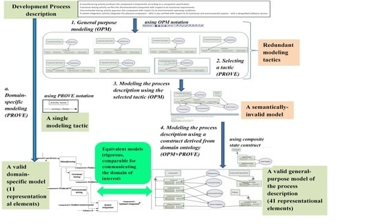
We offer a direct observation into some of the practitioners’ challenges as they emerge and show how they can be addressed. Specifically, we demonstrate usability issues of general-purpose modeling (GPM) and the use of domain-specific modeling (DSM) to overcome these issues. Two hypotheses are defined:
  • Using DSM can decrease the number of available modeling tactics, compared with GPM, with no loss of details in resulting models (i.e., the DSM and the GPM models contain the same information).
  • Using DSM can decrease the number of representational elements of the final model, compared with GPM, with no loss of details in resulting models.
We expect both hypotheses to be confirmed, thereby showing that DSM can relieve cognitive load in model-based design. First, in Section 2, we provide background regarding MBSE and the two modeling approaches that we use in our demonstration: the general-purpose Object Process Methodology (OPM) [17,22,23] and the domain-specific Process Oriented Viewpoint for Engineering (PROVE) [24,25]. While our ideas are demonstrated with these specific approaches, this paper is not about them, does not attempt to promote any of them. Furthermore, we claim that similar issues exist in different general-purpose approaches that could be addressed equally by corresponding use of domain-specific approaches. Consequently, we do not provide an extensive description of OPM or PROVE and refer readers to their respective references for further details. Our research plan is described in Section 3. Then, in Section 4, we present a process description, which is based on generalization of real-life, development-process situations in industry; and model it using OPM and PROVE. Finally, in Section 5, we discuss the approach demonstrated in the representative, applicative case study and its contribution to modeling theory and practice.

2. Background

2.1. Model-Based Systems Engineering (MBSE)

MBSE is “the formalized application of modeling principles, methods, languages, and tools to the entire lifecycle of large, complex, interdisciplinary, sociotechnical systems” [1]. MBSE is regarded as an approach to address the increasing complexity of systems in general and the complexity of their development, specifically. Some of the main features of MBSE identified as beneficial are enhancing communication between stakeholders; establishing shared understanding of relevant domains; and improving the capture and reuse of knowledge and information. Accordingly, MBSE can be viewed as a distributed cognition mechanism, allowing rigorous design and analysis of large amounts of data, using visual representations and common data repositories—established and maintained by relevant stakeholders—as a coherent, unambiguous digital model [1,26]. In a recent survey, the majority of participating practitioners credited improvement across almost all systems engineering tasks to the use of MBSE [5].
In general, MBSE solutions comprise two core components: (1) a methodology, providing the formal aspects of the model to be used as well as modeling concepts, methods, and a language; and (2) a software-based modeling tool implementing the methodology. While the essentials of MBSE are beyond the scope of this paper, we provide a brief introduction herein, and further discuss relevant aspects of MBSE throughout the paper, whenever required.
A modeling methodology may include concepts, methods, and a language—alternately, a notation or a representation. The concept and methods detail how to build a digital information model; while a modeling language dictates the representation of the model, typically using visual elements and their relationships as syntax. In what follows, we use the term methodology to refer to one or more of its constituents.
Achinstein emphasized four characteristics of models [27]: (1) they consist of a set of assumptions about some system; (2) they attribute mechanisms to the system, meant to explain exhibited properties; (3) they are an approximation useful for certain purposes; and (4) they are often developed on the basis of analogies between the represented system and some different system. In addition, the Bunge–Wand–Weber model stresses the importance of the ontological clarity of modeling language constructs, i.e., the clear association of a language construct with an ontological construct [28].
A practical methodology, therefore, is expected to refer to the relevant domain’s ontology (see, for example, [29]). Domain ontologies are considered important in defining and coordinating terminologies, concepts, and their relationships as well as in facilitating consistency and interoperability between different applications; and their effective use requires a well-designed language [12,30]. However, this is not always the case. Wand and Weber [31] identified that modeling language constructs are typically first created to represent software elements and not real-world elements; and called for assigning ontological meaning to modeling constructs. Specifically, Jørgensen asserted that the prominent Unified Modeling Language (UML) “is designed for software developers, not for end users” [32]. He also identified the mapping of system-oriented constructs of GPM languages to user-oriented and process-oriented concepts as a core challenge to which no general solution exists; and attributed the lack of a standardized approach to the wide range of process modeling approaches. Similarly, Bork et al. noted the absence of complete and consistent modeling specifications as a cause for the limited use and acceptance of modeling languages, as well as for the idiosyncratic nature of resulting models (which, in turn, reduces their comprehensibility and their reusability) [33]. In their survey of modeling language specifications, Bork et al. found that almost all the specifications use redundant notations. Further, modeling guidelines were found only in one out of the eleven surveyed specifications. These examples emphasize that modeling methodologies are often not designed with respect to domain ontologies.
A modeling software tool is an implementation of the methodology, providing a potential user with the ability to use some or all of the methodology, while taking into consideration further usability functions (some of which may not be related to modeling). While the modeling tool is out of the scope of this paper, we relate to relevant aspects as they emerge throughout.

2.2. Development Process Design (DPD)

DPD is a domain dedicated to the application of appropriate development approaches to realize engineered systems and products (e.g., [34,35]). A modeling methodology, implemented by a modeling tool, may be used for DPD, but this does not imply it is practically acceptable or that it supports the ontology of the creative design process [32,36]. The idiosyncrasy of resulting process models is a major issue in using GPM to address DPD in industry; in stark contrast to the role of MBSE as a communicable, formal model and to practitioners’ expectations from using models [7]. A prominent reason for this becomes obvious when one considers rich modeling languages such as SysML [37] and the Business Process Modeling and Notation (BPMN) [38] and their aforementioned redundancies. Process modelers can use the rich language as they wish, provided the predefined syntax is not violated. The modelers can freely approach the task with self-defined methods, and eventually produce a model that is unique in form, and typically incomparable with models made by others (perhaps even with previous models by the same modeler). A prominent example is a research that examined process modeling by experienced systems engineers using OPM [39]. The research showed wide diversity between the resulting models, even though the same textual description was used as the basis for modeling. Combining a GPM—such as OPM—with additional representations and with specialized modeling languages was suggested as means to improve MBSE state-of-the-art [13].
Domain specific models (DSM) may help to address the aforementioned concerns, providing a modeling approach that refers to a domain-of-interest and its ontology. Frank identified several relevant characteristics of DSM [40] that correspond with Wand and Weber’s guidelines for model design [28]: the ability to use domain-level concepts, rather than constructing them from scratch (as in GPM); the use of a domain-specific language, for promoting model integrity and quality; and a dedicated, typically visual, notation, for improving model clearness and comprehensibility. However, these statements remain theoretical, as no example that compares the DSM approach with the GPM approach was provided. Furthermore, an extensive, recent systematic literature review of ontology-based systems engineering called for combining GPM languages with ontology-related mechanisms [30].

2.3. Modeling Methodologies Used (OPM and PROVE)

In this paper, we use OPM to represent a GPM approach and PROVE as a DSM approach. We demonstrate some challenges of the modeling effort, and how they can be addressed—by reducing syntax and introducing domain ontology—to advance MBSE applicability and support its meaningful, beneficial use.
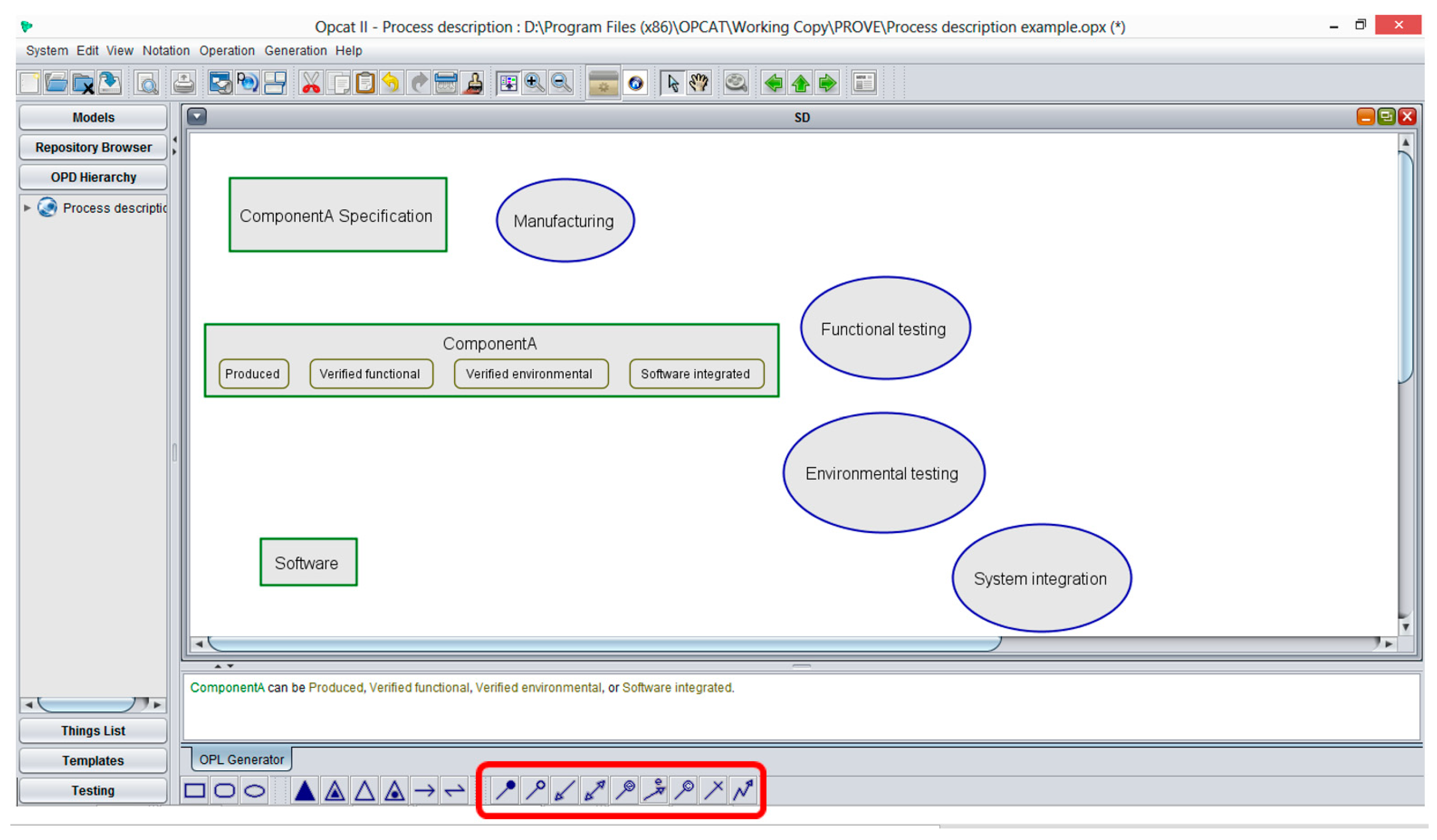
OPM is a leading conceptual modeling language and methodology for modeling systems. OPM modeling can be implemented using the OPCAT or OPCloud modeling tools. We continue by using OPCAT for this paper and note that similar results would be obtained by using OPCloud. OPM is specified in a formal specification [17,23]. Pertinent aspects of OPM will be explained in the context of their use, as it is both unrealistic and irrelevant to reproduce its specification here.
OPM has been suggested and demonstrated as a tool for constructing process models. Despite our efforts, we have yet to find well-documented guidelines or uses of OPM for concrete DPD; only theoretical, limited, or straightforward readings of conceptual models were found. Sharon et al. [41], for example, explicitly stated that they had used a simplified project model for describing an imaginary development project, specifically mentioning the lack of states in the model as one of the simplification aspects. Similarly, Li et al. only provided a straightforward reading of the V-Model (a well-known conceptual model for system development) [42].
Soffer et al. evaluated the appropriateness of OPM for modeling information systems requirements specifications, based on a theoretical framework derived from the Bunge-Wand-Weber model [43]. While the authors established that OPM is ontologically complete, they identified deficiencies with respect to its ontological clarity (construct overload, construct redundancy and construct excess). These theoretical deficiencies have yet to be addressed in the design of OPM. Specifically, as a follow-up to the research by Soffer et al., Wand and Weber suggested that future work should aim to provide empirical evidence of any impact that such deficiencies have on OPM users [31]. However, there is no work exploring the OPM deficiencies we summarized and their implications. In Section 4, we demonstrate how the said deficiencies of OPM hinder the use of MBSE for designing real-life development processes and risk MBSE objectives.
Unlike the established OPM, PROVE is a recently-introduced addition to the stock of modeling methodologies. PROVE is a DSM for DPD, designed based on DPD domain ontology [24]. As with OPM, pertinent aspects of PROVE will be explained in their context of use.
We chose OPM as the representative GPM due to several reasons. First, OPM is a state-of-the-art, standardized MBSE approach [
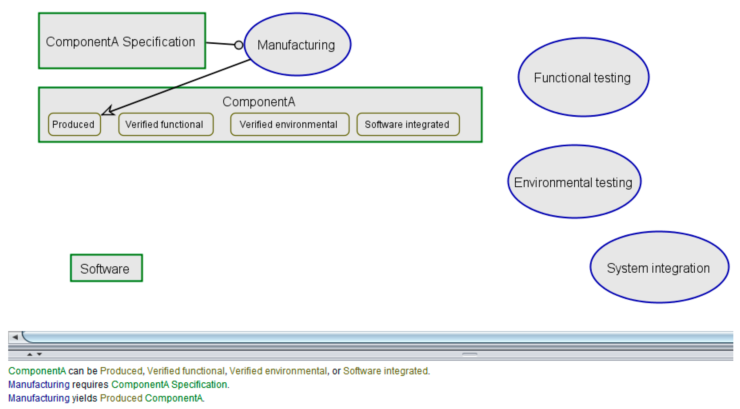
23]. Second, OPM’s notation is simpler compared with other GPM (such as SysML and BPMN), allowing us to communicate ideas more easily with the readers. Furthermore, an OPM diagram (OPD) is automatically translated into a natural-language description (OPL), which—we believe—can further facilitate the communication of our models and concepts with the readers.
We chose PROVE as the representative DSM due to two reasons: (1) PROVE’s core concepts are consistent with OPM [24]; thereby, allowing us to explicitly demonstrate how DSMs may contribute to state-of-the-art GPM; and (2) PROVE establishes a DPD ontology with concise notation, allowing us to communicate domain ideas easily with readers.

3. Research Plan

The research follows a case study methodology, including two cases. Nevertheless, these cases were carefully crafted as generalized cases, based on extensive process modeling in both academia and industry; and the cases designs avoid over-simplification. Our research is therefore representative of DPD modeling.
In the next section (Section 4) we demonstrate how GPM (OPM) can be cumbersome to use and how it can be enhanced using DSM (PROVE). This will lead to conclude that DSM can be used in conjunction with GPM to address the issues of usability discussed in the introduction. This demonstration describes the modeling of a partial process description extracted as a generalized case from real-life development plans. We present the case as an exercise in process description modeling. This is done in order to give readers a sense of the effort that is required in order to perform MBSE in industry; and establish that modeling complexity incorporates not only the complexity of the language but also manifestations of the modeling concepts and the modeling process. Eventually, such understandings should convince the reader not only of the value proposition of using DSMs, but—more importantly—that a careful, ontology-based approach is required for facilitating rigorous and meaningful use of MBSE for domain applications [30].
To simplify our demonstration, the challenge here is to model an existing process design, and not to design a process. This neutralizes aspects of process design, allowing us to focus exclusively on modeling aspects. Some “shortcuts” are made with respect to the process description and its modeling, in order to maintain a manageable scope that can be clear even to readers who are not domain experts. These “shortcuts”, however, do not result in any loss of generality; nor do they over-simplify practical aspects. Following the first case, we take an existing DSM process model and translate it to a rigorous GPM model. This serves to provide added evidence about the differences in model complexity between the approaches.
The first case study includes the following steps (Section 4.2, Section 4.3 and Section 4.4):
  • Model a process with GPM (e.g., OPM): we show the difficulty and cognitive load of using the GPM to model the process.
  • Model the process with GPM using insight from DSM (e.g., PROVE): we show how insight related to DSM ontology allows using selected GPM patterns to simplify modeling.
  • Model the process with DSM: we show how using a well-designed DSM methodology can simplify modeling considerably.
The second case study includes a single step (Section 4.5):
  • Take a model created with DSM and translate it to a GPM.
We define two quantitative metrics to establish our observations throughout the case studies: (1) the number of available modeling tactics during the modeling process, which is an indication of the cognitive load of the modeling process (e.g., selecting a modeling tactic that is semantically valid to the situation and model intent); (2) the number of representational elements of the final model, which is an indication of the cognitive load required to interpret and communicate the model, as well as an indication of the modeling effort itself (as each of these representational elements are typically created manually by the modeler; see, for example, [29], in which the complexity of modeling simple system characteristics is explicitly identified as a barrier for MBSE adoption). The latter metric is also an indication of model parsimony, which is a preferred model property [44]. Two hypotheses related to these metrics were articulated in the introduction.

4. Case Studies: Using DSM to Address GPM Limitations in DPD

4.1. The First Process Description

We are interested in modeling the process description of Table 1, which is an excerpt from a development effort scenario. This excerpt is based on occurrences observed in multiple real-life development efforts. Being common to several projects in which we were involved, this process description can be considered as a development method that can be incorporated into a larger process design. We note that this excerpt is not meant to be complete; specifically, additional artifacts are typically required for such scenarios (e.g., functional requirements specification, and environmental conditions specification). This incompleteness, however, does not affect our discussion. Keeping the process description to a minimum—while representing all of its components—allows us to communicate relevant aspects of process description modeling more clearly. A process description with more artifacts will require a larger process model, which is not easily communicable; and, in fact, does not contribute any new value to our discussion, which already addresses a fully featured representation of the process design from an engineering perspective. Finally, we would like to demonstrate the practical difficulty of using GPM. If we can demonstrate it on a seemingly simple and frequent process, this difficulty will be exacerbated when dealing with large-scale models. A practitioner is the one that has to deal with the details of modeling and this process exemplifies such work.

4.2. Modeling a Process with GPM (OPM)

We now model the process description of Table 1 using OPM. (Disclaimer: the approach presented in this section is not the only possible OPM modeling approach. Yet, we believe it is fairly representative of the modeling effort using OPM (if anything, we believe the approach we present is simpler compared with others).) OPM identifies object, process, and state as three fundamental entity types. Table 2 presents the analysis of the process description for OPM modeling.
We create the identified elements in the OPM tool OPCAT, shown in Figure 1. The modeling toolbox is found at the bottom of the screen; a navigation panel is on the left; the OPD diagram—featuring the elements—is centered; and the corresponding OPL natural-language description is below the OPD. Elements are created by selecting the appropriate tools from the toolbox. It takes 4 steps to create the 4 processes, 3 additional steps to create the objects. States are added to an existing object, by performing 4 additional steps.
So far, modeling did not require any cognitively demanding decision making, and was rather straightforward. Now, we try to establish the process description flow. The links that are relevant for connecting Objects and Processes appear in the rightmost batch of the toolbox (enclosed using red outline in Figure 1). There are nine link-types: seven of them can be used to connect objects and processes, and five of them can be used to connect states and processes. These representational elements are directional, i.e., they need to be used in the right direction (e.g., either from process to object, or from object to process). This is where decision-making becomes a necessity, and the process modeling itself—and not process design—begins to demand cognitive effort. (We remind readers that this is true to the modeling approach we chose to implement. In other implementations, a demanding cognitive effort concerning modeling may appear even earlier. For example, if one would have chosen to create objects and processes, connect them, and only then create states for the objects and use them, this would have required an increased effort.) This is also where unique, idiosyncratic modeling preferences start to affect the resulting model.
Figure 2, Figure 3, Figure 4, Figure 5, Figure 6, Figure 7 and Figure 8 show seven modeling alternatives that are all correct with respect to OPM syntax (but not necessarily with the semantics of the process description). The OPL descriptions may help readers to reveal the nuances between the modeling alternatives, each employing a different scheme of using OPM notation and concepts. The first three present direct connectivity between object and process, using the different types of links available in OPM, to connect such model elements: in Figure 2, the process (Manufacturing) “requires” an object (ComponentA Specification), using OPM’s instrument link, and “yields” another object (ComponentA), using OPM’s result link; in Figure 3, the process “occurs if” an object is “in existent”, using OPM’s instrument condition link and “yields” another object (using the result link); in Figure 4, the process “consumes” an object, using OPM’s consumption link, and “yields” another (using the result link).
The next three alternatives are represented in Figure 5, Figure 6 and Figure 7—each being variation on Figure 2, Figure 3 and Figure 4, respectively—employ links between a process and its resulting object’s state, i.e., the process now yields an object (ComponentA) in a specific state (Produced), using the result link with a state element as its target (as opposed to its use in Figure 2, Figure 3 and Figure 4, in which its target is an object element). The last alternative (Figure 8) shows a more rigorous alternative, with the process only using objects in defined states for both outputs and inputs, i.e., the process now “requires” an object in a specific state (instrument link from state element associated with an object element to the process; and since the state designation of the input is not specified explicitly, it is denoted as “0”). The multiplicity introduced by these alternatives clearly demonstrates that OPM is lacking with respect to ontological clarity, in accordance with the theoretical findings by Soffer et al. [43]. Specifically, OPM allows modeling the creation of an object (as an ontological concept) by using the result-link from a process to the object (the first three alternatives, in which “Manufacturing yields ComponentA”) or by using the result-link from a process to a specific state of the object (last four alternatives, in which “Manufacturing yields Produced ComponentA”). Similarly, the ontological concept of using of objects by processes is allowed in the form of an instrument-link from object to process (Figure 2) or from state to process (Figure 8), or in the form of a consumption-link (Figure 4); we note that while the first two options are semantically valid with respect to the process description, the third option is not. Modeling using more than one of the available alternatives can result in inconsistent and incomparable model segments; and it is, therefore, expected from the user-designer to select and use a single alternative, in order to produce a coherent, rigorous model.

4.3. Modeling a Process with GPM Considering Insight from DSM

We can use the DPD ontology of PROVE to make a significant reduction of the cognitive modeling problem (of selecting a single modeling tactic from the various alternatives). PROVE’s domain ontology allows a process only to use or deliver objects (in PROVE’s terminology these are called artifacts; and we use the terms interchangeably), and not to consume objects. Furthermore, its ontology expects artifact states to be explicitly mentioned. Accordingly, we limit our use of OPM links to the instrument-link used from a state to a process, to depict process dependency in an object with a specific state; and to the result-link used from a process to a delivered object’s state, to depict a process yielding an object in a specific state. We note that this exercises two different OPM link types. This approach is based on the modeling alternative presented in Figure 8; the result of consistently applying this alternative as a modeling pattern to the entire process description is shown in Figure 9. Obviously, modeling the entire process description to achieve this result would have been considerably more demanding without selecting an ontology-informed tactic.
At first glance, the diagram in Figure 9 presents a reasonable model of the process description. However, this model is semantically incorrect: according to OPM, an object is allowed to be in one state at any given time; and therefore, the “System integration” process—which according to the process description requires ComponentA to be “Verified functional” as well as “Verified environmental”—is interpreted in the OPL description as “requires either Verified environmental ComponentA or Verified functional ComponentA”. That is an incorrect formal model of the given process design! This conflict between OPM’s visual representation and OPM’s methodology suggests that OPM is insufficient to model our domain.
We look for the solution in the DPD domain ontology of PROVE, taking the following approach to solve the above conflict. PROVE’s ontology views states as attributes, allowing for multiple attributes to be exhibited by the object simultaneously—manifesting another DPD concept defined by PROVE: the “composite state” mechanism. The composite state of an object is considered the set of all its attributes (alternately, the “elemental states”); and it embeds the information about the object—throughout the development process—into the object itself, using these attributes and in agreement with object-oriented modeling paradigms. Accordingly, instead of mapping a designated object state to the OPM element-type “state”, we map it to a more elaborate modeling construct, which is to be associated with the OPM object as an attribute. The result, as projected directly on the aforementioned conflict, is shown in Figure 10. It shows that the relevant model segment is now interpreted (in the OPL description) as “System integration requires Achieved Verified environmental and Achieved Verified functional”, with the two attributes being “exhibited” by ComponentA (A DPD domain-specific representation of the OPM text may be used to offer a more “user-friendly” statement to the modeler, e.g., “System integration requires Achieved Verified environmental ComponentA and Achieved Verified functional ComponentA.”).
The modeling construct in Figure 10 is a mechanism to implement PROVE’s composite-state ontological concept in OPM. This mechanism was just shown as a necessity in order to represent the provided process description correctly as an OPM model. However, this mechanism presents a complicated construct, which requires 4 steps for each state-definition instead of a single step. The four steps are (1) add an attribute as an object; (2) associate the attribute with the relevant object using the exhibition/characterization link; (3) add a default state “Not achieved” to the attribute; and (4) add a state “Achieved” to the attribute. In contrast, the original one-step procedure natural to OPM is add a state to the object. Figure 11 shows the OPM model resulting from applying the new modeling construct as a pattern. The resulting OPM model includes 41 representational elements, and it requires 41 modeling steps to create.

4.4. Modeling a Process with DSM (PROVE)

By comparison, an equivalent PROVE model is shown in Figure 12, relying on the analysis of Table 2. A detailed description of PROVE’s ontology and modeling process is given in [24,25] and is beyond the scope of this paper. We briefly note that in PROVE, process descriptions are represented by rectangles; and objects in specific states are denoted by directed arrows from source process to target process, conveying the object and attribute using an “object::attribute” label (unspecified states/attributes are designated as “0”). Objects are uniquely identified by their name, and so are the states/attributes. The PROVE model includes 11 representational elements. The four processes that are identified in Table 2 are modeled by four rectangles. The objects that are identified in Table 2, in their specific states, appear as seven object-in-state flows (based on Input/Output designation): (1) ComponentA specification in Unspecified state flows is input to Manufacturing; (2) ComponentA in Produced state flows from Manufacturing (Output) to Functional Testing (Input); (3) ComponentA in Produced state also flows from Manufacturing (Output) to Environmental testing (Input); (4) ComponentA in Verified functional state flows from Functional testing (Output) to System integration (Input); (5) ComponentA in Verified environmental flows from Environmental testing (Output) to System integration (Input); note that ComponentA is the same object that is input to System integration with two different states obtained in parallel; in one process it was verified functionally and in another verified environmentally; (6) Software in Unspecified state is input to System integration; and (7) ComponentA in Software integrated state is the result (Output) of System integration. In total, this modeling requires 11 modeling steps (i.e., creating the entities and attaching them); significantly reducing the modeling effort (to less than a third, compared with OPM). Furthermore, since the number of representational elements is an indication of the diagrammatic complexity, the PROVE representation is preferable to the OPM representation in concisely communicating the process description.

4.5. Modeling a Second Process with DSM (PROVE) and Translating to GPM (OPM)

In Figure 13, we present a PROVE diagram of a second process description from another case study reported in [24]. This diagram contains 28 representational elements. We convert the process description to an equivalently rigorous OPM model (Figure 14).
The manual conversion relies on the same modeling pattern that was used in the first case study, as illustrated in Figure 11. PROVE activities are represented by OPM processes. PROVE artifacts are represented by OPM objects; and PROVE states are represented by OPM objects that are associated with the artifact object by using exhibition relationship (i.e., the OPM artifact object exhibits the OPM state objects); each state object includes two states indicating if this state was achieved or not. Furthermore, the relations to/from an OPM process are limited: relations to a process (i.e., process input/prerequisites) are strictly in the form of an instrument link from an “achieved” state (of a state object exhibited by an artifact object); and relations from a process (i.e., process output) are strictly in the form of a result link to an “achieved” state (of a state object exhibited by an artifact object).
The equivalent OPM model contains 74 representational elements, suggesting that the OPM modeling effort for this case is at least 2.6 times more significant, prior to considering the additional cognitive effort that OPM would have required (had we not provided the singular process modeling method and pattern of Figure 10).

4.6. Results Summary

This subsection provides a narration to the graphical abstract, which summarizes our results. Numbers and letters relate to the respective clause in the graphical abstract.
When facing the task of modeling the prescribed process description using OPM (1.), seven different, redundant modeling tactics are identified. PROVE methodology assists in selecting a domain-pertinent tactic (2.). Nonetheless, the modeling of the process description using the selected tactic (3.), leads to a semantically-invalid model. Applying an OPM modeling construct—derived from the PROVE methodology (4.)—results in a valid model of the process description. This model, when represented using OPM graphical language, contains 41 representational elements.
Alternately, the process description can be modeled using PROVE (a.), with only a single modeling tactic available. This results in a PROVE model with 11 representational elements. The PROVE model and OPM models of the process description are equivalent.
Table 3 further provides a summary of the results in the two cases showing the simplicity of a DSM model compared to the GPM. We cannot generalize from these two cases anything about the ratio. In other models it could be higher or lower. However, given the frequent nature of our processes, we expect this ratio to be typical. This issue should be monitored in future studies.

5. Discussion

MBSE is a noteworthy, computer-aided approach to facilitate the increasingly complex systems development. However, a rigorous and effective use of MBSE remains challenging. This paper demonstrates some MBSE usability aspects by offering a direct observation on a generalized application. Specifically, it demonstrates how DSM can be used in tandem with GPM to advance these aspects and promote industrial MBSE usability. The introduction of DSM ontology-related constructs and notations was shown to relax the modeling effort required by prospective users, and to increase the modeling rigor. Our demonstration explicitly manifests the effectiveness of using ontologies in systems engineering, addressing the need highlighted by a recent state-of-the-art review [30] as well as the state of the practice [29].
We provided evidence for the significant implications of OPM’s ontological clarity deficiencies—deficiencies that were previously only theoretically identified—to OPM’s modeling practicality. Specifically, it was shown that OPM features redundancy that requires cognitive effort from its user—to select from multiple permissible modeling alternatives while modeling—which may lead to idiosyncratic, incomparable models. While some modeling alternatives are syntactically correct according to OPM, they are not necessarily ontologically desirable (or even semantically valid) and may risk the rigor of the model. Consequently, this may break the consistency of the information that is kept in the models as well as reduce the ability to analyze the completeness of models with respect to the modeling intentions (for example, by describing the same process differently in various levels of hierarchies or by allowing unspecified states to go unnoticed in process models, respectively).
By restricting the allowed syntax of OPM based on DPD domain ontology (of PROVE), we were able to narrow down multiple modeling options (Figure 2, Figure 3, Figure 4, Figure 5, Figure 6, Figure 7 and Figure 8) to a singular pattern, only to find its GPM semantics to be incompatible. We then used PROVE’s DPD domain ontology once again to devise a semantically valid pattern, composed of multiple GPM notational elements (Figure 10). In the conclusions of Soffer et al.’s report [43], the authors suggested that modeling rules may solve OPM’s clarity deficiencies and recommended future research with respect to this. Here we have successfully demonstrated how such rules—in the form of a domain-specific syntax used as a modeling pattern—may indeed help, by completely neutralizing the cognitively demanding, modeling-related user decision making. This significant reduction in available modeling tactics when using DSM compared with GPM, with no loss of details in resulting models, confirms our first hypothesis.
We also demonstrated how a domain-specific representation can be used to enhance the ontological clarity of OPM models. A prominent manifestation of this is the OPM visual representation of the composite-state modeling-construct (Figure 10), which violates the acknowledged design principle of one-to-one correspondence between symbol and concept [28]. It is unlikely to demand a process modeler to find such a mechanism on his/her own, nor to implement it consistently in different situations and equivalently to other modelers. This is a crucial issue for MBSE application, as it is a root cause for the idiosyncrasy of resulting models, which revokes potential advantages of applying MBSE, such as promoting reuse and analyzing models comparatively. Correspondingly, the number of elements in the OPD becomes significantly large compared to its conveyed ontological content when using such compound constructs. This is where domain-specific visual representations become useful, embedding meaningful information into a concise, semantically-valid notation. Specifically, the PROVE representation (Figure 13) was estimated as more effective in communicating and modeling DPD (compared with the more cumbersome OPM representation to which it maps uniquely), based on the representational elements number metric; and is, therefore, a better frontend for a DPD practitioner. This reduction of representational elements when using PROVE (as a DSM) compared with OPM (as a GSM) confirms our second hypothesis. The two underlying models are equivalent, and a model-to-model transformation can be exercised to transform one model into the other. Alternately, the PROVE representation can be used on top of OPM modeling infrastructure, i.e., serving as a frontend to an OPM information model. Our use of specialized, domain-specific language and representation as a complementary tool to OPM addresses an explicit suggestion for future research (in the conclusions of a recent effort that explores the use of another engineering tool—the design structure matrix—to improve OPM models) [13].
While we noted similar tactics of using reduction and representation in modeling, we did not encounter any reflective generalization and theory building based on these practicalities, as we provided here. We discuss two recent examples. (1) The MBSE tool Capella has recently underwent a decrease in the construct redundancy of its underlying model by unifying two basic constructs—“Actor” and “Component”—to a single construct (“Component”), while supporting multiple representations based on associated attributes [45]. This was reportedly done due to practicalities and better understanding of modeling use-cases, both implicitly relate to domain ontology. (2) In their introduction of the Privacy-Enhanced BPMN model, Pullonen et al. did not explore the BPMN specification as a rigorous modeling methodology; however, they specifically identified the need to restrict usage of BPMN elements before developing extensions to the standard [46]. Their reduction was done to avoid redundant elements. This implicitly demonstrated that limiting a general-purpose language is a useful technique for its domain-specific application.
Whereas GPM may be fit for meta-modeling and for the computerized realization of models, they are insufficient for the effective and rigorous application of MBSE. Domain-specific ontologies and representations facilitate rigorous and approachable modeling; while a supporting modeling infrastructure can map the domain-specific representations to a digital model that is compliant with the GPM, e.g., for promoting the interoperability of models and supporting the integration between multiple domain-specific models into a single, multi-domain information model. This is important as it keeps the process designer focused on aspects of the domain (in DPD: process design) and not of modeling; consequently, it may facilitate MBSE adoption by domain practitioners who are not familiar with digital modeling technicalities. Bazoun et al. [47] demonstrated a similar approach in their transformation of an Extended Actigram Star diagram (and model) into a BPMN model; yet they did not provide a detailed, comparative analysis with respect to the technical and cognitive modeling effort of producing the different models, let alone provide any objective metrics (such as the two metrics we established, as discussed shortly). Further research may continue to explore the reciprocation between GPM and DSM in various domains to unveil modeling guidelines and contexts for using both, separately and jointly.
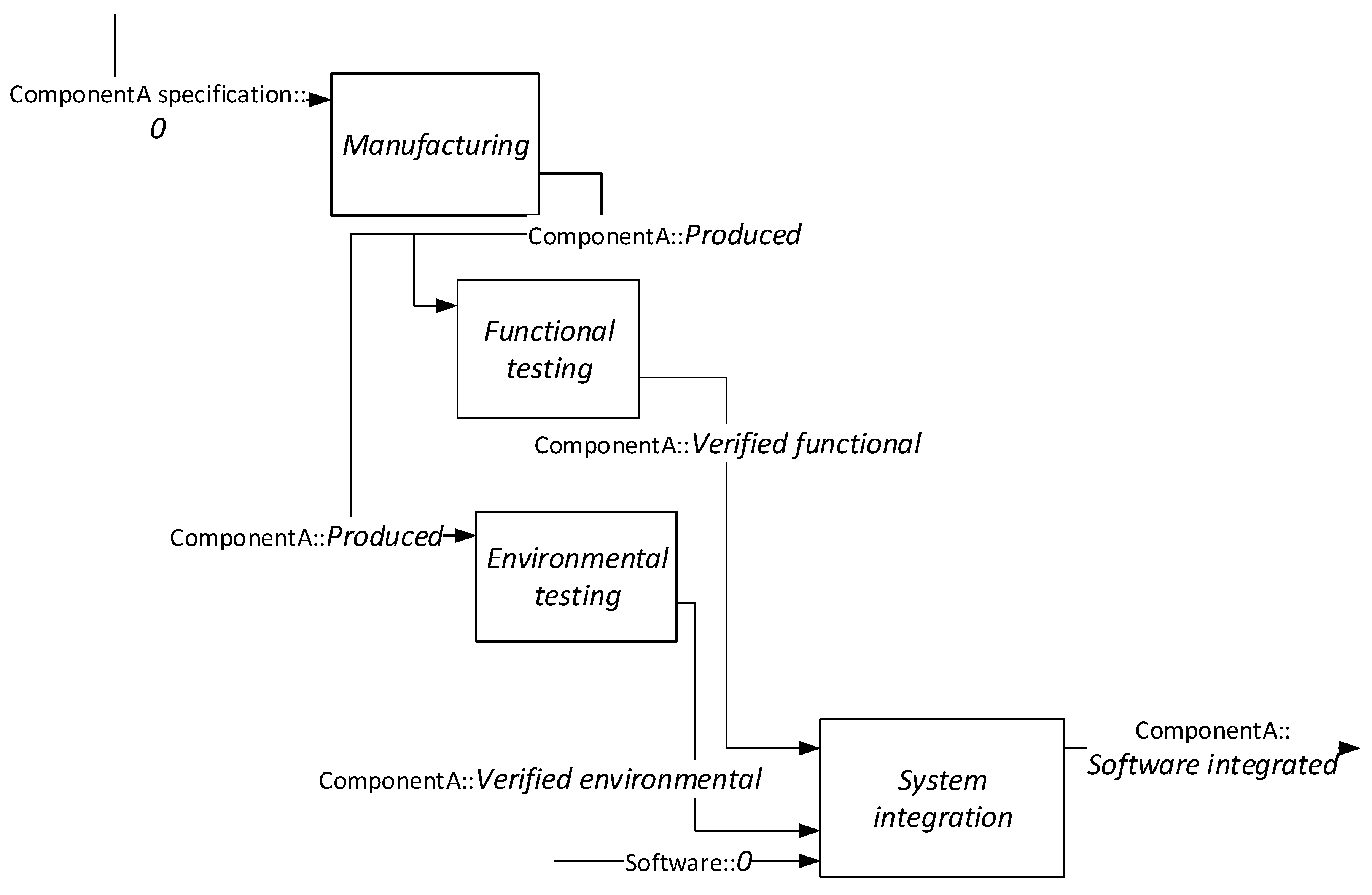
Our demonstration relies on extensive experience with modeling in both academia and industry. Our research is designed as a generalized single case study, and therefore may be of limited context. The additional reflection on the previously published process description model—by comparing the GPM representation (Figure 14) and the DSM representation (Figure 13)—further attests to the representativeness of our generalization. Still, additional research can be performed to establish a wider scope of validity, as well as extend our approach to other domains of modeling. Specifically, we propose further work to examine the two suggested metrics for modeling usability as those emerged in multiple observations of modeling in practice: (1) the number of model elements in a given representation as a quantitative indicator of the complexity of the modeling process as well as of the communicative conciseness; and (2) the number of available modeling tactics, as a quantitative indicator that relieves cognitive modeling complexity and promotes the creation of comparable and well-structured models if kept to a minimum (1 in our case study). These metrics—when analyzed in proper context, varied domains, and full-scale models—may serve as quantitative indications of models’ ontological clarity.

Author Contributions

Conceptualization, A.S.; methodology, A.S. and Y.R.; writing—original draft preparation, A.S.; writing—review and editing, Y.R.; visualization, A.S.; supervision, Y.R. All authors have read and agreed to the published version of the manuscript.

Funding

This research received no external funding.

Informed Consent Statement

Not applicable.

Data Availability Statement

The data presented in this study are available in the article.

Conflicts of Interest

The authors declare no conflict of interest.

References

  1. Ramos, A.L.; Ferreira, J.V.; Barceló, J. Model-based systems engineering: An emerging approach for modern systems. IEEE Trans. Syst. Man Cybern. Part C 2011, 42, 101–111. [Google Scholar] [CrossRef]
  2. Estefan, J.A. Survey of model-based systems engineering (MBSE) methodologies. INCOSE MBSE Focus Group 2007, 25, 1–12. [Google Scholar]
  3. Madni, A.M.; Sievers, M. Model-based systems engineering: Motivation, current status, and research opportunities. Syst. Eng. 2018, 21, 172–190. [Google Scholar] [CrossRef]
  4. Wymore, A.W. Model-Based Systems Engineering; CRC Press: Boca Raton, FL, USA, 2018; Volume 3. [Google Scholar]
  5. Huldt, T.; Stenius, I. State-of-practice survey of model-based systems engineering. Syst. Eng. 2019, 22, 134–145. [Google Scholar] [CrossRef]
  6. McDermott, T.A.; Hutchison, N.; Clifford, M.; Van Aken, E.; Salado, A.; Henderson, K. Benchmarking the Benefits and Current Maturity of Model-Based Systems Engineering across the Enterprise; Technical Report SERC-2020-SR-001; Stevens Institute of Technology, Systems Engineering Research Center: Hoboken, NJ, USA, 2020. [Google Scholar]
  7. Gregory, J.; Berthoud, L.; Tryfonas, T.; Rossignol, A.; Faure, L. The long and winding road: MBSE adoption for functional avionics of spacecraft. J. Syst. Softw. 2020, 160, 110453. [Google Scholar] [CrossRef]
  8. Cameron, B.; Adsit, D.M. Model-based systems engineering uptake in engineering practice. IEEE Trans. Eng. Manag. 2018, 67, 152–162. [Google Scholar] [CrossRef]
  9. Chami, M.; Aleksandraviciene, A.; Morkevicius, A.; Bruel, J.M. Towards solving MBSE adoption challenges: The D3 MBSE adoption toolbox. INCOSE Int. Symp. 2018, 28, 1463–1477. [Google Scholar] [CrossRef] [Green Version]
  10. Finkelstein, A.C.; Gabbay, D.; Hunter, A.; Kramer, J.; Nuseibeh, B. Inconsistency handling in multiperspective specifications. IEEE Trans. Softw. Eng. 1994, 20, 569–578. [Google Scholar] [CrossRef] [Green Version]
  11. Herzig, S.J.; Qamar, A.; Paredis, C.J. An approach to identifying inconsistencies in model-based systems engineering. Procedia Comput. Sci. 2014, 28, 354–362. [Google Scholar] [CrossRef] [Green Version]
  12. Zacharewicz, G.; Diallo, S.; Ducq, Y.; Agostinho, C.; Jardim-Goncalves, R.; Bazoun, H.; Wang, Z.; Doumeingts, G. Model-based approaches for interoperability of next generation enterprise information systems: State of the art and future challenges. Inf. Syst. e-Bus. Manag. 2017, 15, 229–256. [Google Scholar] [CrossRef] [Green Version]
  13. Sobol, G.; Dori, D. Improving OPM Conceptual Models by Incorporating Design Structure Matrix. In Proceedings of the IEEE International Symposium on Systems Engineering (ISSE), Vienna, Austria, 12 October–12 November 2020; pp. 1–8. [Google Scholar]
  14. Finance, G. SysML Modelling Language Explained. 2010. Available online: http://www.omgsysml.org/SysML_Modelling_Language_explained-finance.pdf (accessed on 24 December 2020).
  15. Mohagheghi, P.; Dehlen, V.; Neple, T. Definitions and approaches to model quality in model-based software development–A review of literature. Inf. Softw. Technol. 2009, 51, 1646–1669. [Google Scholar] [CrossRef] [Green Version]
  16. Madni, A.M. Expanding stakeholder participation in upfront system engineering through storytelling in virtual worlds. Syst. Eng. 2015, 18, 16–27. [Google Scholar] [CrossRef]
  17. Dori, D. Model-Based Systems Engineering with OPM and SysML; Springer: New York, NY, USA, 2016. [Google Scholar]
  18. Balaban, M.; Maraee, A.; Sturm, A.; Jelnov, P. A pattern-based approach for improving model quality. Softw. Syst. Model. 2015, 14, 1527–1555. [Google Scholar] [CrossRef]
  19. Hause, M. “Are we there yet?” Assessing Quality in Model Based Systems Engineering. In Proceedings of the INCOSE International Symposium, Denver, CO, USA, 23 June 2011; Volume 21, pp. 510–522. [Google Scholar]
  20. De Oca, I.M.; Snoeck, M.; Reijers, H.A.; Rodríguez-Morffi, A. A systematic literature review of studies on business process modeling quality. Inf. Softw. Technol. 2015, 58, 187–205. [Google Scholar] [CrossRef] [Green Version]
  21. Dikici, A.; Turetken, O.; Demirors, O. Factors influencing the understandability of process models: A systematic literature review. Inf. Softw. Technol. 2018, 93, 112–129. [Google Scholar] [CrossRef] [Green Version]
  22. Dori, D.; Linchevski, C.; Manor, R. OPCAT–An Object-Process CASE Tool for OPM-Based Conceptual Modelling. In Proceedings of the 1st International Conference on Modelling and Management of Engineering Processes, Cambridge, UK, 19–20 July 2010; University of Cambridge: Cambridge, UK, 2010; pp. 1–30. [Google Scholar]
  23. ISO. ISO/PAS 19450:2015—Automation Systems and Integration—Object-Process Methodology; International Organization for Standardization: Geneva, Switzerland, 2015. [Google Scholar]
  24. Shaked, A.; Reich, Y. Designing development processes related to system of systems using a modeling framework. Syst. Eng. 2019, 22, 561–575. [Google Scholar] [CrossRef]
  25. Shaked, A.; Reich, Y. Improving Process Descriptions in Research by Model-Based Analysis. IEEE Syst. J. 2020. [Google Scholar] [CrossRef]
  26. Bernal, M.; Haymaker, J.R.; Eastman, C. On the role of computational support for designers in action. Des. Stud. 2015, 41, 163–182. [Google Scholar] [CrossRef]
  27. Achinstein, P. Theoretical models. Br. J. Philos. Sci. 1965, 16, 102–120. [Google Scholar] [CrossRef]
  28. Wand, Y.; Weber, R. On the ontological expressiveness of information systems analysis and design grammars. Inf. Syst. J. 1993, 3, 217–237. [Google Scholar] [CrossRef]
  29. Kim, S.; Wagner, D.; Jimemez, A. Challenges in Applying Model-Based Systems Engineering: Human-Centered Design Perspective. In Proceedings of the INCOSE Human-Systems Integration Conference, Biarritz, France, 11–13 September 2019; Available online: https://opencaesar.github.io/papers/2019-09-11-MBSE-Challenges.html (accessed on 31 January 2020).
  30. Yang, L.; Cormican, K.; Yu, M. Ontology-based systems engineering: A state-of-the-art review. Comput. Ind. 2019, 111, 148–171. [Google Scholar] [CrossRef]
  31. Wand, Y.; Weber, R. Research commentary: Information systems and conceptual modeling—A research agenda. Inf. Syst. Res. 2002, 13, 363–376. [Google Scholar] [CrossRef] [Green Version]
  32. Jørgensen, H.D. Interactive Process Models; Norwegian University of Science and Technology: Trondheim, Norway, 2004. [Google Scholar]
  33. Bork, D.; Karagiannis, D.; Pittl, B. A survey of modeling language specification techniques. Inf. Syst. 2020, 87, 101425. [Google Scholar] [CrossRef]
  34. Unger, D.; Eppinger, S. Improving product development process design: A method for managing information flows, risks, and iterations. J. Eng. Des. 2011, 22, 689–699. [Google Scholar] [CrossRef]
  35. Gericke, K.; Qureshi, A.J.; Blessing, L. Analyzing transdisciplinary design processes in industry: An overview. In Proceedings of the International Design Engineering Technical Conferences and Computers and Information in Engineering Conference, Portland, OR, USA, 4–7 August 2013; American Society of Mechanical Engineers: New York, NY, USA, 2013; Volume 55928. [Google Scholar]
  36. Wynn, D.C.; Clarkson, P.J. Process models in design and development. Res. Eng. Des. 2018, 29, 161–202. [Google Scholar] [CrossRef] [Green Version]
  37. Object Management Group. OMG Systems Modeling Language Version 1.6; Object Management Group: Milford, MA, USA, 2019. [Google Scholar]
  38. Object Management Group. BPMN 2.0—Formal Specification; Object Management Group: Milford, MA, USA, 2011. [Google Scholar]
  39. Sharon, A.; Dori, D. Model-Based Project-Product Lifecycle Management and Gantt Chart Models: A Comparative Study. Syst. Eng. 2017, 20, 447–466. [Google Scholar] [CrossRef]
  40. Frank, U. Domain-specific modeling languages: Requirements analysis and design guidelines. In Domain Engineering; Springer: Berlin/Heidelberg, Germany, 2013; pp. 133–157. [Google Scholar]
  41. Sharon, A.; De Weck, O.; Dori, D. Improving project–product lifecycle management with model–based design structure matrix: A joint project management and systems engineering approach. Syst. Eng. 2013, 16, 413–426. [Google Scholar] [CrossRef]
  42. Li, L.; Soskin, N.L.; Jbara, A.; Karpel, M.; Dori, D. Model-based systems engineering for aircraft design with dynamic landing constraints using object-process methodology. IEEE Access 2019, 7, 61494–61511. [Google Scholar] [CrossRef]
  43. Soffer, P.; Golany, B.; Dori, D.; Wand, Y. Modelling off-the-shelf information systems requirements: An ontological approach. Requir. Eng. 2001, 6, 183–199. [Google Scholar] [CrossRef]
  44. Vandekerckhove, J.; Matzke, D.; Wagenmakers, E.J. Model comparison and the principle of parsimony. In Oxford Handbook of Computational and Mathematical Psychology; Oxford University Press: Oxford, UK, 2015; pp. 300–319. [Google Scholar]
  45. Capella 1.4.0 Release Notes. Available online: https://github.com/eclipse/capella/wiki/Release-Notes-1.4.0 (accessed on 18 December 2020).
  46. Pullonen, P.; Tom, J.; Matulevičius, R.; Toots, A. Privacy-enhanced BPMN: Enabling data privacy analysis in business processes models. Softw. Syst. Model. 2019, 18, 3235–3264. [Google Scholar] [CrossRef]
  47. Bazoun, H.; Zacharewicz, G.; Ducq, Y.; Boye, H. Transformation of extended actigram star to BPMN2.0 and simulation model in the frame of model driven service engineering architecture. In Proceedings of the Symposium on Theory of Modeling & Simulation-DEVS Integrative M&S Symposium, San Diego, CA, USA, 7–10 April 2013; Society for Computer Simulation International: San Diego, CA, USA, 2013; pp. 1–8. [Google Scholar]
Figure 1. OPM diagram in OPCAT modeling tool, after adding object, process, and state elements.
Applsci 11 01532 g001
Figure 2. Linking objects and process, option #1.
Applsci 11 01532 g002
Figure 3. Linking objects and process, option #2.
Applsci 11 01532 g003
Figure 4. Linking objects and process, option #3.
Applsci 11 01532 g004
Figure 5. Linking objects and process, option #4.
Applsci 11 01532 g005
Figure 6. Linking objects and process, option #5.
Applsci 11 01532 g006
Figure 7. Linking objects and process, option #6.
Applsci 11 01532 g007
Figure 8. Linking objects and process, option #7.
Applsci 11 01532 g008
Figure 9. Complete process description OPM model, after making use of Process Oriented Viewpoint for Engineering (PROVE) methodology.
Applsci 11 01532 g009
Figure 10. PROVE composite-state construct represented using OPM.
Applsci 11 01532 g010
Figure 11. Process description modeled in OPM using PROVE’s Development Process Design (DPD) ontology.
Applsci 11 01532 g011
Figure 12. Process description modeled PROVE.
Applsci 11 01532 g012
Figure 13. PROVE diagram of the Intellectual Property (IP) Protection Oversight case study (adopted from [24]).
Applsci 11 01532 g013
Figure 14. OPM diagram of the IP Protection Oversight case study.
Applsci 11 01532 g014
Table 1. Process description to be modeled.
Process Description to Be Modeled (Extract)
1. A manufacturing activity produces the component ComponentA, according to a component specification.
2. Functional testing activity verifies ComponentA with respect to its functional requirements.
3. Environmental testing activity approves the component with respect to its environmental operating conditions.
4. A system integration activity integrates the physical component—after it was verified with respect to its functional and environmental aspects—with a designated software version.
Table 2. Process description analyzed for Object Process Methodology (OPM) modeling.
Process Description Section #ProcessInput/OutputObjectObject State
1ManufacturingInputComponentA specification? (Unspecified)
OutputComponentAProduced
2Functional testingInputComponentAProduced
OutputComponentAVerified functional [our state designation for “verified with respect to functional requirements]
3Environmental testingInputComponentAProduced
OutputComponentAVerified environmental [our state designation for “verified with respect to environmental operating conditions”]
4System integrationInputComponentAVerified environmental, Verified functional
InputSoftware? (Unspecified)
OutputComponentASoftware integrated
Table 3. Summary of results.
Number of Elements in OPM Model (Rigorous Model Based on PROVE)Number of Elements in PROVE ModelRatio of Number of Elements between OPM and PROVE
Case 141113.73
Case 274282.64
Publisher’s Note: MDPI stays neutral with regard to jurisdictional claims in published maps and institutional affiliations.

