Design and Accuracy Analysis of a Micromachine Tool with a Co-Planar Driving Mechanism


Abstract
1. Introduction
2. Principle of the Co-Plane Platform
2.1. Principle
2.2. Kinematic Analysis
- (a)
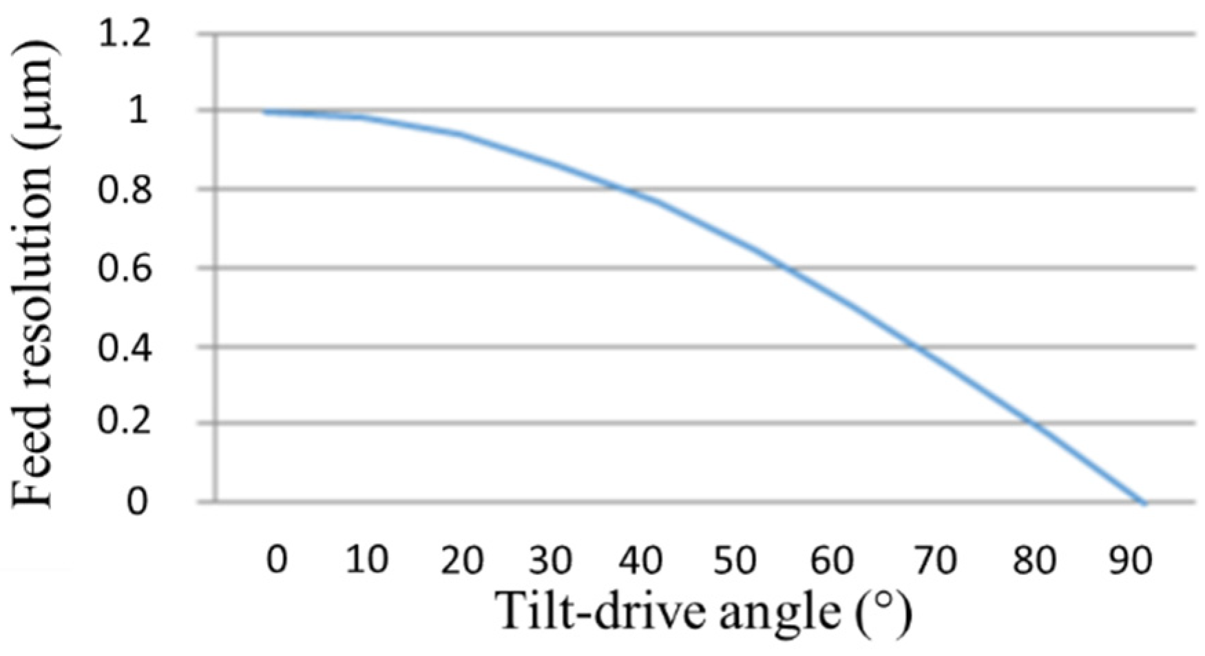
- Relationship between feed resolution of platform and tilt-drive angleWhile the platform carries out the axial feed, the resolution is decided by the tilt-drive angle. The feed resolution can be calculated as followswhere RP is the feed resolution of the platform, RB is the movement resolution of the ballscrew, and θ is the angle between the sliding rod and the ballscrew
- (b)
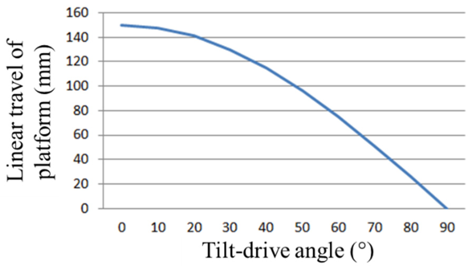
- Relationship between the X and Z movement of platform and the tilt-drive angleThe co-planar axial linear movement of the platform depends on the length of the ballscrew and the tilt angle. The relationship can be expressed as followswhere DP is the platform movement, DB is the ballscrew movement, and θ is the angle between the sliding rod and the ballscrew
- (c)
- The relationship between the rotation resolution of the platform and the range of the rotation angleTo understand the relationship between the rotation resolution of the platform and the rotation angle, it is necessary to first derive the relationship between the travel distance of the ballscrew nut and the rotational angle of the platform. When the platform is rotated, the travel distance of the tilt-drive servo sliding block (shown in Figure 3) can be calculated as followswhere l1 is the travel distance of the servo-drive sliding block when the platform rotates about the B-axis, f is the distance from the connection point to the center of the platform, θ’ is the angle before rotation, and θ” is the angle after rotation.
3. Error Model and Analysis
3.1. Error Model
3.2. Error Sensitivity Analysis
3.3. Ballscrew Motion Error and Feed Error Analysis
3.4. Tilt-Drive Angular Position Error and Feed Error Analysis
4. Accuracy and Machinability Test
5. Conclusions
Author Contributions
Funding
Institutional Review Board Statement
Informed Consent Statement
Data Availability Statement
Acknowledgments
Conflicts of Interest
References
- Dornfeld, D.; Mina, S.; Takeuchi, Y. Recent advances in mechanical micromachining. CIRP Ann. 2006, 55, 745–768. [Google Scholar] [CrossRef]
- O’Hara, J.; Fang, F. Advances in micro cutting tool design and fabrication. Int. J. Extrem. Manuf. 2019, 1, 032003. [Google Scholar] [CrossRef]
- Camara, M.A.; Campos Rubio, J.C.; Abrao, A.M.; Davim, J.P. State of the art on micromilling of materials, a review. J. Mater. Sci. Technol. 2012, 28, 673–685. [Google Scholar] [CrossRef]
- Liu, X.; DeVor, R.E.; Kapoor, S.G.; Ehmann, K.F. The mechanics of machining at the microscale: Assessment of the current state of the science. J. Manuf. Sci. Eng. 2004, 126, 666–678. [Google Scholar] [CrossRef]
- Zhao, J.; Jiang, Z.; Dobrzanski, L.A.; Lee, C.S.; Yu, F. Recent development in micromanufacturing of metallic materials. Materials 2020, 13, 4046. [Google Scholar] [CrossRef] [PubMed]
- Park, M.H.; Kim, K.S. Chattering reduction in the position control of induction motor using the sliding mode. IEEE Trans. Power Electron. 1991, 6, 317–325. [Google Scholar] [CrossRef]
- Takeuchi, Y.; Yonekura, H.; Sawada, K. Creation of 3-D tiny statue by 5-axis control ultraprecision machining. Comput. Aided Des. 2003, 35, 403–409. [Google Scholar] [CrossRef]
- Wang, D.; Sui, Y.; Yang, H.; Li, D. Adaptive spiral tool path generation for diamond turning of large aperture freeform optics. Materials 2019, 12, 810. [Google Scholar] [CrossRef] [PubMed]
- Wang, S.M.; Ye, Z.Z.; Yang, C.P.; Yen, C. A low-cost and high-resolution micromachine tool with toggle-based mechanism. J. Micro Nanomanuf. 2015, 3, 014501-1–014501-5. [Google Scholar] [CrossRef]
- Wang, S.M.; Ye, Z.Z.; Yeh, C.C.; Gunawan, H.; Chiu, H.S. New design of a low-cost micro machine tool with the high-precision variable-resolution mechanism. Opt. Quant. Electron. 2016, 48, 565. [Google Scholar] [CrossRef]
- Wojciechowski, S.; Matuszak, M.; Powalka, B.; Madajewski, M.; Maruda, R.W.; Krolczyk, G.M. Prediction of cutting forces during micro end milling considering chip thickness accumulation. Int. J. Mach. Tool. Manuf. 2019, 147, 103466. [Google Scholar] [CrossRef]
- Law, M.; Altintas, Y.; Phani, A.S. Rapid evaluation and optimization of machine tools with position-dependent stability. Int. J. Mach. Tool. Manuf. 2013, 68, 81–90. [Google Scholar] [CrossRef]


| Translation Error Sources | Rotation Angle Error Sources |
|---|---|
| , , | , , |
| , , | , , |
| , , | , , |
| , , | , , |
| , , | , , |
| , , | , , |
| , , | , , |
| , , | , , |
| , , | , , |
| , , | , , |
| , , | , , |
| , , | , , |
| , | , , |
| , , |
| Motion Errors | Description |
|---|---|
| , | X, Y direction motion error when the D ballscrew moves |
| X, Z direction motion error when the C ballscrew moves | |
| , | X, Z direction motion error when the B ballscrew moves |
Publisher’s Note: MDPI stays neutral with regard to jurisdictional claims in published maps and institutional affiliations. |
© 2021 by the authors. Licensee MDPI, Basel, Switzerland. This article is an open access article distributed under the terms and conditions of the Creative Commons Attribution (CC BY) license (http://creativecommons.org/licenses/by/4.0/).
Share and Cite
Wang, S.-M.; Ye, Z.-Z.; Gunawan, H. Design and Accuracy Analysis of a Micromachine Tool with a Co-Planar Driving Mechanism. Appl. Sci. 2021, 11, 947. https://doi.org/10.3390/app11030947
Wang S-M, Ye Z-Z, Gunawan H. Design and Accuracy Analysis of a Micromachine Tool with a Co-Planar Driving Mechanism. Applied Sciences. 2021; 11(3):947. https://doi.org/10.3390/app11030947
Chicago/Turabian StyleWang, Shih-Ming, Zhe-Zhi Ye, and Hariyanto Gunawan. 2021. "Design and Accuracy Analysis of a Micromachine Tool with a Co-Planar Driving Mechanism" Applied Sciences 11, no. 3: 947. https://doi.org/10.3390/app11030947
APA StyleWang, S.-M., Ye, Z.-Z., & Gunawan, H. (2021). Design and Accuracy Analysis of a Micromachine Tool with a Co-Planar Driving Mechanism. Applied Sciences, 11(3), 947. https://doi.org/10.3390/app11030947