Article

Performance Study of Grass-Derived Nano-Cellulose and Polycaprolactone Composites for 3D Printing

1
College of Animal Science and Technology, Yangzhou University, Yangzhou 225009, China
2
Yangzhou Polytechnic Institute, Yangzhou 225127, China
3
College of Mechanical Engineering, Yangzhou University, Yangzhou 225127, China
4
College of Medical, Yangzhou University, Yangzhou 225009, China
*
Author to whom correspondence should be addressed.
Appl. Sci. 2021, 11(3), 1273; https://doi.org/10.3390/app11031273
Submission received: 17 December 2020 / Revised: 26 January 2021 / Accepted: 26 January 2021 / Published: 30 January 2021
(This article belongs to the Special Issue Application of Biomaterials for Tissue Engineering)

Abstract

:
In recent years, 3D printing has received increasing attention from researchers. This technology overcomes the limitations of traditional technologies by printing precise and personalized scaffold with arbitrary shapes, pore structures, and porosities for the applications in various tissues. The cellulose nanocrystal (CNC) is extracted from Humulus Japonicus (HJS) and mixed with poly(ε-caprolactone) (PCL) to prepare a series of CNC/PCL composites for printing. Based on the analysis of the physical and chemical properties of the series of the CNC/PCL composites, an optimal mass ratio of CNC to PCL was obtained. The Solidworks was used to simulate the stretching and compression process of the scaffolds with three different patterns under an external force. The flow of nutrient solution in the scaffolds with different patterns was simulated by ANSYS FLUENT, and then a new optimization scaffold pattern with a concave hexagon shape was advised based on the simulation results. Collectively, the mechanical test results of the material and scaffold confirmed that the optimal filling amount of the CNC was 5%, and the scaffold pattern with concave hexagon shape exhibited better mechanical properties and suitable for the transport of cells and nutrients, which is expected to be more widely used in 3D printing.

1. Introduction

The demand for tissue and organ replacement, repair, and regeneration is growing due to increasing traumatic injury or disease cases, limited sources of donor organs, and immune rejection of donor tissues, which are such that demand exceeds supply [1]. Therefore, this has promoted researches in tissue engineering and regenerative medicine, especially the emerging hotspot of biological scaffolds [2,3,4]. Nowadays, an emerging 3D printing technology can compensate for the shortcomings of traditional manufacturing methods. It is an additive manufacturing method that uses biomaterials to print precise, bionic, and personalized scaffold structures in a layer-by-layer manner, with the ability to modify the shape, size, structure, and porosity of the scaffold [5,6]. In order to obtain suitable scaffolds, various methods including selective laser sintering (SLS) [7], fused deposition modeling (FDM) [8,9], laminated object manufacturing (LOM) [10,11], stereolithography apparatus (SLA) [12,13], and others were developed. Among these, FDM is one of the most common and easily-implemented 3D printing processes [14].
PCL is a biodegradable biomaterial with good biocompatibility, mechanical strength and durability, good thermo-plasticity, easy processing, and low melting point, which makes PCL widely used in tissue engineering [15,16,17]. There are two main challenges for PCL as a tissue engineering material. One is hydrophobicity, as studies have shown that cells are more likely to adsorb, grow and migrate on hydrophilic scaffolds [18], which can be solved by blending PCL with hydrophilic polymers [19,20]. Secondly, mechanical strength limits its application in tissue engineering such as skin, blood vessels, tendons, and bones, which require sufficient mechanical strength, and one effective way is to add nanofillers [21]. Cellulose nanocrystal, as a new functional polymeric material [22,23], has been extensively studied to show that composites with CNC as the reinforcing phase not only improve the material properties but also achieve controllable properties of composites, compared to single-component materials [24]. CNC isolated from plant cellulose have attracted considerable attention due to their high aspect ratio, high strength, abundant hydroxyl groups, low cost, widely available, and good biocompatibility. At present, there are two main sources of nanocellulose, one is from plants, the other is from bacterial metabolites. Moreover, it’s more economical and convenient to get it from plants.
The design of the scaffold must have a porous structure and suitable porosity to obtain the desired mechanical function and mass flow [25]. The results indicate [26,27,28] that cell viability and proliferation can be enhanced by varying the microporous geometry and porosity of the scaffold. High porosity and pore size benefit in nutrient and oxygen delivery or allow more cells to grow inward, but the mechanical properties of the scaffold will be compromised due to the large pore volume. Therefore, the microporous structure and porosity of the scaffold should be considered during scaffold design and fabrication to achieve a good balance between mechanical properties and mass transfer [28,29].
To address the above issues, the introduction of CNC into PCL nanofibers is utilized to prepare CNC/PCL composites, and the influence of the physicochemical properties and cytocompatibility of CNC/PCL composites is explored in order to obtain composites with good mechanical properties, as well as the cytocompatibility for their applications in tissue engineering. The properties of different pore shapes were tested by varying the pore shape of the printed scaffold. In addition, three different orthogonal, triangular, and concave hexagon pore shapes were compared, in combination with software simulation to analyze the mechanical properties of the different pore shapes and the flow of liquid in the scaffold. For 3D printed biological scaffold, mechanical properties are one of the important criteria of the scaffold, so the development of a suitable testing biological scaffold tensile and compression tester is also one of the key factors, which can provide application technical support for the mechanical properties testing on the scaffold.
At present, there are not many literatures about 3D printing CNC/PCL, only a small number of PCL/CNC mixtures. This research will provide an important theoretical basis for the utilization of grass material, the change of filling pattern of printing scaffold, and the application of 3D printing new biomaterials in tissue engineering.

2. Materials and Methods

2.1. Materials

Polycaprolactone (PCL, relative molecular mass 8000, BR) was purchased from Shenzhen Guanghua Weiye Co., Ltd. (Shenzhen, China) Dichloromethane (DCM, AR) and Sulphuric acid (AR) were obtained from Tianjin Comeo Co., Ltd. (Tianjin, China).

2.1.1. Preparation of CNC/PCL Composite Materials

The CNC was isolated from Humulus Japonicus stem using sulphuric acid hydrolysis method which has been reported in our previous study [30]. Briefly, the HJS powder was treated with 4% sodium hydroxide solution at 80 °C for 2 h and treated 3 times with 5% acidified sodium chlorite at 80 °C for 6 h (2 h each time) to remove hemi-cellulose and lignin. Next, the bleached HJS powder was hydrolyzed using 60% sulfuric acid at 45 °C for 1 h with strong agitation using an electric mixer (OS-Pro, Kexing, Shanghai, China) at 2000 rpm. The reaction was terminated by the addition of a volume of water 10 times that of the reaction solution. The suspension was filtered using a filter paper (GF/B1442-150, Whatman, England, UK) with a pore size of 2.5μm and subsequently centrifuged using a centrifuge (80-2B, JTLIANGYOU, Changzhou, China) at 10 °C and 10,000 rpm and dialyzed using a pH Sensor (51343050, Mettler Toledo, Shanghai, China) until its pH value was to 7. This process is known to produce finely divided CNC (See the supplementary material Figure S1 for the TEM images of CNC). Then the CNC after freeze-drying spray drying treatment using a vacuum dryer (DZF-6020, Jingfu, Shanghai China) were added to the dichloromethane solution and dispersed using an ultrasonic (WZB-DC, Weizhibo, Beijing, China) for 48 h to ensure the formation of a homogeneous solution. The CNC extracted by sulfuric acid hydrolysis method was used as biocompatible material. We dialyzed it repeatedly until its pH value reached 7 to ensure the removal of residual sulfuric acid. In addition, the materials were disinfected before cell culture, soaked in alcohol for 24 h, and treated with ultraviolet light for 24 h. The whole printing process is aseptic. Four equal sets of PCL particles were dissolved in the mixed solution and stirred until a homogeneous solution was formed. As shown in Table 1, The filling amount of the CNC was 0%, 1%, 3%, and 5% of the PCL particle mass. The samples were dried by vacuum dryer and were labeled as CNC-X/PCL, and X was the filling amount of the CNC.
For the filled pattern, a new filled pattern is designed with the idea that each layer of the scaffold is divided into several concave hexagons that are separated from each other. As shown in Figure 1a, three sides of each concave hexagon are stacked on the filaments below to improve the vertical compression resistance of the bracket. The other three sides are suspended and attached to the filaments below to form a simply supported beam structure to increase the porosity of the bracket. This is shown in Figure 1b.
In order to evaluate the porosity and mechanical properties of the scaffolds printed through different filled patterns, a 3D model (20 mm × 20 mm × 1 mm) was created using Solidworks 2018 software. For this material, we designed a study using the common orthogonal, triangular, and designed concave hexagon filled patterns. The models of the three different filled patterns are shown in Figure 2.
Solving the above theoretical model, the scaffold material is PCL/CNC, and to calculate the porosity of the scaffold printed using different filling methods, several physical parameters were evaluated by Solidworks. The theoretical volume (V) was calculated by measuring the length (L), width (W), and height (H) of the scaffold. After entering the theoretical density (ρ), the actual weight (m) was evaluated by Solidworks. Porosity is an important metric for evaluating scaffold performance, and the porosity of the scaffold model, or porosity, can be expressed as
P = 1 − m/ρV
In terms of the scaffold graphical pattern, it is required to have sufficiently high porosity and sufficiently high mechanical properties. Meanwhile, the porosity and mechanical properties of the scaffold are a contradiction, as a high porosity will inevitably lead to a decrease in the mechanical properties of the scaffold. Therefore, the relationship between porosity and mechanics of different scaffolds can be calculated by the simulation to compare the mechanical properties of different filled pattern.

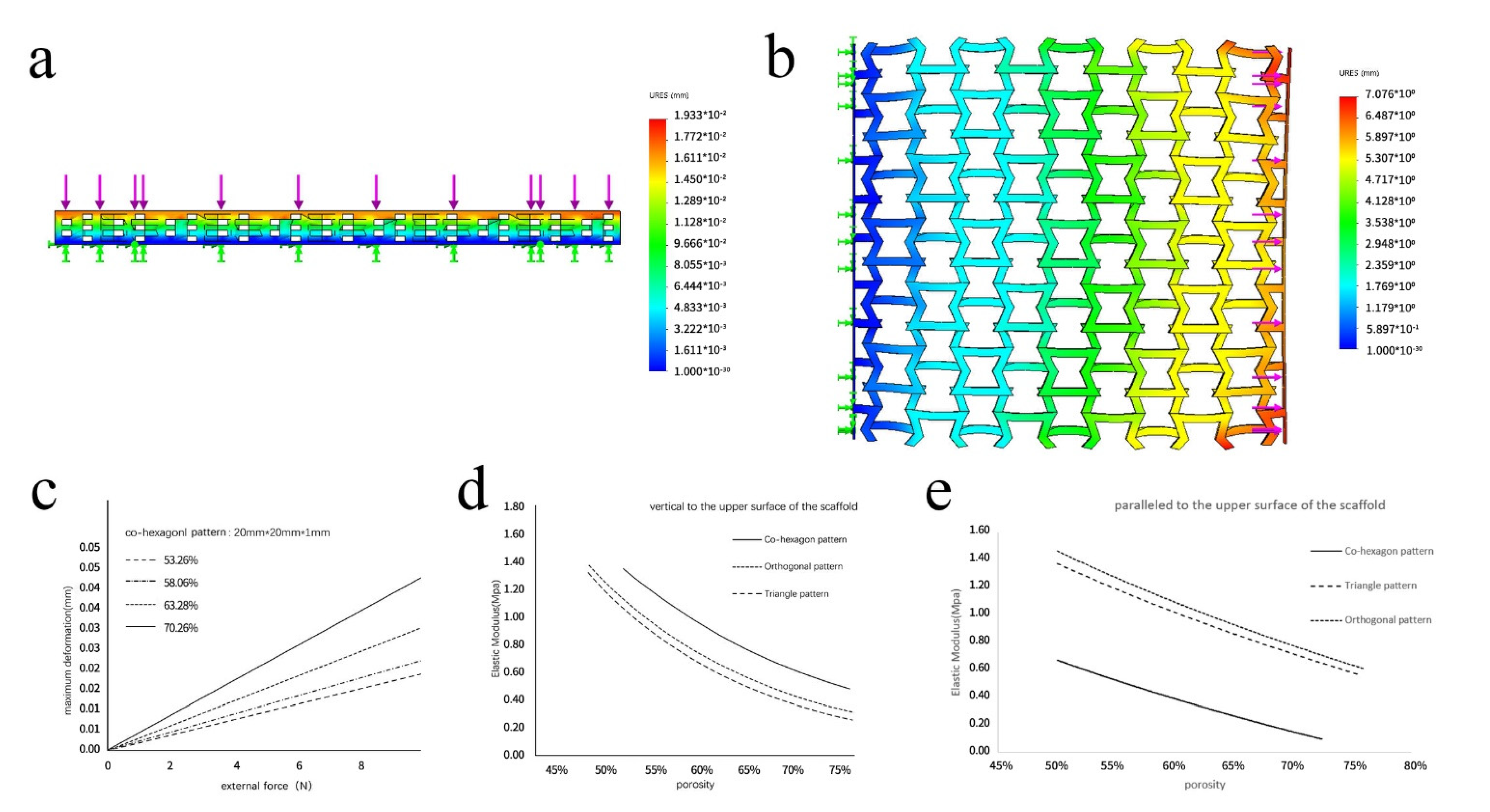
2.1.2. Mechanical Simulation with Solid Works Simulink

In order to assess the mechanical properties, three scaffolds with different filling patterns have been built using Solidworks 2018. The material of the scaffold has been customized according to CNC/PCL, the modulus of elasticity of the material has been determined to be 4 MPa, and the density has been determined to be 1146 kg/m3 by measuring the volume and weight of the standard specimens. Then tensile and compressive simulations in different directions have been performed by Simulink, a modular of Solidworks. As shown in Figure 3 is the side view of the simulation model (a), the vertical direction is stressed on the upper surface of the bracket (b) and the stretching is parallel to the upper surface of the bracket (c). For the tensile and compression simulations in the vertical direction, the steel cover below the scaffold is fixed and tensile/compressive loads are applied to the steel cover above the scaffold (see Figure 3). The scaffold is cut into individual small pieces by MESH function before simulation, and the maximum stress and maximum strain are recorded as simulation results. Similarly, tensile compression tests in other directions were performed by changing the load.
In order to test the influence of different filling patterns on the mechanical properties (including tensile properties and compressive properties) of scaffolds, the deformation and stress of different filling patterns, orthogonal, triangular, and concave hexagonal, were tested under pressure vertical to the upper surface of the scaffold or tension parallel to the upper surface of the scaffold. In order to eliminate simulation errors due to boundary effects, each model was tested 10 times. In the first test, the pressure/tension was 1 N. In each subsequent test, the pressure/tension was increased by 1 N until it reached 10 N in the last test. The average elastic modulus value was obtained and recorded.

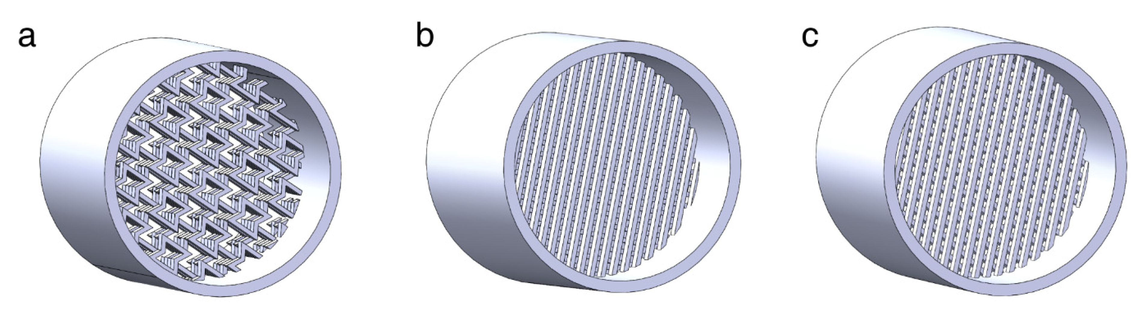
2.1.3. Printing of the Scaffold

According to the material preparation scheme of 2.1.2, four composites were prepared, PCL, CNC-1/PCL, CNC-3/PCL, and CNC-5/PCL, respectively, and according to the printability analysis of the composites with different mixing ratios under the same printing parameters (See Figure S2), the optimal proportion of materials were selected to be loaded into the barrel of the biological 3D printer (MEP221, Bobang, Tianjin, China) to be used. The 3D bio-printer is equipped with a high-temperature nozzle. The maximum temperature of the nozzle can reach 260 °C. A rectangular model 20 mm × 20 mm × 1 mm was created to generate the print path. After many experiments, we chose a set of optimum parameters, the optimum temperature for extruding the material to obtain continuous silks is between 95 °C and 100 °C. The effect of the silks is the same, so we defined the temperature of the nozzle was 97 °C, the diameter of the print needle was 0.2 mm, and the movement speed was 5 mm/sin the printing process.

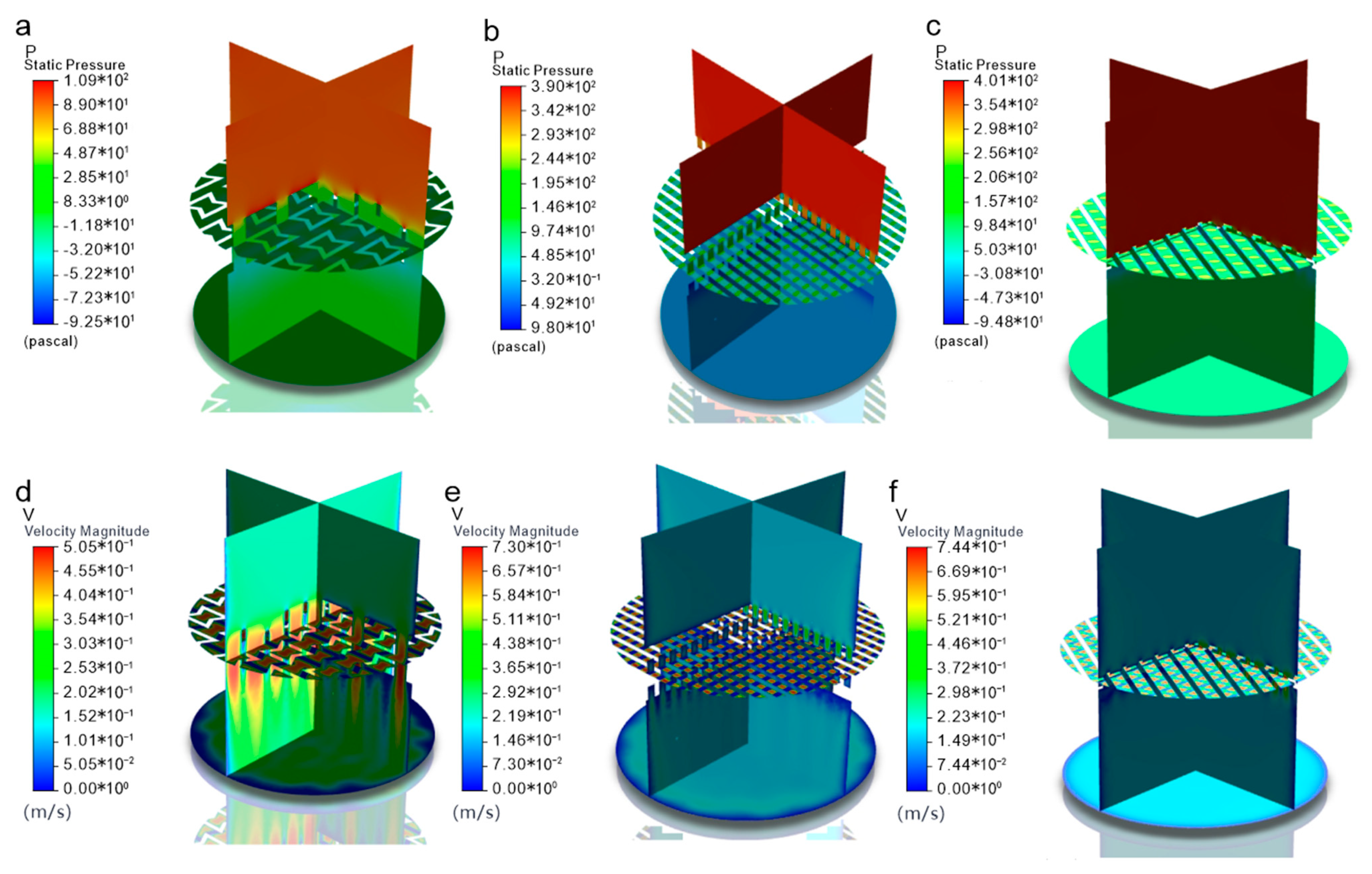
2.1.4. Numerical Simulation of the Flow Field in the Scaffolds

Cells need to be artificially cultured on the prepared porous scaffolds, and the success of cell culture depends on the supply of nutrient solution in the scaffolds, so the development of the scaffold model and the flow conditions of nutrient solution and cells in the porous scaffolds is an important issue to be investigated. If the fluid velocity is well-distributed in the scaffold, it is suitable for the delivery of cell and nutrient solution, and the cells are also easy to deposit on the scaffold. Based on the above three different filling shapes of the scaffolds, the scaffold model was developed and the flow conditions of cells and nutrient solution in the scaffolds were simulated using ANSYS FLUENT software. As shown in Figure 4, the schematic diagram of the computational model of the concave hexagon, orthogonal pattern, and triangular scaffold, respectively, both nutrient solution and cells need to flow and grow on the scaffold. According to the geometrical structural parameters of the scaffold, the density of the mesenchymal stem cell culture medium used in the simulation is 1100 kg/m3 with a viscosity of 0.0018 Pa.s, the density of cells is 1200 kg/m3, the volume fraction occupied by cells is 0.02, the proportion in the mixture is small, and the average flow rate of the nutrient solution is 0.19 m/s [31].

2.2. Characterizations

2.2.1. Scanning Electron Microscopy (SEM)

The microstructure of solid samples was evaluated using a scanning electron microscope with an accelerating voltage of 5 kV (S-4800, Hitachi, Tokyo, Japan). All samples were frozen in liquid nitrogen and destroyed with two clamps to expose the cross-sections before SEM observation. SEM observations were performed after sputtering the samples with a thin film of gold for 40 s.

2.2.2. Assessment of Rheological Property

Rheological measurements were performed on a stress-controlled DHR-2 rheometer from TA Instruments. The samples were measured by using a 25 mm plate-plate geometry and frequency sweeps were performed at 90 °C in an angular frequency range of 0.01–1000 rad/s.

2.2.3. Assessment of Mechanical Properties

The mechanical properties of the material samples were checked in a single cantilever mode by the DMA Q800. The sample was trimmed to 4 mm length, 2 mm width, and 2 mm thickness. Measure the force properties of the material by increasing the velocity from 1 N to 18 N at 1 N/min.
The mechanical properties of the printed scaffolds were measured using a special instrument that was designed and prepared by our team. In the existing measurement and analysis experiments, the common tensile tester cannot meet the test of biological materials, cannot measure their small deformation, and can only single measure the tensile or compression of the material, for this experiment, an automatic tensile stiffness tester (See Figures S3 and S4.) is designed to measure the mechanical properties of the scaffold in different directions [32,33].

2.2.4. Biocompatibility Assessment

To prove its biocompatibility, 0.5 g of three groups of materials (PCL group, CNC-3/PCL group, control group) were taken by 15 mL centrifugal tubes, respectively soaked in PBS solution containing double antibodies for 1 h and irradiated under UV light for 1 h. After incubation in a 70-degree water bath for 1 h, 3 mL of complete culture medium was added to each tube at 37 degrees for 24 h, followed by cell digestion, counting, and preparation. Subsequently, 100 μL of cell suspension was added to each well of a 96-well plate (2.5 × 10³ cells per well). The plate was then incubated in a 5% CO2 incubator at 37 °C overnight; 100 μL of the corresponding extract was added to each well, and a normal culture medium was added to the control group. The supernatant was discarded after 1d, 2d, 3d, 4d, and 5d incubation at 37 °C and 5% CO2 incubator, and the cells were washed twice with fresh culture medium. The cells in 96-well plates were stained with CCK-8 and the OD values at λ = 450 nm were measured; the cell growth curve was plotted with time as the horizontal coordinate and the OD450 value as the vertical coordinate.

3. Results and Discussion

3.1. Bioprinted Material Characterization Test Results

3.1.1. SEM Observation of Surface Morphology

The cross-section of the solid sample of PCL/CNC was ruptured to observe the dispersion of CNC in the PCL matrix. As shown in Figure 5, the CNC is uniformly dispersed in the PCL and exposed as small dots (approximately 100 nm in diameter). This is due to the rupture of the sample along the cross-section perpendicular to the melt flow direction during the molding process. The injection flow causes the CNCs to align along the flow direction [34]. Besides, as the CNC content increases, more bulges, such as elevations, appear in the image, indicating that CNCs in other directions are buried in the PCL matrix. In particular, in 5% of the CNC samples (Figure 6d), some bumps merge with dots, indicating that the CNCs are aggregated within the PCL matrix, As the CNC content increased, more CNC particles were observed. In addition, no significant voids were observed in the images, thus indicating a strong interfacial interaction between CNC and PCL.

3.1.2. Analysis of Rheological Property

In order to better understand the influence of the nanofiller on the shear-induced crystallization, the rheological properties of the composites were also investigated. In Figure 6a results from measurements done at 90 °C are presented. It can be seen from the figure that the viscosity of all samples decreases with the increase of shear rate, that is, they all have the characteristics of “shear thinning”. In addition, it can be observed that the viscosity of PCL is increased by the addition of CNC, indicating that CNC can form a network structure in the PCL matrix, thereby promoting the viscosity of PCL/CNC nanocrystalline composites under high temperature. In the process of 3D printing, when the non-Newtonian fluid flows in the nozzle under pressure, there is a shear force between different layers. The characteristic of “shear thinning” reduces the viscosity of the composite material under the shear force, which is convenient for it to pass through the nozzle [35].
As shown in Figure 6b,c, the storage modulus and loss modulus of PCL/CNC nanocomposites are higher than those of pure PCL, and they increase significantly with the increase of CNC content in all frequency ranges and tend to be stable gradually [36]. This is because CNC itself is a rigid material, and the modulus reaches 130 Gpa, it is 25 times that of steel, and the network structure of CNC is formed in the composite, which enhances the intermolecular force in the composite.

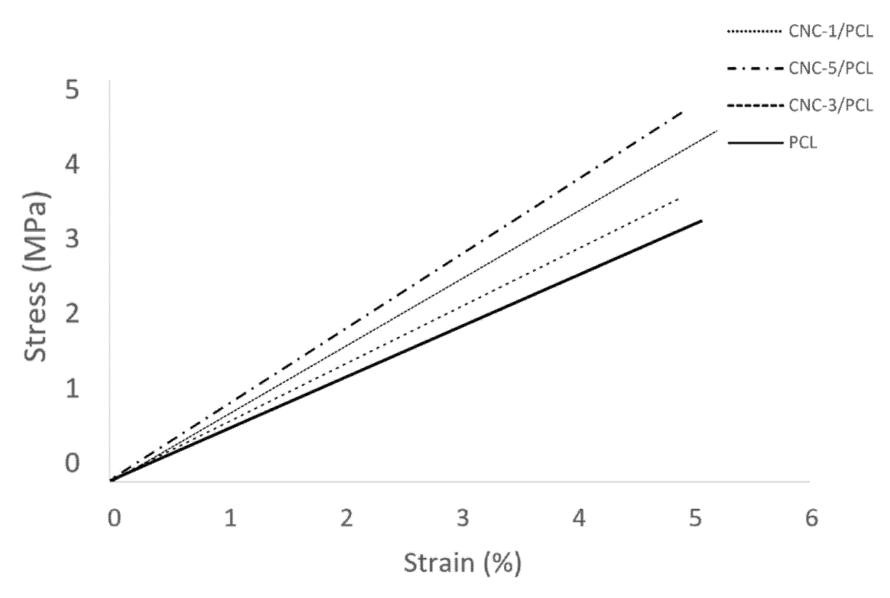
3.1.3. Analysis of the Mechanical Properties of the Materials

The strength and toughness of the material have become indispensable parameters for material selection, evaluation, and study of modification laws. Therefore, to investigate the effect of the addition of CNC on the mechanical properties of the CNC/PCL blended system, tensile tests were conducted on the samples with different CNC contents. As shown in Figure 7, when the content of CNC was increased to 1%, the tensile strength increased by 4% relative to PCL, and when the content of CNC was increased to 3%, the tensile strength increased by 13% relative to pure PCL. As the CNC content continues to increase, up to 5%, the tensile strength can reach 19%. This shows that the addition of CNC has an enhanced effect on the tensile properties of PCL, which is consistent with the results observed in XRD (see supplementary material Figure S5). When comparing the results of pure PCL, we can see that when CNC is added and the content is increased to a certain level, the enhancement effect of CNC is more obvious [37]. Therefore, it proves the feasibility of CNC/PCL materials in terms of mechanical properties, and the results have important reference significance for the study of self-healing properties of CNC/PCL blended systems.

3.2. Analysis of the SolidWorks Simulation Results

The deformation of the scaffold under tension or pressure is measured by the results obtained from the Solidworks simulation, as shown in Figure 8a,b. It can be seen that the maximum deformation of the scaffold is the maximum displacement of the scaffold surface.
Figure 8c shows the simulation results on the performance of the scaffold with different porosity of the concave hexagon filled scaffold: the maximum displacement and force of the relationship between different porosity is shown in the curve, which shows that the higher the porosity, the greater the maximum displacement of the scaffold with the same filled pattern and the same force, indicating that the mechanical properties of the scaffold are worse. In a direction vertical to the upper surface, the elastic modulus of the scaffold with 53.26% porosity is about 1.29 MPa. When the porosity is about 70.26%, the elastic modulus is reduced to about 0.57 MPa, about 56% lower.
As shown in Figure 8d,e, the elastic modulus can be regarded as an index to measure the difficulty of producing elastic deformation of the material. It is defined that the larger the elastic modulus was related to the greater stress that material undergoes a certain elastic deformation. For example, the larger value indicates the greater material stiffness; on the contrary, the smaller value indicates the better tensile property of the material. Therefore, it can be used as an indicator to evaluate the mechanical properties of the scaffolds, comparing the effects of different parameters and different filled patterns on the mechanical properties.
From Figure 8d,e, we can conclude that in the direction perpendicular to the upper surface, the concave hexagon filled pattern is at a higher position curve, while the triangular and orthogonal filled patterns are at a lower level. This means that in this direction, the scaffold printed with the concave hexagon filled pattern has a significantly higher modulus of elasticity and better vertical stiffness than the scaffold printed with the orthogonal and triangular filled patterns, which is suitable for some scaffolds that require a little stiffness in the longitudinal direction. With 60% porosity, the concave hexagon algorithm prints scaffolds with an elastic modulus of 1.04 MPa, while the modulus are respectively 0.72 MPa and 0.81 MPa when triangular algorithms and orthogonal algorithm are adopted, and in the direction parallel to the upper surface of the scaffold, the concave hexagon filled pattern is at the lowest point of the curve and there is no significant difference in the curves of the orthogonal and triangular filled patterns. It means that when the three filled patterns print scaffolds with the same porosity, the concave hexagon scaffold has the lowest modulus of elasticity and has better elasticity to cope with issues that need lateral directional deformation such as trachea or skin, so the concave hexagon filled pattern can print scaffolds with more anisotropic features.

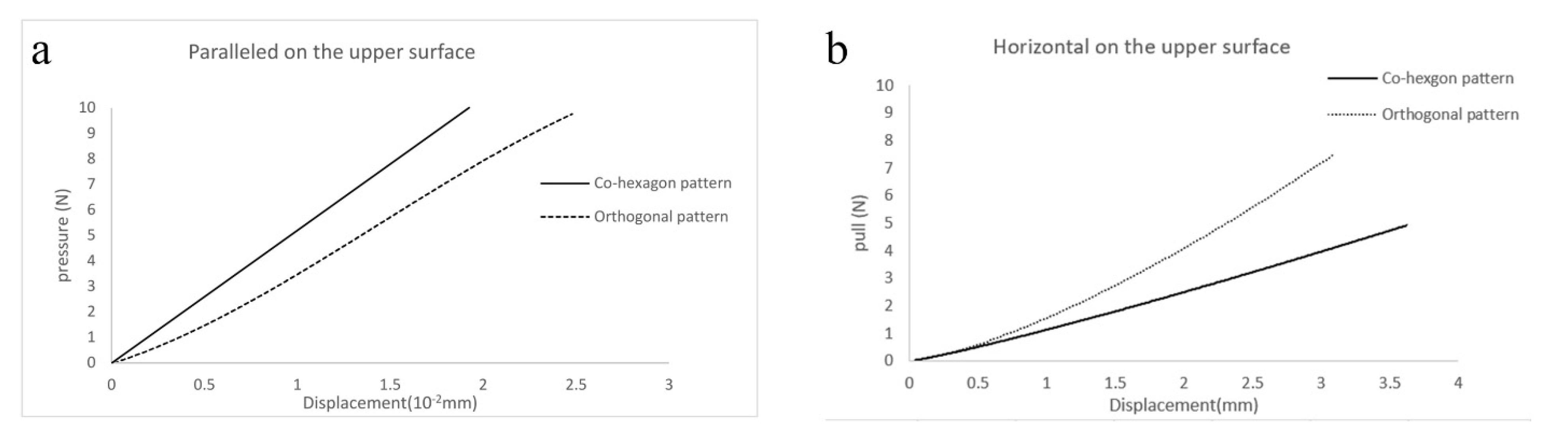
3.3. Analysis of the Simulation Results of the Different Scaffold Patterns

Figure 9 shows the velocity and pressure distribution of the nutrient and cell mixture flowing in the concave hexagon, orthogonal and triangular scaffolds with the same porosity. From the analysis of the pressure distribution diagrams in Figure 9a–c, it can be calculated that the average pressure of the concave hexagon is 87.26 Pa, while the average pressure of the orthogonal and triangular scaffolds reaches 314.83 Pa and 349.33 Pa, respectively. While the concave hexagon scaffolds have low pressure and resistance and good flow, which is suitable for the transport of cells and nutrients. From the velocity distribution diagram, the flow pattern is followed by the three different shapes of the scaffold flow field. By comparing the velocity distribution diagrams (d, e, f), the maximum flow velocity of the fluid in the orthogonal and triangular-shaped scaffold tubes reached 0.73 m/s and 0.74 m/s, respectively, with a large velocity difference, which is not conducive to the transport of cells and nutrient fluid and adversely affects the deposition of cells on the scaffold. The maximum flow velocity of the fluid in the concave hexagon scaffold tube was 0.505 m/s with a small velocity difference, which was very beneficial for the transport of cells and nutrient fluid [38]. To sum up the above analysis, in the range of this simulation, the concave hexagon fluid flow rate relatively uniform, and the average flow rate can basically reach 0.25 m/s, which is suitable for the transport of cells and nutrients, and the cells are also easy to deposit on the scaffold, which conducive to the growth of cells.

3.4. Structure Analysis of the Printed Cube Model

As shown in Figure 10a–c, three kinds of model drawings were printed by biological 3D printer (The optimal parameters of the printer see Table S1). Figure 10e–g is a top view of a structure with a 3D porous cube model printed with reasonable printing parameters using a triangular filled pattern, an orthogonal filled pattern, and a concave hexagon filled pattern. Figure 10g–i is a microscopic view of the orthogonal, triangular, and hexagon patterns under electron microscopy. It can be seen from Figure 10g–i that the cube model printed using the concave hexagon filled pattern consists of a large concave hexagon and a number of small holes, under the large concave hexagon to improve the porosity of the scaffold and the number of small holes to improve the mechanical properties of the scaffold.

3.5. Analysis of the Mechanical Properties of the Scaffolds

Since scaffolds have to have sufficiently high mechanical properties and the compressive tensile capacity varies with the porous structure, compressive tension experiments were designed to evaluate the mechanical properties of scaffolds with different filled patterns. Figure 11a shows the pressure-strain curves of the scaffolds using the same porosity orthogonal and concave hexagon filled patterns, since the scaffold material is nonlinear, its compression characteristic curve does not have the characteristics of the compression characteristic curve of the general linear elastic material. And the analysis shows that the compression characteristic curves of the porous scaffolds of different patterns are significantly different, the slope can be used to indicate the compressive properties. The concave hexagon curve has a slope of 5.207 is higher than the orthogonal filling pattern which has a slope of 4.069 so that the compressive properties of the concave hexagon figure are higher than the orthogonal filled figure, which indicates that this pattern of the scaffold is more rigid [39]. The tensile load-displacement curves of the orthogonal and concave hexagon scaffolds are shown in Figure 11b, and neither curve has a significant yield phase, indicating that the composite material prepared is not linear. And under the same force, the displacement of the concave hexagon is larger than that of the orthogonal one, so the concave hexagon filled pattern has a higher elasticity. Therefore, the material can be suitable for elastic tissue-engineered scaffolds requiring certain stiffness in the vertical direction and certain flexibility in the horizontal direction.

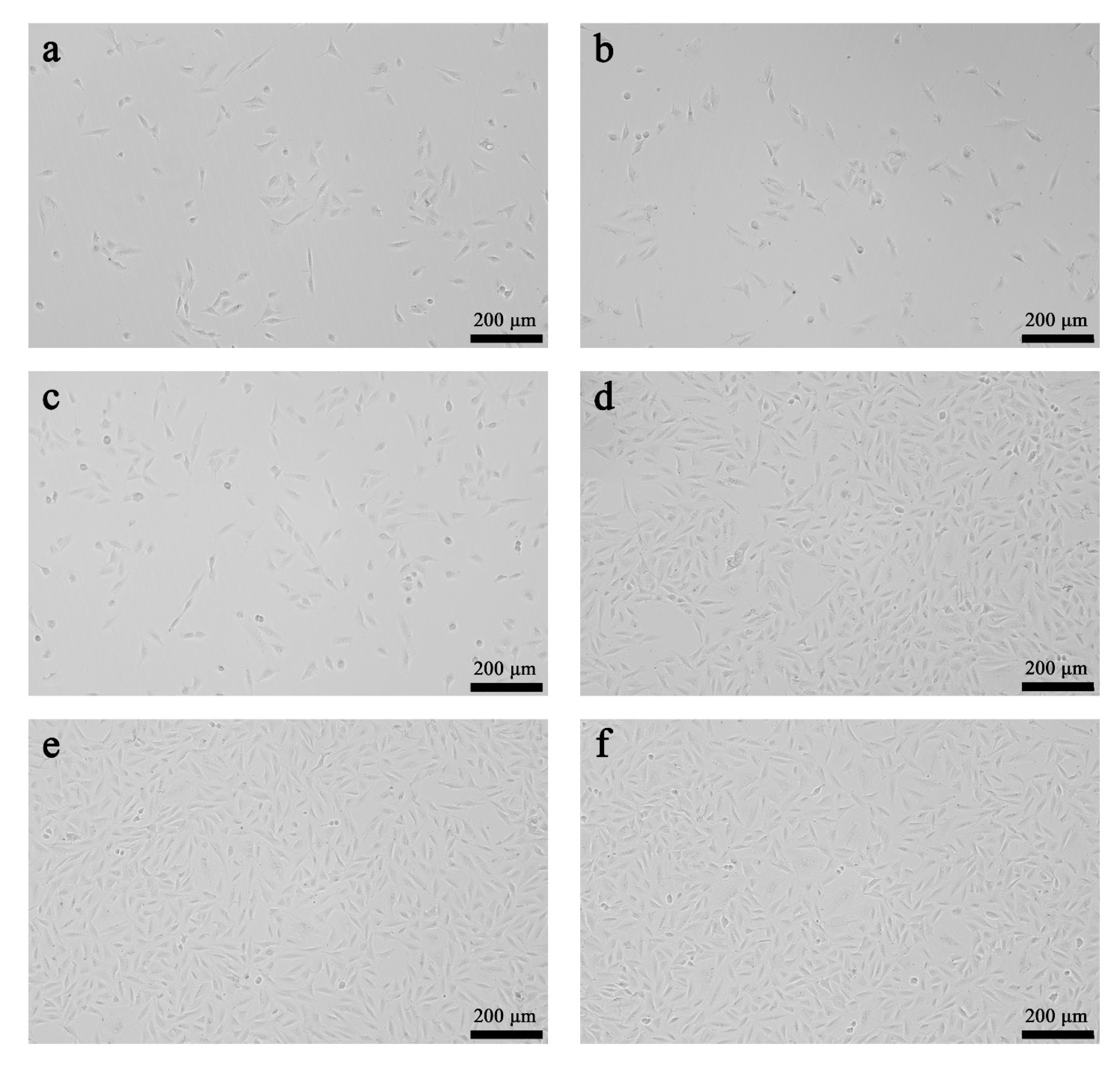
3.6. The Results of the Biocompatibility Assessment

In the cytotoxicity test of CCK-8 (Figure 12), the proliferation rate of MSCs cells in culture for 5 days in PCL, CNC-3/PCL, and control is shown in Figure 13. As shown in Figure 12, the relationship between absorbance and culture time. The absorbance value of scaffolds printed by PCL increases from 1.022 ± 0.22 to 1.759 ± 0.17 in 5 days while the absorbance value of scaffolds printed by CNC-3/PCL changes 1.005 ± 0.17 from to 1.67 ± 0.04. The absorbance value and cell growth trend of scaffolds do not differ significantly from those in the control. The result can prove that the scaffold can support the growth and proliferation of MSCs cells. The absorbance values of each well increased with increasing culture time, indicating that the number of cells on the scaffolds increased with increasing culture time. The daily absorbance values of the cells cultured on the scaffolds of the three groups were analyzed by one-way ANOVA using Graphpad prism 5. 0 software, and the absorbance of the same number of cells cultured in normal culture medium was used as the control group, and the results showed that the absorbance values of each well were not statistically different (p > 0.05) [40]. It indicates that the cell proliferation rate is comparable in the three solvent groups, with increasing culture time. And there was no change in cytotoxicity of CNC/PCL composites when compared with PCL.
It was observed in Figure 13 that the differentiation of MSCs cells with PCL, CNC-3/PCL, and control group for 1 day (a,b,c) and 5 days (d,e,f). After 1d, there were few MSCs, small in size, growing in clusters, with different morphologies, mostly shuttle-shaped. 5d later, the number of MSCs increased, and the cell morphologies were varied, including round, shuttle-shaped, irregularly shaped, etc., and were arranged in an orderly manner. This phenomenon indicated that MSCs cells grew well in the scaffold.

4. Conclusions

In tissue engineering, using melt-extruded 3D printing with oxidized nanocellulose and polycaprolactone as printing materials is a feasible and effective method for the preparation of scaffolds. The scaffolds made by this method have anisotropic mechanical properties and porous structures to meet the needs of cell proliferation, differentiation, and angiogenesis. The 3D printing process of porous scaffolds using specially formulated nanocellulose and polycaprolactone as printing material has been discussed in detail. The biological and mechanical properties of this composite material were tested by SEM and DMA, showing a concave hexagon stacked filled pattern. The physical and mechanical properties of the 3D model of the scaffolds were simulated using Solidworks, and the ANSYS FLUENT was performed to simulate the flow of cellular fluid in the scaffold. After several experiments to select the optimal parameters of printing the porous scaffold pattern and measuring the compression and elastic properties, CCK8 cytotoxicity experiments were performed on the bio-printed material. The results in this study demonstrate that the CNC-added composites have higher biological and mechanical properties than the pure PCL materials and possess good biocompatibility. The concave hexagon filled pattern for 3D printing can also significantly affect the porosity and mechanical properties of the scaffold. The proposed concave hexagon filled pattern can reduce the overlap length of the printed scaffold, ensuring an ideal porosity for better molding. With the same porosity, the concave hexagon has better compression resistance in the vertical direction and tensile properties in the horizontal direction as far as the mechanical properties are concerned. Therefore, it can be concluded that the composite and concave hexagon filled patterns are well suited for 3D printing of biological tissue stack formation and can be widely used in the preparation of various tissues and organs.

Supplementary Materials

The following are available online at https://www.mdpi.com/2076-3417/11/3/1273/s1, Figure S1: TEM image of cellulose nanocrystal. Scale bar is 200 nm. Figure S2: Printability Analysis of Composites with different mixing ratios. Figure S3: Tensile hardness tester. Figure S4: Layout diagram of strain gauge. Figure S5: XRD scanning pattern of PCL/CNC nanocomposites with various amounts of CNC. Table S1: The optimal parameters when printing different filling patterns.

Author Contributions

Manuscript writing C.F.; resources, H.S. and G.Z.; manuscript editing, Y.J.; funding acquisition J.Z.; software X.X. All authors have read and agreed to the published version of the manuscript.

Funding

This work was supported financially by the National Natural Science Foundation of China (No. 81770018) and Yangzhou—Yangzhou University Science and Technology Cooperation Project (No. SCX2017020015).

Conflicts of Interest

The authors declare no conflict of interest.

References

  1. Jing, X.; Peng, X.F. Research progress in preparation of biodegradable polymer porous scaffolds. China Plast. 2012, 26, 1–6. [Google Scholar] [CrossRef]
  2. Johnson, C.; Sheshadri, P.; Ketchum, J.M.; Narayanan, L.K.; Weinberger, P.M.; Shirwaiker, R.A. In vitro characterization of design and compressive properties of 3D-biofabricated/decell ularized hybridgrafts for tracheal tissue engineering. Mech. Behav. Biomed. Mater. 2016, 59, 572–585. [Google Scholar] [CrossRef] [PubMed]
  3. Park, J.H.; Jung, J.W.; Kang, H.W.; Joo, Y.H.; Lee, J.S.; Cho, D.W. Development of a 3D bellows tracheal graft: Mechanical behavior analysis, fabrication and an in vivofeasibility study. Biofabrication 2012, 4, 035004. [Google Scholar] [CrossRef]
  4. Kuehn, B.M. Clinicians Embrace 3D Printers to Solve Unique Clinical Challenges. JAMA 2016, 315, 333–335. [Google Scholar] [CrossRef] [PubMed]
  5. Yoo, D. New paradigms in hierarchical porous scaffold design for tissue engineering. Mater. Sci. Eng. C Mater. Biol. Appl. 2013, 33, 1759–1772. [Google Scholar] [CrossRef]
  6. Li, J.; Chen, M.; Fan, X.; Zhou, H. Recent advances in bioprinting techniques: Approaches, applications and future prospects. J. Transl. Med. 2016, 14, 271–275. [Google Scholar] [CrossRef] [Green Version]
  7. Goetzendorfer, B.; Mohr, T.; Hellmann, R. Hybrid Approaches for Selective Laser Sintering by Building on Dissimilar Materials. Materials 2020, 13, 5285. [Google Scholar] [CrossRef]
  8. Korpela, J.; Kokkari, A.; Korhonen, H.; Malin, M.; Närhi, T.; Seppälä, J. Biodegradable and bioactive porousscaffold structures prepared using fused deposition modeling. J. Biomed. Mater. Res. Part B Appl. Biomater. 2013, 101, 610–619. [Google Scholar] [CrossRef]
  9. Bourell, D.; Espalin, D.; Arcaute, K.; Rodriguez, D.; Medina, F.; Posner, M.; Wicker, R. Fused deposition modeling of patient-specific polymethylmethacrylate implants. Rapid Prototyp. J. 2010, 16, 164–173. [Google Scholar] [CrossRef]
  10. Luong, D.X.; Subramanian, A.K.; Lopez Silva, G.A.; Yoon, J.; Cofer, S.; Yang, K.; Owuor, P.S.; Wang, T.; Wang, Z.; Lou, J.; et al. Laminated Object Manufacturing of 3D-Printed Laser-Induced Graphene Foams. Adv. Mater. 2018, 30, 1707416. [Google Scholar] [CrossRef]
  11. Ahn, D.; Kweon, J.H.; Choi, J.; Seokhee, L. Quantification of surface roughness of partsprocessed by laminated object manufacturing. J. Mater. Process. Technol. 2012, 212, 339–346. [Google Scholar] [CrossRef]
  12. Melchels, F.P.W.; Feijen, J.; Grijpma, D.W. A review on stereolithography and itsapplications in biomedical enginccring. Biomaterials 2010, 31, 6121–6130. [Google Scholar] [CrossRef] [PubMed] [Green Version]
  13. Arcaute, K.; Mann, B.K.; Wicker, R.B. Practical use of hydrogels in stereolithography for tissue engineering applications. In Stereolithography; Springer: Boston, MA, USA, 2011; pp. 299–331. [Google Scholar] [CrossRef]
  14. Anne, G.; David, B.V.; Carlos, B.P.J.; Marcos, L.; Ana, A.P.; Abad, J.L.M. Experimental and Numerical Investigation of the Extrusion and Deposition Process of a Poly(lactic Acid) Strand with Fused Deposition Modeling. Polymers 2020, 12, 2885. [Google Scholar] [CrossRef]
  15. Ghosal, K.; Manakhov, A.; Zajíčková, L.; Thomas, S. Structural and surface compatibility study of modified electrospun poly(ε-caprolactone) (PCL) composites for skin tissue engineering. AAPS PharmSciTech 2017, 18, 72–78. [Google Scholar] [CrossRef] [PubMed] [Green Version]
  16. Cho, S.J.; Jung, S.M.; Kang, M.; Shin, H.S.; Youk, J.H. Preparation of hydrophilic PCL nanofiber scaffolds via electrospinning of PCL/PVP-b-PCL block copolymers for enhanced cell biocompatibility. Polymer 2015, 69, 95–102. [Google Scholar] [CrossRef]
  17. Li, Z.; Tan, B.H. Towards the development of polycaprolactone based amphiphilic block copolymers: Molecular design, self-assembly and biomedical applications. Mater. Sci. Eng. C 2014, 45, 620–634. [Google Scholar] [CrossRef]
  18. Cobos, M.; Ramos, J.R.; Guzmán, D.J.; Fernández, M.D.; Fernández, M.J. PCL/POSS Nanocomposites: Effect of POSS Derivative and Preparation Method on Morphology and Properties. Polymers 2018, 11, 33. [Google Scholar] [CrossRef] [Green Version]
  19. Propst, E.J.; Prager, J.D.; Meinzen-Derr, J.; Clark, S.L.; Cotton, R.T.; Rutter, M.J. Pediatric tracheal reconstruction using cadaveric homograft. Arch. Otolaryngol. Head Neck Surg. 2011, 137, 583–590. [Google Scholar] [CrossRef] [Green Version]
  20. Delaere, P.; Vranckx, J.; Verleden, G.; Leyn, P.D.; Raemdonck, D.V. Leuven Tracheal Transplant Group Tracheal allotransplantation after withdrawal of immunosuppressive therapy. N. Engl. J. Med. 2010, 362, 138–145. [Google Scholar] [CrossRef]
  21. Wurtz, A.; Hysi, I.; Kipnis, E.; Copin, M.C. Recent Advances in Circumferential Tracheal Replacement and Transplantation. Am. J. Transplant. 2016, 16, 1334–1335. [Google Scholar] [CrossRef] [Green Version]
  22. Ma, T.; Lv, L.; Ouyang, C.; Hu, X.; Liao, X.; Song, Y.; Hu, X. Rheological behavior and particle alignment of cellulose nanocrystal and its composite hydrogels during 3D printing. Carbohydr. Polym. 2021, 253, 117217. [Google Scholar] [CrossRef] [PubMed]
  23. Zhou, C.; Shi, Q.; Guo, W.; Terrell, L.; Qureshi, A.T.; Hayes, D.J.; Wu, Q. Electrospun bio-nanocomposite scaffolds for bone tissue engineering by cellulose nanocrystals reinforcing maleic anhydride grafted PLA. ACS Appl. Mater. Interfaces 2013, 5, 3847–3854. [Google Scholar] [CrossRef]
  24. Huan, W.L.; Cheng, L.; Bai, G.; Liu, G. Fabrication and characterization of electrospun polystyrene/cellulose nanocrystals nanofibrous films. Polym. Mater. Sci. Eng. 2016, 32, 141–146. [Google Scholar] [CrossRef]
  25. Baguneid, M.S.; Seifalian, A.M.; Salacinski, H.J.; Murray, D.; Hamilton, G.; Walker, M.G. Tissue engineering of bloodvessels. Br. J. Surg. 2006, 93, 282–290. [Google Scholar] [CrossRef] [PubMed]
  26. Dias, D.; Vale, A.C.; Cunha, E.P.F.; Paiva, M.C.; Reis, R.L.; Vaquette, C.; Alves, N.M. 3D-printed cryomilled poly(ε-caprolactone)/graphene composite scaffolds for bone tissue regeneration. J. Biomed. Mater. Res. B Appl. Biomater. 2020. [CrossRef]
  27. Aliabouzar, M.; Lee, S.J.; Zhou, X.; Zhang, G.L.; Sarkar, K. Effects of scaffold microstructure and low intensity pulsed ultrasound on chondrogenic differentiation of human mesenchymal stem cells. Biotechnol. Bioeng. 2018, 115, 495–506. [Google Scholar] [CrossRef]
  28. Zhang, W.; Zhao, S.; Sun, R.; Scarpa, F.; Wang, J. Research and application of mechanical properties of negative Poisson’s ratio materials and structures. Prog. Mech. 2011, 41, 335–350. [Google Scholar] [CrossRef] [Green Version]
  29. Ingrole, A.; Hao, A.; Liang, R. Design and modeling of auxetic and hybrid honeycomb structures for in-plane property enhancement. Mater. Des. 2017, 117, 72–83. [Google Scholar] [CrossRef]
  30. Jiang, Y.; Zhou, J.; Zhang, Q.G.; Zhao, L.; Heng, D.; Chen, D.; Liu, D. Preparation of cellulose nanocrystals from Humulus japonicus stem and the influence of high temperature pretreatment. Carbohydr. Polym. 2017, 164, 284–293. [Google Scholar] [CrossRef]
  31. Ferrua, M.J.; Xue, Z.; Singh, R.P. On the kinematics and efficiency of advective mixing during gastric digestion—A numerical analysis. J. Biomech. 2014, 47, 3664–3673. [Google Scholar] [CrossRef]
  32. Zhou, J.; Feng, C. Nanocomposite Gel Material Hardness and Stretch Automatic Detector. CN209690061U, 26 November 2019. [Google Scholar]
  33. Xu, X.; Zhou, J.; Jiang, Y. 3D printing process of oxidized nanocellulose and gelatin scaffold. J. Biomater. Sci. Polym. Ed. 2018, 29, 1498–1513. [Google Scholar] [CrossRef] [PubMed]
  34. Mi, H.Y.; Jing, X.; Peng, J.; Salick, M.R.; Peng, X.F.; Turng, L.S. Poly(ε-caprolactone) (PCL)/cellulose nano-crystal (CNC) nanocomposites and foams. Cellulose 2014, 21, 2727–2741. [Google Scholar] [CrossRef]
  35. Feng, Q.; Yamasaki, N.; Yanagisawa, K. Hydrothermal syn-thesis and metal ion adsorptive property of birnessite-type po-tassium manganese oxide. J. Mater. Sci. Lett. 1996, 15, 963–965. [Google Scholar] [CrossRef]
  36. Alvesda, S.M.; Crawford, A.; Mundy, J.M. Chitosan/polyester-based scaffolds for cartilage tissue engineering: Assessment of extracelluar matrix formation. Acta Biomater. 2010, 6, 1149–1157. [Google Scholar] [CrossRef] [Green Version]
  37. Domingues, R.M.; Chiera, S.; Gershovich, P. Enhancing the biomechanical performance of anisotropic nanofibrous scaffolds intendon tissue engineering: Reinforcement with cellulose nanocrystals. Adv. Healthc. Mater. 2016, 5, 1364–1375. [Google Scholar] [CrossRef]
  38. Xu, S.L.; Li, T.C.; Lu, B.H. Numerical study of two-phase flow of cells and cell suspension in microchannels during artificial bone perfusion in vitro. J. Mech. Eng. 2006, 3, 40–45. [Google Scholar] [CrossRef]
  39. Guo, Y.J.; Yuan, M.Q.; Qian, X.M. Mechanical behavior and response characteristics of concave honeycomb structures under impact loading. J. Beijing Inst. Technol. 2019, 15, 5–10. [Google Scholar]
  40. Saeedi, R.; Omrani, L.R.; Abbasi, M.; Chiniforush, N.; Kargar, M. Effect of Three Wavelengths of Diode Laser on the Efficacy of Bleaching of Stained Teeth. Front. Dent. 2019, 16, 458–464. [Google Scholar] [CrossRef]
Figure 1. Layer of concave hexagons (a) and a stack of concave hexagons (b).
Applsci 11 01273 g001
Figure 2. Three different fill structures (ac).
Applsci 11 01273 g002
Figure 3. Simulation model (a) with pressure perpendicular to the upper surface of the scaffold (b) and tension parallel to the upper surface of the scaffold (c).
Applsci 11 01273 g003
Figure 4. Three different patterns of fluid simulation models with concave hexagon (a), triangle (b), and orthogonal (c).
Applsci 11 01273 g004
Figure 5. SEM phase morphology of (a) neat PCL, (b) CNC-1/PCL, (c) CNC-3/PCL, and (d) CNC-5/PCL samples.
Applsci 11 01273 g005
Figure 6. Variation of viscosity with shear rate (a), the storage modulus (b), and loss modulus(c) as a function of angular frequency in pure PCL and PCL/CNC composites with different contents of CNC.
Applsci 11 01273 g006
Figure 7. Tensile properties of different materials.
Applsci 11 01273 g007
Figure 8. Simulation results for the scaffold of different filled structures: deformation in the direction perpendicular to the upper surface (a) or parallel to the upper surface (b), stress-strain curves for different pores (c), and elastic modulus versus porosity in both directions (d,e).
Applsci 11 01273 g008
Figure 9. Velocity distribution of different filled structures at the same porosity (ac) Pressure distribution (df).
Applsci 11 01273 g009
Figure 10. Printed cube model using different fill patterns (ac), printed cube model (df) and microscope photographs of the printed cube model (gi).
Applsci 11 01273 g010
Figure 11. Pressure-displacement curves for orthogonal and hexagonal scaffold (a) and tension-displacement curves for orthogonal and hexagonal scaffold (b).
Applsci 11 01273 g011
Figure 12. Results of CCK-8 cytotoxicity test.
Applsci 11 01273 g012
Figure 13. Images of MSCs cells on day 1 and day 5 of culture in PCL (a,d), CNC-3/PCL (b,e), and control (c,f).
Applsci 11 01273 g013
Table 1. Chemical compositions of samples2.2.2 Simulation Modeling of a different scaffold pattern.
Sample NameSpecific Gravity of Dry CNC (%)Specific Gravity of Dry PCL (%)
PCL0100
CNC-1/PCL199
CNC-3/PCL397
CNC-5/PCL595
Publisher’s Note: MDPI stays neutral with regard to jurisdictional claims in published maps and institutional affiliations.

