1. Introduction
Generation of pulsed nanosecond THz radiation in the frequency range of 0.3–30 THz at a difference frequency with an average power of ≈1–10 mW is an intensively developing area of laser technology and nonlinear optics [
1,
2]. Effective parametric generation at the difference frequency requires the use of nonlinear crystals with high optical transparency at all wavelengths—pumping, signal, and idler waves; a large second-order nonlinear susceptibility; high laser-induced damage threshold (LIDT); and good spatial homogeneity. The negative uniaxial GaSe crystal is one of the most famous and demanded nonlinear crystals in terms of its characteristics among the extensive variety of nonlinear optical crystals for oscillating THz radiation [
1]. The transparency is in the range of 0.65–18 μm. The absorption coefficient of this single crystal amounts to ≈0.1 cm
−1 at a wavelength of ≈2 μm [
3], and, alongside ZnGeP
2, it is characterized by the lowest absorption among all nonlinear crystals in the THz spectral range (90–1000 μm) [
4]. The material has high birefringence, nonlinear susceptibility of GaSe is ≈54 pm/V [
3], and high thermal conductivity reaching ≈16 W m
−1 K
−1 (which allows for phase matching to be carried out over a wide range). GaSe has a layered structure along the
C axis. Weak Van der Waals forces occur between the layers, while strong covalent bonds and an ionic component are inside the layers. Such structure makes the material soft with the Mohs hardness [
3] of ≈1. This is the main disadvantage of GaSe. GaSe samples are difficult to cut at various angles to the
C axis and polish. Therefore, in almost all known devices, GaSe crystals are made by splitting, and the working surfaces are parallel to the c-face.
The use of a dual-wavelength degenerate optical parametric oscillator (OPO) based on a nonlinear KTP crystal with intracavity pumping by Nd
3+:YAG laser as a pumping source is one of the most effective ways to generate powerful tunable THz radiation at a difference frequency in nonlinear crystals including GaSe [
5]. These sources are capable of generating powerful tunable dual-wavelength radiation with an orthogonal polarization near the degeneration point of 2.12 μm with an average power of ≈10 W and a pulse power of ≈100 KW at a pulse repetition rate of ≈1–10 kHz and a pulse duration of ≈10–20 ns [
6,
7,
8]. The most efficient nonlinear crystals for generating THz radiation, such as GaSe and ZnGeP
2, have minimum absorption in this wavelength range, which compares favorably this pump source with dual-wavelength tunable (or with a discrete set of wavelengths) systems operating in the spectral region of ≈1 μm or ≈10 microns.
The problem of GaSe damage by laser radiation at the wavelengths of 1–10 μm was covered in several previously published works [
9,
10,
11,
12]. In particular, these works described that in terms of the intensity of the acting beam at a wavelength of 9.55 µm, the GaSe LIDT was 121 MW/cm
2 with pulse duration of ≈30 ns and the repetition rate of 1 Hz [
9].
In Reference [
12], GaSe LIDT was studied when exposed to radiation from the following lasers: Ti:Sapphire laser (λ-800 nm, pulse duration—100 fs); frequency-tunable optical parametric amplifier (λ-1.1–2.9 μm, pulse duration—60–90 fs); TEA (Transversely Excited Atmospheric) CO
2 laser (λ-10.6 μm, pulse duration—50 ns); Er
3+:YSGG laser (λ-2.79 μm, pulse duration—250 ns). It was shown that when GaSe is exposed to femtosecond radiation, the local microdefects and the induced field effects—for example, dissociation of GaSe and multiphoton absorption—have strong impact on LIDT. It is also noted that under the influence of pulse nanosecond laser radiation, the thermal effects have a considerable influence on GaSe LIDT.
However, there is currently no sufficient information on LIDT of a nonlinear GaSe crystal when exposed to laser radiation in a repetitively pulsed mode at pulse repetition rates of ≈10 kHz and higher at exposure wavelengths of ≈2.1 μm and pulse durations of ≈20 ns and lower. This hinders the progress in generating THz radiation at a difference frequency in nonlinear GaSe crystals and does not allow for determination of the optimal energy parameters of pump radiation for the conditions of the most efficient generation of THz irradiation. Moreover, there are insufficient data on the effect of various technological processes on GaSe damage threshold in the wavelength range of ≈2.1 μm, including doping of crystals with chemical elements such as In.
The purpose of the paper is to determine LIDT of GaSe and GaSe:In single crystals upon exposure to nanosecond radiation in the two-micron range and to assess the influence of pump radiation energy parameters (pulse repetition rate, pulse duration) on the damage threshold. The obtained data are proposed to be used for the subsequent optimization of the pump radiation energy parameters (in the wavelength range of ≈2.1 μm) of THz sources based on difference frequency generation using GaSe and GaSe:In crystals.
2. Test Samples and Research Technique
Two crystals GaSe (sample no. 1) and GaSe:In (sample no. 2) produced by Harbin Institute of Technology, China, were used as the test samples. Sample no. 2 was doped with In. The thickness of sample no. 1 was 3.1 mm, the sample aperture was 8 × 5 mm2 (rectangle), the thickness of sample No. 2 was 4.49 mm, and the sample aperture was 5 × 7 mm2. The working surfaces of the samples were orthogonal to the optical axis of the crystal.
Se (6N) and Ga (6N) were used for GaSe synthesis. They were purified firstly in Aqua Regia and then carefully washed in distilled water fused silica ampules, and pyrolytic boron nitride (PBN) loads and crucibles were used for synthesis and growth. The ampules with substances were pumped down 10−5 mm Hg. The single-temperature method was applied for synthesis. GaSe crystals with a diameter of 30 and 40 mm were grown by vertical Bridgeman (VB) method. The high-temperature zone was 1075 °C and the low-temperature zone was 920 °C. The temperature gradient was 4 deg/cm and the pulling rate was 0.5 mm/h.
The surface roughness of both samples was identical and was determined using a Bruker Dimension Edge atomic force microscope (AFM). AFM scanning of the samples was carried out on the area of 10 × 10 µm at room temperature. The result of determining the surface roughness of sample no. 1 is shown in
Figure 1.
Figure 1 shows that the maximum difference in height and depth of inhomogeneities on the surface of the samples was 6 nm.
A Ho
3+:YAG laser developed at the IAP RAS was used as a source of laser radiation. Lasing was carried out at a wavelength of 2.091 μm (close to the radiation wavelength of 2.12 μm produced in the process of degenerate parametric generation based on a KTP crystal) [
13]. Lasing was carried out in the active Q-switching mode using an acousto-optic modulator with pulse duration τ equal to 15, 18, 20, or 23 ns, depending on the pulse repetition rate f equal to 10, 12, 14, or 20 kHz, respectively. To avoid changes in the pulse duration and the intensity distribution in the cross section of the generated beam, we pumped the Ho
3+:YAG laser with a thulium fiber laser with a fixed average power of 50 W. The maximum average radiation power generated by the Ho
3+:YAG laser was 30 W in a linearly polarized high-quality Gaussian beam (M
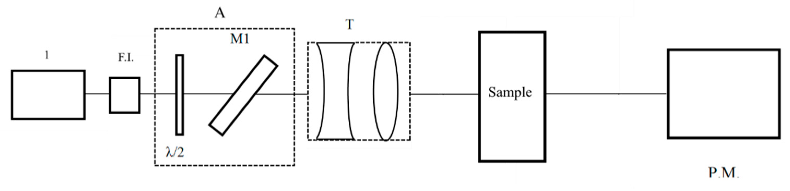
2 was less than 1.2). The scheme of the test setup is shown in
Figure 2. The stand consisted of the following elements: 1—Ho
3+:YAG laser; F.I.—Faraday optical isolator; A—attenuator, which was used to adjust the power level (consisted of a half-wave plate and a polarizing mirror M1 with high transmittance in p—polarization and high reflection in s—polarization); T—two-lens Galilean telescope focusing radiation on the test samples; Sample—sample under study fixed in a holder, adjusted in angle and transverse coordinates; P.M.—power meter. The average radiation power
Pa was measured using a power meter immediately before installation of the test samples. The studied plates were deviated from the position corresponding to normal incidence by 3–5° to prevent the reflected radiation from entering the laser exit window.
The diameter of the laser beam at the 1/e
2 level in the plane corresponding to the entrance aperture of the tested plate was measured by the Foucault knife-edge test according to the technique described in [
14,
15]. The diameter of the radiation beam measured in the knife plane (sample installation) was d = (280 ± 10 μm) at the 1/e
2 level.
Figure 3 shows the intensity distribution over the laser beam diameter. According to the international standard International Organization for Standardization (ISO) 21254, the effective area of the Gaussian beam is S = πd
2/4 [
15]. The laser fluence was determined by Equation (1):
The laser power density was determined by Equation (2):
3. Results
There are two main mechanisms of optical damage of nonlinear crystals accompanied by accumulative effects. The first is caused by thermal heating of the material when absorbing laser radiation with volumetric defects. The volumetric defects, as well as the defect-matrix medium boundary, may have an absorption coefficient significantly higher than the matrix medium, and may cause optical damage being heated to the melting point when absorbing laser radiation. Thus, at a high frequency of laser radiation pulses, the absorption heating may exceed the heat removal from the defect due to the thermal conductivity of the material and cause an “accumulative effect”, leading to material breakdown. The second proposed mechanism is nonlinear absorption associated with the transition of charge carriers to impurity levels for example, formed by point defects, under the influence of laser radiation. The point defects caused by the incorporation of impurity atoms into the crystal lattice or the formation of vacancies and the substitution of atoms of the original semiconductor components may be the sources of impurity levels in the semiconductor. Due to the transition of free charge carriers to impurity levels the absorption may increase many times as the intensity of laser radiation increases. This may result in the material being heated to temperatures above the melting point and, as a result, to the optical damage.
To assess the effect of volumetric defects on the optical damage threshold, we determined the presence or absence, as well as the geometry of volumetric defects, in all tested samples through using the digital holography. To assess the effect of point defects on the optical damage threshold, we measured the absorption at the wavelength of exposure radiation (since the presence of point defects leads to the formation of impurity levels in the band gap, which may significantly affect the absorption coefficient at the exposure wavelength).
The study of LIDT was preceded by recording the digital holograms of the test samples using a 1.064 μm digital holographic camera (DHC) manufactured by LLC Laboratory of Optical Crystals. Computer reconstruction of holographic images was carried out from the recorded holograms in order to determine internal inhomogeneities and volumetric defects. The limiting resolution of the method was 15 μm. A detailed description of the digital holography technique and a description of the setup are given in [
16,
17].
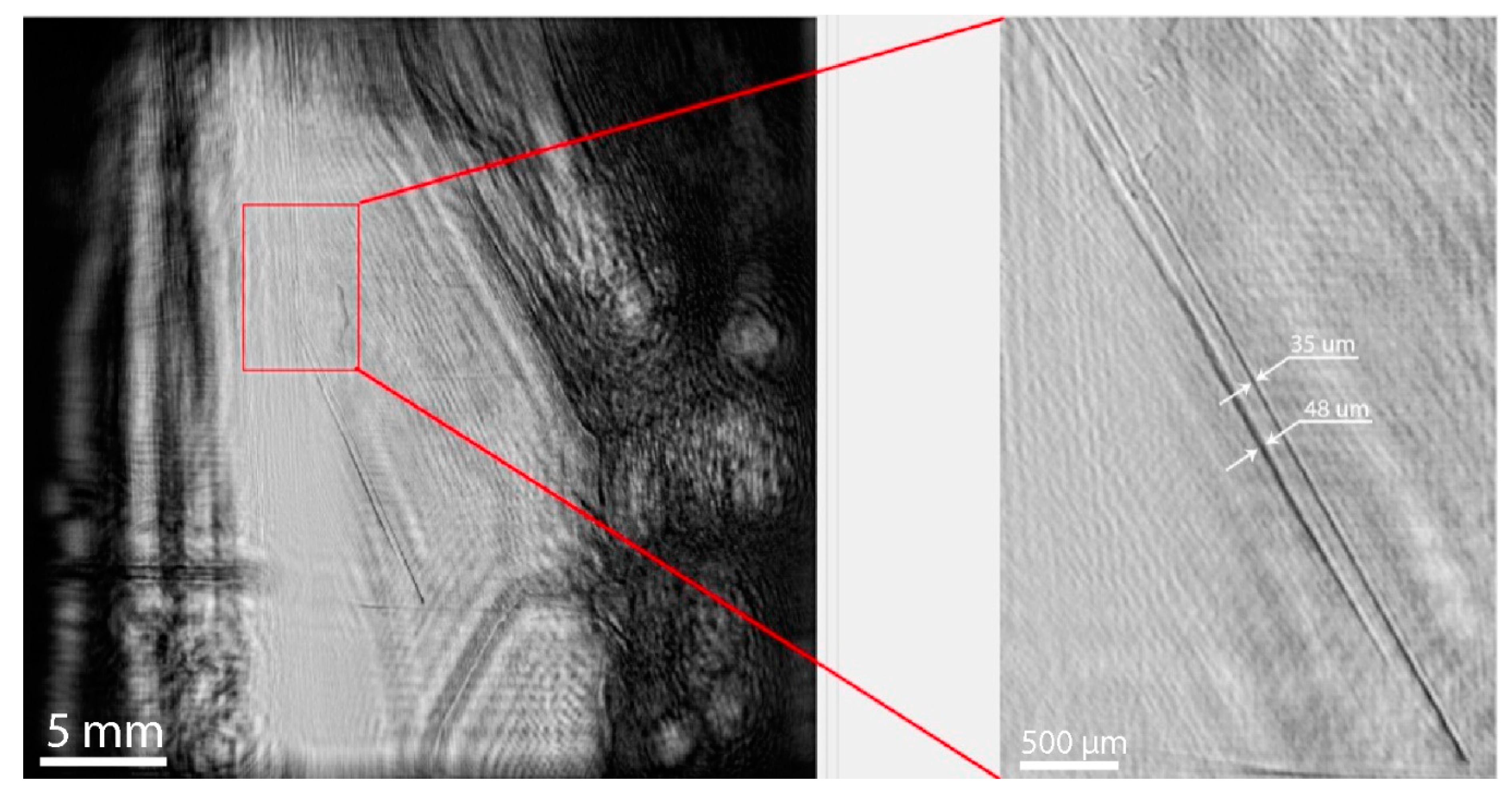
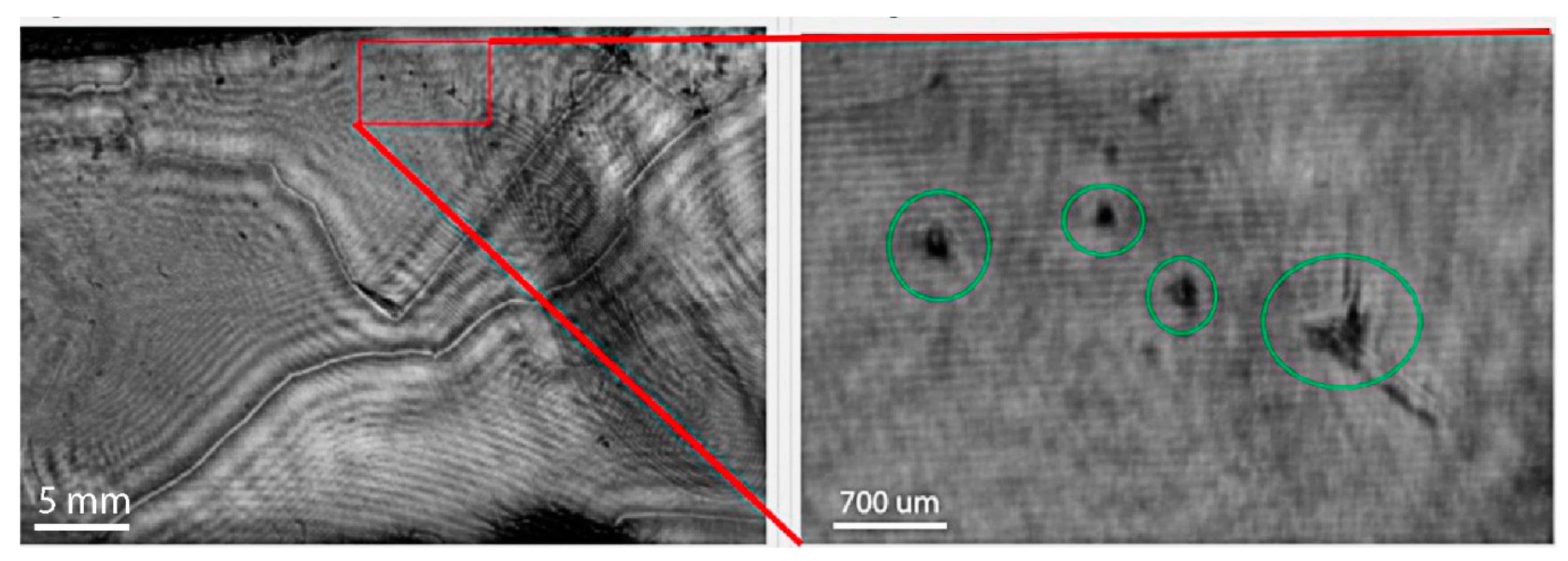
According to the results of the holographic test, the GaSe (sample no. 1) did not contain any inclusions and volumetric defects except for the microcracks shown in
Figure 3. However, volumetric inclusions with a size of ≈300 μm were found in GaSe:In (sample no. 2) (
Figure 4).
Then, the transmittance of both samples was measured, and the absorption was calculated, taking into account multiple reflections from the plane-parallel faces of the plates at a wavelength of 2.091 μm. The beam reflection losses in GaSe sample were calculated using dispersion equations for refractive index of ordinary and extraordinary waves obtained in the study [
18]. The following results presented in
Table 1 were obtained by determining the transmittance at a wavelength of 2.091 μm and calculating the absorption.
The R-on-1 method [
19] was used to determine LIDT since the aperture of the samples under study was limited in the given experiment. The key principle of the R-on-1 technique is that each separate region of the crystal is exposed to laser radiation with a gradual increase in the laser radiation intensity until the occurrence of an optical damage or a given value of the energy density is reached [
20]. The testing of samples for LIDT using the R-on-1 technique included the exposure of the studied plate to pulsed laser radiation with a fixed fluence level during the exposure time of 1 s. Further, the fluence was increased with a step of 0.1 J/cm
2. The fact of the optical damage was established by the appearance of a glow in the area of exposure and a decrease in radiation transmission, as well as upon appearance of a damage on one of the crystal surfaces. Then, the sample was moved 0.7 mm in height or horizontally using a two-coordinate movement, and the experiment was repeated. The measurements were taken five times in order to obtain statistical data.
Figure 5 shows the surfaces of GaSe samples with traces of the optical damage. The obtained experimental data served as a basis for constructing a graph of the cumulative probability of an optical damage depending on the fluence of the laser action. The point with the maximum fluence at which the damage occurred was assigned the probability P
D = (5/5) = 1; the point with the lower fluence value was assigned the probability P
D = (4/5) = 0.8, etc.; and the point with the minimum fluence value was assigned the probability—P
D = (1/5) = 0.2. Then, the experimental data were linearly approximated to the zero value of the optical damage probability. The fluence value of the incident radiation corresponding to the zero probability of the optical damage P
D = 0 was taken as the damage threshold W
0d. The average value of the optical damage fluence was also calculated by using Equations (3)–(6):
and mean square error:
where
N—total number of damaged sections,
—average value of the damage threshold,
Wi—value of the damage threshold at one of
N points, and
ni—number of points with the damage threshold
Wi.
The following formula was used to find the confidence interval for LIDT (
WD):
where
k—Student’s coefficient. Student’s
t-distribution was used for the confidence probability Equation (5) [
20,
21]:
where Γ—gamma function.
After the absorption of the samples was determined, LIDT values were obtained for each sample in terms of the fluence
and the peak power
of laser radiation at the probability of laser-influenced damage P
D = 0, according to the method described above. The average fluence
and the peak power
of the test radiation were found using Equations (1)–(5), at which the laser-induced damage of the sample took place. The confidence interval of LIDT in terms of the fluence
and the peak power
was also obtained. The experimental results are shown in
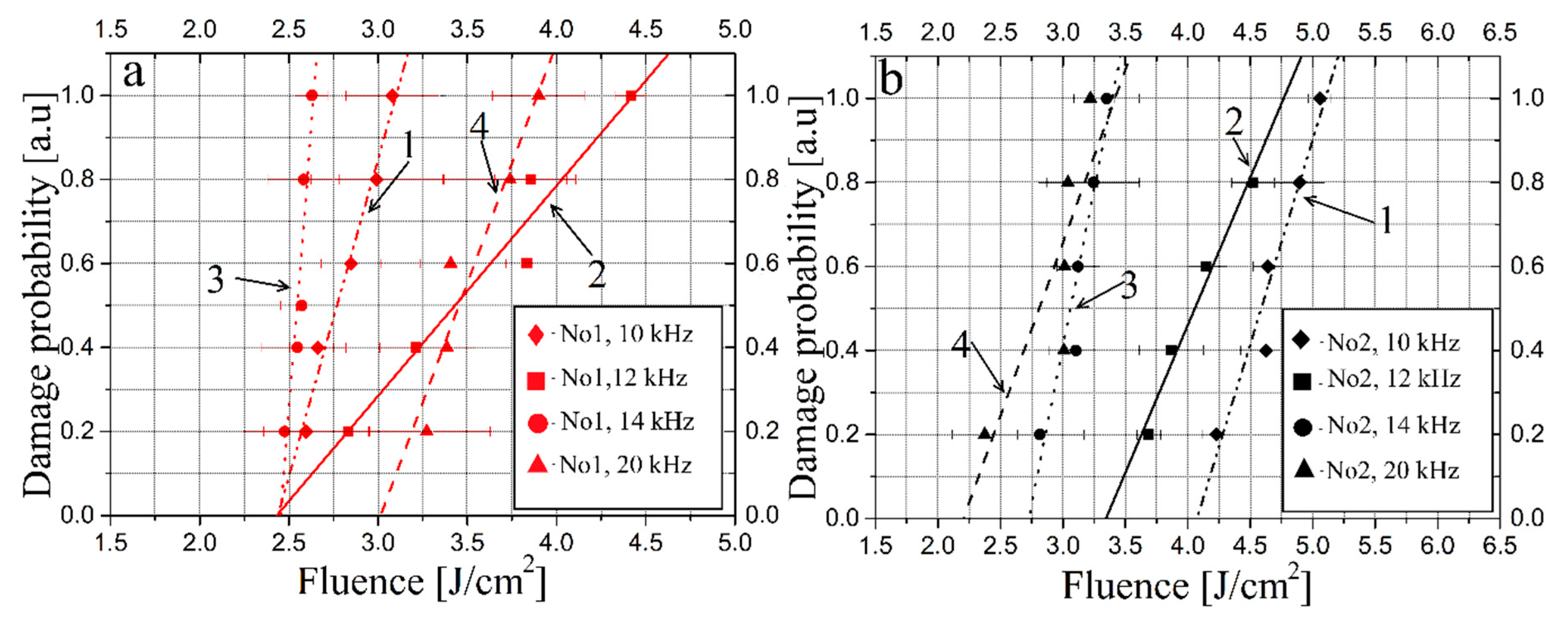
Figure 6 and
Figure 7 and
Table 2.
4. Discussion
The results of the study indicate that the damage threshold of In-doped GaSe single crystal (sample no. 2) and undoped single crystal (sample no. 1) had different dependences on the pulse repetition rate of the testing laser radiation. A more significant decrease in LIDT with an increase in the pulse repetition rate was observed in the In-doped sample, as compared to the undoped one. In terms of the fluence, the damage threshold of sample no. 1 did not actually change as the pulse repetition rate increased, but the fluence threshold decreased with an increase in the repetition rate of radiation pulses. From the results presented in
Figure 6 and
Figure 7, as well as in
Table 2, it can be seen that there was no correlation between LIDT and the intrinsic absorption of the sample. At the same time, the results obtained using digital holography methods (
Figure 3 and
Figure 4), as well as the results presented in
Figure 6 and
Figure 7 and
Table 2 indicate that the presence of volumetric defects in the GaSe:In-doped single crystal enhanced the accumulative effects compared to the undoped crystal (in which the digital holography did not detect any volumetric defects).
Thus, the obtained results made it possible to conclude that the value of GaSe damage threshold at a test radiation wavelength of 2.091 μm was influenced by accumulation effects (the damage threshold decreased as the pulse repetition rate and the pulse duration increased). The accumulation effects were more significant in the In-doped sample, since an increase in the frequency led to a more significant decrease in the damage threshold in terms of fluence and peak power, as compared to the undoped sample (for which the damage threshold in the fluence did not actually change with increasing frequency). The results obtained during the study indicate that doping with In enhanced the accumulation effect, which manifested itself in a decrease in the damage threshold with increasing frequency. The experimental results indicated that GaSe LIDT depends on both the fluence and the peak power of the test laser radiation.
The results of this work confirm the conclusions obtained in Reference [
12] on the significant influence of thermal effects on GaSe LIDT when exposed to pulsed nanosecond laser radiation, the role of which increases with the increase of pulse duration and laser pulse repetition rate.
5. Conclusions
The digital holography method revealed defects with a characteristic size of ≈300 μm in the volume of In-doped GaSe. LIDT was determined from the fluence and the peak power of GaSe (sample no. 1) and GaSe:In (sample no. 2) crystals with the parameters of the incident radiation close to the pump radiation parameters of promising dual-wavelength optical parametric oscillators (effective pump sources for THz difference frequency oscillators): wavelength was ≈2.1 μm, pulse repetition rate was 10–20 kHz, pulse duration was 15–22 ns. The damage threshold of GaSe crystal (sample no. 1) at a pulse repetition rate of 10 kHz was J/cm2 in terms of the fluence of the acting laser radiation, and MW/cm2 in terms of the peak power at a pulse repetition rate of 20 kHz J/cm2, MW/cm2. The damage threshold of GaSe:In crystal (sample no. 2) at a pulse repetition rate of 10 kHz was J/cm2 in terms of the fluence of the acting laser radiation, and MW/cm2 in terms of the peak power at a pulse repetition rate of 20 kHz J/cm2, MW/cm2.
The obtained results allow for the conclusion that the value of GaSe damage threshold at a wavelength of 2.091 μm of the incident radiation was influenced by the accumulation effects (the damage threshold decreased as the pulse repetition rate increased). The accumulation effects were more significant in the case of the In-doped sample, since a more significant decrease in the damage threshold was observed with increasing frequency in terms of the peak power and the fluence. The presence of volumetric defects reaching geometric dimensions of ≈300 μm in the GaSe:In sample seemed to enhance the accumulative effect. The results of this work confirm the conclusions obtained in [
12] on the significant influence of thermal effects on GaSe LIDT when exposed to pulsed nanosecond laser radiation, the role of which increased with the increase of pulse duration and laser pulse repetition rate. The influence of thermal effects was enhanced by the presence of volumetric defects in the samples.
The obtained results will be useful in the design and development of THz radiation oscillators based on GaSe crystals with dual-wavelength pumping by radiation in the region of ≈2.1 μm. The obtained results provide an analytical basis for determining the energy parameters of the pump radiation in order to improve energy characteristics of the THz radiation generated in GaSe and the stability of the system in the continuous mode.


 ,
, 


