Article

Effect of Compressive Strain Rate on Auxetic Foam

1
Department of Engineering, Manchester Metropolitan University, Manchester M1 5GD, UK
2
Materials and Engineering Research Institute, College of Business, Technology and Engineering, Sheffield Hallam University, Sheffield S1 1WB, UK
3
Department of Mechanical Engineering, École de Technologie Supérieure, Montréal, QC H3C 1K3, Canada
4
Research Centre, Hôpital du Sacré-Cœur de Montréal, Montréal, QC H4J 1C5, Canada
*
Author to whom correspondence should be addressed.
Appl. Sci. 2021, 11(3), 1207; https://doi.org/10.3390/app11031207
Submission received: 11 December 2020 / Revised: 15 January 2021 / Accepted: 20 January 2021 / Published: 28 January 2021
(This article belongs to the Collection Sports Equipment and Materials)

Abstract

:
Auxetic foams have previously been shown to have benefits including higher indentation resistance than their conventional counterparts, due to their negative Poisson’s ratio, making them better at resisting penetration by concentrated loads. The Poisson’s ratio and Young’s modulus of auxetic open cell foams have rarely been measured at the high compressive strain rates typical during impacts of energy absorbing material in sporting protective equipment. Auxetic closed cell foams are less common than their open cell counterparts, and only their quasi-static characteristics have been previously reported. It is, therefore, unclear how the Poisson’s ratio of auxetic foam, and associated benefits such as increased indentation resistance shown at low strain rates, would transfer to the high strain rates expected under impact. The aim of this study was to measure the effect of strain rate on the stiffness and Poisson’s ratio of auxetic and conventional foam. Auxetic open cell and closed cell polymer foams were fabricated, then compression tested to ~80% strain at applied rates up to 200 s−1, with Poisson’s ratios obtained from optical full-field strain mapping. Open cell foam quasi-static Poisson’s ratios ranged from −2.0 to 0.4, with a narrower range of −0.1 to 0.3 for closed cell foam. Poisson’s ratios of auxetic foams approximately halved in magnitude between the minimum and maximum strain rates. Open cell foam quasi-static Young’s moduli were between 0.02 and 0.09 MPa, whereas closed cell foams Young’s moduli were ~1 MPa, which is like foam in protective equipment. The Young’s moduli of the auxetic foams approximately doubled at the highest applied strain rate of 200 s−1.

1. Introduction

Sports participants often wear personal protective equipment (PPE) to reduce injury risk during collisions and falls [1]. Personal protective equipment, including back and limb protectors, traditionally use foam for cushioning and a stiff shell to spread impacts by concentrated loads [2,3,4,5,6]. These stiff shells can hinder movement and make the protective equipment bulky and uncomfortable [7,8,9,10]. Indeed, some sports participants choose not to wear PPE if it is uncomfortable [7,8,11,12,13,14,15,16].
Contemporary protective equipment can use dilatant foams [17,18,19], which are like viscoelastic foams in that they have an effective viscosity, except this viscosity increases with shear strain rate [20,21,22]. Dilatant foams can be flexible during normal use but then stiffen during impacts, so uncomfortable stiff shells [7,8,9,10] are not needed to pass certification tests [9,10,23]. Soft-shell dilatant foam back protectors intended for sports use have been certified to EN-1621-2 [24] for motorbiking, as there is no application specific standard [2,3,9,10,23,25]. Other types of sporting PPE are also designed and certified under test conditions that may not represent infield collisions and falls [26,27,28,29]. The stiffness of dilatant foams can vary exponentially when impacted and compressed at the various temperatures and speeds possible during sporting collisions and falls [9,23]. Applying such rate dependent materials to PPE means products can change in performance between certification tests and actual use, with implications for injury risk, including users overestimating how well they are protected [3,26,29]. Developing PPE that is less likely to see such changes in performance between certification tests and infield collisions and falls could, therefore, reduce the occurrence of sporting injuries.
Auxetic materials have a negative Poisson’s ratio (NPR), a characteristic that could improve PPE [4,30,31]. Poisson’s ratio is the negative of the ratio of lateral to axial strain, so auxetic materials contract laterally during axial compression and expand in tension. NPR can give benefits such as increased vibration damping [32,33] and reduced peak force under impact [34,35,36,37,38], as detailed in review papers [4,30,31]. The established benefits of NPR that are most relevant to soft-shell PPE are (i) improved equipment comfort [39,40] and (ii) increased indentation resistance [32,41,42,43,44,45]. According to Equation (1) from Hookean indentation theory, maximum indentation resistance (H, [31,42,44]) is achieved for a given Young’s modulus (E) as the magnitude of Poisson’s ratio (ν) approaches one [4]:
H     E 1 ν 2 x
whereby ‘x’ relates to indenter shape. Equation (1) has been tested for auxetic and conventional materials, including foams, using hemispheres (x = 2/3) and the flat end of a cylinder (x = 1), with NPR shown to increase indentation resistance [32,41,42,43,44,45].
For isotropic materials, Poisson’s ratio is between −1 and 0.5 [46], so indentation resistance should be highest for materials with NPR between −0.5 and −1. Replacing foam in PPE with auxetic foam with a higher magnitude of Poisson’s ratio (i.e., ideally between −0.5 and −1), which is typically between 0.1 and 0.4 for conventional foam [47,48,49], could increase indentation resistance. As such, auxetic foam could offer high indentation resistance to protect against penetrating loads, and low Young’s modulus flexibility during normal use or impacts with distributed loads, reducing the need for stiff shells. Combining auxetic and dilatant foams [50,51], or using auxetic foam in isolation, could improve the comfort of soft-shell PPE and reduce changes in performance between certification tests and actual use. The increased indentation resistance of auxetic foam could only improve soft-shell PPE if NPR is present when the material is compressed rapidly during impacts. Studies measuring NPR of foam during high strain rate compression have only tested open cell auxetic foams with relatively low magnitude NPRs (between 0 and −0.1) [36,37,52]. These studies did not control nor measure the applied strain rates, nor report that they were similar to those expected during sporting collisions and falls.
Auxetic open cell foam is the most studied auxetic foam and it has been used to show the favourable impact response associated with NPR [4,30,53]. Auxetic open cell foam is typically fabricated by a thermomechanical process involving volumetric compression of conventional open cell foam in a mould, which buckles cell ribs to impose a re-entrant cell structure, then thermal fixing (heating then cooling) of the imposed structure [54]. Compression can be equal in all axes to give isotropic auxetic foam [54] or different in each of the principal directions to impart anisotropy [55,56,57]. Typically imposed uniform (triaxial) compression reduces the foam’s volume by a factor of two to five [54,56,58], equating to 20 to 40% compressive strain in each direction. Open cell foams with compressive isotropic (same in all three axes) Poisson’s ratios as low as −0.7 have been reported [54,59,60]. Stretching foam in one direction during fabrication increases anisotropy [57] and can also increase the magnitude of Poisson’s ratio [55].
Foams used in back protectors [9,23], and closed cell foam in other PPE, like football and cricket pads [4,6], are at least ten times stiffer than open cell foam [4,56,58]. Closed cell foams used in PPE typically have Young’s moduli—the established measure of materials stiffness—close to or above 1 MPa [4,6,9,23]. Closed cell auxetic foam can be fabricated using a bespoke pressure vessel [61] or by steam processing [62,63]. Steam processing traps steam in closed cells, which condenses upon cooling to create a negative pressure differential, shrinking the foam without a mould while fixing the polymer to impart NPR [62,63]. Auxetic foams fabricated by steam processing can have similar stiffness (~1 MPa) to conventional foams in PPE [62], so they should be more suitable for this application than open cell auxetic foam.
Impact tests for certifying PPE, like back protectors (EN-1621-2 [24]), football shin guards (BS EN 13061:2009 [64]) and cricket thigh pads (BS 7928:2013 [65]), typically compress foam to densification (~80% of its thickness) in less than 5 ms [5,6,23,29,66], equating to a time-averaged engineering strain rate of ~200 s−1. During such impact tests, a drop mass is decelerated by the energy absorbing material within the product, imparting variable strain rates up to and above 200 s−1 that reduce to 0 s−1 at maximum compression. Despite the wealth of research into auxetic open cell foam, most of the previous work measured Poisson’s ratio and Young’s modulus quasi-statically (<1 s−1, [34,54,60,67,68,69,70]), or at intermediate (<10 s−1, [52]) strain rates. Poisson’s ratios of auxetic open cell foams, between 0 and −0.1, have been measured using marker tracking during impact tests at higher, but variable, strain rates of ~100 s−1 [36,37]. Closed cell auxetic foam has only been characterised quasi-statically [61,62,63]. As such, it remains unclear how the desirable Young’s modulus of auxetic closed cell foam and the NPR—that could increase indentation resistance and decrease peak force under impact—could change during sporting collisions, falls, and other impacts. It is important to understand how Young’s modulus and Poisson’s ratio of auxetic foams may change at the high strain rates expected under impact, to inform the design, and help explain the findings, of high-speed indentation and impact studies.
Here, we test auxetic open and closed cell foam at a range of compressive strain rates (0.05 to 200 s−1). We measure Young’s modulus and Poisson’s ratio at higher compression rates, and in a more controlled way, than previous work (e.g., [36,52,61,62,63,71]). A dynamic mechanical analyser applied constant rate-controlled compression to foam samples, with concurrent high-speed optical full-field strain measurement. Full-field strain measurement by digital image correlation (DIC) [70,72,73,74] gives more accurate strain measurement than tracking discrete markers. This work has implications for the application of auxetic foam to soft-shell PPE, such as potential improvements to consistency in performance between certification tests and actual use.

2. Methods

2.1. Fabrication: Open Cell Foams

Open cell polyurethane foams with two different cell structures were thermo-mechanically fabricated from 32 (z-axis) by 32 (x-axis) by 96 (y-axis) mm samples (PUR30FR, Custom Foams, as used in [35,55,75]). Fabrication conditions and, hence, imparted cell structures were selected based on previous work to give high magnitude NPR in all three orthogonal axes [58,67,76] or just one axis [55,57,62,77]. For the uniform triaxial conversions, compression to 40% engineering strain was imposed with aluminium moulds to modify cell shape in each axis (Figure 1a), giving a volumetric compression ratio (final/original volume) of five. Samples and moulds were heated in an oven (MCP Tooling Technologies LC/CD) for twenty minutes at 160 °C, then removed from the oven and cooled to room temperature (~30 min) [58]. Anisotropic foams were fabricated with 30% biaxial compression in the x- and z-axes, and extension by a factor of two in the y-axis (Figure 1b), applied using four 2 mm diameter pins passed through the foam, as in [55]. For these anisotropic samples, oven temperature was increased to 180 °C to maximise shape fixing [58]. Cell rise direction was parallel to the 32 mm z-axis in supplied open cell foam, so it was compressed during the anisotropic conversions. Three samples were converted for each condition, but one sample of anisotropic foam was discarded due to creasing.
Triaxial foam partially re-expanded following conversion, whereas anisotropic foam partially re-expanded in both compressed axes and shrank in the axis with applied tension. Partial re-expansion was intended as it is associated with increased magnitude of NPR [58,76,78], but meant the sizes of samples converted with different conditions differed slightly. Triaxial cubes with ~26 mm and anisotropic cubes with ~21 mm sides were cut from cuboidal samples a week after fabrication with a utility knife (Stanley), with cuts made perpendicular to sample length only (y-axis, Figure 1) to ensure straight, undamaged sides. Unconverted cubes (~25 mm sided) of similar size to the triaxial cubes were also cut for comparative testing.

2.2. Fabrication: Closed Cell Foams

Closed cell auxetic foam was fabricated by steam processing, based on previous work [62,63]. Three samples of low-density polyethylene closed cell foam, with similar Young’s modulus and density to foam used in sporting PPE [6] (Plastazote LD-60, Algeos, 10 × 20 × 100 mm), were placed (partially submerged) in a cylindrical container (diameter 75 mm, height 150 mm) three-quarters filled with water (at 20 °C). The container was then sealed with aluminium foil and placed in an oven (MCP Tooling Technologies LC/CD) at 105 °C for five hours to steam the samples. After steaming, the samples were removed from the container and cooled in air on a drying rack, imparting triaxial compression as the trapped steam condensed. Following conversion, the foam samples had a concave cross-sectional profile (~1.5 mm deep, Figure 1), as expected [62,63]. A 15 × 15 × 8 mm quasi-cuboid (Figure 1c) with a concave cross-sectional profile (Figure 1d), but straight sides parallel to the 15 mm z dimension and 8 mm x dimension (see Figure 2a), was cut from the centre of samples for compression testing. Three samples of unconverted foam (20 × 20 × 10 mm), with similar mass and aspect ratio to auxetic samples were also cut for testing. As with the open cell foam, there were slight size differences between sample dimensions after fabrication, so aspect ratios and mass were kept constant between conventional and auxetic test samples. Sample storage and testing was in air-conditioned rooms and laboratories (20 °C, relative humidity between 10 and 30%).

2.3. Cell Structures

Images showing cell structures were collected to demonstrate cell morphology and then explain measured mechanical properties based on established theory [47]. Microscopic images (Leica LD-60) of 1 to 2 mm thick (~1 cell) slices of the open cell foam were collected to compare cell shapes. Micro-computed tomography of ~4 × 5 × 20 mm samples of closed cell foam was also undertaken, with volume renderings used to compare cell shapes (SkyScan 1172; 180° rotation, image acquisition every 0.7°, resolution < 5 µm, volume depth 300 to 500 µm).

2.4. Compression Testing

Compression testing was parallel to the long cell axis of anisotropic (y-axis), and unconverted (z-axis) open cell foams, as these were the directions where the highest magnitudes of Poisson’s ratio were expected [47,57,62]. The triaxial open cell foam was compressed in its z-axis. Samples were compressed by 12 mm (Bose ElectroForce 3200, 250 N load cell Figure 2), imparting 45 to 80% compression for respective 25 to 15 mm thick samples, with foam densification expected at ~80% compression [47,49,79]. Applied compression rates were 0.1, 1, 10, 50, 250, 1000, and 3250 mm/s, giving applied strain rates between ~0.05 and 200 s−1. All samples were tested once at the lowest rate of 0.1 mm/s, then the sample from each group type with the median stress at 10% compression was selected for testing at the higher rates. The stiffer of the two anisotropic open cell foam samples was selected. The five selected samples were tested once at each of the higher rates, with at least 15 min between tests. For compression rates over 100 s−1, the total displacement was as low as 40% of the intended displacement (of 12 mm) due to device safety features. Data logging frequency was 30 Hz for compression rates of 0.1 mm/s, 60 Hz for 1 mm/s, 1 kHz for 10 mm/s, and 5 kHz for 50 mm/s and above.
Surfaces were prepared with a speckle pattern (Halfords Matt Black or White Primer) to allow 2D DIC (Figure 2). Tests were filmed (Proton, FASTCAM_SA3, 60K & Nikon, Nikkor 35 mm f/2D lens) at a frame rate that matched the sample rate of the test device, and with the camera’s image plane parallel to the front face of the sample. Video footage was analysed (GOM Correlate, free 2D DIC software) to obtain lateral and axial engineering strains and strain rates in a target area (~5 mm high, 15 to 25 mm wide) in the centre of the samples (Figure 2a), avoiding the regions affected by contact with the compression plates [58].
Engineering stress vs. strain was calculated from test device force vs. displacement data, and sample dimensions. Values for Young’s modulus (Ez for unconverted and triaxial foams, and Ey anisotropic foam) and Poisson’s ratio (νzx or νyx as above) were obtained from the gradients of straight lines fitted to respective stress or lateral strain vs. axial strain between 0 and 2% compression, within the quasi-linear region for all foams.

3. Results

A summary of all data described below is in Supplementary Table S1.
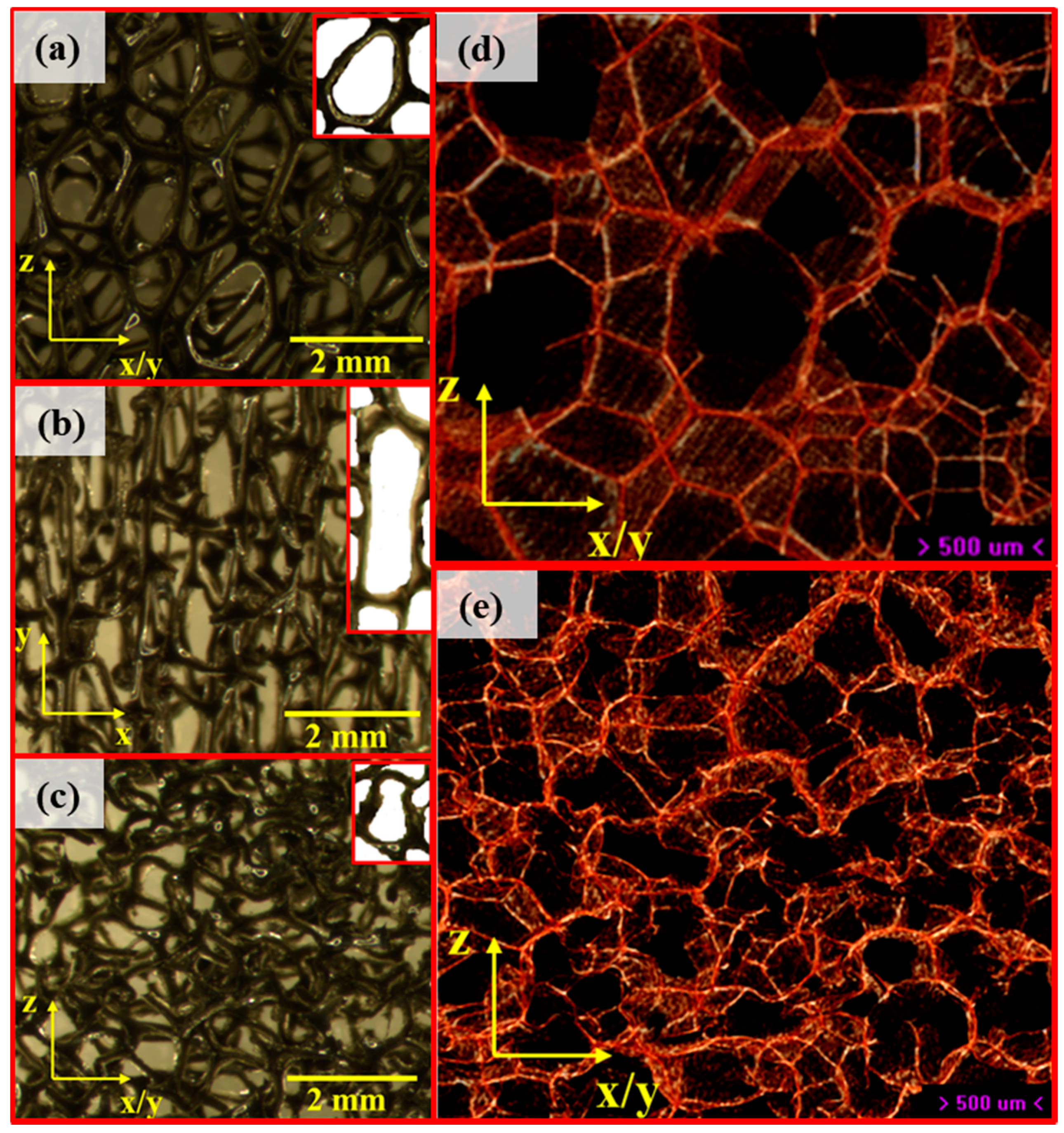
The unconverted (UC) open cell foam had hexagonal shaped cells, elongated in the cell rise direction (z-axis, Figure 3a), as expected [47,58,71]. The anisotropic open cell foam had elongated cells in the stretched directions (y-axis, Figure 3b), and slightly inward angled, or re-entrant ribs, in the compressed x and z directions. The triaxially compressed open cell foam had re-entrant like cells (Figure 3c), as expected [47,58,71]. Also as expected [62,71], the unconverted closed cell foam had hexagonal cells with no visible cell rise direction (Figure 3d), and the triaxially converted closed cell foam had re-entrant like, kinked cell walls (Figure 3e) [62,71].

3.1. Poisson’s Ratio

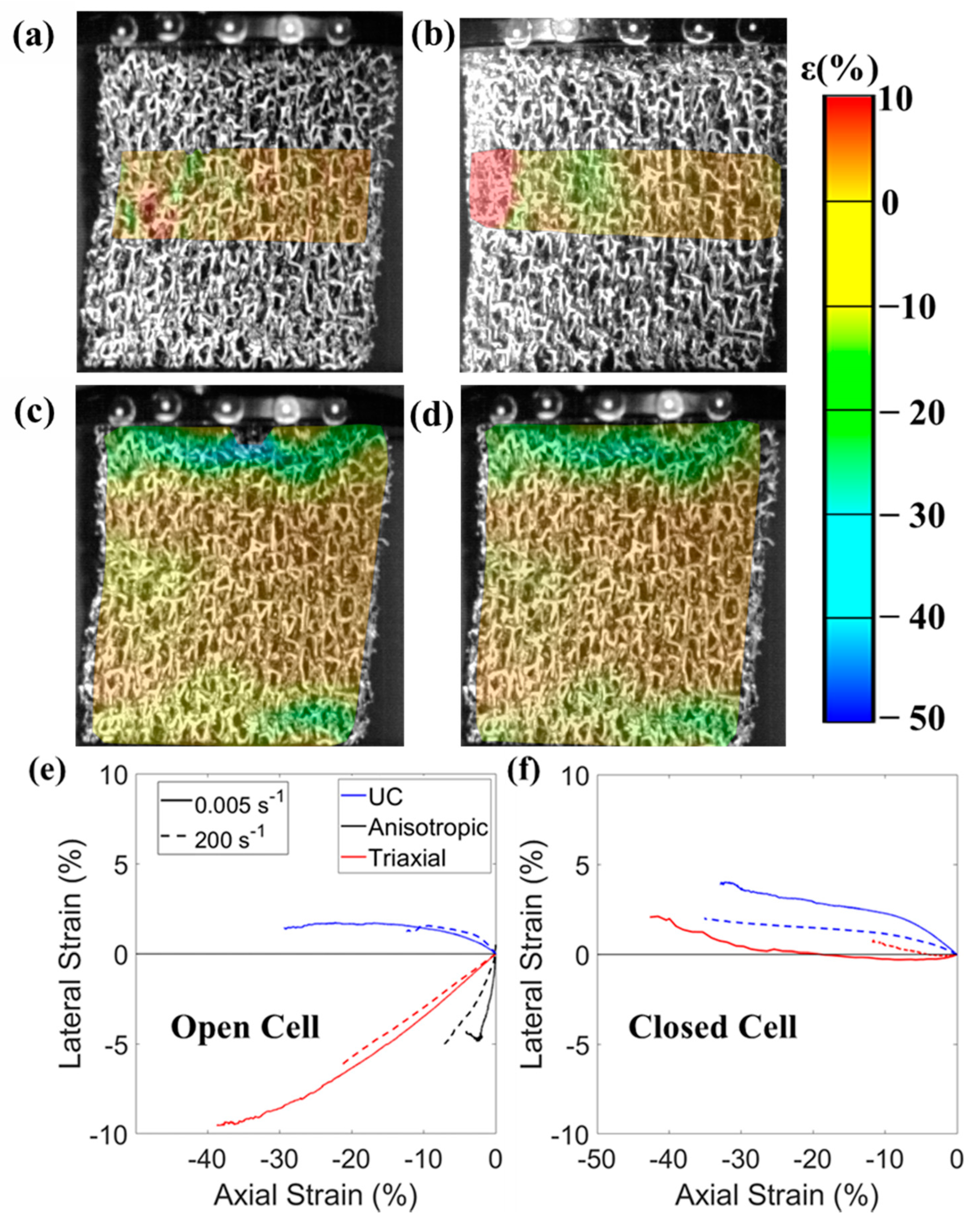
Auxetic foams exhibited NPR up to ~2% compression for all applied strain rates (Figure 4 and Figure 5, Supplementary Figure S1). Lateral strain mapping (x-axis) at 2% compression parallel to the y-axis shows the anisotropic open cell foam in predominantly lateral contraction (Figure 4a,b) at the lowest and highest applied strain rates. Axial strain was higher (~50%) within ~2 mm of the compression plates than in the central region of the sample, where it was close to the applied value of 2% (Figure 4c,d); attributed to contact effects [58]. Measured maximum strain rates in the central region of the samples were, then, lower (80 s−1) than imposed values (200 s−1, Supplementary Figure S1). Maximum measured strains were also lower (10 to 60%, Figure 4e,f and Supplementary Figure S1) than imposed values (40 to 80%), partly due to lower stiffness in the contact regions, but also due to a safety feature in the test device limiting the applied strain at higher strain rates.
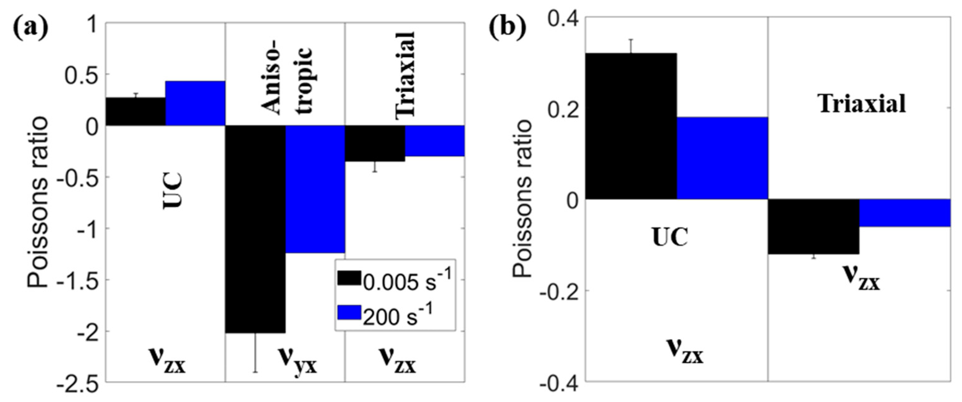
The magnitude of Poisson’s ratio (Figure 5) increased with applied strain rates (of 0.005 to 200 s−1) for unconverted open cell foam (νzx = 0.27 ± 0.04 to 0.44) and decreased for all other foams (open cell anisotropic, νyx = −2.02 ± 0.38 to −1.24; open cell triaxial, νzx = −0.35 ± 0.03 to −0.30; closed cell unconverted, νzx = 0.32 ± 0.03 to 0.18 and closed cell triaxial, νzx = −0.12 ± 0.01 to −0.06). These differences in Poisson’s ratios with applied strain rates were similar across the lateral vs. axial strain range (Figure 4e,f), so the differences in Poisson’s ratio reported in Figure 5 are a good representation of the effect of strain rate. Standard deviations indicate differences between samples at the lowest strain rate were also relatively small (maximum standard error = 20% of mean Poisson’s ratio, Figure 5).

3.2. Young’s Moduli

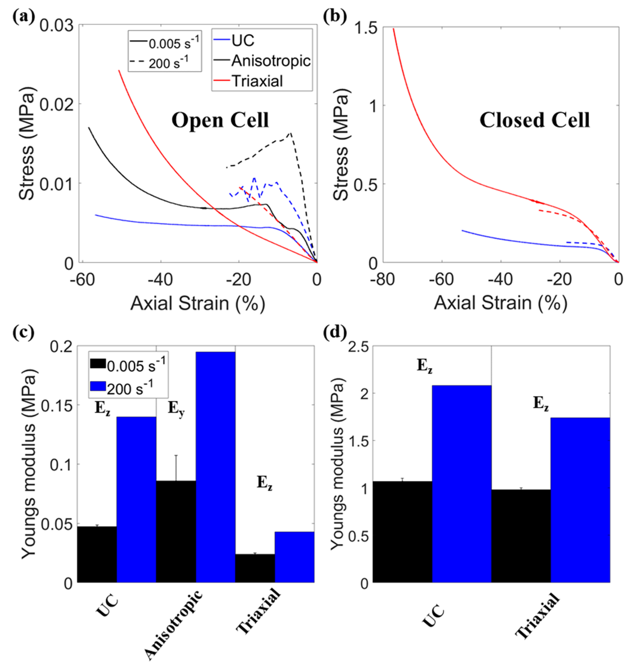
Increasing the applied strain rate from 0.005 to 200 s−1 approximately doubled Young’s modulus in most cases (Figure 6), but almost tripled the unconverted open cell foam’s Young’s modulus (Figure 6c), with values reported in supplementary Table S1. Both closed cell foams exhibited quasi-static Young’s moduli of ~1 MPa (Figure 6d), as expected [62]. Increases in Young’s modulus with applied strain rate were similar across the stress vs. strain (Figure 6a,b) and Young’s modulus vs. strain rate relationships (Supplementary Figure S2). Standard deviations indicate differences between samples at the lowest strain rate were also relatively small (maximum standard error = 10% of mean Young’s modulus, Figure 6c,d).

4. Discussion

Negative Poisson’s ratio of auxetic foam was observed with full-field strain measurement at higher applied strain rates of up to 200 s−1 than in previous work [58,68,69,70]. NPR was present at the highest strain rates, in agreement with previous tests at imposed rates of 10 s−1 [52] and impacts imparting variable strain rates of ~100 s−1 [36], but approximately halved at the highest strain rate (Figure 5). Established benefits to quasi-static indentation resistance from NPR [32,41,42,43,44,45] may, then, apply during impacts of auxetic foams, but should be confirmed in further work. Measured strain rates (80 s−1) were lower than the maximum applied value of 200 s−1, due to higher compression close to the plates (Figure 4c,d) than in the central region where Poisson’s ratio was measured (Figure 4a,b). Obtained NPRs here were of higher magnitude (ν −0.1 to −2 Figure 5) than reported in previous studies measuring NPR quasi-statically and under impact (ν > −0.1 [36,52]), where strain rates were neither constant nor measured.
The anisotropic open cell foam exhibited high magnitude NPR below −1 (Figure 5a). Previous work on high aspect ratio (i.e., highly anisotropic) cell structures in foams also showed high anisotropy in mechanical properties; which typically have high Young’s moduli and high magnitudes of Poisson’s ratios parallel to the elongated cell axis [55,57,62]. Figure 3b shows the elongated cells along the y-axis (the stretched direction during conversion). Gibson and Ashby’s flexure model [47], considering flexing of the slightly re-entrant long cell ribs (Figure 3b), would give higher strains along the perpendicular (lateral) x- or z-axes during compression or tension in the long cell y-axis, and hence high magnitude NPR.
Steam processed auxetic closed cell foam had quasi-static Poisson’s ratio of −0.12 (Figure 5b) up to 2% compression. The quasi-static Young’s modulus (~1 MPa, Figure 6d) of this auxetic closed cell foam was at the lower end of the reported range for foam in snow-sports back protectors (1 to 10 MPa [9,23]), football shin guards [6,66] and cricket thigh pads [5], to name a few. Young’s modulus of the auxetic closed cell foam approximately doubled while NPR halved between minimum (0.005 s−1) and maximum strain rates (200 s−1, Figure 6d). This doubling of Young’s modulus as strain rate increased by 40,000 times is lower than the increase by a factor of five with increased strain rate of only 50 times reported for dilatant foam in soft-shell back protectors [9]. The linear relationship between Young’s modulus and strain rate (Supplementary Figure S2) suggests the closed cell foams tested here were viscoelastic, rather than dilatant [20]. Recent work with the parent foam used here has produced higher magnitude anisotropic NPRs, approaching −1, in larger sheets of auxetic closed cell foam [62]. Further work could test whether such high magnitude NPR auxetic closed cell foam in isolation, or in combination with dilatant foam, could pass certification tests and ultimately enhance protection during sporting collisions and falls.
The sample sizes of 13 to 20 mm for closed cell and 20 to 25 mm for open cell foam, due to the various conversion methods, caused differences in applied strains (45 to 80%, Figure 4e,f) and strain rates (120 to 250 s−1, Supplementary Figure S1) during compression testing. Sample sizes were otherwise accounted for in stress and strain calculations. The relative increase in strain rate (lowest to highest) was caused by differences in applied compression rate and so was the same between samples, despite the different sizes. We have demonstrated that NPR was maintained at the high strain rates expected under impact using 2D DIC, but NPR approximately halved in magnitude at the highest compression rates (Figure 4 and Figure 5). Further work could use 3D DIC to confirm the Poisson’s ratios measured here. Finite element modelling or digital volume correlation following high-speed micro-computed tomography [80] could also be applied to estimate or measure strain through the bulk of the foam. Impact testing auxetic closed cell foam, with similar stiffness (1 MPa, Figure 6d) to foam in sporting PPE [5,6,23,29], could show whether the established benefits of NPR to quasi-static indentation resistance (Equation (1) [32,41,42,43,44,45]) and peak force under impact [34,35,36,37,38], inferred but not tested here, could improve sporting PPE. Further high-speed impact [81] and indentation testing could assess theoretical improvements by NPR. As the magnitude of NPR can decrease between quasi-static and high strain rate tests, high-speed indentation studies should focus on testing auxetic foam that has high magnitude quasi-static NPR (e.g., [42,54,59,60,61,63,71]).

5. Conclusions

Poisson’s ratios and Young’s moduli were measured at low (0.005 s−1) and high (200 s−1) compressive strain rates, comparable to those imparted during impact tests for certifying sporting personal protective equipment. Negative Poisson’s ratios at the highest strain rate were about half those measured quasi-statically, for both open and closed cell auxetic foams. Young’s moduli typically doubled between the lowest and highest applied strain rates. This work indicates that NPR, and by extension NPR’s known benefits to indentation resistance, are possible for auxetic foams during sporting impacts.

Supplementary Materials

The following are available online at https://www.mdpi.com/2076-3417/11/3/1207/s1, Figure S1: Poisson’s ratio vs. strain rate, Figure S2: Young’s modulus vs. strain rate, Table S1: Summary data, Video S1: DIC Video (Anisotropic foam).

Author Contributions

O.D. fabricated the foams and tested them with N.B., with feedback from all authors. O.D., T.A. and N.B. wrote the paper, Y.P., E.W. and A.A. provided feedback. All authors have read and agreed to the published version of the manuscript.

Funding

This research received funding from the International Sports Engineering Association—via. their engaging sports engineering grant (https://www.sportsengineering.org/engaging-sports-engineering-grants/), from Manchester Metropolitan University’s Strategic Opportunities Fund, and Sheffield Hallam University’s Creating Knowledge Investment Platform.

Institutional Review Board Statement

Not Applicable.

Informed Consent Statement

Not Applicable.

Data Availability Statement

Available from first author upon reasonable request.

Acknowledgments

The authors would like to thank the International Sports Engineering Association for providing funding to carry out the testing through their engaging sports engineers grant.

Conflicts of Interest

The authors declare no conflict of interest.

References

  1. Payne, T.; Mitchell, S.; Halkon, B.; Bibb, R. A systematic approach to the characterisation of human impact injury scenarios in sport. BMJ Open Sport Exerc. Med. 2016, 2, e000017. [Google Scholar] [CrossRef] [PubMed] [Green Version]
  2. Michel, F.I.; Schmitt, K.U.; Liechti, B.; Stämpfli, R.; Brühwiler, P. Functionality of back protectors in snow sports concerning safety requirements. Procedia Eng. 2010, 2, 2869–2874. [Google Scholar] [CrossRef]
  3. Schmitt, K.-U.; Liechti, B.; Michel, F.I.; Stämpfli, R.; Brühwiler, P.A. Are current back protectors suitable to prevent spinal injury in recreational snowboarders? Br. J. Sports Med. 2010, 44, 822–826. [Google Scholar] [CrossRef] [PubMed]
  4. Duncan, O.; Shepherd, T.; Moroney, C.; Foster, L.; Venkatraman, P.D.; Winwood, K.; Allen, T.; Alderson, A. Review of auxetic materials for sports applications: Expanding options in comfort and protection. Appl. Sci. 2018, 8, 941. [Google Scholar] [CrossRef] [Green Version]
  5. Hrysomallis, C.; Morrison, W.; He, J. Assessing the shock absorption of thigh pads. J. Sci. Med. 1999, 2, 49. [Google Scholar] [CrossRef]
  6. Ankrah, S.; Mills, N.J. Performance of football shin guards for direct stud impacts. Sports Eng. 2003, 6, 207–219. [Google Scholar] [CrossRef]
  7. Wardiningsih, W.; Troynikov, O.; Nawaz, N.; Watson, C. Influence of wearing impact protective garment on thermophysiological comfort of the wearer. Procedia Eng. 2014, 72, 551–556. [Google Scholar] [CrossRef] [Green Version]
  8. Webster, J. The Perception of Comfort and Fit of Personal Protective Equipment in Sport. Ph.D. Thesis, Loughborough University, Loughborough, UK, 2010. [Google Scholar]
  9. Nicotra, M.; Moncalero, M.; Messori, M.; Fabbri, E.; Fiorini, M.; Colonna, M. Thermo-mechanical and impact properties of polymeric foams used for snow sports protective equipment. Procedia Eng. 2014, 72, 678–683. [Google Scholar] [CrossRef] [Green Version]
  10. Dotti, F.; Ferri, A.; Moncalero, M.; Colonna, M. Thermo-physiological comfort of soft-shell back protectors under controlled environmental conditions. Appl. Ergon. 2016, 56, 144–152. [Google Scholar] [CrossRef]
  11. Finch, C.F.; McIntosh, A.S.; McCrory, P. What do under 15 year old schoolboy rugby union players think about protective headgear? Br. J. Sports Med. 2001, 35, 89–94. [Google Scholar] [CrossRef] [Green Version]
  12. Quinn, E.M.; Bradley, C.P. Injury prevention in camogie: Current trends in the use of protective equipment. Eur. J. Sport Sci. 2012, 12, 185–192. [Google Scholar] [CrossRef]
  13. Webster, J.M.; Roberts, J. Incorporating subjective end-user perceptions in the design process: A study of leg guard comfort in cricket. Proc. Inst. Mech. Eng. Part P J. Sport. Eng. Technol. 2009, 223, 49–62. [Google Scholar] [CrossRef] [Green Version]
  14. Webster, J.M.; Roberts, J.R. Comfort of cricket leg guards: A study of strap contact pressure. Procedia Eng. 2010, 2, 3385–3390. [Google Scholar] [CrossRef] [Green Version]
  15. Hughes, A.; Carré, P.M.; Driscoll, H. Perceptions and Attitudes Towards Shoulder Padding and Shoulder Injury in Rugby Union. medRxiv 2020, 1–12. [Google Scholar] [CrossRef]
  16. Brisbine, B.R.; Steele, J.R.; Phillips, E.J.; McGhee, D.E. Use and perception of breast protective equipment by female contact football players. J. Sci. Med. Sport. 2020, 23, 820–825. [Google Scholar] [CrossRef]
  17. Palmer, R.M.; Green, P.C. Energy Absorbing Material. US Patent US 7381460B2, 3 June 2008. [Google Scholar]
  18. Plant, D.J. Energy Absorbing System. US Patent US 2012/0021167A1, 26 January 2012. [Google Scholar]
  19. Wyner, D.M.; Fox, R.B.; Cafaro, T.; Thorn, S.; Newsham, A.; Foster, D. Flexible Cushioning Pads, Items Incorporating Such Pads, and Methods of Making and Using. US Patent US 9,770,642B2, 26 September 2017. [Google Scholar]
  20. Cossa, K.N. Basic concepts on rheology and application of shear-thickening fluids in protective gear. SN Appl. Sci. 2019, 1, 1284. [Google Scholar] [CrossRef] [Green Version]
  21. Bhagavathula, K.B.; Azar, A.; Ouellet, S.; Satapathy, S.; Dennison, C.R.; Hogan, J.D. High Rate Compressive Behaviour of a Dilatant Polymeric Foam. J. Dyn. Behav. Mater. 2018, 4, 573–585. [Google Scholar] [CrossRef]
  22. Kaewpradit, P.; Kongchoo, A.; Chonlathan, P.; Lehman, N.; Kalkornsurapranee, E. Impact Absorbing Kneepad Prepared from Natural Rubber. In Proceedings of the IOP Conference Series: Materials Science and Engineering, Bangkok, Thailand, 16–18 December 2019; Volume 773, p. 012063. [Google Scholar]
  23. Signetti, S.; Nicotra, M.; Colonna, M.; Pugno, N.M. Modeling and simulation of the impact behavior of soft polymeric-foam-based back protectors for winter sports. J. Sci. Med. Sport 2019, 22, S65–S70. [Google Scholar] [CrossRef]
  24. Standardization, E.C. for. EN 1621-2 2003 Motorradfahrer Schutzkleidung Teil 2 Rückenprotektoren. 2003. Available online: https://shop.bsigroup.com/ProductDetail/?pid=000000000030109684 (accessed on 26 January 2021).
  25. Wei, W.; Evin, M.; Bailly, N.; Llari, M.; Laporte, J.D.; Arnoux, P.J. Spinal injury analysis for typical snowboarding backward falls. Scand. J. Med. Sci. Sport 2019, 29, 450–459. [Google Scholar] [CrossRef]
  26. Michel, F.I.; Schmitt, K.U.; Greenwald, R.M.; Russell, K.; Simpson, F.I.; Schulz, D.; Langran, M. White Paper: Functionality and efficacy of wrist protectors in snowboarding-towards a harmonized international standard. Sports Eng. 2013, 16, 197–210. [Google Scholar] [CrossRef] [Green Version]
  27. Mcintosh, A.S. Biomechanical considerations in the design of equipment to prevent sports injury. Proc. Inst. Mech. Eng. Part P J. Sport. Eng. Technol. 2011, 226, 193–199. [Google Scholar] [CrossRef]
  28. Payne, T.; Mitchell, S.; Halkon, B.; Bibb, R.; Waters, M. Development of a synthetic human thigh impact surrogate for sports personal protective equipment testing. Proc. Inst. Mech. Eng. Part P J. Sport. Eng. Technol. 2016, 230, 5–16. [Google Scholar] [CrossRef] [Green Version]
  29. Whyte, T.; Stuart, C.A.; Mallory, A.; Ghajari, M.; Plant, D.J.; Siegmund, G.P.; Cripton, P.A. A Review of Impact Testing Methods for Headgear in Sports: Considerations for Improved Prevention of Head Injury Through Research and Standards. J. Biomech. Eng. 2019, 141, 070803. [Google Scholar] [CrossRef] [PubMed]
  30. Novak, N.; Vesenjak, M.; Ren, Z. Auxetic cellular materials—A review. Stroj. Vestnik/J. Mech. Eng. 2016, 62, 485–493. [Google Scholar] [CrossRef] [Green Version]
  31. Evans, K.E.; Alderson, A. Auxetic materials: Functional materials and structures from lateral thinking! Adv. Mater. 2000, 12, 617–628. [Google Scholar] [CrossRef]
  32. Scarpa, F.; Giacomin, J.; Zhang, Y.; Pastorino, P. Mechanical performance of auxetic polyurethane foam for antivibration glove applications. Cell. Polym. 2005, 24, 253–268. [Google Scholar] [CrossRef] [Green Version]
  33. Scarpa, F.; Ciffo, L.G.; Yates, J.R. Dynamic properties of high structural integrity auxetic open cell foam. Smart Mater. Struct. 2003, 13, 49–56. [Google Scholar] [CrossRef]
  34. Duncan, O.; Foster, L.; Senior, T.; Alderson, A.; Allen, T. Quasi-static characterisation and impact testing of auxetic foam for sports safety applications. Smart Mater. Struct. 2016, 25, 054014. [Google Scholar] [CrossRef]
  35. Foster, L.; Peketi, P.; Allen, T.; Senior, T.; Duncan, O.; Alderson, A. Application of Auxetic Foam in Sports Helmets. Appl. Sci. 2018, 8, 354. [Google Scholar] [CrossRef] [Green Version]
  36. Allen, T.; Shepherd, J.; Hewage, T.A.M.; Senior, T.; Foster, L.; Alderson, A. Low-kinetic energy impact response of auxetic and conventional open-cell polyurethane foams. Phys. Status Solidi Basic Res. 2015, 252, 1631–1639. [Google Scholar] [CrossRef]
  37. Ge, C. A comparative study between felted and triaxial compressed polymer foams on cushion performance. J. Cell. Plast. 2013, 49, 521–533. [Google Scholar] [CrossRef]
  38. Lisiecki, J.; Błazejewicz, T.; Kłysz, S.; Gmurczyk, G.; Reymer, P.; Mikułowski, G. Tests of polyurethane foams with negative Poisson’s ratio. Phys. Status Solidi Basic Res. 2013, 250, 1988–1995. [Google Scholar] [CrossRef]
  39. Evans, K.E. The design of doubly curved sandwich panels with honeycomb cores. Compos. Struct. 1991, 17, 95–111. [Google Scholar] [CrossRef]
  40. Cross, T.M.; Hoffer, K.W.; Jones, D.P.; Kirschner, P.B.; Meschter, J.C. Auxetic Structures and Footwear with Soles Having Auxetic Structures. U.S. Patent No. 9,402,439, 19 March 2015. [Google Scholar]
  41. Alderson, K.L.; Fitzgerald, A.; Evans, K.E. The strain dependent indentation resilience of auxetic microporous polyethylene. J. Mater. Sci. 2000, 35, 4039–4047. [Google Scholar] [CrossRef]
  42. Chan, N.; Evans, K.E. Indentation resilience of conventional and auxetic foams. J. Cell. Plast. 1998, 34, 231–260. [Google Scholar] [CrossRef]
  43. Lakes, R.S.; Elms, K. Indentability of conventional and negative Poisson’s ratio foams. J. Compos. Mater. 1993, 27, 1193–1202. [Google Scholar] [CrossRef] [Green Version]
  44. Alderson, K.L.; Pickles, A.P.; Neale, P.J.; Evans, K.E. Auxetic polyethylene: The effect of a negative Poisson’s ratio on hardness. Acta Metall. Mater. 1994, 42, 2261–2266. [Google Scholar] [CrossRef]
  45. Argatov, I.I.; Sabina, F.J. Small-scale indentation of an elastic coated half-space: The effect of compliant substrate. Int. J. Eng. Sci. 2016, 104, 87–96. [Google Scholar] [CrossRef]
  46. Timoshenko, S.P.; Goodier, J.N. Theory of Elasticity, 3rd ed.; McGraw-Hill: New York, NY, USA, 1970. [Google Scholar]
  47. Gibson, L.J.; Ashby, M.F. Cellular Solids: Structure and Properties; Press Syndicate of the University of Cambridge: Cambridge, UK, 1997; pp. 67, 176–183, 259–264, 286, 301. 498p. [Google Scholar]
  48. Mills, N.J.; Fitzgerald, C.; Gilchrist, A.; Verdejo, R. Polymer foams for personal protection: Cushions, shoes and helmets. Compos. Sci. Technol. 2003, 63, 2389–2400. [Google Scholar] [CrossRef]
  49. Mills, N.J.; Zhu, H.X. The high strain compression of closed-cell polymer foams. J. Mech. Phys. Solids 1999, 47, 669–695. [Google Scholar] [CrossRef]
  50. Plant, D.; Leevers, P. Injection moldable rate stiffening re-entrant cell arrays for wearable impact protection. Polym. Eng. Sci. 2020, 60, 1546–1555. [Google Scholar] [CrossRef]
  51. Nakonieczna, P.; Wierzbicki, Ł.; Śladowska, B.; Leonowicz, M.; Lisiecki, J. Composites with impact absorption ability based on shear thickening fluids and auxetic foams. Compos. Theory Pract. 2017, 2, 67–72. [Google Scholar]
  52. Pastorino, P.; Scarpa, F.; Patsias, S.; Yates, J.R.; Haake, S.J.; Ruzzene, M. Strain rate dependence of stiffness and Poisson’s ratio of auxetic open cell PU foams. Phys. Status Solidi Basic Res. 2007, 244, 955–965. [Google Scholar] [CrossRef]
  53. Critchley, R.; Corni, I.; Wharton, J.A.; Walsh, F.C.; Wood, R.J.K.; Stokes, K.R. A review of the manufacture, mechanical properties and potential applications of auxetic foams. Phys. Status Solidi Basic Res. 2013, 250, 1963–1982. [Google Scholar] [CrossRef]
  54. Lakes, R.S. Foam Structures with a Negative Poisson’s Ratio. Science 1987, 235, 1038–1040. [Google Scholar] [CrossRef] [PubMed]
  55. Duncan, O.; Allen, T.; Foster, L.; Senior, T.; Alderson, A. Fabrication, characterisation and modelling of uniform and gradient auxetic foam sheets. Acta Mater. 2017, 126, 426–437. [Google Scholar] [CrossRef]
  56. Chan, N.; Evans, K.E. Fabrication methods for auxetic foams. J. Mater. Sci. 1997, 32, 5945–5953. [Google Scholar] [CrossRef]
  57. Alderson, A.; Davies, P.J.; Alderson, K.I.M.L.; Smart, G.M. The Effects of Processing on the Topology and Mechanical Properties of Negative Poisson’s Ratio Foams. In Proceedings of the IMECE2005 2005 ASME International Mechanical Engineering Congress and Exposition IMECE200, Orlando, FL, USA, 5–11 November 2005; pp. 1–8. [Google Scholar]
  58. Duncan, O.; Clegg, F.; Essa, A.; Bell, A.M.T.; Foster, L.; Allen, T.; Alderson, A. Effects of Heat Exposure and Volumetric Compression on Poisson’s Ratios, Young’s Moduli, and Polymeric Composition During Thermo-Mechanical Conversion of Auxetic Open Cell Polyurethane Foam. Phys. Status Solidi 2019, 256, 1800393. [Google Scholar] [CrossRef] [Green Version]
  59. Choi, J.B.; Lakes, R.S. Nonlinear Analysis of the Poisson’s Ratio of Negative Poisson’s Ratio Foams. J. Compos. Mater. 1994, 29, 113–128. [Google Scholar] [CrossRef]
  60. Chan, N.; Evans, K.E. The mechanical properties of conventional and auxetic foams. Part I: Compression and tension. J. Cell. Plast. 1999, 35, 130–165. [Google Scholar]
  61. Martz, E.O.; Lee, T.; Lakes, R.S.; Goel, V.K.; Park, J.B. Re-entrant transformation methods in closed cell foams. Cell. Polym. 1996, 15, 229–249. [Google Scholar]
  62. Duncan, O.; Allen, T.; Birch, A.; Foster, L.; Hart, J.; Alderson, A. Effect of steam conversion on the cellular structure, Young’s modulus and negative Poisson’s ratio of closed cell foam. Smart Mater. Struct. 2020, 30, 015031. [Google Scholar] [CrossRef]
  63. Fan, D.; Li, M.; Qiu, J.; Xing, H.; Jiang, Z.; Tang, T. Novel Method for Preparing Auxetic Foam from Closed-Cell Polymer Foam Based on the Steam Penetration and Condensation Process. ACS Appl. Mater. Interfaces. 2018, 10, 22669–22677. [Google Scholar] [CrossRef] [PubMed]
  64. European Committee for Standardization. BS EN 13061:2009 Protective Clothing—Shin Guards for Association Football Players—Requirements and Test Methods. BS EN: 13061:2009. 2009. Available online: https://www.en-standard.eu/bs-en-13061-2009-protective-clothing.-shin-guards-for-association-football-players.-requirements-and-test-methods/ (accessed on 26 January 2021).
  65. European Committee for Standardization. BS 6183-3:2000-Protective Equipment for Cricketers. 2000. Available online: https://shop.bsigroup.com/ProductDetail/?pid=000000000019995423 (accessed on 26 January 2021).
  66. Ankrah, S.; Mills, N.J. Analysis of ankle protection in Association football. Sports Eng. 2004, 7, 41–52. [Google Scholar] [CrossRef]
  67. Critchley, R.; Smy, V.; Corni, I.; Wharton, J.A.; Walsh, F.C.; Robert, J.K.; Wood, R.J.; Stokes, K.R. Experimental and computation assessment of thermomechanical effects during auxetic foam fabrication. Sci. Rep. 2020, 10, 1–14. [Google Scholar] [CrossRef]
  68. Allen, T.; Hewage, T.; Newton-Mann, C.; Wang, W.; Duncan, O.; Alderson, A. Fabrication of Auxetic Foam Sheets for Sports Applications. Phys. Status Solidi Basic Res. 2017, 254, 1700596. [Google Scholar] [CrossRef] [Green Version]
  69. McDonald, S.A.; Dedreuil-Monet, G.; Yao, Y.T.; Alderson, A.; Withers, P.J. In situ 3D X-ray microtomography study comparing auxetic and non-auxetic polymeric foams under tension. Phys. Status Solidi Basic Res. 2011, 248, 45–51. [Google Scholar] [CrossRef]
  70. Pierron, F. Identification of Poisson’s ratios of standard and auxetic low-density polymeric foams from full-field measurements. J. Strain Anal. Eng. Des. 2010, 45, 233–253. [Google Scholar] [CrossRef]
  71. Duncan, O.; Alderson, A.; Allen, T. Fabrication, characterisation and analytical modelling of gradient auxetic closed cell foams. Smart Mater. Struct. 2021. [Google Scholar] [CrossRef]
  72. Lane, B.; Sherratt, P.; Hu, X.; Harland, A. Measurement of strain and strain rate during the impact of tennis ball cores. Appl. Sci. 2018, 8, 371. [Google Scholar] [CrossRef] [Green Version]
  73. Šleichrt, J.; Fíla, T.; Koudelka, P.; Adorna, M.; Falta, J.; Zlámal, P.; Glinz, J.; Neuhäuserová, M.; Doktor, T.; Mauko, A.; et al. Dynamic penetration of cellular solids: Experimental investigation using Hopkinson bar and computed tomography. Mater. Sci. Eng. A 2021, 800, 140096. [Google Scholar] [CrossRef]
  74. Reu, P.L.; Miller, T.J. The application of high-speed digital image correlation. J. Strain Anal. Eng. Des. 2008, 43, 673–688. [Google Scholar] [CrossRef]
  75. Allen, T.; Duncan, O.; Foster, L.; Senior, T.; Zampieri, D.; Edeh, V.; Alderson, A. Auxetic foam for snow-sport safety devices. Snow Sport. Trauma Saf. Proc. Int. Soc. Ski. Saf. 2016, 21. [Google Scholar] [CrossRef]
  76. Boba, K.; Bianchi, M.; McCombe, G.; Gatt, R.; Griffin, A.C.; Richardson, R.M.; Scarpa, F.; Hamerton, I.; Grima, J.N. Blocked shape memory effect in negative Poisson’s ratio polymer metamaterials. ACS Appl. Mater. Interfaces 2016, 8, 20319–20328. [Google Scholar] [CrossRef] [PubMed]
  77. Zhang, Q.; Lu, W.; Scarpa, F.; Barton, D.; Lakes, R.S.; Zhu, Y.; Lang, Z.; Peng, H.X. Large stiffness thermoformed open cell foams with auxeticity. Appl. Mater. Today 2020, 20, 100775. [Google Scholar] [CrossRef]
  78. Bianchi, M.; Scarpa, F.; Smith, C.W. Shape memory behaviour in auxetic foams: Mechanical properties. Acta Mater. 2010, 58, 858–865. [Google Scholar] [CrossRef]
  79. Duncan, O.; Foster, L.; Senior, T.; Allen, T.; Alderson, A. A Comparison of Novel and Conventional Fabrication Methods for Auxetic Foams for Sports Safety Applications. Procedia Eng. 2016, 147, 384–389. [Google Scholar] [CrossRef] [Green Version]
  80. Pierron, F.; McDonald, S.A.; Hollis, D.; Fu, J.; Withers, P.J.; Alderson, A. Comparison of the mechanical behaviour of standard and auxetic foams by x-ray computed tomography and digital volume correlation. Strain 2013, 49, 467–482. [Google Scholar] [CrossRef]
  81. Bailly, N.; Petit, Y.; Desrosier, J.-M.; Laperriere, O.; Langlois, S.; Wagnac, E. Strain rate dependant behaviour of Vinyl Nitrile helmet foam in compression and combined compression and shear. Appl. Sci. 2020, 10, 8286. [Google Scholar] [CrossRef]
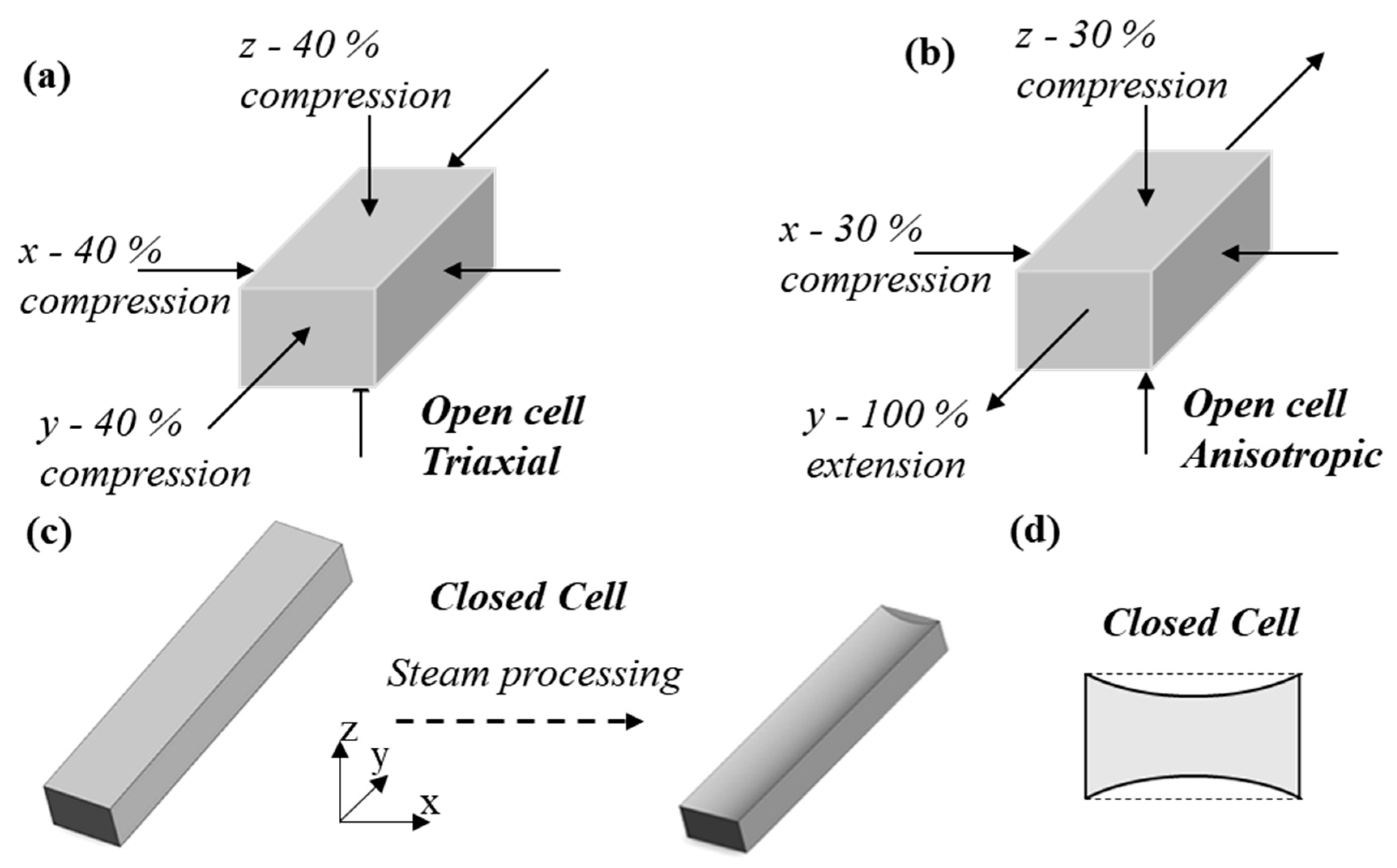
Figure 1. (a,b) Compression regimes for open cell foam fabricated with (a) triaxial and (b) anisotropic compression. (c,d) Closed cell foam (c) fabrication by steam processing and (d) imparted concave cross-section.
Applsci 11 01207 g001
Figure 2. Auxetic closed cell foam in compression test device, (a) uncompressed with target region for DIC; and (b) at 80% compression.
Applsci 11 01207 g002
Figure 3. Microscopic images of 1 to 2 mm thick slices of (a) unconverted open cell foam, (b) anisotropic open cell foam, (c) triaxial open cell foam. Inserts in (a) to (c) show single cells with underlying unconnected ribs removed. (d,e) Renderings from micro-computed tomographic of ~4 × 5 × 20 mm samples of (d) unconverted closed cell foam and (e) triaxial closed cell foam.
Applsci 11 01207 g003
Figure 4. (a,b) DIC contour plots of anisotropic open cell foam showing lateral strain (x-axis) used for Poisson’s ratio measurement at 2% compression (y-axis) and an applied strain rate of (a) 0.005 s−1, (b) 200 s−1; (c,d) DIC contour plots of anisotropic open cell foam showing axial strain (y-axis) at 2% compression and an applied strain rate of (c) 0.005 s−1, (d) 200 s−1; (e,f) Lateral vs. axial strain relationships for (e) open cell foams; (f) closed cell foams at applied strain rates of 0.005 s−1 and 200 s−1. Legend (RHS) is the same for (a) to (d).
Applsci 11 01207 g004
Figure 5. (a,b) Mean Poisson’s ratios of (a) open cell foams; (b) closed cell foams at applied strain rates of 0.005 s−1 and 200 s−1, measured to 2% compression. Error bars show 1 standard deviation.
Applsci 11 01207 g005
Figure 6. (a,b) Stress vs. axial engineering strain at minimum and maximum strain rates, for samples with median stress at 10% compression of (a) open cell and (b) closed cell foam. (c,d) Mean Young’s moduli of (c) open cell foams and (d) closed cell foams at minimum and maximum applied strain rates, measured to 2% compression, error bars show 1 standard deviation. Tested axis labelled for each foam.
Applsci 11 01207 g006
Publisher’s Note: MDPI stays neutral with regard to jurisdictional claims in published maps and institutional affiliations.