Article

Optical Design of the Goaly3 Multi-Mirror Telescope System with a Wide Field of View

1
School of Electronic and Optical Engineering, Nanjing University of Science and Technology, Nanjing 210094, China
2
Jiangsu Key Laboratory of Micro and Nano Heat Fluid Flow Technology and Energy Application, School of Physical Science and Technology, Suzhou University of Science and Technology, Suzhou 215009, China
3
School of Physical Science and Technology, Soochow University, Suzhou 215006, China
*
Authors to whom correspondence should be addressed.
Appl. Sci. 2021, 11(3), 1200; https://doi.org/10.3390/app11031200
Submission received: 27 November 2020 / Revised: 23 January 2021 / Accepted: 25 January 2021 / Published: 28 January 2021
(This article belongs to the Section Optics and Lasers)

Abstract

:

Featured Application

The Golay3 sparse aperture telescope designed in this paper can be carried on a satellite to realize Earth observation and remote sensing. A ground telescope with a larger aperture can also be designed with the method provided in this paper and used for astronomical observation.

Abstract

A Golay3 multi-mirror telescope (MMT) system is designed in this paper. The fill factor of the Golay3 MMT is derived from the angular resolution of the telescope. An initial configuration is established according to the paraxial optical theory. A three-element aspheric corrector group is designed and placed in the converging light cone to enlarge the field of view (FOV) of the Golay3 MMT. The tolerance analysis for each surface of the Golay3 MMT is conducted using the Monte Carlo method. The design results show the FOV of the Golay3 MMT system can be increased to 1.5° with the insertion of a three-element aspheric corrector group. The results of the tolerance analysis indicate that most tolerances are loose, while some decenter tolerances relating with the aspheric surfaces are relatively tight, but still within an acceptable range.

1. Introduction

The quest for finer angular resolution in astronomy will inevitably lead to larger apertures, which has pushed the limits of size and weight for monolithic primary mirrors. Large primary mirrors are increasingly difficult to fabricate and mount; moreover, they may even be impossible to launch for space-based systems. In response, technologies such as segmented and sparse aperture system are developed as the next generation of telescopes [1,2,3,4]. One type of sparse aperture systems is the multiple-mirror telescope (MMT) [5], such as the proposed Giant Magellan Telescope (GMT), in which the primary mirror consists of seven 8.4 m segments and the secondary mirror is segmented to match the primary mirror with seven 1.1 m segments [6]. The other is the multi-telescope telescope (MTT) system [7,8] in which all the sub-mirrors own their independent secondary mirrors. Compared with the MTT system, the MMT system does not need an expensive and complicated beam combiner to bring the light to a common focus [9]. However, the MMT system usually has a relatively small field of view (FOV) due to the co-phasing requirement of the sub-mirrors.
The MIT Adaptive Reconnaissance Golay3 Optical Satellite (ARGOS) demonstrated the practicality of a modular architecture for space-based optical systems for the first time with a FOV of 3–10 arcmins. In 2008, Wang et al. presented a MMT prototype [10] in which the spherical primary mirror consisted of eight annular sub-mirrors and one central mirror. The insertion of a four-element spherical corrector group before the image plane of the prototype achieves a FOV of 0.152°. Compared with conventional spherical and aspheric surfaces (secondary surfaces), free-form surfaces offer higher design freedom, allowing for better optical performance and larger field of view with fewer optical surfaces. However, because free-form surfaces are rotationally asymmetric, the assembly, detection and control of optical systems with free-form surfaces are more complex [11].
In this paper, we designed a Golay3 MMT with a wide field of view. The configuration of the Golay3 MMT is based on a Cassegrain system. The FOV of the Golay3 MMT is enlarged to 1.5° by adding a three-element aspheric corrector group in the converging light cone. In Section 2.1, we deduce the relationship between the fill factor F of the Golay3 MMT and the angular resolution. In Section 2.2 and Section 2.3, an initial configuration and a corrector group of the Golay3 MMT are designed. In Section 3, we evaluate the performance of the Golay3 MMT. In Section 4, we conduct a tolerance analysis for the Golay3 MMT. Finally, we conclude the paper in Section 5.

2. Design of the Goaly3 Multi-Mirror Telescope System

2.1. The Fill Factor of the Golay3 MMT

The Cassegrain configuration is adopted for the Golay3 MMT; the spherical primary mirror consists of three identical sub-mirrors, which are arranged in the Golay3 form as shown in Figure 1.
The fill factor F, which is defined as the ratio of all sub-mirrors’ area to that of the surrounding aperture, can be written as:
F = 3 · D s u b 2 / D 2
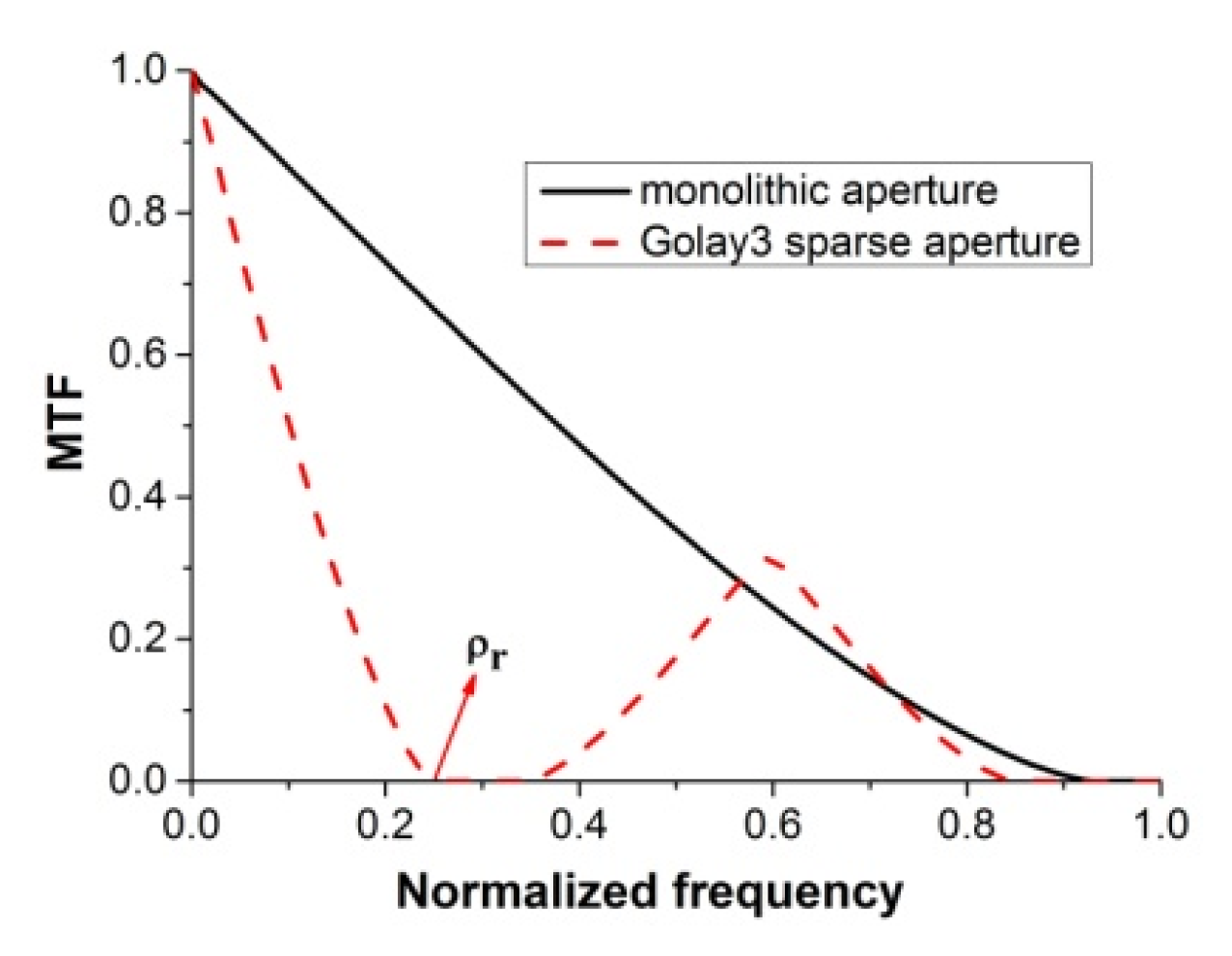
where Dsub and D are the diameters of the sub-mirrors and the surrounding aperture, respectively. For the sparse aperture system, the fill factor F varies from 0 to 1 (i.e., the monolithic aperture), and a larger F allows more light to enter the image plane through the sub-mirrors. Compared with the system with a monolithic primary, the Modulation Transfer Function (MTF) of a sparse aperture system suffers a contrast loss in the mid frequency range as shown in Figure 2, in which ρr denotes the first cutoff frequency. The angular resolution ϑ of the Golay3 sparse aperture telescope is given by:
ϑ = 1.22 λ D e q
In Equation (2), λ is the wavelength and f is the focal length. Deq is the equivalent aperture for the Golay3 MMT and defined as [7]:
D e q = 3 L + 4 D s u b 2 3 L 2 2
where L is the distance between the centers of the surrounding aperture and the sub-mirror. Combining Equations (1)–(3), the relationship between the fill fact F and the angular resolution ϑ is obtained:
F = 3 ( 2.44 λ ϑ 3 L ) 2 + 9 L 2 4 D 2
For diffraction-limited telescopes, the diameter of the Airy spot is proportional to the focal length provided that the aperture is determined. In addition, the F-number (the ratio of focal length to aperture) determines the compactness of the telescope, based on which the resolution of the telescope is set to 0.6 arcsecond and the F-number is given as 7. Since the aperture is 300, focal length is 2100 mm.
It can be deduced that the fill factor of the sparse aperture system is 29.6% and the semi-diameter of the sub-mirror is 46.2 mm. The detailed parameters of the Golay3 MMT are listed in Table 1.

2.2. The Initial Configuration of the Golay3 MMT

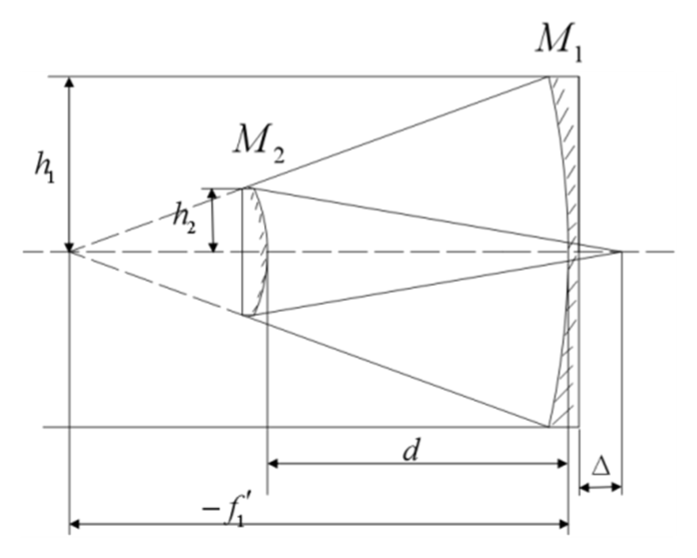
The design of the Golay3 MMT begins from a coaxial two-mirror system as shown in Figure 3, where M1 and M2 are the primary and secondary mirror, and their semi-diameters are represented by h1 and h2, respectively. The obstruction ratio α and the magnification of M2 β are defined as [12]:
α = h 2 h 1 = f 1 + Δ f 1 ( β 1 )
β = f f 1
In Equation (5), the parameter −f1 is the focal length of M1. The image working distance Δ is chosen to make sure the obstruction ratio α is minimum and the CCD detector has enough working space.
According to the paraxial optical theory, the radii of curvature of the two mirrors R1 and R2 can be obtained by:
R 1 = 2 f 1
R 2 = α β β + 1 R 1
d = f 1 ( 1 α )
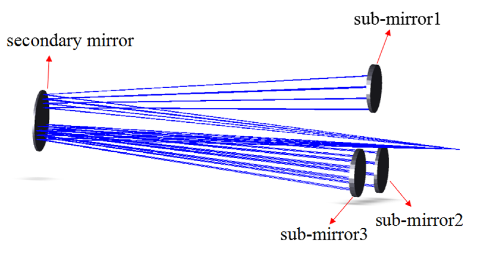
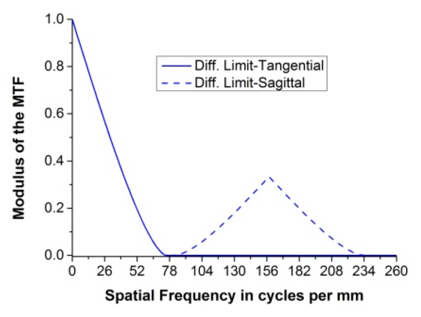
where d is the distance between M1 and M2. Finally, the monolithic primary mirror is substituted by three sub-mirrors as arranged in Figure 1. The configuration of the Golay3 MMT is shown in Figure 4 and its parameters are listed in Table 2. The conic constant of M2 is obtained by optimizing the system using the ZEMAX program. Figure 5 shows the diffraction-limited MTF of the initial configuration of the Golay3 MMT.

2.3. The Design of the Corrector Group

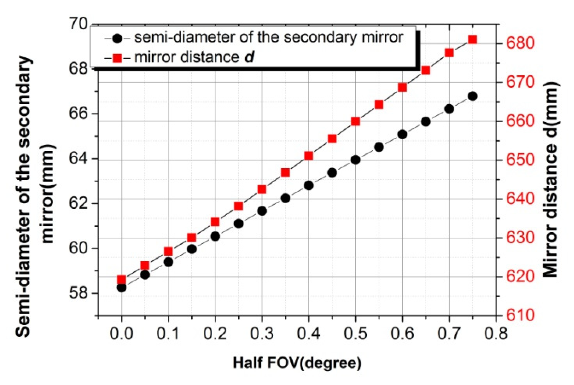
In addition to the spherical aberration from the primary mirror, the system suffers from such severe coma that it is limited to a very narrow FOV. With the increase of the FOV, the off-axis aberrations such as coma and astigmatism of the Golay3 MMT become dominant and the image quality is getting worse. Furthermore, the diameter of the secondary mirror also increases with a given mirror distance d (the black solid circle in Figure 6), which increases the obstruction of the secondary mirror.
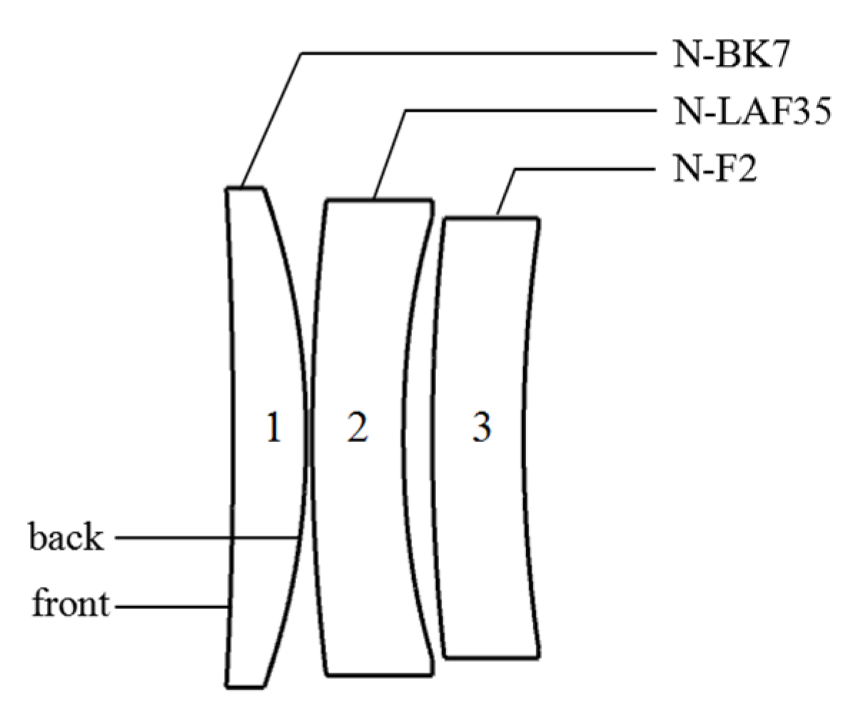
The corrector group is designed with three lenses to enlarge the FOV. The radii of the six surfaces are set as variables. The optimization is performed with the ZEMAX program to increase the FOV to 1.5° gradually.
During the optimization process, constraints of a 2100 mm focal length and a secondary mirror with a semi-diameter less than 62 mm are established. It is found that the mirror distance d increases with the increase of the FOV if the diameter of the secondary is fixed (the red solid box in Figure 7).
To reduce the chromatic aberration introduced by the corrector group, the refraction index and Abbe number of the three lenses are also set as variables. All the back surfaces of the three lenses are converted to the even aspheric with up to 8th-order terms to further improve image quality. The final configuration of the corrector group is shown in Figure 7 and their parameters are listed in Table 3.

3. Evaluation of the Performance of the Golay3 MMT

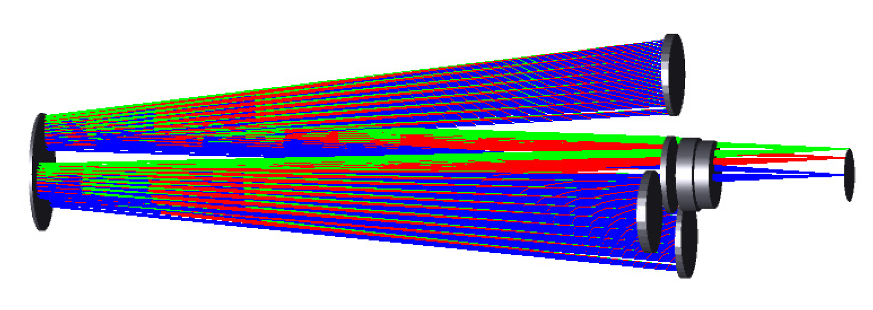
Figure 8 shows the configuration of the Golay3 MMT with the optimized corrector group. The parameters of the final system are listed in Table 4. The semi-diameter of the sub-mirror is 43.75 mm and the fill factor is 25.5%.
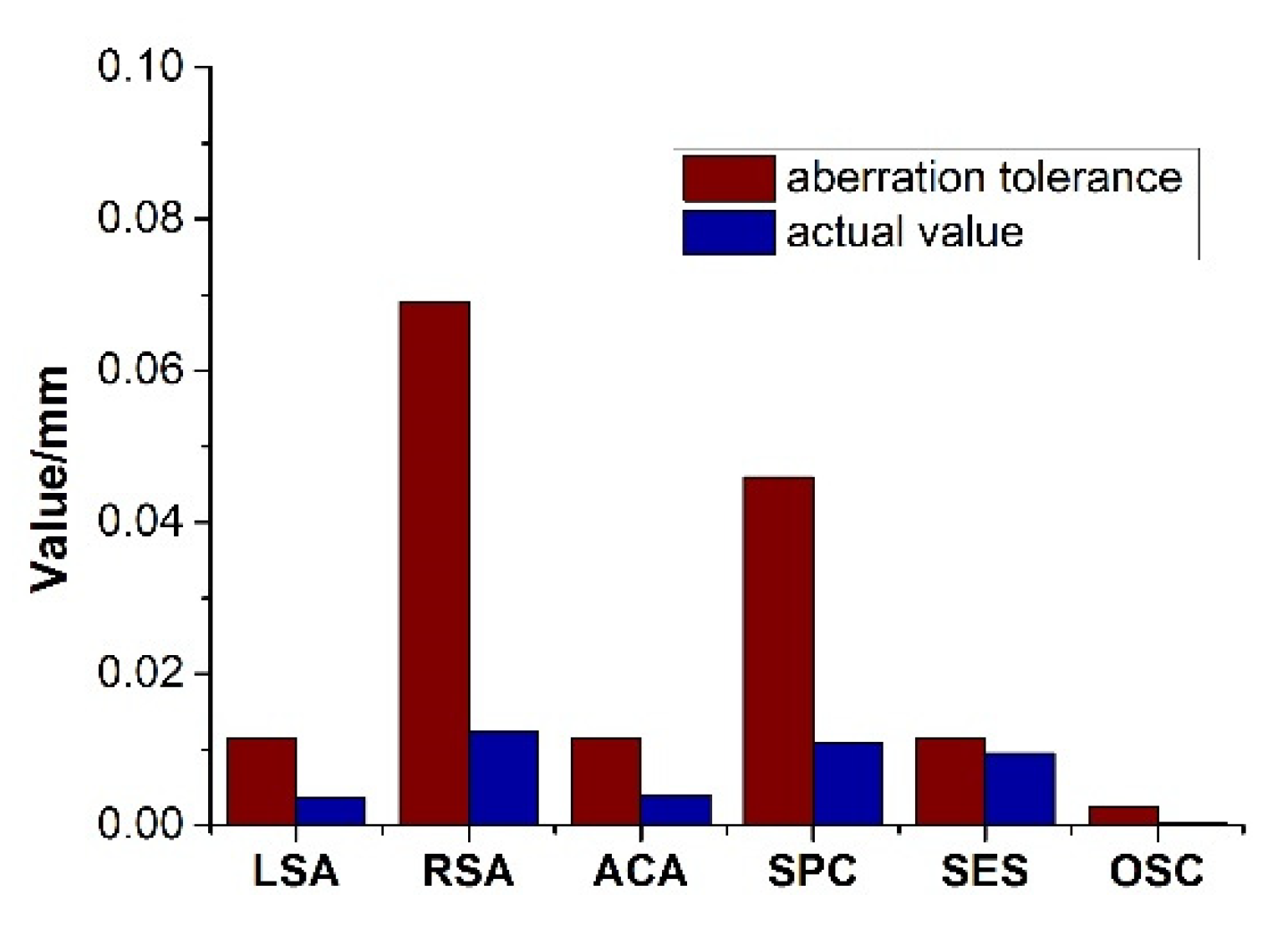
The aberration tolerances of the Golay3 MMT are evaluated by the wavefront error. According to the Rayleigh criteria [13], the performance is almost indistinguishable from perfect if the wavefront error is less than or equal to one-quarter of a wavelength. The tolerances of the geometrical aberrations corresponding to the wavefront error of one-quarter wavelength are calculated and their values are represented by the red bars in Figure 9. Acronyms LSA, RSA, ACA, SPC, SES and OSC represent the longitudinal spherical aberration (λ/n’sin2um), residual spherical aberration (6λ/n’sin2um), axial chromatic aberration (λ/n’sin2um), spherochromatism (4λ/n’sin2um), secondary spectrum (λ/n’sin2um) and offence against sine condition (usually <0.0025 mm), respectively. The parameter n’ refers to the refraction index in the image space, and um’ is the angle of the marginal ray in the image plane. These geometrical aberrations can be calculated by ray tracing and their values are represented by the blue bars in Figure 9. As can be seen from Figure 10, the values of the five geometrical aberrations are far less than their corresponding aberration tolerances.
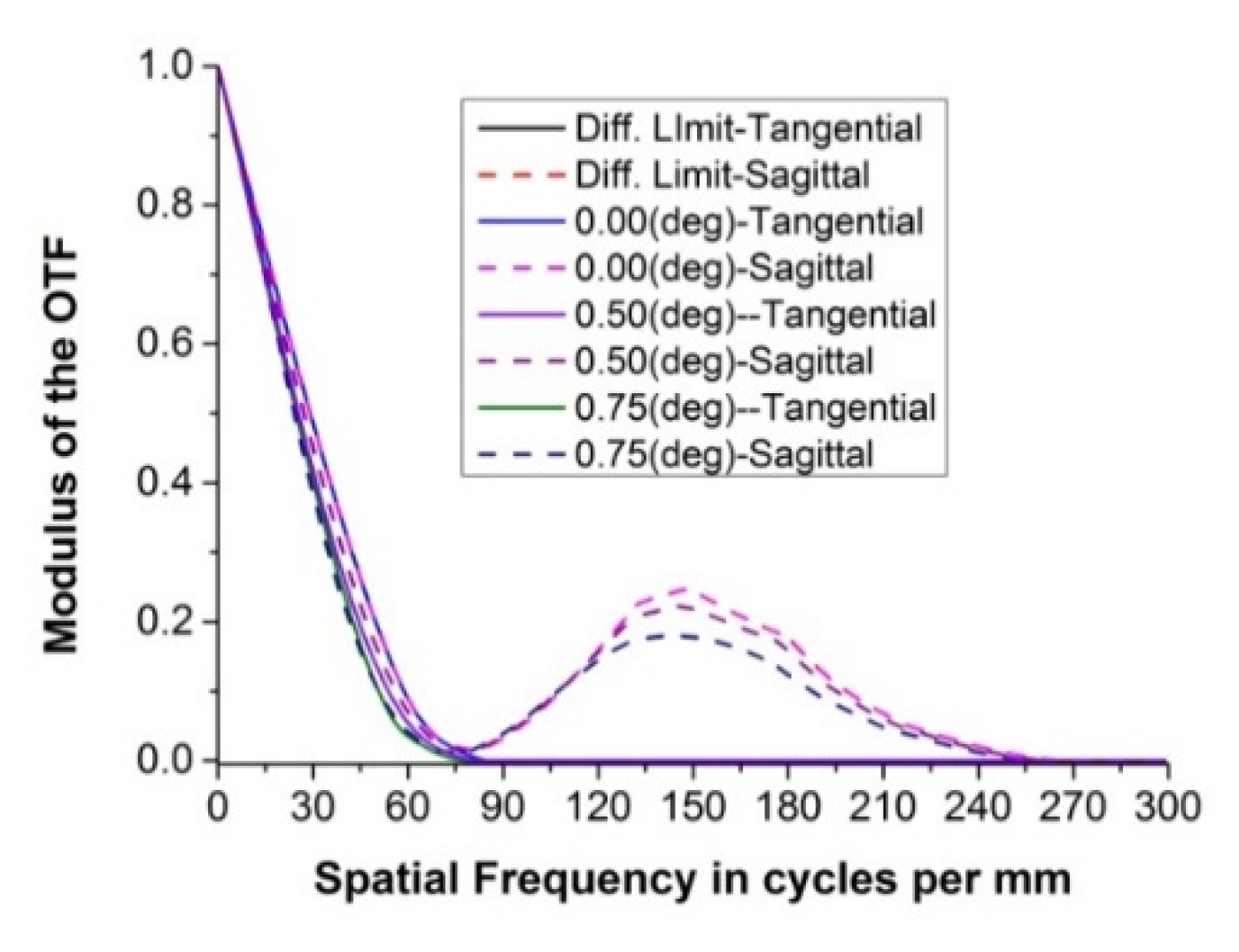
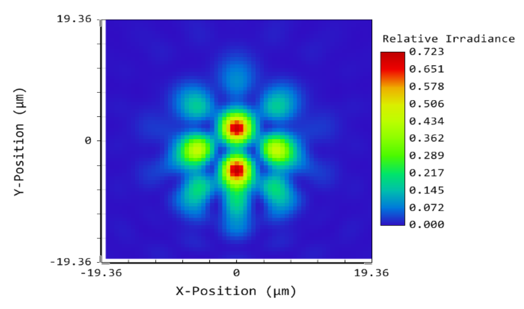
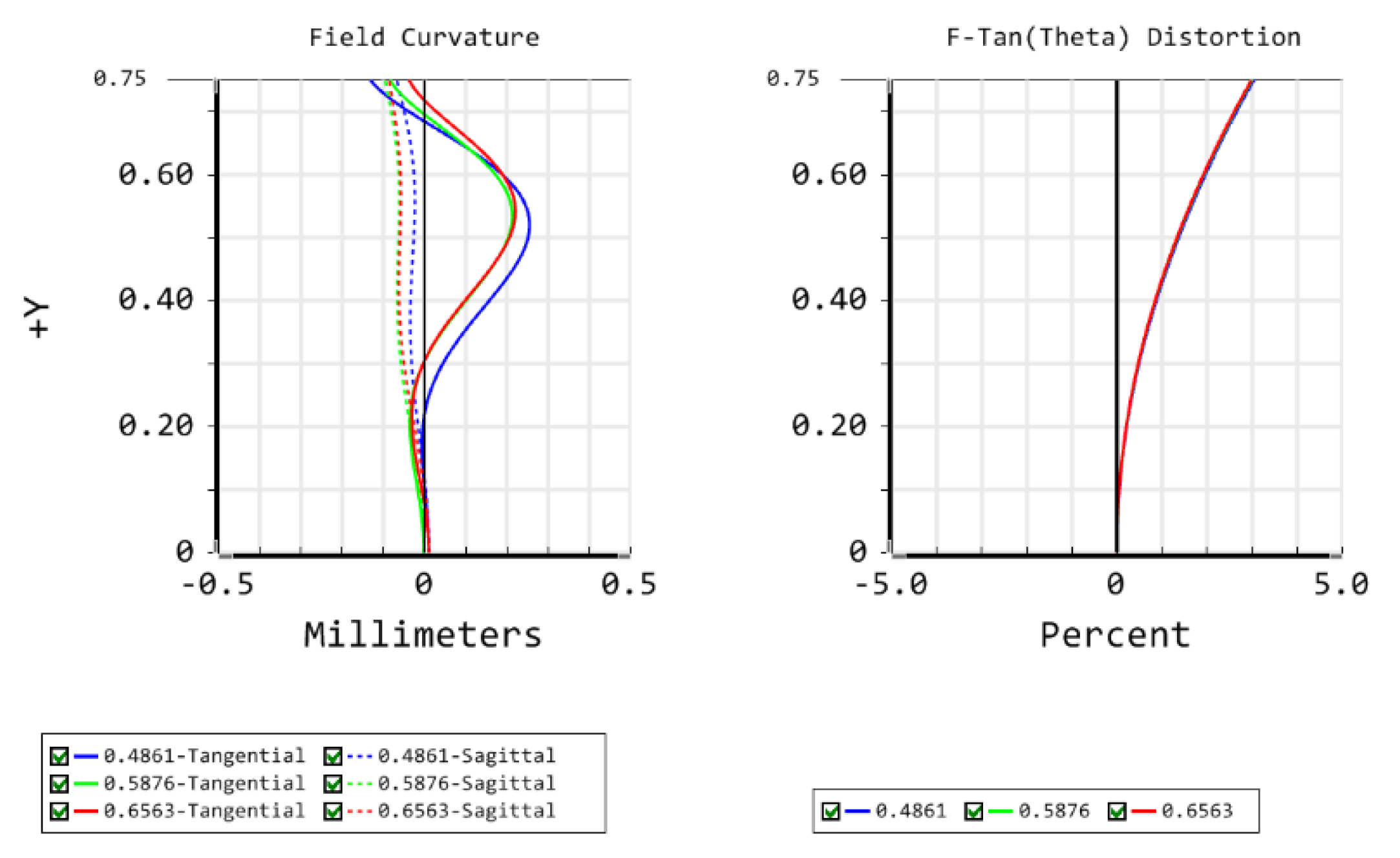
The MTF curves of the Golay3 MMT in Figure 10 indicate that the first cutoff frequency ρr in each field of view is around 80 lp/mm. The MTF values of different orientation in the mid and high frequency region (above 80 lp/mm) are different due to the asymmetry of the sub-mirrors’ distribution. A slight degradation in the sagittal MTF is observed in the mid and high frequency region when going to the outermost fields. The point spread function (PSF) for the most off-axis field is shown in Figure 11 and still delivers a nearly diffraction-limited performance. Though the final system satisfies all the design specifications, it should be noted that the image size is 56.65 mm in diameter, which means that a detector with several hundreds of millions of elements or an array of detectors is needed. From the field curvature curves in Figure 12, the field curvature in the tangential plane is more severe than its sagittal counterpart for the outer FOV (from 0.3° to 0.65°), with a maximum tangential shift of 0.255 mm. The maximum distortion of the Golay3 MMT is 3% for the outermost FOV.

4. Tolerance Analysis of the Golay3 MMT

Tolerance analysis plays an important role in optical design because it is directly related to the optical fabrication, alignment and cost. The tolerance analysis of the Golay3 MMT system is carried out using the Monte Carlo method. The criterion of the tolerance analysis is the sagittal MTF value decreasing less than 0.1 at 150 lp/mm (nominal 0.174). The thickness of the rear surface of lens 3 (i.e., the position of the image plane) is defined as the compensator. The analysis is repeated with tightening the tolerances with higher sensitivities and loosening the tolerances with lower sensitivities.
The results of the tolerance analysis are listed in Table 5. It was found that most parameters are flexible and insensitive. The surface and element decenter tolerances of corrector len1 and len2 are relatively more sensitive than other tolerances due to the aspheric nature of their back surfaces. However, these tolerances are still within a reasonable and acceptable range. With this tolerance budget, a Monte Carlo analysis was performed, and the results indicate that the probability of the sagittal MTF exceeding 0.11 is more than 90% at the frequency of 150 lp/mm. The maximum change in the back focus is 0.485 mm. The configuration of the sub-mirrors in the pupil plane determines that the telescope MTF has different values in different directions (sagittal and tangential). In the case of the Golay3 structure in Figure 1 in the paper, the contribution of sub-mirror 1 to the sagittal and tangential MTF is obviously different from that of sub-mirror 2 and sub-mirror 3. Therefore, when the criterion of tolerance analysis is determined, the tolerance value of each sub-mirror should be different. To ensure that Golay3 MMT achieves good thermal-mechanical stability, the mirrors are made of Silicon Carbide, and the mirror barrel and support structure are manufactured from invar.

5. Conclusions

In this paper, a Golay3 MMT based on the Cassegrain configuration was designed. The fill factor of the Golay3 MMT was derived from the angular resolution of the telescope. During the design process, a three-element aspheric corrector group was designed and placed in the converging light cone to enlarge the full FOV to 1.5°. The final Golay3 MMT achieved a fill factor of 25.5% and the performance of the system satisfied all the requirements of the design specifications. A tolerance analysis was performed using the Monte Carlo method. It was found that most tolerances were insensitive except for those decenter tolerances related with the aspheric surfaces. However, these tolerances were still within an acceptable range.

Author Contributions

Conceptualization, Q.W. and J.F.; methodology, J.F.; software, J.F.; validation, Q.W., L.L. and B.C.; formal analysis, J.F.; investigation, L.C.; resources, J.F.; data curation, B.C.; writing—original draft preparation, J.F.; writing—review and editing, L.L.; visualization, J.F.; supervision, L.C.; project administration, Q.W.; funding acquisition, Q.W. All authors have read and agreed to the published version of the manuscript.

Funding

The National Natural Science Foundation of China (NSFC) (61875145, 11804243); the Jiangsu Province Key Discipline of China’s 13th five-year plan (20168765); The Natural Science Foundation of the Jiangsu Higher Education Institutions of China (17KJA140001); the Jiangsu Province Key Laboratory (KJS1710).

Data Availability Statement

No new data were created or analyzed in this study. Data sharing is not applicable to this article.

Conflicts of Interest

The authors declare no conflict of interest.

References

  1. Fiete, R.D.; Tantalo, A.T.; Calus, J.R.; Mooney, J.A. Image quality of Sparse-aperture Designs for Remote Sensing. Opt. Eng. 2002, 41, 1957–1968. [Google Scholar] [CrossRef]
  2. Andersen, G. Holographic correction and phasing of large sparse-array telescopes. Appl. Opt. 2005, 44, 1355–1359. [Google Scholar] [CrossRef]
  3. Genet, R.; Rowe, D.; Clause, M.; Ridgely, J.; Lui, T.; Estrada, R.; Estrada, C.; Nidetz, M.; Holenstein, B.; Kenney, J.; et al. Sparse-Aperture Quasi-Meridian Telescopes. J. Double Star Obs. 2016, 12, 287–294. [Google Scholar]
  4. Schulz, T.J.; Paxman, R.G. Piston alignment for a segmented-aperture imaging system by using piston-sweep phasing. Opt. Lett. 2017, 42, 2922–2925. [Google Scholar] [CrossRef]
  5. Feng, W.; Quanying, W.; Lin, Q. Analysis of the characteristics of the Golay3 multiple-mirror telescope. Appl. Opt. 2009, 48, 643–652. [Google Scholar] [CrossRef]
  6. Johns, M. The Giant Magellan Telescope (GMT). In Proceedings of the SPIE Astronomical Telescopes + Instrumentation, Orlando, FL, USA, 23 June 2006; p. 26729. [Google Scholar]
  7. Chung, S.-J.; Miller, D.W.; de Weck, O.L. ARGOS testbed: Study of multidisciplinary challenges of future spaceborne interferometric arrays. Opt. Eng. 2004, 43, 2156. [Google Scholar] [CrossRef] [Green Version]
  8. Xie, Z.; Ma, H.; Qi, B.; Ren, G.; Shi, J.; He, X.; Wang, Z. Experimental demonstration of enhanced resolution of a Golay3 sparse-aperture telescope. Chin. Opt. Lett. 2017, 15, 41101–41104. [Google Scholar] [CrossRef] [Green Version]
  9. Dolkens, D.; Kuiper, J.M.; Cugny, B.; Sodnik, Z.; Karafolas, N. A deployable telescope for sub-meter resolutions from microsatellite platforms. In Proceedings of the International Conference on Space Optics—ICSO 2014, Tenerife, Spain, 17 November 2017; p. 05633. [Google Scholar]
  10. Zhi-Ying, L.; Yue-Gang, F.; Tian-Yuan, G.; Zhi-Jian, W. Effect of Sub-aperture Distribution on Optical Stitching System. Acta Photonica Sin. 2010, 39, 1775–1779. [Google Scholar] [CrossRef]
  11. Jun-Hua, P. New pan-Cassegrain telescope system. Opt. Precis. Eng. 2003, 11, 438–441. [Google Scholar]
  12. Jun-Hua, P. The Design, Manufacture and Test of the Aspherical Optical Surfaces; Suzhou University Press: Suzhou, China, 2004. [Google Scholar]
  13. Goodman, J.W.; Cox, M.E. Introduction to Fourier Optics. Phys. Today 1969, 22, 97–101. [Google Scholar] [CrossRef] [Green Version]
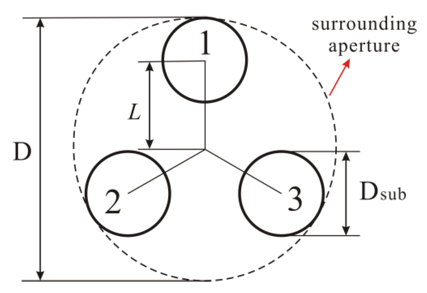
Figure 1. The Golay3 aperture.
Applsci 11 01200 g001
Figure 2. The Modulation Transfer Function (MTF) of the Golay3 aperture.
Applsci 11 01200 g002
Figure 3. The configuration of the two-mirror system.
Applsci 11 01200 g003
Figure 4. The initial configuration of the Golay3 MMT.
Applsci 11 01200 g004
Figure 5. The MTF of the initial configuration.
Applsci 11 01200 g005
Figure 6. The relationship between semi-diameter of the secondary mirror and half FOV. The relationship between the mirror distance and half FOV.
Applsci 11 01200 g006
Figure 7. The configuration of the corrector group.
Applsci 11 01200 g007
Figure 8. The configuration of the Golay3 MMT with the corrector group.
Applsci 11 01200 g008
Figure 9. The tolerances and actual values of different aberrations.
Applsci 11 01200 g009
Figure 10. The MTF of the Golay3 MMT.
Applsci 11 01200 g010
Figure 11. The PSF of the Golay3 MMT.
Applsci 11 01200 g011
Figure 12. The field curvature and distortion of the Golay3 MMT.
Applsci 11 01200 g012
Table 1. The parameters of the Golay3 MMT.
ParameterSpecification
Angular resolution (arcsecond)0.6
Diameter of the surrounding aperture (mm)300
Diameter of the sub-mirror (mm)46.2
Focal length (mm)2100
F/number of the system7
F/number of the primary3.5
Full field of view (degree)1.5
Spectral range (μm)0.486–0.656
Pixel size of the CCD (μm)6.2
MTFdiffraction limited
Table 2. The parameters of the initial configuration of the Golay3 MMT.
SurfaceRadius (mm)Thickness (mm)Semi-Diameter (mm)Conic
Sub-mirror−2100.0−641.646.20
Secondary mirror−1633.6816.858.25711.537
Table 3. The parameters of the three-element corrector group.
Corrector Lens123
MaterialN-BK7N-LAF35N-F2
Radius of curvature (front surface) (mm)−756.425329.505330.970
Radius of curvature (back surface) (mm)−140.597172.986243.969
Thickness (mm)12.00014.49915.000
Semi-Diameter (mm)40.98739.01736.088
Conic (back surface)000
4th-order term (back surface)−7.508 × 10−73.239 × 10−10−3.566 × 10⁻¹⁴
6th-order term (back surface)7.176 × 10−78.302 × 10−11−1.573 × 10⁻¹³
8th-order term (back surface)1.418 × 10⁻⁷−3.899 × 10−102.199 × 10⁻¹³
Table 4. The parameters of the final Golay3 MMT.
SurfaceRadius (mm)Thickness (mm)Semi-Diameter (mm)Conic
Sub-mirror−2100.0−674.22443.750
Secondary mirror−1291.344869.68662.50011.714
Table 5. The tolerance values of the Golay3 MMT.
Tolerance TypeSub-MirrorsSecondary
Mirror
Lens 1Lens 2Lens 3
FrontBackFrontBackFrontBack
Radius (mm)±0.05±0.05±0.05±0.05±0.05±0.05±0.05±0.05
Thickness (mm)±0.05±0.05±0.05±0.05±0.05±0.05±0.05
Element decenter X (mm)±0.1±0.1±0.05±0.05±0.1
Element decenter Y (mm)±0.1±0.1±0.05±0.05±0.1
Element tilt X (degree)±0.02±0.02±0.02±0.02±0.02
Element tilt Y (degree)±0.02±0.02±0.02±0.02±0.02
Surface decenter X (mm)±0.1±0.05±0.1±0.05±0.1±0.1
Surface decenter Y (mm)±0.1±0.05±0.1±0.04±0.1±0.1
Surface tilt X (degree)±0.02±0.014±0.02±0.016±0.02±0.016
Surface tilt Y (degree)±0.02±0.014±0.02±0.016±0.02±0.016
Refraction index±0.001±0.001±0.001
Abbe number±0.0642±0.0493±0.0364
Publisher’s Note: MDPI stays neutral with regard to jurisdictional claims in published maps and institutional affiliations.