Article

A Fluid–Solid–Heat Coupling Analysis for Water-Lubricated Rubber Stern Bearing Considering the Deflection of Propeller Shaft

1
State Key Laboratory of Mechanical Transmissions, Chongqing University, Chongqing 400044, China
2
School of Mechanical and Power Engineering, Chongqing University of Science and Technology, Chongqing 401331, China
*
Author to whom correspondence should be addressed.
Appl. Sci. 2021, 11(3), 1170; https://doi.org/10.3390/app11031170
Submission received: 11 November 2020 / Revised: 21 January 2021 / Accepted: 22 January 2021 / Published: 27 January 2021
(This article belongs to the Section Mechanical Engineering)

Abstract

:
The novelty of the present study is that it investigates the effect of propeller shaft deflection, caused by the propeller self-weight and interfacial mixed forces, on the fluid–solid–heat (FSH) coupling performance of water lubricated rubber stern bearing (WLRSB). In the FSH coupling model, the generalized average Reynolds equation and the Kogut–Etsion asperity contact model are used to determine the hydrodynamic and the elastic–plastic contact behaviors of WLRSB. In the thermal analysis, the journal, water film, and rubber bushing are considered as an integrated system (JWR system) using the Euler method. To prove the correctness of the developed model, the predicted results are verified by comparisons with the experimental results given in the literature. In addition, to assess the effect of the force-driven deflection during FSH simulation, comparisons of the FSH predictions between the aligned journal case and the deflected journal case are carried out. The results indicate that, especially under a heavy load condition, the deflection of the stern shaft should be incorporated into the lubrication gap between the journal–rubber interface during the analysis of FSH performance of the JWR system.

1. Introduction

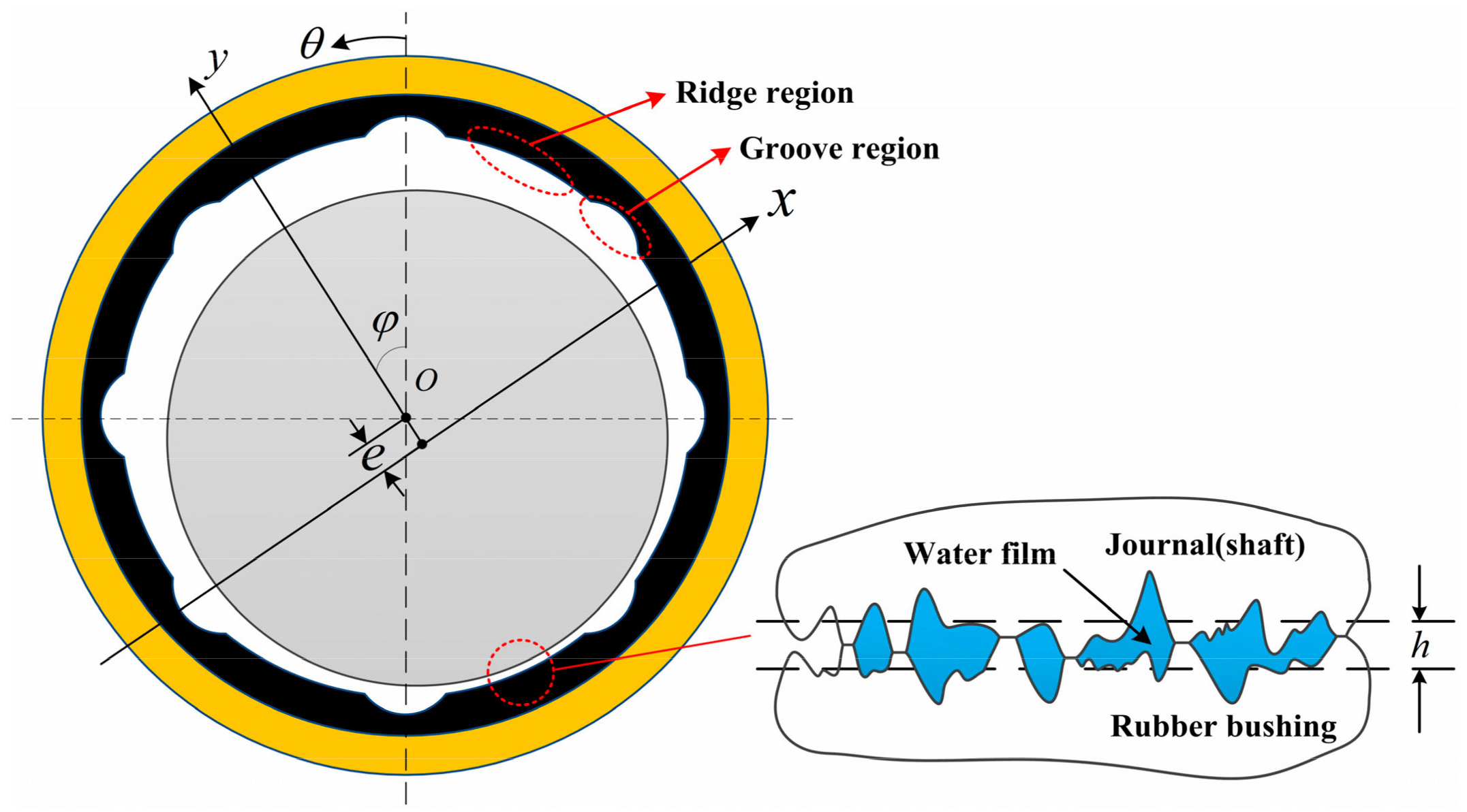
Water-lubricated rubber stern bearings, which are widely used in marine propulsion systems, have been attracting increasing attention owing to their excellent performance [1], such as low temperature rise, environmental friendliness, convenient assembly, etc. Figure 1 depicts a typical stern bearing lubricated with water, which exhibits a lower rate of viscous dissipation and a better cooling capacity compared with an oil-lubricated journal bearing [2]. However, the viscosity of water is extremely lower than that of mineral oil, implying that the hydrodynamic lifting generated by a water film is typically not able to support the external load [3,4,5], and therefore, asperity contact occurs at the journal–rubber interface [1,6], which affects the mixed friction behaviors by the generated frictional heat and thermal expansion. Therefore, the fluid field (from the hydrodynamic water film), solid field (from the asperity contact and elastic–thermal deformation), and thermal field (from the mixed friction heat) coexist (FSH coupling effect) at the journal–rubber interface. Consequently, a multi-field coupling numerical analysis of the water-lubricated stern bearings is necessary to investigate their reliability and failure mechanism. However, comprehensive theoretical works related to this topic are still limited.
Studies have been published to investigate the fluid–solid coupling performances (or mixed friction performances) of stern bearings [7,8,9,10,11,12,13]. He et al. [8] and Lv et al. [12] presented a mixed lubrication model for a misaligned marine stern tube bearing, in which the effects of cavitation, bend deformation of the propeller shaft, and the wall slip of thin film have been considered. Kraker et al. [9] investigated the Stribeck curves of water-lubricated bearings experimentally under a wide range of operating conditions. To improve the computation efficiency of the fluid–solid coupling model of journal bearings, a fast computing technology was developed by Han et al. [11] and Chan et al. [10]. However, the studies mentioned above ignored the thermal effects caused by the asperity contact behavior between the journal and the bush.
The thermal effects caused by fluid film shearing significantly affect the performance of a stern bearing and have been studied numerically and experimentally by scholars. The experimental results of the oil film temperature distribution presented by Majumdar et al. [14], Bouyer et al. [15], and Pierre et al. [16] demonstrated that the maximum temperature of oil film occurred near the maximum fluid pressure location, and that oil film temperature distribution was highly dependent on operating conditions such as the journal speed, external load, journal misalignment, etc. It is noteworthy that a hydrodynamic bearing system can be considered as a heat conduction coupling system during thermal analysis. Related studies were experimentally performed by Mitsui et al. [17], Fitzgerald et al. [18], and Wang et al. [19]. In the field of theoretical modeling, thermohydrodynamic analyses for journal bearings were performed by Yadav et al. [20], Sahu et al. [21], Sun et al. [22], Mishra et al. [23], Lin et al. [24], Hoon et al. [25], Pu et al. [26], and Li et al. [27]. For the thermal study of water-lubricated bearings, Feng et al. [28] numerically investigated the thermohydrodynamic performance of a water-lubricated bearing considering misaligned and turbulent effects. In their study, the asperity contact effect was absent and the misaligned effect was considered based on a predetermined misalignment value. More recently, Wodtke and Litwin [29] performed an interesting study to investigate, numerically and experimentally, the effects of forced axial flow on the thermal behaviors of multi-groove water-lubricated bearings, in which the journal was treated as aligned. These theoretical studies primarily focused on the thermal performance of the fluid film and assumed that the heat was only generated by the viscous shear of the fluid film. However, during operation, the asperity contact friction heat caused by the contact effect at the journal bearing interface affects the performance significantly. The aforementioned studies fail to evaluate the thermal behavior originating from the asperity contact effect. To predict the thermal performance of WLRSBs more accurately, in the present study, the heat generated by the contact effect has been integrated in the thermal analysis. Subsequently, a general transfer equation based on the Euler method was used for simulating the thermal behavior of the journal, water film, and rubber bushing (JWR) system.
It is noteworthy that misalignment caused by the deflection of the propeller shaft has been observed to be a familiar phenomenon in a stern bearing system because WLRSBs exhibit a larger length-to-diameter ratio compared with general journal bearings. Recently, the effects of journal misalignment on the performance of the journal bearing interface have been investigated by many scholars (He T et al. [8]; Chan et al. [10]; Lv et al. [12]; Bouyer et al. [15]; Pierre et al. [16]; Mishra et al. [23]; Litwin et al. [30]; Mallya et al. [31]). In these studies, He T et al. [8] and Sun J et al. [22] calculated the misalignment using the external load acting on the journal and concluded that the tribology performance of the bearing was sensitive to misalignment of the journal, especially under a large eccentricity ratio. Mallya et al. analyzed the effects of shaft misalignment on the stability of journal bearings, and the thermal effects due to viscous shearing of oil film were also included in Mallya’s study. Han et al. [11], Lv et al. [12], Litwin et al. [30], and Mallya et al. [31] investigated the tribology performance of a misaligned bearing numerically under given misalignment parameters, i.e., degree of misalignment and misalignment direction angle. In the current study, in order to obtain the misalignment of the propeller shaft more accurately, the external force applied to the end face of the WLRSB and the hydrodynamic and contact forces were combined to determine the deflection of the propeller shaft under the FSH coupling conditions.
The purpose of this study was to investigate the FSH coupling performance of a WLRSB when the force-driven deflected shaft is taken into account. In order to evaluate the deflection of the shaft more accurately, the segmented mixed forces along the axial direction (i.e., hydrodynamic and contact forces) serve as the input information in the deformation analysis of the shaft, and the superposition method is applied to attain the deflection of the propeller shaft. Subsequently, the FSH coupling model is coupled with the deflection model to identify the deflected shaft effect on the FSH predictions. The proposed model is validated by comparing it with published experimental results. Therefore, this study can provide a more practical model to predict the FSH coupling performance for WLRSBs.

2. Numerical Models

2.1. Governing Equation

The water film pressure of a WLRSB considering surface roughness effects and 3D viscosity distribution can be determined by the 3D generalized average Reynolds equation, which can be expressed as:
R B 2 θ ϕ θ G p h θ + z ϕ z G R p h z = ω ϕ c θ h I R J R + σ 2 ϕ s θ
where ϕθ and ϕz [4] are the pressure flow factor in θ and z directions, respectively; ϕc [32] and ϕs [4] are the contact factor and shear factor, respectively; ph is the water film pressure, ρW is the density of water, and η is the viscosity of water. Furthermore, ω is the speed of the journal, h is the average film thickness, and σ is the composite standard deviation of the rubber surface. In Equation (1), the parameters IR, JR, and GR can be determined by:
G R = 0 h y η y I R J R d y , I R = 0 h y η d y , J R = 0 h 1 η d y
where y indicates the radial coordinate along the cross-film direction.
The profile of the WLRSB is shown in Figure 2. As shown, the lubrication clearance can be evaluated as the sum of the average geometric gap considering the deflection of the propeller shaft, h0, the groove depth, hg, and the elastic/thermal deformation of the shaft and the bush, δJ and δR. Consequently, the water film thickness, h(θ, z, ΔT), is given by the following:
h ( θ , z , Δ T ) = h 0 ( θ , z ) + h g θ , z + δ J ( θ , Δ T , p ) + δ R ( θ , z , Δ T , p )
where z represents the axial direction shown in Figure 2, ΔT is the temperature rise at the coordinate of (θ, z), and h0 can be calculated as:
h 0 = C ( 1 + ε i cos ( θ φ ) )
where εi is the eccentricity ratio of the ith cross-section of the bearings, and C is the radial clearance of the bearing.
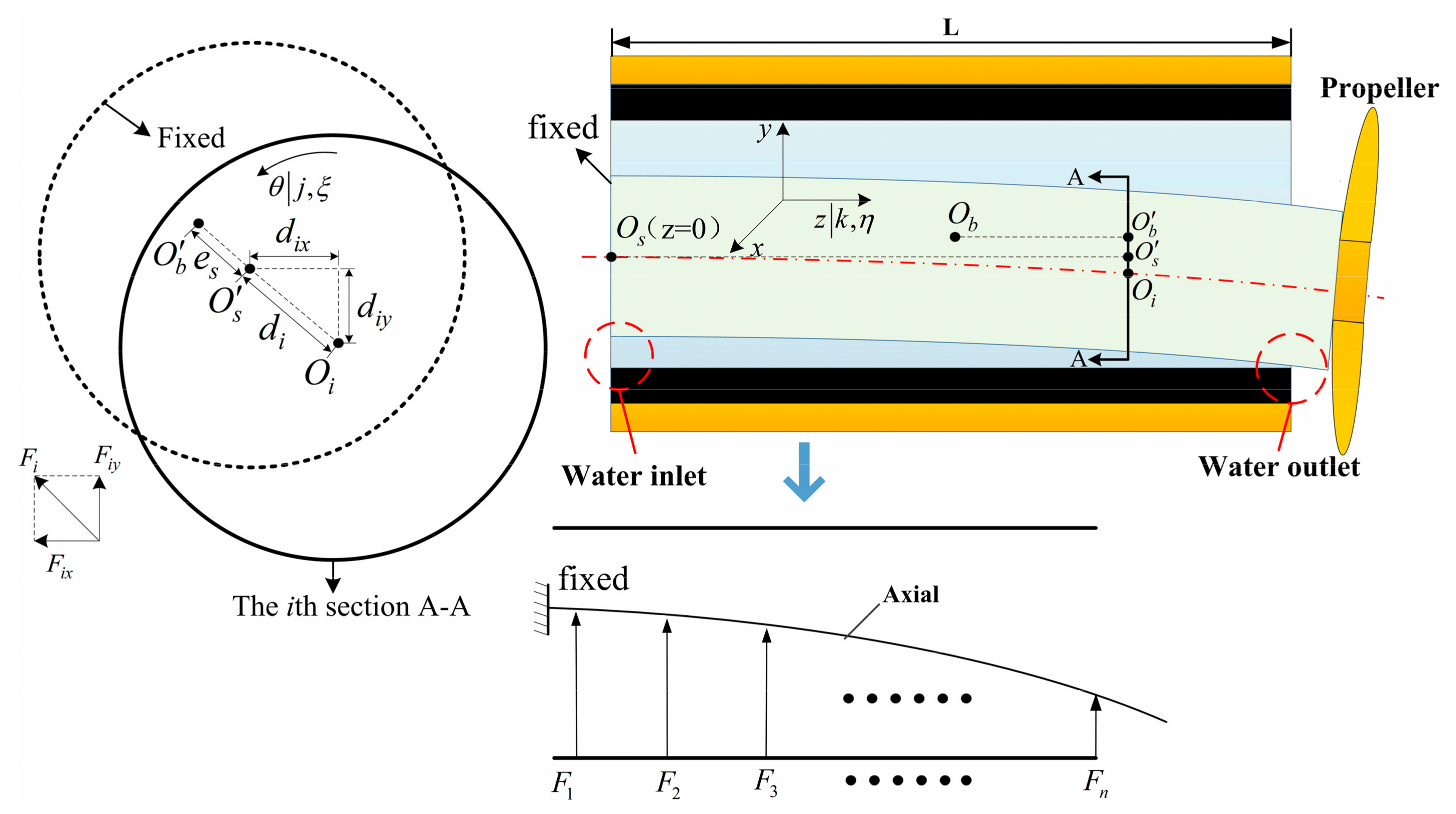
Figure 3 illustrates a schematic model of the deflected propeller shaft. In the force analysis of the propeller shaft, a simplification has been made so that the propeller shaft in the bearing hole is treated as a cantilever beam, which can be supported by two aspects. The first one is that the length-to-diameter ratio of the WLRSB is greatly larger than that of the general journal bearing, the second one is that the external load, i.e., the self-weight of the propeller, locates at the end face of the water-lubricated stern bearing. Additionally, a similar simplification was made in the study performed by He et al. [8]. As shown, the bearing is discretized using n girds in the axial direction, the shaft is simplified as a cantilever beam, and the end face of the bearing that is close to the propeller is assumed to be fixed. The force acting on the ith section of the shaft is defined as Fi, which is equal to the vector sum of Fiz in the z direction and Fix in the x direction. It is noteworthy that both Fiz and Fix comprise the hydrodynamic force component and the contact force component under FSH coupling conditions. The distances between the central point of ith section, Oi, and point O s (which corresponds to the projection of the central point of the fixed journal face, Os, on the ith section A-A) are defined as dix in the x direction and diy in the y direction, as shown in Figure 3. According to the superposition principle, dix and diy can be calculated using the following formula:
d i x = k = 1 i F k x z k 2 6 E J I 3 z i z k + k = i + 1 n F k x z i 2 6 E J I 3 z k z i d i y = M z i 2 6 E J I 3 L z i + k = 1 i F k y z k 2 6 E J I 3 z i z k + k = i + 1 n F k y z i 2 6 E J I 3 z k z i
where M is the self-weight of the propeller, L is the width of the bearing, EJ is the elastic modulus of the shaft, I is the inertia moment of the shaft section, and I = πD4/64, where D is the diameter of the shaft.
The eccentricity, ei, between the point Oi and the point O b , as shown in Figure 3, can be calculated as:
e i = d i + e s
where the distance di can be calculated by d i = d i x 2 + d i y 2 . Further, es is the eccentricity of the end face of the shaft. Subsequently, the εi in Equation (4) can be written as:
ε i = e i / C
The average geometric gap, h0, can be obtained by substituting Equations (5)–(7) into Equation (4).
When asperity contact occurs, the total pressure, p, acting on any nodal (θj, zk) of the stern bearing inner face consists of two parts: the water film pressure, ph, and the contact pressure, pc. The latter can be determined using the Kogut–Etsion elastic–plastic contact model [33], which is given by:
p c * = p c H B = 2 3 π σ β D K ω c * h * h * + ω c * I c 1.5 + 1.03 h * + ω c * h * + 6 ω c * I c 1.425 + 1.4 h * + 6 ω c * h * + 110 ω c * I c 1.263 + 3 K h * + 110 ω c * I c 1
where the superscript “*” denotes dimensionless parameters, HB is the hardness of the bush, whose unit is Pa; β and D are the curvature radius and the density of the asperity, respectively; and Ic is the integral operator, which is calculated by:
I c b = y * h * ω c * b ϕ * y * d z *
where ϕ*(y*) can be expressed as:
ϕ * y * = 1 2 π σ s σ exp 0.5 σ s σ 2 y * 2
where σs is the surface roughness of the shaft, and the value of σs/σ is set to 1.0 in the present simulation. In Equation (8), the dimensionless parameters ω c * and K can be calculated by the following expressions:
ω c * = π K H B 2 E c 2 β / σ ,   K = 0.454 + 0.41 ν B
where Ec is the composite elastic modulus and νB is the Poisson ratio of the bush.
The deformation of the bearing, δR, can be expressed as the sum of the elastic deformation, δRE, and the thermal deformation, δRT. The elastic deformation of the journal, δJE, can be ignored because its elastic modulus is significantly larger than that of the rubber bushing. Additionally, the thermal deformation of the journal, δJT, is assumed to be a linear thermal expansion so as to simplify the analysis. Consequently, the deformation equations of the journal and the rubber bushing are given as follows:
δ R E θ j , z k = ξ η G R E θ j , z k , θ ξ , z η × p h θ ξ , z η + p c θ ξ , z η δ R T θ j , z k = ξ η ζ G R T θ j , z k , θ ξ , z η , r ζ × Δ T θ ξ , z η , r ζ δ J T θ j , Δ T J = α J Δ T j r j 1 + ε j cos θ j φ
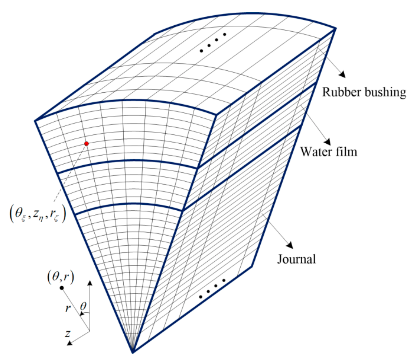
where the node (θξ, zη, rζ) is shown in Figure 4; ΔT(θξ, zη, rζ) is the temperature rise of the rubber bushing at the nodal of (θξ, zη, rζ), and GRE(θj, yk, θξ, yη) and GRT(θj, zk, θξ, zη, rζ) represent the influence functions of the elastic and thermal deformations, respectively. The calculated method of the former is presented by Chan et al. [10], and that of the latter can be referred to in Ref. [34].
In the thermal analysis, the journal, water film, and rubber bushing are treated as a heat conduction coupling system (JWR system for simplicity), as shown in Figure 4, using the Euler method. Based on this, the thermal behavior of the water film, propeller shaft, and rubber bushing can be described by a general transfer equation in polar coordinates, which is given by:
ρ C P v r T r + v θ T r θ + v z T z = r k r T r + r θ k θ T r θ + z k z T z + Φ
where ρ is the density of the rubber bushing (ρR), journal (ρJ), or lubricant (ρW); CP is the specific heat of the bushing (CPR), journal (CPJ), or water (CPW); kr(krR, krJ, krW), kθ(kθR, kθJ, kθW), and kz(kzR, kzJ, kzW) denote the thermal conductivities in r, θ, and z directions, respectively; vr, vθ, and vz denote the velocity at which the rotation speed corresponds to the journal and the flow velocity corresponds to the water in r, θ, and z directions, respectively.
One study [29] pointed out that the thermal behaviors of water-lubricated bearings depend significantly on the intensity of the enforced axial flow. In the present study, we assume the axial flow is sufficiently low, and therefore, the effect of the axial flow on the thermal behavior of the water-lubricated bearing is neglected in the current simulation.
Subsequently, the flow velocity in the θ direction, v, and in the z direction, vWz, is given as follows:
v W θ = u + u ϕ s I 0 h 1 η d ς ϕ θ p h x 0 h z m ς η d ς v W z = ϕ z p h z 0 z z m ς η d ς
where u is the linear velocity of the journal, u = ωR1. Furthermore, the parameter zm can be evaluated by zm = IR/JR.
The heat source in the JWR system is composed of the viscous shear heat of the water film, ΦW, and the friction heat, ΦC, generated from the asperity contact occurring at the journal–rubber interface, which can be described by the following formulas:
Φ C = μ c p c u Φ W = η v W θ θ 2 + v W z z 2
where μc denotes the friction coefficient of the asperity contact, and its value was assumed to be 0.15 in this study. Subsequently, the heat source, Φ, can be obtained as follows:
Φ = Φ W d V + Φ C d A d V
In Equation (16), dV is the differential volume for the water film, and its corresponding area at the journal–rubber interface is represented as dA. Consequently, the thermal properties of the JWR system can be determined by coupling Equations (13)–(16). Similar to the evaluation of the thermal deformation, the influence function method was also employed to obtain the temperature distribution of the JWR system. The corresponding influence functions can be referred to in Ref. [34].
The effect of the temperature rise on the water viscosity can be evaluated by:
η θ , z , r = 1.005 × 10 3 T W θ , z , r 293 8.9 e 4700 1 / T W θ , z , r 1 / 293
where η(θ, z, r) and TW(θ, z, r) are the 3D average viscosity and 3D average temperature of the water film along the radial direction, respectively. It should be noted that the unit of the temperature is K in Equation (17).
Once the hydrodynamic and asperity contact pressures are obtained, the external force acting on the propeller shaft can be calculated as follows:
F x = 0 L 0 2 π p θ , z sin θ φ R B d θ d z F y = 0 L 0 2 π p θ , z cos θ φ R B d θ d z
where Fx and Fy represent the force, including hydrodynamic and contact forces, in the x and y directions, respectively. Subsequently, the load capacity can be described by F = F x 2 + F y 2 , which is equal to the external force M.
The friction force, Ff, considering the water film shearing in the circumferential direction and the asperity contact at the journal–rubber interface can be estimated by:
F f = 0 L 0 2 π η ω R 1 2 h + h 2 p h θ d θ d z + 0 L 0 2 π μ c p c θ , z R B d θ d z
where ω is the rotation speed of the propeller shaft. Subsequently, the average friction coefficient, μ, that combines the effects of viscous shearing and asperity contact is given by:
μ = F f F

2.2. Boundary Condition

In this study, the following fluid pressure boundary condition is applied to solve the average Reynolds equation:
p h θ , 0 = p h θ , L = 0 p h 0 , z = p h 2 π , z p h θ 0 = 0 , p h θ 0 / θ = 0
where θ0 is the interface between the pressured region and the cavitation region.
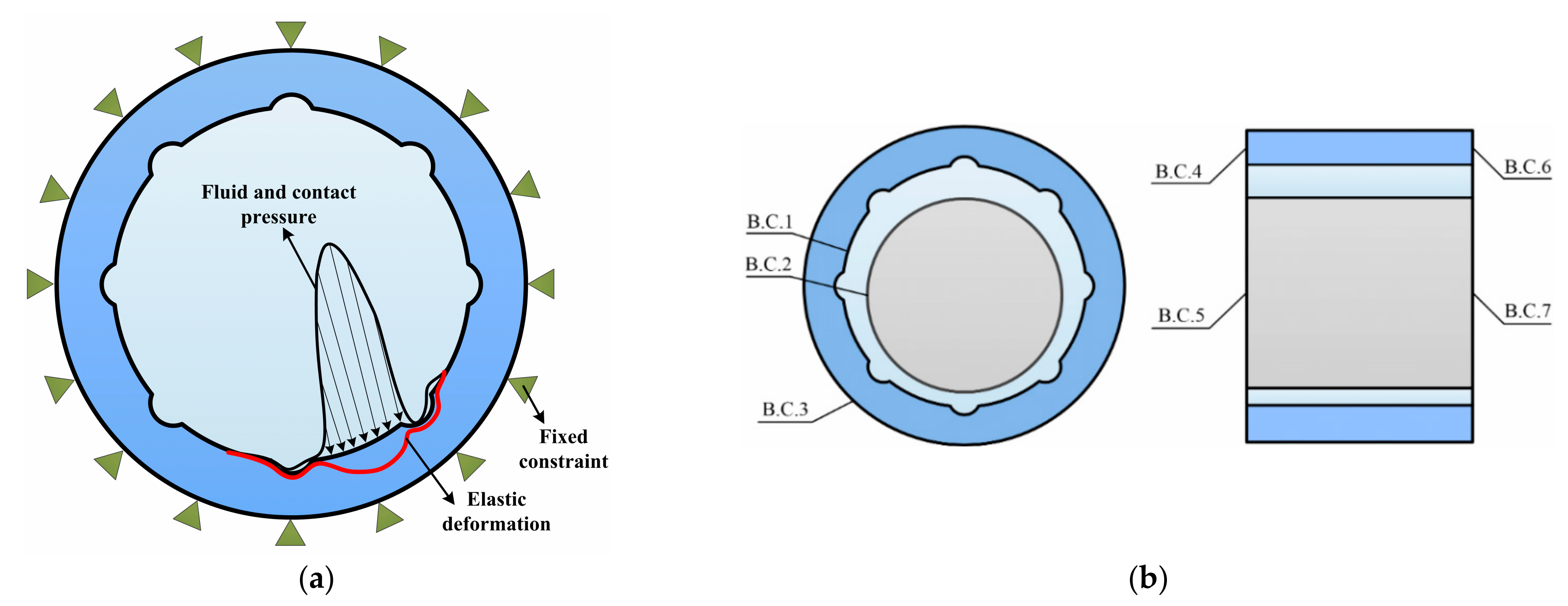
For simulating the elastic deformation, the outer surface of the bearing bush, which connects with the bearing house shown in Figure 1, is assumed to be fixed, as shown in Figure 5a, while all of the other boundaries in the calculation of elastic deformation are considered as elastically free. The thermal boundary conditions for the JWR system, shown in Figure 5b, can be classified into two categories.
(1)
Internal boundary conditions: B.C.1 and B.C.2 represent the bearing–water and water–journal interfaces; which can be evaluated by the following Equation (22).
T W = T B , k r L T W r = k r B T B r   ( BC 1 ) k r J T J r = 1 2 π k r L 0 2 π T W θ   ( BC 2 )
It should be mentioned that the journal is treated as isothermal along the circumferential direction.
(2)
External boundary conditions: B.C.3 through B.C.7 are the external boundaries for the system and they must be specified. In the present thermal model, the convective boundary is applied to describe the thermal behavior at B.C.3–B.C.7, which is given by:
k T n = h h T c T         r , θ , z Γ 3
where Tc and T represent the water inlet and ambient temperatures, respectively, and hh denotes the convective heat transfer coefficient.

2.3. Numerical Algorithm

The discrete form of the average Reynolds equation (Equation (1)) can be obtained by finite difference method and the obtained linear equations at each unknown pressure nodes are given by:
A j 1 , k p h j 1 , k + A j + 1 , k p h j + 1 , k + A j , k 1 p h j , k 1 + A j , k + 1 p h j , k + 1 A j , k p h j , k = B j , k
The successive overrelaxation (SOR) method was used for solving Equation (24), which is described by:
p h new = p h old + λ p ˜ h new p h old
where p ˜ h new = B j , k old A j 1 , k p h j 1 , k old A j + 1 , k p h j + 1 , k old A j , k 1 p h j , k 1 old A j , k + 1 p h j , k + 1 old / A j , k , and λ is the relaxation factor—its value is assumed to be 1.5 in the current simulation.
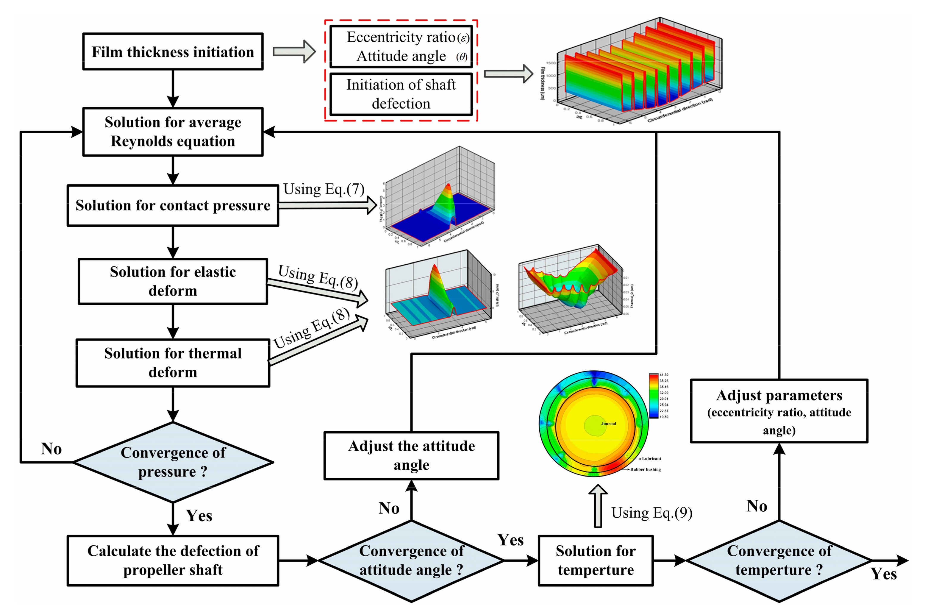
The flow chart used to simulate the fluid–solid–heat coupled performance of the JWR system is illustrated in Figure 6, which includes a procedure for the calculation of fluid pressure, contact pressure, thermal–elastic deformation, temperature distribution, and shaft deflection. In the present study, a calculation procedure based on Fortran is developed to determine the FSH coupling performance of the water-lubricated rubber bearing considering propeller shaft deflection. After numerical testing at a computer with a 1.61 GHz CPU and 16 GB RAM, it was observed that the evaluation time for the bearing properties is around 30 min. Furthermore, it is worth mentioning that for the statistical hydrodynamic and contact models, only the average Reynolds equation was calculated for the hydrodynamic lubrication regime; however, both the average Reynolds equation and asperity contact model were calculated for the mixed friction regime.
The pressure, including the water film pressure and contact pressure, is controlled by the error given in Equation (26). The temperature and attitude angle are controlled by the error given in Equations (28) and (29), respectively.
j = 1 n k = 1 m p j , k new p j , k old j = 1 n k = 1 m p j , k old 1.0 × 10 6
T max old T max new T max old 1.0 × 10 6
where Tmax = (TJmax+TWmax+TRmax)/3, with TJmax, TWmax, and TRmax being the maximum temperature of the journal, water film, and rubber bushing, respectively.
θ new θ old / θ old 1 × 10 6
The attitude angle can be adjusted by the force component in x and y directions, which is given by:
θ new = θ old + arctan F x F y

3. Results and Discussion

3.1. Model Validation

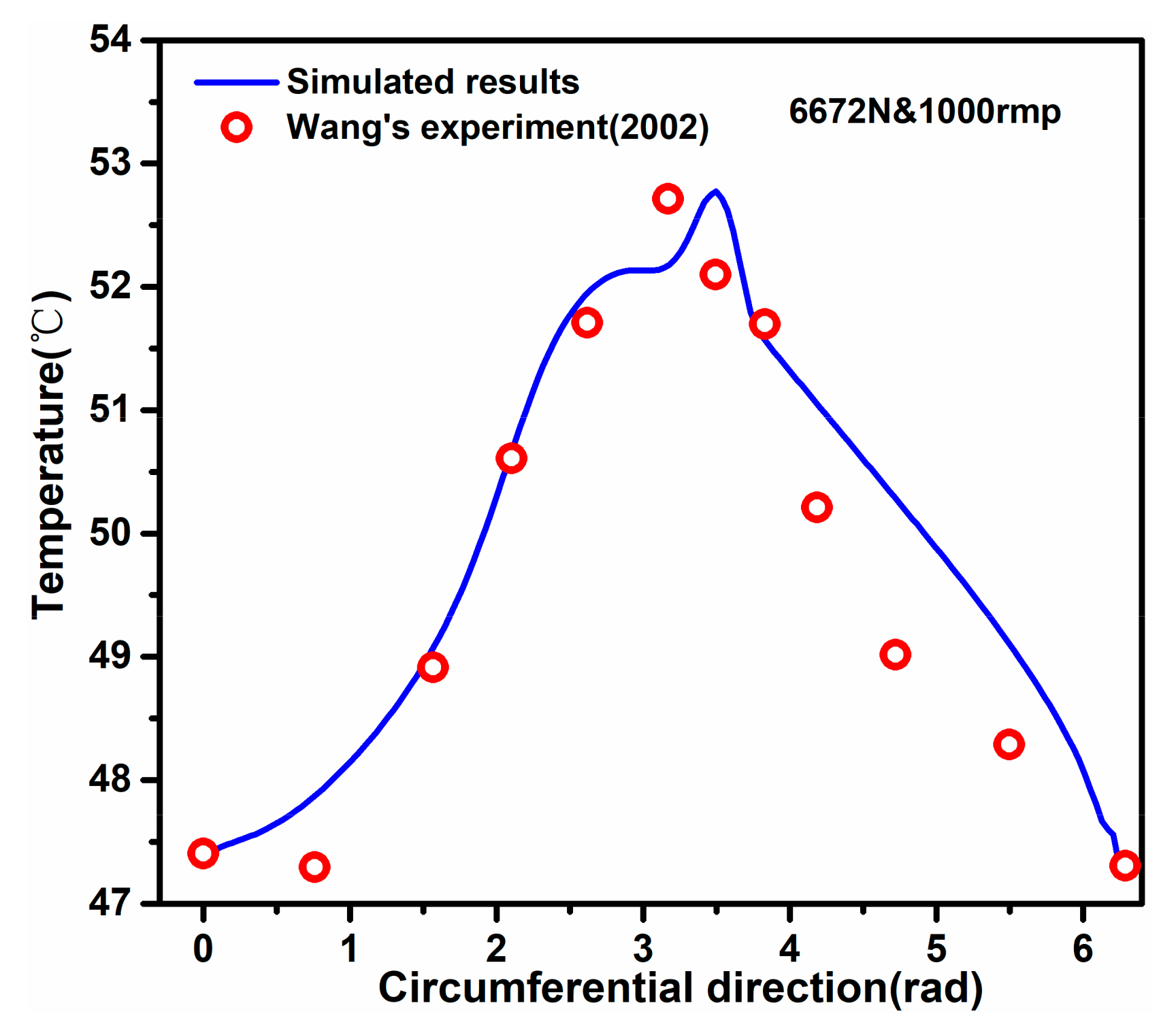
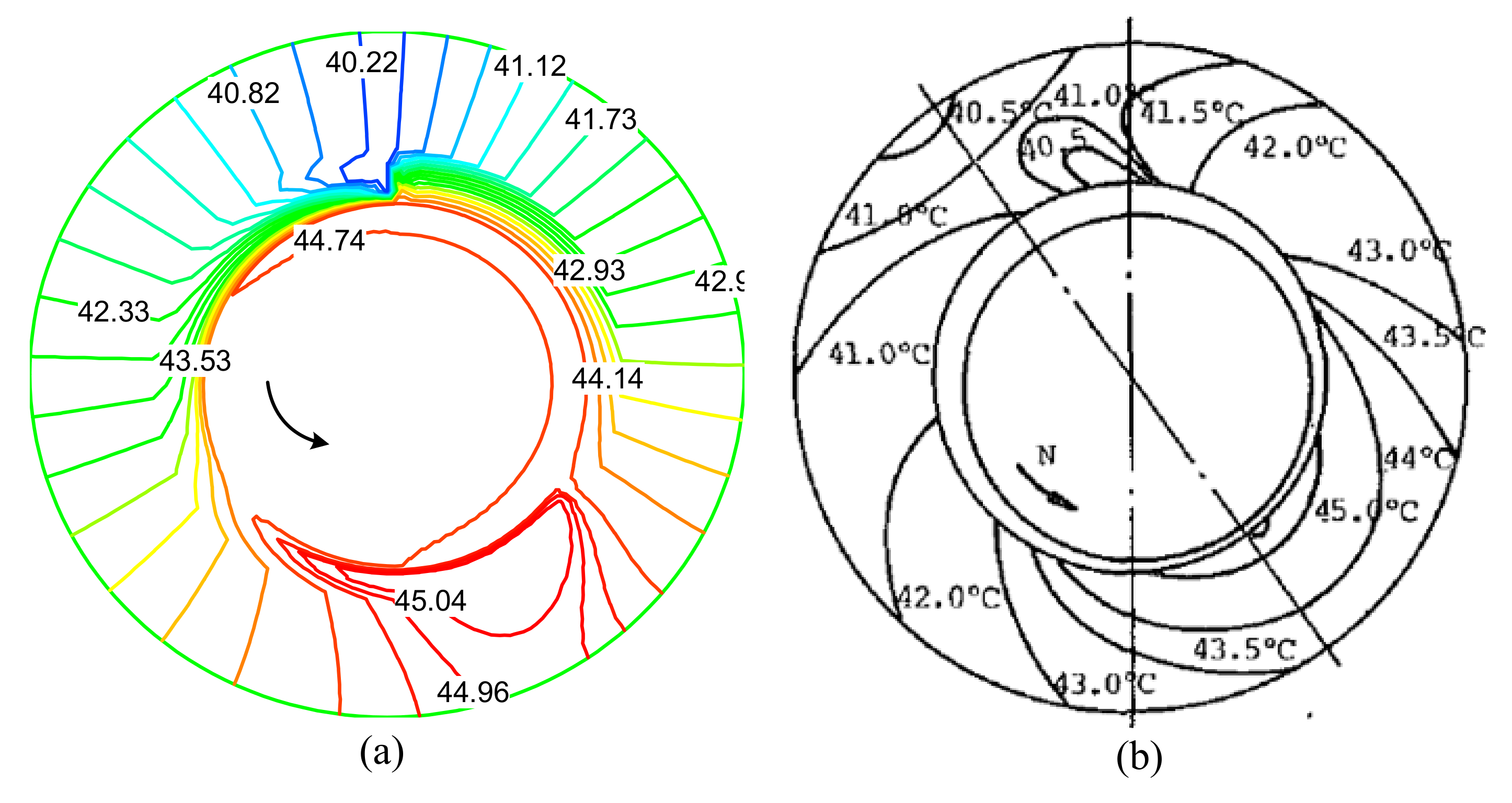
In order to validate the FSH coupling model, the journal bearing parameters given by Wang et al. [19] were used to obtain the temperature distributions under different external loads. As shown in Figure 7, a comparison of the temperature distribution between the present model and the experimental data provided by Wang et al. [19] was performed. A good agreement can be found between the predicted results and the experiment data. Verification of the thermal distribution of the bearing–lubricant–journal system was carried out by comparison with Mitsui’s experiment results (Mitsui et al. [17]), as shown in Figure 8, and the geometry, material, and lubricant parameters used in the presented model are consistent with those from Mitsui’s experiment. It was observed that the maximum temperature predicted by the present model agrees well with that tested by Mitsui, and the distribution trends of the temperature obtained by the developed model agree well with those given in Mitsui’s experiment. Therefore, the comparisons of the temperature distribution support the correctness of the developed thermal model.
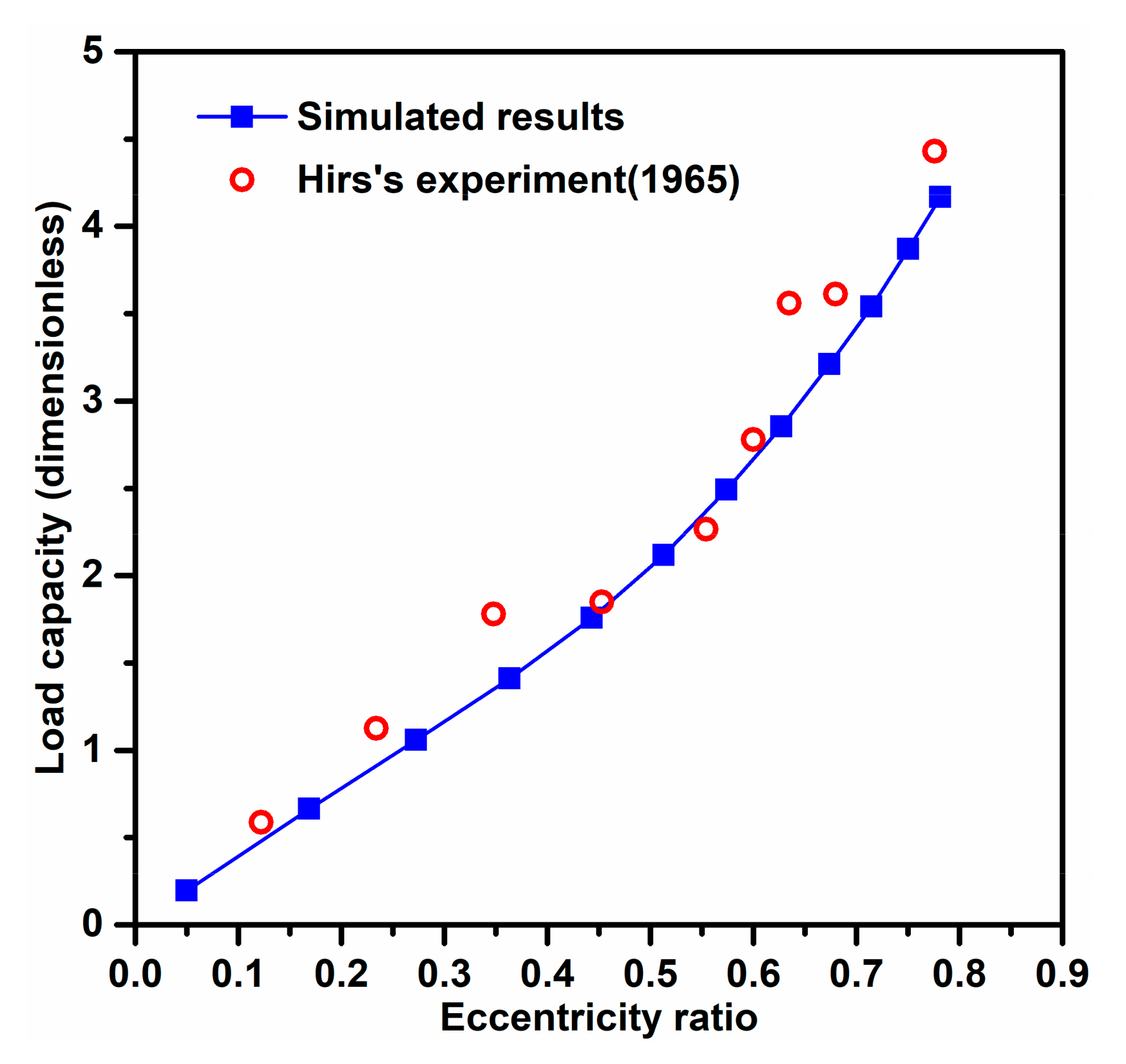
The proposed model was further validated by comparing the predicted load capacity with the experiment results from Hirs et al. [35]. Similarly, the geometry, material, and lubricant parameters used in the simulations were all the same as Hirs’ parameters. As shown in Figure 9, the load capacities under various eccentricity ratios agree well with those given in Hirs’ experiment [35]. Consequently, the comparisons above demonstrate the correctness of the present model, and therefore, it can be used to analyze the FSH coupling performance of the WLRSB.
In this study, the basic parameters, including the dimensions, materials, thermal parameters, and surface texture of the JWR system, used in the proposed model are listed in Table 1.

3.2. The Effects of Deflection of Propeller Shaft on Pressure and Deform Distribution

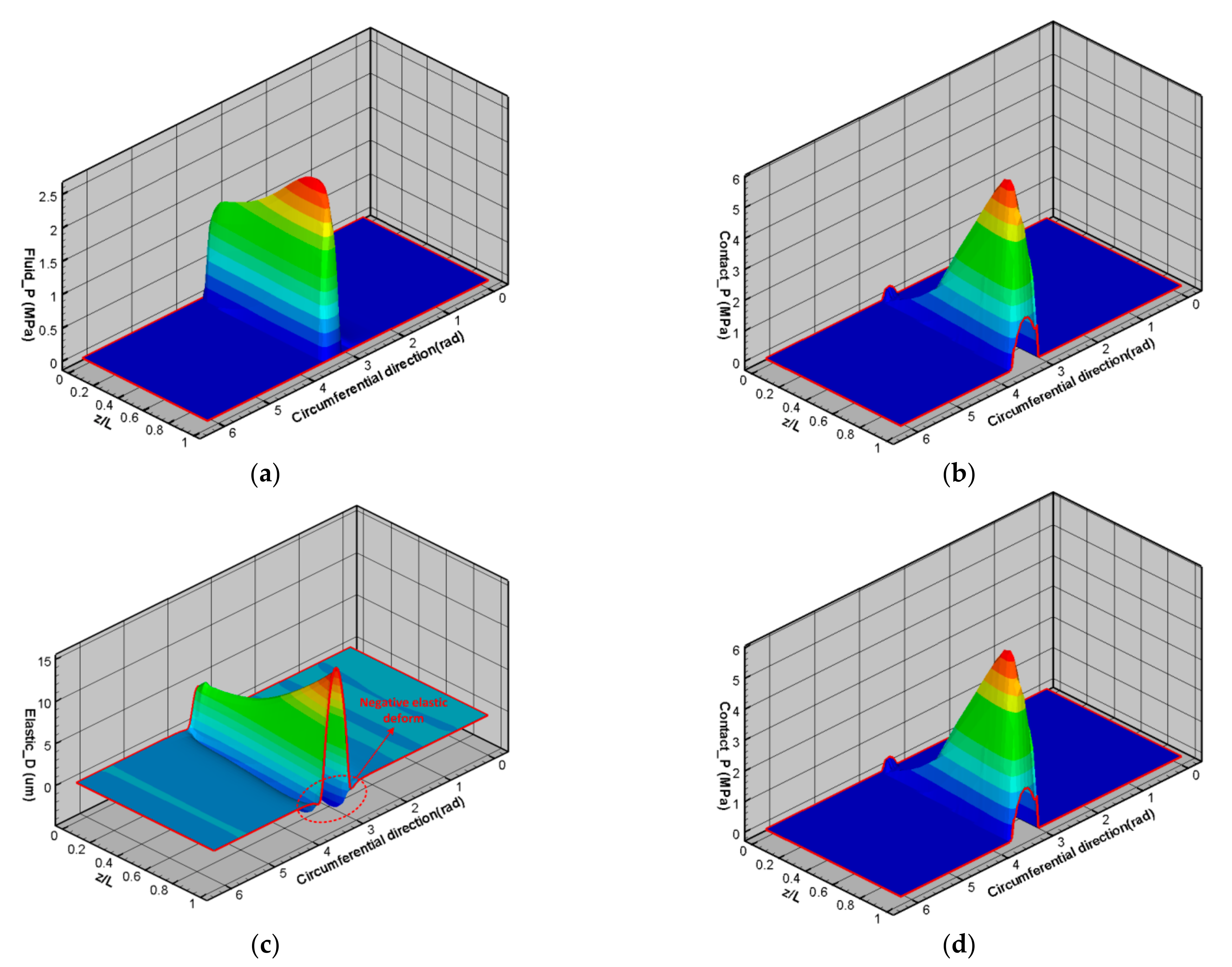
Figure 10 shows the distribution of the water film pressure, contact pressure, elastic deformation, and thermal deformation under the deflected propeller shaft. Figure 10a shows that the deflected shaft causes asymmetric hydrodynamic pressure distribution. By comparing the results plotted in Figure 10a, it was found that the external force is mainly carried by the asperity contact in the current simulated case, which demonstrates that the asperity contact plays a crucial role in the actual operating condition of the WLRSB. The results shown in Figure 10 indicate that the maximum fluid pressure, contact pressure, elastic deformation, and thermal deformation are mainly located on the water outlet side when the deflection of the propeller shaft is considered. This is because the deflected shaft decreases the lubrication gap close to the water inlet, thereby resulting in an increase in hydrodynamic pressure, asperity contact, and frictional heat. Figure 10c shows that negative elastic deformation occurs near the maximum elastic deformation; this is due to the fact that the rubber can be treated as an incompressible material owing to its Poisson’s ratio being near to 0.5. Moreover, Figure 10d indicates that the thermal deformation of the groove region is less than that of the pressured region; this is because the water flow in the groove removes a large amount of heat, thus reducing the thermal expansion in such a region. In general, it can be concluded that strong hydrodynamic and contact effects are yielded at the outlet water side of the JWR system when deflection of the propeller shaft is considered.

3.3. Thermal Analysis of the JWR System

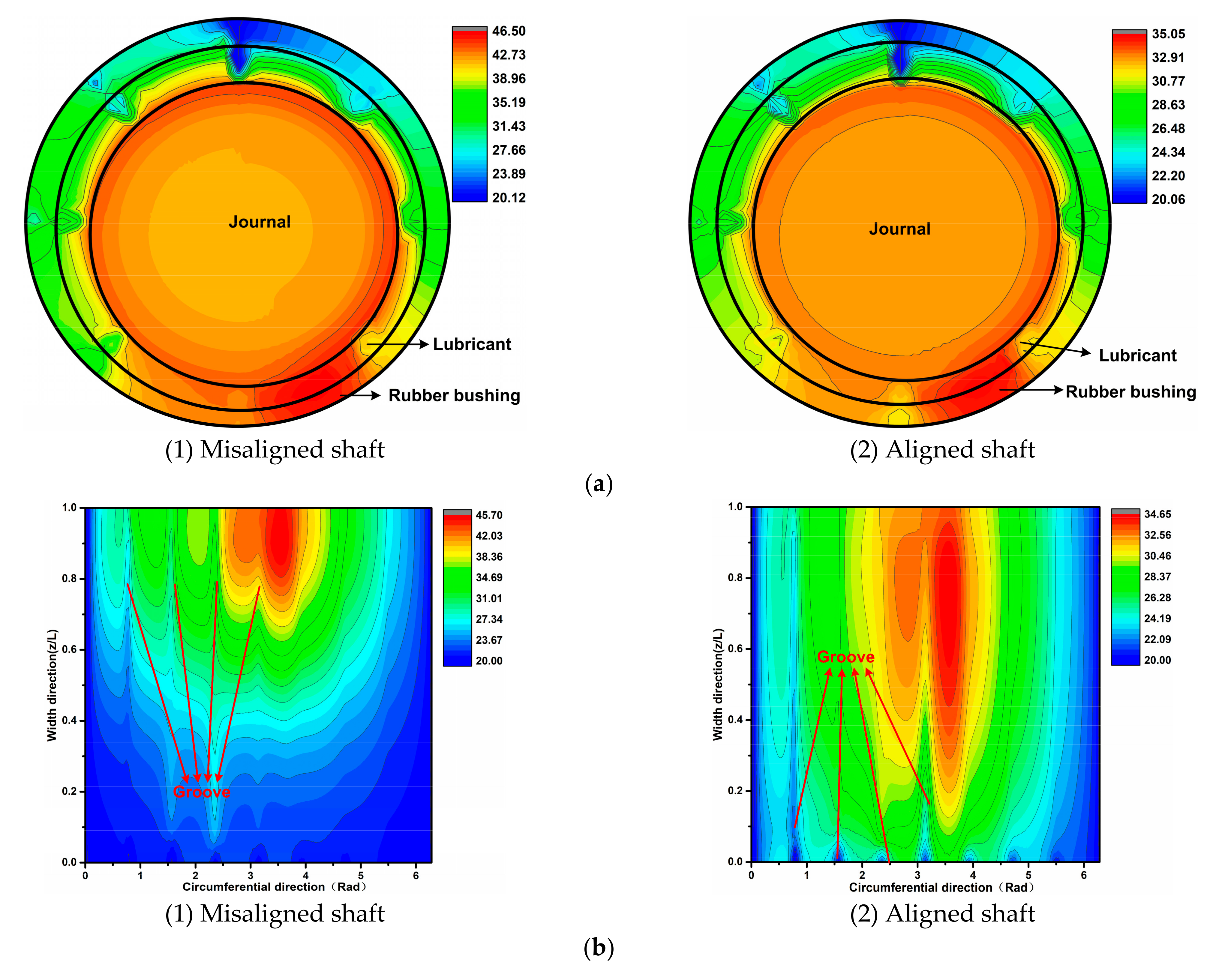
Figure 11 compares the circumferential, axial, and radial temperature distributions yielded by the deflected shaft case and the aligned shaft case. Figure 11a illustrates the circumferential temperature distribution of the JWR system at the section containing the maximum water film temperature node. As shown, the temperature of the groove region is obviously smaller than that of the pressured region because the water flow in the groove region can facilitate heat dissipation. Furthermore, the distribution trend simulated by the deflected shaft case is similar to that simulated by the aligned shaft case; however, the maximum temperature predicted by the deflected shaft case is obviously smaller than that predicted by the aligned shaft case. More specifically, the maximum temperature of the misaligned shaft case is about 11.5 °C higher than that of the aligned shaft case.
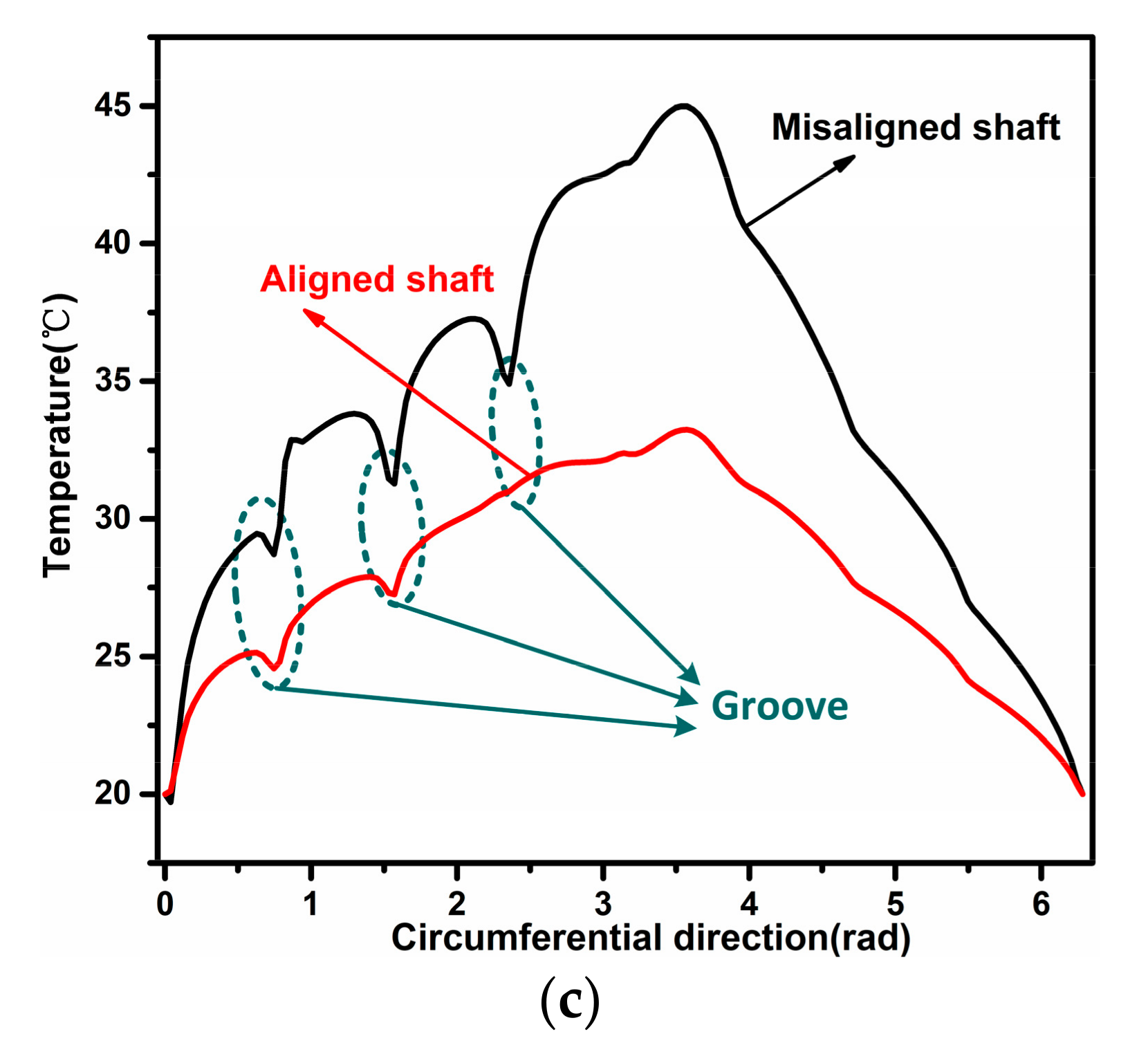
The axial temperature distribution of the water film is shown in Figure 11b, and the radial temperature distribution of the JWR system at the maximum temperature section is shown in Figure 11c. As shown in Figure 11b, compared with the aligned shaft case, the maximum temperature zone generated by the misaligned shaft case is closer to the water outlet side. The results demonstrate that inaccurate FSH predictions may be yielded if the deflection of the propeller shaft is ignored. As shown in Figure 11c, the shaft exhibits a lower temperature compared with the water film and the rubber bushing owing to the higher thermal conductivity coefficient (Table 1) compared with the other two. It is noteworthy that, as shown in Figure 11d, the temperature of the misaligned shaft case is lower than that of the aligned shaft case for z/L in the range from 0 to 0.58 and that the maximum water temperature is located nearby the water outlet for both aligned and misaligned shaft cases. These discrepant results between the two cases prove that the deformation of the propeller shaft, resulting from the propeller self-weight, the hydrodynamic force of water film, and contact force of the journal–rubber interface, cannot be neglected in the thermal analysis of WLRSBs.
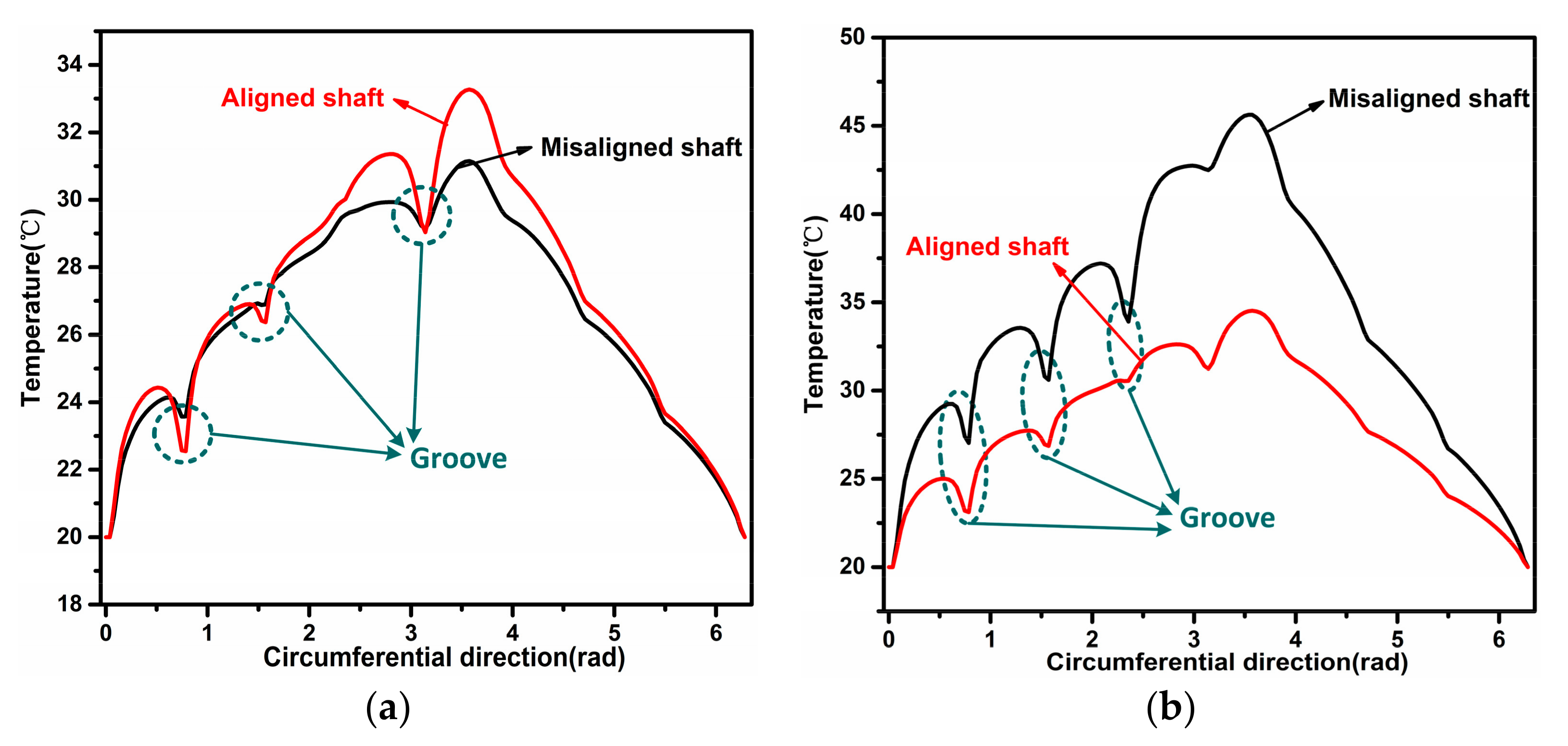
The results shown in Figure 12 are the temperature distributions in the circumferential direction for three different axial sections: the maximum temperature section, the middle section (z/L = 0.5), and the end face of the bearing (z/L = 1). As shown for the case of the z/L = 0.5 section, the maximum water film temperature of the aligned shaft case is slightly higher than that of the misaligned shaft case. However, Figure 12b,c show that for the cases of the maximum temperature section and the z/L = 1.0 section, the water film temperature yielded by the misaligned shaft case is obviously higher than that yielded by the aligned shaft case. These results indicate that the thermal performance of the WLRSB depends highly on the fluid–solid coupling effects of the outlet water side when the deflection of the shaft has been considered.

3.4. Comparisons of FSH Coupling Performance

In this section, the FSH coupling performances of the JWR system, including the contact load, maximum temperature, and maximum thermal–elastic deformation, obtained with the aligned shaft case and the misaligned shaft case under different external forces are studied comparatively. In order to make the sensitive studies clearer for readers, under various parameters, a dimensionless process for pressure (hydrodynamic and contact) and deformation (elastic and thermal) is performed in the figures of the current section. The dimensionless process of pressure and load can be expressed as:
p ¯ = p η N C R 1 2 , F ¯ = F η N C R 2
where N is the revolutions of the journal per second.
The dimensionless process of deformation can be expressed as:
δ ¯ = δ σ
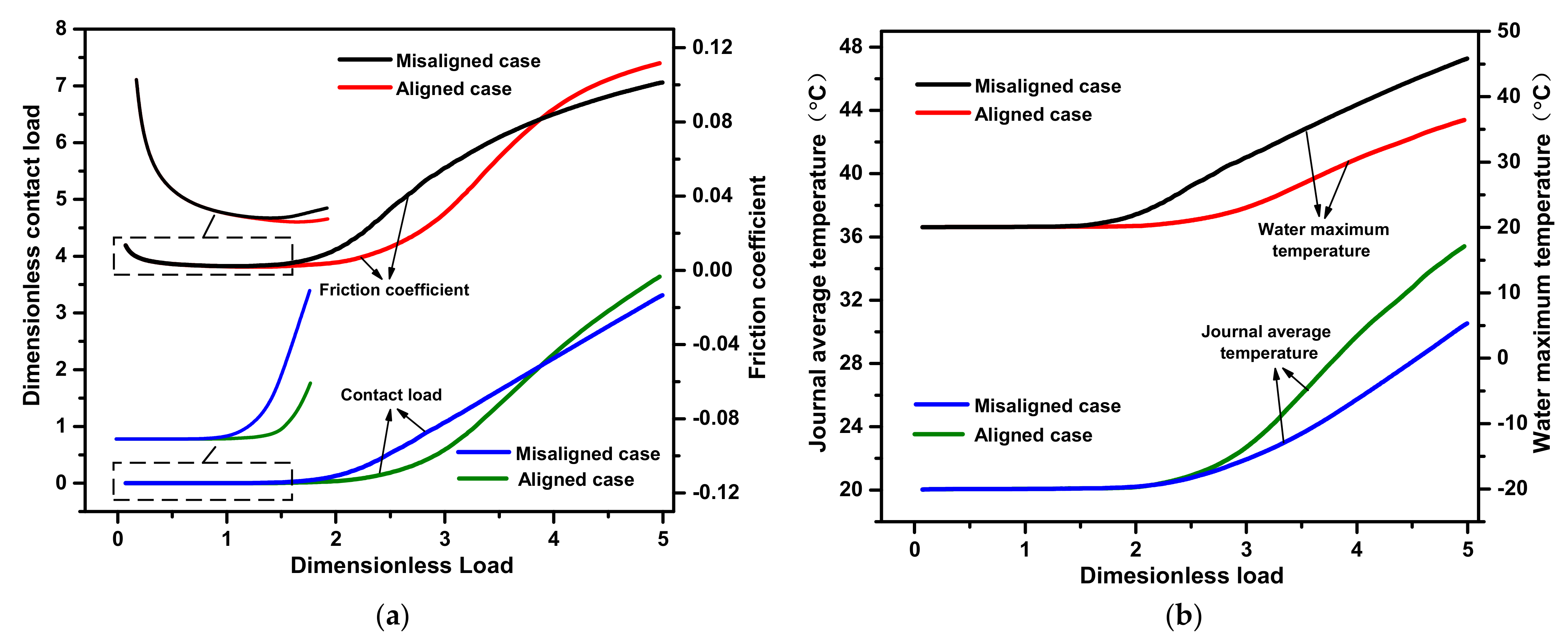
The comparisons of the contact load and the friction coefficient between the two cases are shown in Figure 13a. The contact load yielded by the misaligned shaft case was almost same as that from the aligned shaft case when the external load was less than 3 kN. However, when the external load increases from 3 to 8 kN, the contact load generated by the misaligned shaft case becomes higher than that of the aligned shaft case; the reason for this is that the deflected shaft effect is gradually enhanced with the increasing external load. Additionally, it can be found from Figure 13a that the friction coefficient for both cases decreased when the load capacity increased from 1 to 3 kN, which conforms to the elastohydrodynamic lubrication theory [4].
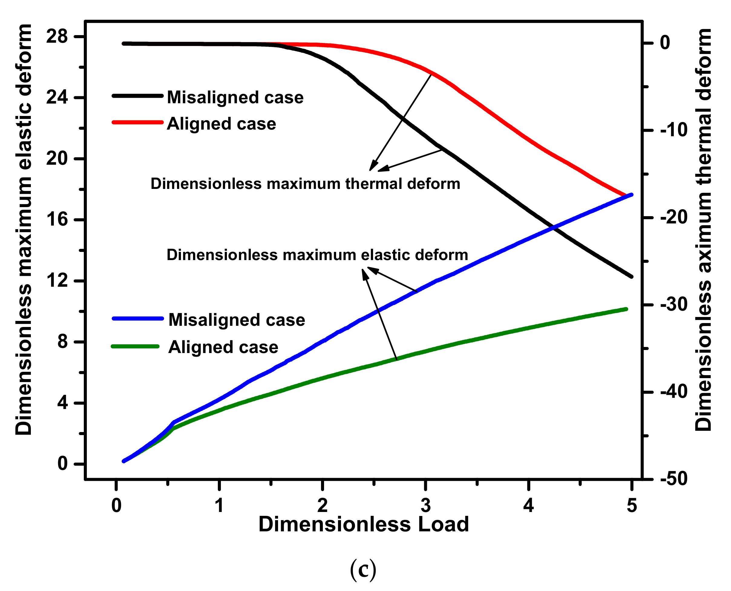
Figure 13b,c show comparisons of the maximum temperature and thermal–elastic deformation, respectively. The maximum temperatures of the misaligned shaft case and the aligned shaft case were almost the same when the external load was less than 4 kN, implying that the deflection of the propeller shaft almost does not affect the thermal performance of the WLRSB under a relatively light load condition. Meanwhile, the maximum water film temperature of the misaligned shaft case became higher than that of aligned shaft case when the load capacity was larger than 4 kN. Furthermore, Figure 14a,b can be used to explain the relationship of the maximum water film temperature between the two shaft cases. As shown in Figure 14b, for the misaligned shaft case, the contact pressure occurred mainly in the outlet water side, and its value increased sharply with the increase in load capacity. It can also be found from Figure 14b that for the load capacity in the range from 4 to 10 kN, the load capacity yielded by the misaligned shaft case was obviously larger than that yielded by the aligned shaft case (see Figure 14a). The results indicate that the misaligned shaft generates more friction heat, ΦC, compared with the aligned shaft. However, the misaligned shaft provides a smaller average temperature of journal than that of aligned shaft case when the load capacity is larger than 4 kN. This may be due to the fact that the aligned shaft yields a larger contact area under heavy load conditions. As expected, the misaligned shaft gives a larger elastic–thermal deformation than the aligned shaft, as shown in Figure 13c.
Additionally, it can be found from Figure 14a,b that “Edge contact” occurs for both shaft cases, and this phenomenon has also been observed from Litwin’s experiment (Litwin et al. [6]). Figure 14c illustrates the mechanism of the “Edge contact” shown in Figure 14a,b. As shown for the aligned shaft case, the deformation in the central area is larger than that on both sides of the WLRSB due to the “water bag” caused by hydrodynamic effects (Zhou et al. [36]), implying that the contact effect will occur on the inlet and outlet sides of the WLRSB. However, the “Edge contact” for the aligned shaft case disappears when the load capacity is larger than 4 kN, as shown in Figure 14a, which may be due to thermal expansion leading to a contact effect in the central area. As shown in Figure 14c, for the misaligned shaft case, a “water bag” may occur on the divergent side (z/L: 0–0.5) owing to this region providing a relatively large clearance to contain hydrodynamic water. The results shown in Figure 14b also indicate that for the misaligned shaft case, the “Edge contact” increased with the increase in external load.

4. Conclusions

A fluid–solid–heat coupling model for WLRSBs considering the deflection of the propeller shaft was built, and the proposed model was used to investigate the fluid–solid–heat performance of the JWR system. Based on the Euler method, a general transfer equation in polar coordinates was employed to describe the heat convection in a water film and the heat conduction in rubber bushing and a journal. The segmented mixed forces, including the hydrodynamic and contact forces, and the superposition method were bridged to evaluate the deflection of the stern shaft. Additionally, the FSH coupling performances obtained with two propeller shaft cases, i.e., aligned shaft case and misaligned shaft case, were compared systematically. The conclusions are as follows:
(1)
The temperature distribution and the load capacity obtained by the proposed model agree well with the experimental data given in the literature, thus validating that the presented model can be used to predict the FSH coupling performances of hydrodynamic bearings.
(2)
The asymmetric tribological performance distributions along the axial direction occur due to the propeller shaft deflection, including the hydrodynamic force, asperity contact, and temperature. The maximum asperity contact and temperature rise of the misaligned shaft are obviously larger than those of the aligned shaft. Furthermore, the temperature yielded by the water outlet is larger than that yielded by the water inlet for both the misaligned and aligned shaft cases.
(3)
Owing to the WLRSB having a larger length-to-diameter ratio compared with the general journal bearing, the misalignment caused by the deflection of the propeller shaft affects the FSH performance of the JWR system significantly, especially under a relatively heavy load condition. Furthermore, the aligned shaft case was found to be a proper substitute for a misaligned shaft case when the load capacity is smaller than 4 kN for the current simulation.
This study develops a comprehensive steady FSH coupling model for a water-lubricated rubber bearing operated at the stern shaft system, in which shaft deflection is caused by the self-weight of the propeller that is integrated. The present mathematical model conducts toward a guideline to help design appropriate parameters for increasing the reliability of water-lubricated rubber bearings. In addition, future works are needed to integrate rotor dynamic characteristics into the present model and to study the interaction between the FSH coupling performance and the high inertia components of a propeller in specific applications.

Author Contributions

Conceptualization, Y.H.; funding acquisition, Y.H.; methodology, T.T. and G.X.; resources, Y.H.; investigation, T.T.; format analysis, T.T.; software, G.X.; validation, H.J.; data curation, H.J.; writing—original draft preparation, T.T.; writing—review and editing, T.T. All authors have read and agreed to the published version of the manuscript.

Funding

This work was supported by the National Science Foundation of China (51605053 and 51475051) and the Fundamental Research Funds for the Central Universities Self-determined Project of the State Key (106112017CDJXY110007).

Institutional Review Board Statement

Not applicable.

Informed Consent Statement

Not applicable.

Data Availability Statement

The data presented in this study are available on request from the corresponding author.

Conflicts of Interest

The authors declare no conflict of interest.

Nomenclature

RBBearing radius, mm
LBearing width, mm
phHydrodynamic pressure, MPa
ωAngular velocity, rad/s
hLubrication gap, μm
φFlow/shear/contact factor
σSurface roughness, μm
ρWater density, kg/m3
ηWater viscosity, Pa·s
hgGroove depth, μm
δDeformation, μm
h0Average geometric gap, mm
CRadial clearance, mm
ϕAttitude angle, rad
εEccentricity ratio
eEccentricity
dShaft deflection, μm
FForce, N
MSelf-weight of propeller, kg
EElastic modulus, MPa
IInertia moment, mm4
DShaft diameter, mm
esEccentricity of end face
pcContact pressure, MPa
HBBearing hardness, Pa
βAsperity curvature radius, μm
DsAsperity density
vVelocity, m/s
GREInfluence coefficient of elastic
GRTInfluence coefficient of thermal
VVolume, mm3
AArea, mm2
αJCoefficient of thermal expansion
νΒBearing Poisson ratio
νJJournal Poisson ratio
HdDimensionless lubrication gap
βAsperity curvature, μm
δΒΕElastic deformation, μm
δΤ0Thermal deformation, μm
GBEElastic influence coefficient
GBTThermal influence coefficient
ΔΤTemperature rise, °C
TTemperature, °C
CPSpecific heat capacity, J/(kg·K)
TcTemperature of water inlet, °C
TAmbient temperature, °C
hhHeat transfer coefficient, W/m·K
RgGroove radius, mm
WgGroove width, mm
ngGroove number
ΦHeat source, J
μcBoundary friction coefficient
FfFriction force, N
kThermal conductivity, W/m·K
uLinear velocity of journal, m/s
Subscripts:
R, W, JRubber, water, journal
j, kCircumference, axial node
θ, z, rCircumference, axial, radial direction
x, yTangential, normal
sShear
h, cHydrodynamic, contact
E, TElastic, thermal
gGroove

References

  1. Roy, L.; Orndorff, J.R. Water-lubricated rubber bearings, history and new developments. Nav. Eng. J. 1985, 97, 39–52. [Google Scholar]
  2. Szeri, A.Z. Composite-film hydrodynamic bearings. Int. J. Eng. Sci. 2010, 48, 1622–1632. [Google Scholar] [CrossRef]
  3. Prakash, J.; Sinha, P. Lubrication theory for micropolar fluids and its application to a journal bearing. Int. J. Eng. Sci. 1975, 13, 217–232. [Google Scholar] [CrossRef]
  4. Hamrock, B.J.; Schmid, S.R.; Jacobson, B.O. Fundamentals of Fluid Film Lubrication; CRC Press: Boca Raton, FL, USA, 2004. [Google Scholar]
  5. Zhang, Y.; Li, X.; Dong, C. A semianalytical approach to nonlinear fluid film forces of a hydrodynamic journal bearing with two axial grooves. Appl. Math. Model. 2019, 65, 318–332. [Google Scholar] [CrossRef]
  6. Litwin, W. Influence of local bush wear on water lubricated sliding bearing load carrying capacity. Tribol. Int. 2016, 103, 352–358. [Google Scholar] [CrossRef]
  7. Lin, J. The influences of longitudinal surface roughness on sub-critical and super-critical limit cycles of short journal bearings. Appl. Math. Model. 2014, 38, 392–402. [Google Scholar] [CrossRef]
  8. He, T.; Zou, D.; Lu, X. Mixed-lubrication analysis of marine stern tube bearing considering bending deformation of stern shaft and cavitation. Tribol. Int. 2014, 73, 108–116. [Google Scholar] [CrossRef]
  9. Kraker, A.D.; Ostayen, R.A.J.; Rixen, D.J. Calculation of Stribeck curves for (water) lubricated journal bearings. Tribol. Int. 2007, 40, 459–469. [Google Scholar] [CrossRef]
  10. Chan, C.; Han, Y.; Wang, Z. Exploration on a fast EHL computing technology for analyzing journal bearings with engineered surface textures. Tribol. Trans. 2014, 57, 206–215. [Google Scholar] [CrossRef]
  11. Han, Y.; Chan, C.; Wang, Z. Effects of shaft axial motion and misalignment on the lubrication performance of journal bearings via a fast mixed EHL computing technology. Tribol. Trans. 2015, 58, 247–259. [Google Scholar] [CrossRef]
  12. Lv, F.; Rao, Z.; Na, T. Mixed-lubrication analysis of thin polymer film overplayed metallic marine stern bearing considering wall slip and journal misalignment. Tribol. Int. 2017, 109, 390–397. [Google Scholar] [CrossRef]
  13. Pu, W.; Wang, J.; Zhang, Y. A Theoretical analysis of the mixed elastohydrodynamic lubrication in elliptical contacts with an arbitrary entrainment angle. J. Tribol. Trans. ASME 2014, 136, 041505. [Google Scholar] [CrossRef]
  14. Majumdar, B.C.; Saha, A.K. Temperature distribution in oil journal bearings. Wear 1974, 28, 259–266. [Google Scholar] [CrossRef]
  15. Bouyer, J.; Fillon, M. An experimental analysis of misalignment effects on hydrodynamic plain journal bearing performances. J. Tribol. Trans. ASME 2002, 124, 313–319. [Google Scholar] [CrossRef]
  16. Pierre, I.; Bouyer, J.; Fillon, M. Thermohydrodynamic behaviour of misaligned plain journal bearings: Theoretical and experimental approaches. ASLE Trans. 2004, 47, 594–604. [Google Scholar]
  17. Mitsui, J.; Hori, Y.; Tanaka, M. An experimental investigation on the temperature distribution in circular journal bearings. J. Tribol. Trans. ASME 1986, 53, 621–627. [Google Scholar] [CrossRef]
  18. Fitzgerald, M.K.; Neal, B. Temperature distributions and heat transfer in journal bearings. J. Tribol. Trans. ASME 1992, 114, 122–130. [Google Scholar] [CrossRef]
  19. Wang, Y.; Zhang, C.; Wang, Q. A mixed-TEHD analysis and experiment of journal bearings under severe operating conditions. Tribol. Int. 2002, 35, 395–407. [Google Scholar] [CrossRef]
  20. Yadav, J.S.; Kapur, V.K. On the viscosity variation with temperature and pressure in thrust bearing. Int. J. Eng. Sci. 1981, 19, 269–277. [Google Scholar] [CrossRef]
  21. Sahu, M.; Sarangi, M.; Majumdar, B.C. Thermohydrodynamic analysis of herringbone-grooved journal bearings. Tribol. Int. 2006, 39, 1395–1404. [Google Scholar] [CrossRef]
  22. Sun, J.; Deng, M.; Fu, Y. Thermohydrodynamic lubrication analysis of misaligned plain journal bearing with rough surface. J. Tribol. Trans. ASME 2010, 132, 011704–011708. [Google Scholar] [CrossRef]
  23. Mishra, P.C. Mathematical modeling of stability in rough elliptic bore misaligned journal bearing considering thermal and non-Newtonian effects. Appl. Math. Model. 2013, 37, 5896–5912. [Google Scholar] [CrossRef]
  24. Lin, X.; Jiang, S.; Zhang, C. Thermohydrodynamic analysis of high speed water-lubricated spiral groove thrust bearing considering effects of cavitation, inertia and turbulence. Tribol. Int. 2018, 119, 645–658. [Google Scholar] [CrossRef]
  25. Hoon, K.S.; Won, L.S.; Sangmok, H. Numerical investigation of thermal characteristics of spray cooling with minimum quantity lubrication in milling process. Appl. Math. Model. 2018, 65, 137–147. [Google Scholar]
  26. Pu, W.; Wang, J.; Zhu, D. Friction and flash temperature prediction of mixed lubrication in elliptical contacts with arbitrary velocity vector. Tribol. Int. 1999, 99, 38–46. [Google Scholar] [CrossRef]
  27. Li, Y.; Ji, Z.; Yang, L. Thermal-fluid-structure coupling analysis for valve plate friction pair of axial piston pump in electrohydrostatic actuator (EHA) of aircraft. Appl. Math. Model. 2017, 47, 839–858. [Google Scholar] [CrossRef]
  28. Feng, H.; Jiang, S.; Ji, A. Investigations of the static and dynamic characteristics of water-lubricated hydrodynamic journal bearing considering turbulent, thermohydrodynamic and misaligned effects. Tribol. Int. 2019, 130, 245–260. [Google Scholar] [CrossRef]
  29. Wodtke, M.; Litwin, W. Water-lubricated stern tube bearing-experimental and theoretical investigations of thermal effects. Tribol. Int. 2021, 153, 106608. [Google Scholar] [CrossRef]
  30. Litwin, W.; Olszewski, A.; Wodtke, M. Influence of shaft misalignment on water lubricated turbine sliding bearings with various bush modules of elasticity. Key Eng. Mater. 2011, 490, 128–134. [Google Scholar] [CrossRef]
  31. Mallya, R.; Shenoy, S.B.; Pai, R. Steady state characteristics of misaligned multiple axial groove water-lubricated journal bearing. J. Eng. Tribol. 2014, 229, 712–722. [Google Scholar] [CrossRef]
  32. Wu, C.; Zheng, L. An average reynolds equation for partial film lubrication with a contact factor. J. Tribol. Trans. ASME 1989, 111, 83–90. [Google Scholar] [CrossRef]
  33. Kogut, L.; Etsion, I. Elastic-plastic contact analysis of a sphere and a rigid flat. J. Appl. Mech. 2002, 69, 657–662. [Google Scholar] [CrossRef] [Green Version]
  34. Xiang, G.; Han, Y.; He, T. Wear and fluid-solid-thermal transient coupled model for journal bearings. Appl. Math. Model. 2020, 85, 19–45. [Google Scholar] [CrossRef]
  35. Hirs, G.G. The load capacity and stability characteristics of hydrodynamic grooved journal bearings. ASLE Trans. 1965, 8, 296–305. [Google Scholar] [CrossRef]
  36. Zhou, G.; Wang, J.; Han, Y. An experimental study on film pressure circumferential distribution of water-lubricated rubber bearings with multiple grooves. ASLE Trans. 2016, 60, 385–391. [Google Scholar] [CrossRef]
Figure 1. Assembly and operating mechanism for a water-lubricated rubber stern bearing (WLRSB).
Applsci 11 01170 g001
Figure 2. Schematic of water-lubricated rubber stern bearing.
Applsci 11 01170 g002
Figure 3. Schematic for the calculation of the deflection of the propeller shaft.
Applsci 11 01170 g003
Figure 4. Meshed journal, water film, and rubber bushing (JWR) system in polar coordinates.
Applsci 11 01170 g004
Figure 5. Boundary conditions for (a) elastic deformation and (b) the thermal analysis.
Applsci 11 01170 g005
Figure 6. Flow chart for the numerical simulation process of the fluid–solid–heat (FSH) performance of the JWR system.
Applsci 11 01170 g006
Figure 7. Temperature analysis results in comparison with the experiment data from Wang et al. [19] under different working conditions (6672 N and 1000 rpm).
Applsci 11 01170 g007
Figure 8. Structure temperature analysis results in comparison with the experimental data given in Mitsui et al. [17]: (a) results obtained by the proposed model; (b) the experimental results.
Applsci 11 01170 g008
Figure 9. Comparison of simulated load capacity with experimental data of Hirs et al. [35].
Applsci 11 01170 g009
Figure 10. Distribution of deformations and pressure when deflection of the propeller shaft is considered: (a) water film pressure; (b) contact pressure; (c) elastic deformation; (d) thermal deformation.
Applsci 11 01170 g010
Figure 11. Comparisons of the thermal distribution in the circumferential section, axial direction, and radial section obtained with a misaligned shaft and an aligned shaft: (ac) are the temperature distribution in the circumferential section, axial section, and radial section, respectively: (d) is the temperature distribution at the maximum water temperature section in the axial direction.
Applsci 11 01170 g011aApplsci 11 01170 g011b
Figure 12. Comparisons of temperature distribution of the water film obtained with a misaligned shaft case and an aligned shaft case under different axial sections of the WLRSB: (a) at z/L = 0.5; (b) at maximum temperature; (c) at z/L = 1.
Applsci 11 01170 g012aApplsci 11 01170 g012b
Figure 13. Comparisons of the FSH performance of the JWR system obtained with two cases of shaft, i.e., aligned shaft case and misaligned shaft case: (a) contact load and friction coefficient; (b) average temperature of journal and maximum temperature of water; (c) elastic and thermal deformation.
Applsci 11 01170 g013aApplsci 11 01170 g013b
Figure 14. Distributions of contact pressure in the axial section obtained with the aligned shaft case and the misaligned shaft case, respectively: (a) water film pressure; (b) contact pressure; (c) edge effect of the aligned shaft and the misaligned shaft case.
Applsci 11 01170 g014
Table 1. The basic parameters of the proposed model.
ParameterValueParameterValue
Inner radius/R145 mmExternal force/M10 kN
Outer radius/R250 mmBearing densityR1500 kg/m3
Clearance/C0.15 mmRubber thermal conductivities/kR0.288 W/(m·K)
Bearing width/L160 mmRubber specific heat/CPR1700 J/(kg·K)
Groove radius/Rg2.5 mmRubber thermal expansion/TR121 µm/(m·K)
Groove width/Wg6 mmWater viscosity8.944 × 10−4 Pa·s
Groove number/ng8Water densityW1000 kg/m3
Journal elastic modulus/EJ210 GPaWater thermal conductivities/kW0.61 W/(m·K)
Journal Poisson ratioJ0.3Water specific heat/CPW4200 J/(kg·K)
Journal densityJ7800 kg/m3Heat transfer coefficient/hh80 W(m2·K)
Journal thermal conductivities/kJ50 W/(m·K)Inlet temperature/Tc20 °C
Journal specific heat/CPJ460 J/(m·K)Ambient temperature/T20 °C
Journal thermal expansion/TJ11.9 µm/(m·K)Friction coefficientC0.15
Bearing elastic modulus/ER7.85 × 108 PaJournal roughnessJ0.5 µm
Bearing Poisson ratioR0.47Rubber roughnessR0.6 µm
Bearing hardness/HB5 × 107 Pa
Publisher’s Note: MDPI stays neutral with regard to jurisdictional claims in published maps and institutional affiliations.