Article

Piezoelectric Energy Harvesting for Flapping Wing Micro Air Vehicle and Flapping Wing Sensing Based on Flexible Polyvinylidene Fluoride

Mechanical Materials Hall702, School of Mechanical and Aerospace Engineering, Jilin University, Changchun 130022, China
*
Author to whom correspondence should be addressed.
Appl. Sci. 2021, 11(3), 1166; https://doi.org/10.3390/app11031166
Submission received: 9 December 2020 / Revised: 7 January 2021 / Accepted: 11 January 2021 / Published: 27 January 2021
(This article belongs to the Section Energy Science and Technology)

Abstract

:
The flapping wing micro air vehicle (FWMAV) has been attracting lots of interest since the 1990s and is one of the research hotspots in microminiaturization design. However, along with the miniaturization of FWMAV development, flight endurance becomes the bottleneck that significantly impedes the rapid development for these aircrafts because of the critical limit in energy supply due to the limited overall size and weight. In this paper, energy recovery technology was developed for FWMAV with the new type polyvinylidene fluoride (PVDF) piezoelectric wing which could generate the electric potential energy caused by the wing deformation due to the characteristics of the PVDF material. A single crank double rocker mechanism flapping platform was designed to test the deformation energy collection effect and aerodynamic lift. The PVDF wing surface was divided into 16 grid areas to be measured respectively. The lift, output voltage and output power variations for the different flapping frequency was successfully obtained in tests. By analyzing test data, if could be found that the output power could reflect the flutter condition without equipping other sensors and adding extra weight to the aircraft. Moreover, when the flapping frequency was accelerated to 12 Hz, the output power and root mean square (RMS) voltage could increase to 21 μW and 6 V respectively, which is enough to power micro electronic devices such as LED lights.

1. Introduction

Flapping-wing micro aerial vehicles (FWMAVs) have many unique advantages compared to fixed-wing and rotary-wing MAVs, and one of the most important of these is having the integrated functions of hovering, lifting, and propulsion at a low Reynolds number environment with less energy for a long-time flight [1,2,3]. As result, FWMAVs have attracted a lot of attention from research institutions and companies due to their brilliant application prospects in defense and civilian fields [1,2].
Lots of flapping wing vehicles have been designed, characterized and modeled inspired by bats, insects and birds [4,5,6,7,8,9]. The flying endurance of these flapping wing vehicles has been continuously growing from 8 s to several minutes, but the traditional way that improves the battery performance in its capacity and energy density to increase aircrafts’ flying time is almost reaching a bottleneck. The flying performance of a flapping wing aircraft is affected by every component and every parameter. Adjustment of the battery may not bring obvious improvement in flying endurance, and may even impede the development of flapping wing vehicle performance because of the weight limit for the energy systems, that cannot be incorporated into the aircraft very well [10,11].
There have been many attempts to extend the flight time of unmanned aerial vehicles (UAVs) by the way of collecting energy, including solar and vibration energy [12,13,14,15]. With attached solar cells on the wing surface of an aircraft, the operational time obtained a maximum 18.7% increase. Normally, as the solar panels on aircraft wing surface increased, the energy would be more collected with the solar cell wing [16,17,18], which meant the potential of photovoltaic devices to harvest energy depends on the size of wing. Additionally, the illumination intensity would also have a large effect on energy collection and the solar panels could only harvest energy when exposed to light. For flapping wing micro air vehicles, solar panels were not appropriate for attachment on the flapping wing due to the aerodynamic requirement for the wing flexibility. Not to mention the rigid, heavy traditional solar panels, the thin film solar cell technology also had adversely effect on wing kinematics when applied on the wing surface [19,20]. However, the volumetric energy harvested by the piezoelectric patches normally was orders of magnitude less than that of the solar panels. In summary, piezoelectric technology harvesting on FWMAV had more advantages than photovoltaic technology.
Energy harvesting with piezoelectric materials has received more and more attentions in research communities throughout the past decade [21,22,23,24,25,26]. Many studies have investigated the feasibility of polyvinylidene fluoride (PVDF) material for microelectronics applications, such as the PVDF glove, the self-powered insole for human motion recognition, as well as the piezoelectric wearable sensors for body motion energy harvesting [21,22,23,24]. However, there are seldom relevant studies about the application of piezoelectric material on flapping-wing MAV. Researchers from Tamkang University proposed that a PVDF wing could modify the aerodynamic forces of a micro aerial vehicle. By comparing two kinds of data obtained in the experiment, there was a phase delay between the signal and load-cell signal. The research demonstrated that the PVDF wing has the promising capability to monitor aerodynamic information of flapping [25,26]. In this paper, we aimed to investigate further applications of PVDF material for the FWMAVs. The feasibility of energy harvesting and wing deformation sensing without increasing extra load on aircrafts was developed for FWMAVs with the new type PVDF piezoelectric wing which could generate the electric potential energy caused by the wing deformation due to the characteristics of the PVDF material. A single crank double rocker mechanism flapping platform and aerodynamic force measuring system was designed to test the relevant relationship between piezoelectric voltage and aerodynamic lift.

2. Modeling and Principle

Piezoelectric materials have been widely used in many key technology fields, including microelectronics, signal processing, sensors and actuators. Among all piezoelectric materials, PVDF material can be fabricated in desired shapes of thin film easily and it is very suitable for replacing traditional macromolecule polymer film material considering its characteristics of wide frequency range, great sensitivity of power conversion and high strength of mechanical properties.
When a piezoelectric material is mechanically deformed, electrical charges are induced on its surfaces according to the following equation:
D = d T + ε
where D is the electrical displacement, d is the piezoelectric coefficient, T is the stress, is the dielectric constant of the piezoelectric material, and ε is the electric field intensity. Regarding PVDF film as an airfoil for sensing aerodynamic force, we get the charge density D i ( i = x , y , z ) by the following piezoelectric transformation relationship:
[ D x D y D z ] = [ 0 0 0 0 d 15 0 0 0 0 d 24 0 0 d 31 d 32 d 33 0 0 0 ] × [ σ x σ y σ z τ x y τ y z τ z x ] T
The piezoelectric constant d 15 and d 24 are zero respectively, and other d i j of PVDF film are shown in the following equation.
{ d 31 = 17 , d 32 = 5 ~ 6 , d 33 = 21 , p C / N p C / N p C / N
The mathematical model for resultant force generated by wing is described as follows. We assume that there is a pressure difference distribution Δ p ( x , y , z ) between the upper and the lower sides of the flapping wing. Resultant force F is calculated by taking the surface integral of ∆p over the wing surface area S:
F = S Δ p ( x , y , z ) d A
When the pressure difference Δ p caused by the interaction of wings and air flow acts on the PVDF film, just like the case of giving a force on a shell or a plate, the PVDF film becomes deformed and stretched. We assume that the plane-stress distribution on the flapping wing as σ x ( x , y , z ) and σ y ( x , y , z ) which are related to Δ p ( x , y , z ) by the following linear relationship:
Δ p ( x , y , z ) = k x ( x , y , z ) σ x ( x , y , z ) = k y ( x , y , z ) σ y ( x , y , z )
where k x and k y are stiffness functions assumed by the authors. Due to the plane-stress problem of the flapping wing, σ z can be neglected ( σ z = 0 ), The charge density along the Z-direction therefore can be derived as:
D z ( x , y , z ) = d 31 σ x ( x , y , z ) + d 32 σ y ( x , y , z )
Combining Equations (5) and (6), the total charge Q in terms of the pressure difference Δ p and the stiffness function k as follows.
Q = S D z ( x , y , z ) d A = S Δ p ( x , y , z ) [ d 31 k x ( x , y , z ) + d 32 k y ( x , y , z ) ] d A
Because the stiff function k x and k y are not uniform over the wing skin area S, the force F in Equation (4) cannot be directly separated from Equation (7). We temporarily and equivalently replace the bracket in Equation (7) with d * , and obtain the following expression:
Q = d * F
In Equation (8), the total charge Q can be also expressed by a voltage U across the PVDF capacitor C by the relationship:
Q = C U
Combining Equations (8) and (9), the force can be determined linearly with the voltage U.
F = Q d * = ( C d * ) × U
The simplified model described by Equation (10) gives us a guideline in principle that the information can be obtained electrically from the voltage given by the PVDF piezoelectric film. According to Hooke’s law, stress and strain are directly proportional.
T = E Δ l l
where E is Young’s modulus, l and Δ l are the initial and differential lengths of the piezoelectric material, respectively. According to the piezoelectric effect, the electric charge quantity Q is written below:
Q = d E S Δ l l
Ignored the effect of the electric field on the strain, and capacitance of the piezoelectric layer C is defined as:
C = ζ S 4 π a h
where ζ , a and h are dielectric constant, electrostatic force constant, and thickness of PVDF film. Voltage generated by the piezoelectric films can be expressed as follows:
U = 4 π a h ζ d E Δ l l
In addition, the generation energy from Equation (12) can be written as:
W = 1 2 C U 2 = 2 π h a S ζ d 2 E 2 ( Δ l l ) 2
The simple model described in Equation (10) shows that the aerodynamic force can be measured by the voltage signal generated by the PVDF film. Additionally, the deformation information of PVDF film is also included in the electrical signal. Equations (14) and (15) show the guideline that a fast deformation of a piezoelectric material can increase output current and voltage, which means flapping frequency is of vital importance to the piezoelectric properties of PVDF wing. In addition, the large strain could generate large electrical energy and high output power, which is the time derivative of the energy W given in Equation (15). As a result, we could get sufficient details about the flapping PVDF wing with appropriate data process methods.

3. Experiment

3.1. Flapping Wing Test Platform

To explore the effect of piezoelectric energy harvesting and wing deformation sensing with flexible PVDF wing under the dynamic conditions, a single crank double rocker mechanism platform was designed and built as shown in Figure 1, based on the principle of simplicity and motion symmetry, consisting of a gear-transmission set, a four-bar linkage and DC servo motor (Maxon RE13). The gear set and motor are arranged on the double acrylic board frame, which was fabricated by CNC machine. The crank arm driven by the gear set and motor, can achieve a full revolution and power the linkage and wings.
To produce appropriate aerodynamic lift force, ornithopters generally rely on large flapping amplitude by compliant mechanism at a lower flapping frequency. In this paper, the flapping angle of the platform is about 60 degrees and the flapping frequency range could vary from 3 Hz to 17 Hz, which is suitable test flapping models [27]. There is also one thing that should not be overlooked that a small mechanical phase lag unavoidably exists in the platform due to the asymmetric four-bar linkage structure.

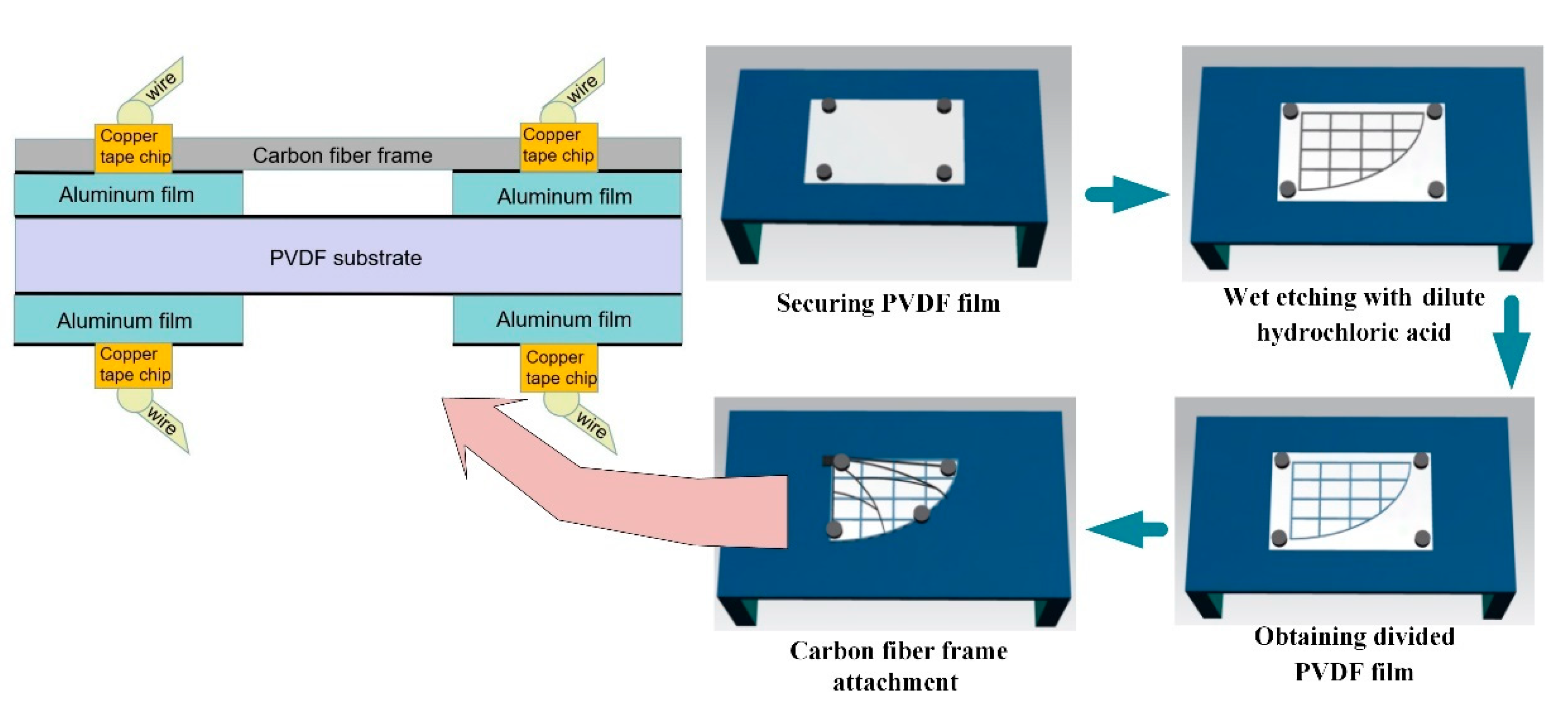
3.2. PVDF Wing Fabrication

Inspired by the vein layout and membrane shape of fruit flies [28,29], PVDF flapping wings were designed and fabricated. Besides the characteristics of being light and strong, the wing airfoil should be capable of withstanding high flapping frequency without breaking. The wings in this paper were composed of carbon fiber frame vein and PVDF membrane as shown in Figure 2.
The PVDF membrane (KXP03, Jinzhoukexin company, Jinzhou, China) has a film thickness of 30 μm, whose both sides are coated with 5 nm thick aluminum film by vapor deposition process. It means that the potential of the whole PVDF film surface remains the same value. As a result, when cut the PVDF film into desired shape, we should pay more attention to the cutting burr on the edge to avoid upper and lower surfaces connecting in electrical test. Due to the 2D plane structure of main spar and ribs of the wing frame, and the machining characteristic of carbon fiber material, we fabricated the 0.5 mm thick carbon fiber wing frame with a computer numerical control CNC machine.
In order to further investigate the deformation and piezoelectric output of different PVDF wing areas, we need to divide the whole PVDF film into many parts, which could be viewed as many electrodes respectively in electrical measuring test. As a result, the wet etching aluminum electrode processes were developed considering the excellent corrosion resistance of PVDF material. The electrode division process shown in Figure 3 consisted of the following steps:
(a).
A sheet of PVDF film was secured to a stable worktable with the use of magnets.
(b).
The PVDF film surface was marked with water according to the designed grid line layout, then used a fine brush with dilute hydrochloric acid carefully draw the grid line trace.
(c).
After a minute when the reaction finished, the PVDF film was sprinkled with sodium carbonate powder to neutralize extra dilute hydrochloric acid. Next, the PVDF film was washed with plasma water.
(d).
Lastly, the carbon fiber frame was attached to the PVDF film carefully with electrical insulation glue.
The other side of the PVDF film was divided into the same regular grid area as the electrodes by the wet etching processes mentioned above.
Bonding every divided PVDF area to a wire was a difficult task. The PVDF material got the heat distortion temperature of 112~145 degrees Celsius, so the PVDF film did not have good heat-resistance. It meant that the wire cannot be welded directly onto the PVDF film surface with an electric iron, because electric iron welding may break through the wing membranes, creating a short-circuit or increasing regional stiffness. It is well known that the flexible deformation of the wing is critical for the generation of aerodynamic forces, which requires a connection way between the wires and PVDF divided areas that has less effect on the whole flexibility without great damage to the membrane.
We proposed that 0.06 mm thick double-side conductive copper tape (3M Company, Dalian, China) would be appropriate as the middle layer between the PVDF film and wires. Along the line of thinking mentioned above, we cut the conductive copper tape into 3~4 mm2 pieces, then welded 0.1 mm-diameter enameled wire onto the copper tape chip surface. After that, put the sticky side of these tape chips onto the divided PVDF areas with appropriate pressure. Lastly, every weld wire was tested with digital multimeter to make sure of the good conductivity. The 124 mm PVDF wing is shown in Figure 2, and Figure 3 weighed 1.9 g and had the maximum chord length of 80 mm.

3.3. Measuring Device

Since existing models require immense computational power and resource to calculate aerodynamic loads acting on the compliant wing surface, direct measurement of these loads during flapping cycles was selected as the method for gaining insight into the effects of wing design parameters on the wing mechanics.
In this paper, the whole experiment system shown in Figure 4 consisted of the vibration isolation platform, force measuring device, flapping platform, charge amplifier (Type 5081, KISTLER), load sensors (Type 9211B, KISTLER), PMAC, oscilloscope and computer, with Figure 5 showing the connections between every part. The force measuring device with two load sensors to measure the aerodynamic lift and thrust simultaneously was developed based on flexure hinge structure shown in Figure 6. The load sensors were responsible for the force measurement of horizontal and vertical forces directly, which could be viewed as total thrust and lift respectively. It has the maximum error 0.2% of the full-scale signal due to nonlinearity or hysteresis. The electric potential signal generated by PVDF wings was measured by the oscilloscope. The aerodynamic force and electrical signal were obtained at the flapping frequency of 5~20 Hz and Figure 4 showed the whole devices of the experiment.

4. Test and Analysis

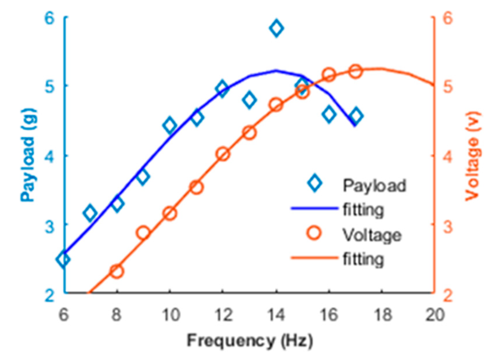
4.1. Lift and Voltage

In the test the flapping the aircraft adopted PVDF and macromolecule polymer film as left and right wing respectively. Instead of lithium battery, DC voltage stabilizer was used to power the aircraft in case of instability induced by the consumption of battery electricity. A series of parametric tests were conducted for a range of flapping frequencies while keeping flapping wing platform driven motor input voltage constant in windless condition. The aerodynamic signal and voltage data were captured by load-cell and oscilloscope respectively, stored on the computer. When the aircraft was excited, the load sensors were activated from idle condition to record the real-time value of the measured forces for about 60 continuous cycles.
Figure 7 showed the variation of lift and voltage versus time at the 10 Hz flapping frequency based on a whole PVDF film without wet etching process. It appeared that the waveforms of these two kinds of data were very similar in waveform except for the amplitude size. It should be mentioned that except for the low flapping frequency phase, the lift and voltage curves always have good similarity in waveform. As a result, it provided the primary hypothesis that these two kinds of signal have certain relationship, then more experiments about PVDF wing were conducted.
Combining the voltage data in Figure 7 and the Equation (16), we could get the root mean square (RMS) output voltage. The relationship of the mean lift force and RMS output voltage versus flapping frequency are shown in Figure 8. It can be seen from the fitting curves that the values of lift and voltage are proportional to the flapping frequency as the flapping frequency is below 14 Hz. Once flapping frequency exceeded the relative peak value, the payload and voltage value turned to a decreasing trend. This is because PVDF wing could not have enough time to finish the whole flapping motion in one cycle, which meant the PVDF wing was not able to accomplish the desired flapping amplitude. Due to complex deformation condition, it had a disturbance or counteraction phenomenon when the output signal had a different phase gradient of different bending the PVDF wing areas. These two factors collectively affected the increase trend of output voltage in high flapping frequency phase. As a result, it was important to choose an appropriate flapping frequency for PVDF wing application:
U R M S = 1 N T 0 N T U 2 ( t ) d t
According to the varying trend of lift force and RMS voltage data in Figure 8, we could see that the voltage line lagged the payload line about 3 Hz and these two curves were very similar to each other in waveform without considering the phase shift between them. As a result, the functions over time of the force or voltage had a specific relationship and could be expressed by each other. It offered an opportunity to obtain the aerodynamic lift by measuring piezoelectric voltage signal for flapping aircrafts.

4.2. Output Power

To obtain the maximum value of the power output, a series of different resistances were tested as load resistance paralleled with PVDF film under different flapping frequencies. According to Equations (16) and (17), the output RMS power values were studied. The fitting curves of output RMS power variations for different load resistance under the condition of 5, 7.5, 10, 12.5 and 15 Hz flapping frequency were plotted on Figure 9. In order to obtain more details between output power and load resistance, the output power curves adopted cubic polynomial fitting. It showed that there were no obvious changes for output power in low flapping frequency phase and the RMS output power increased rapidly with the frequency increase without considering resistance. The effect of flapping frequency on output power was much greater than that of load resistance. As a result, it was of vital importance to enhance flapping frequency for output power improvement. As seen in Figure 9, the maximum RMS output power could be up to 21 μW with 15 Hz flapping frequency and 0.4 MΩ corresponding matching load resistance, which was sufficient to drive certain miniature electronic components, such as LED lights.
P R M S = U R M S 2 R l o a d
As seen in Figure 10, when the frequency was lower than 12.5 Hz, the open-circuit voltage and the output power versus frequency were linear and quadratic respectively. Equations (14) and (15) were verified by the test from another point of view. When the flapping frequency exceeded 12.5 Hz, the growth rate for both voltage and power was declining, it was due to the reason that the deformation amplitude differed at different frequencies. When the flapping frequency was in a high phase, the PVDF wing could not finish the maximum deformation in chord and wingspan direction in one flapping cycle, causing electric data to be adversely affected.

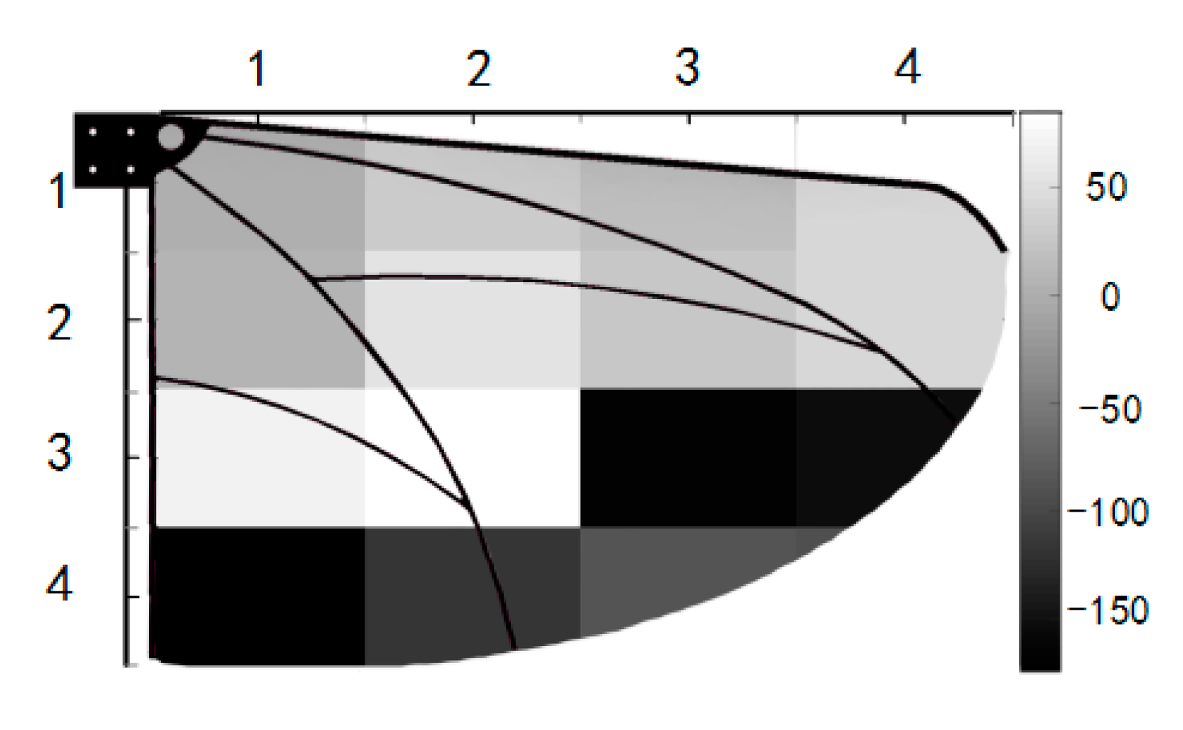
4.3. Segmentation Test

In order to explore more details about the PVDF characteristics applied in flapping wing, the PVDF wing skin was divided into 4 rows and 4 columns to study the relationship of flapping deformation and electric data. These divided areas were named as Vij (I = 1~4, j = 1~4) respectively and 16 areas of the PVDF film were obtained totally. Given the size of small area of V44, V44 was merged into V43 part. There was also one minor thing that should be considered, that all grid line area was measured into relative parts, considering area factors. In the test, we took 10 Hz as the test frequency and conducted low-pass filtering on the obtained signal. To make the image more clearly shown in one picture, the real time voltage data was processed in advance. The voltage value of the first row of PVDF divided areas was reduced to half, the voltage value of third and fourth row multiply 2 and 3 respectively, the processing result of these areas was shown in Figure 11. It was obvious that the real time voltage signal of all these grid blocks displayed trigonometric function waveform and the first-row grid blocks had the maximum voltage value compared with others in column direction.
According to the Equation U = 4 π h Q / ϵ S , we could know that the area size would have effect on the value of output voltage and power. In order to investigate more piezoelectric characteristics of different PVDF areas, the area size factor should be eliminated. So, the area normalization method was proposed and V11 was set as the standard block area, then others compared with the reference grid block getting their area normalization scale factors. The area normalization scale factors for each grid block can be found in Table 1.
Combining the factors in Table 1 and the real voltage of each part in Figure 11, we could get the modified RMS output voltage value and piezoelectric level of each block shown in Table 2 and Figure 12 respectively.
By analyzing the data obtained from the piezoelectric experiments, we found that the piezoelectric voltage of wing-root area far exceeds the voltage of other parts and whole PVDF film wing shown in Figure 7. It was not hard to deduce that wing-root area also has the largest amplitude of deformation with the fastest variation rate at the same time. Through further analysis, it was found that both of real time voltage amplitude and RMS voltage decline numerically from the wing-root area to the edge area. Along the wingspan direction, the amplitude of deformation of the PVDF wing showed the similar law that the curving degree or deformation curvature decreased gradually from wing root to wingtip verified by the camera. Because of the comprehensive effect of wing inertia and air-resistance, the area near the wing root apparently bent more easily and rapidly. According to the Equations (14) and (15), wing root area had the largest output voltage and power which was verified in Figure 11 and Figure 12. In conclusion, the RMS voltage level could reflect the curving degree of PVDF wing directly in situ way, which provided the feasibility to detect the flutter condition without equipping other sensors and adding extra weight.
Expect for the amplitude of voltage, the phase was also very critical for signal analysis. With the help of MATLAB, the primary data was processed quickly and accurately. Firstly, the primary voltage data was filtered by the Butterworth low-pass filter, then the voltage phase difference was obtained by using Hilbert method. We took the V11 area voltage signal phase as zero, then the else voltage data phase difference would be obtained compared with the standard, and set the advanced phase as positive part and the lagged phase as negative part shown in Figure 13. There were phase lags in both wingspan direction and chord direction and the edge areas had the maximum phase lag compared with the phase of V11 which almost could be up to negative 180 degrees. Combining the amplitude and phase lag of output voltage, it was possible to obtain the flapping state of every gird area on the PVDF wing.

4.4. Energy Havesting

The working principle of the PVDF piezoelectric wing was to convert the mechanical energy generated by the reciprocating bending vibration into electric energy during wing flapping process. The energy harvesting circuit used in this paper was the classic energy harvesting circuit shown in Figure 14. It is divided into three basic parts: full-bridge rectification, voltage regulation, and filtering.
The AC signal output by the piezoelectric element was converted into a DC signal (AC–DC conversion) after full-bridge rectification, and the capacitor Ce acts as a filter and a voltage regulator. In order to obtain a relatively ideal DC voltage, a filter circuit composed of a capacitor having an energy storage function is required to filter the pulsating component in the output voltage of the rectifier circuit to obtain a DC voltage.
In order to verify the power generation effect of PVDF piezoelectric wing, this paper used a rectifier bridge to form an AC–DC conversion circuit, and used a 47 μF filter capacitor to stabilize the voltage. The experimental device in Figure 15 successfully illuminated the letter ‘JLU’ consisting of 14 red LED lights at the flutter frequency of 15 Hz shown in Figure 16. It offered the feasibility to drive micro electrical components without extra energy consumption of the energy source, which could extend the flying endurance.

5. Conclusions

This paper presents a new kind flapping wing based on piezoelectric PVDF film, which processes the promising capability to measure aerodynamic force and monitor flapping wing attitude without increasing extra load on aircraft. In the experiment, the signals of the PVDF wing and load cell show high similarity in their waveforms. It has the feasibility to deduce the lift by getting the piezoelectric voltage signal without other sensors. Both signals of voltage and lift increase with the flapping frequency increase, but the payload and voltage value would have a decreasing trend when the frequency exceeds the relative peak value. This is because the PVDF wing could not have enough time to finish the whole flapping motion in one cycle, which means the PVDF wing is not able to accomplish the desired flapping amplitude. Due to complex deformation conditions, there are disturbances or counteraction phenomena when the output signal has different phase gradients of different bending PVDF wing areas. By the wet etching process, the PVDF wing is divided into 16 blocks and we get more details between wing deformation and piezoelectric signal. Obviously, due to the largest amplitude of deformation with the fastest variation rate, the wing root area has the largest output volage and power value, which is far more than that of a whole PVDF wing. The real time voltage signal of all these grid blocks displays a trigonometric function waveform. It provides the possibility to detect every part of a flapping wing more delicately. If the part of the flapping wing was broken or torn, it would be very easy to tell by the waveform. As for another PVDF wing application of energy harvest for flapping wing micro aerial craft, it could be found that the output power and RMS voltage in the experiment could be up to 21 μW and 6 V with 12 Hz flapping frequency and 14 LED lights is lighted. The PVDF wing has the capability to drive micro electrical components and piezoelectric energy can be stored. For additional plans in future work, the PVDF film would be equipped on a flapping wing micro arial aircraft for flapping wing attitude monitoring and energy harvesting.

Author Contributions

Conceptualization, Q.L. (Qiang Li) and Z.F.; methodology, Q.L. (Qiang Liu); software, Z.F.; data curation, X.Z.; writing—original draft preparation, Z.F. and C.Z; writing—review and editing, Q.L. (Qiang Li); visualization, R.W. and C.Z.; supervision, R.W.; project administration, Q.L. (Qiang Liu) and X.Z.; funding acquisition, Q.L. (Qiang Liu). All authors have read and agreed to the published version of the manuscript.

Funding

This research was funded by the Department of Science and Technology of Jilin Province (20180101321JC).

Institutional Review Board Statement

Not applicable.

Informed Consent Statement

Not applicable.

Data Availability Statement

More details about the data could contact the corresponding author via the email.

Acknowledgments

This work was supported by the Department of Science and Technology of Jilin Province (20180101321JC).

Conflicts of Interest

The authors declare that they have no known competing financial interests or personal relationships that could have appeared to influence the work reported in this paper.

References

  1. Hundley, R.O.; Gritton, E.C. Future Technology-Driven Revolutions in Military Operations, Results of a Workshop; No. RAND-DB-110-ARPA; RAND Corporation: Santa Monica, CA, USA, 1994. [Google Scholar]
  2. Ashley, S. Palm-size spy plane. Mech. Eng. 1998, 120, 74–78. [Google Scholar] [CrossRef] [Green Version]
  3. Wood, R.J. Liftoff of a 60mg flapping-wing MAV. In Proceedings of the 2007 IEEE/RSJ International Conference on Intelligent Robots and Systems, San Diego, CA, USA, 29 October–2 November 2007; pp. 1889–1894. [Google Scholar]
  4. Phan, H.V.; Park, H.C. Insect-inspired, tailless, hover-capable flapping-wing robots: Recent progress, challenges, and future directions. Prog. Aerosp. Sci. 2019, 111, 100573. [Google Scholar] [CrossRef]
  5. Phan, H.V.; Park, H.C. Mimicking nature’s flyers: A review of insect-inspired flying robots. Curr. Opin. Insect Sci. 2020, 42, 70–75. [Google Scholar] [CrossRef] [PubMed]
  6. Pornsin-Sirirak, T.N.; Tai, Y.C.; Ho, C.M.; Keennon, M. Microbat: A palm-sized electrically powered ornithopter. In Proceedings of the NASA/JPL Workshop on Biomorphic Robotics, Simi Valley, CA, USA, 14–17 August 2001; Volume 14, p. 17. [Google Scholar]
  7. De Croon, G.C.; Groen, M.A.; De Wagter, C.; Remes, B.; Ruijsink, R.; van Oudheusden, B.W. Design, aerodynamics and autonomy of the DelFly. Bioinspir. Biomim. 2012, 7, 025003. [Google Scholar] [CrossRef] [PubMed]
  8. Keennon, M.; Klingebiel, K.; Won, H. Development of the nano hummingbird: A tailless flapping wing micro air vehicle. In Proceedings of the 50th AIAA Aerospace Sciences Meeting Including the New Horizons Forum & Aerospace Exposition, Nashville, Tennessee, 9–12 January 2012. [Google Scholar]
  9. BionicFlyingFox, Ultra-Lightweight Flying Object with Intelligent Kinematics. 2018. Available online: https://www.festo.com/bionics (accessed on 7 October 2020).
  10. Ansari, S.A.; Żbikowski, R.; Knowles, K. Aerodynamic modelling of insect-like flapping flight for micro air vehicles. Prog. Aerosp. Sci. 2006, 42, 129–172. [Google Scholar] [CrossRef]
  11. Kumar, V.; Michael, N. Opportunities and challenges with autonomous micro aerial vehicles. Int. J. Robot. Res. 2012, 31, 1279–1291. [Google Scholar] [CrossRef]
  12. Pines, D.J.; Bohorquez, F. Challenges Facing Future Micro-Air-Vehicle Development. J. Aircr. 2006, 43, 290–305. [Google Scholar] [CrossRef]
  13. Cox, A.; Monopoli, D.; Cveticanin, D.; Goldfarb, M.; Garcia, E. The Development of Elastodynamic Components for Piezoelectrically Actuated Flapping Micro-Air Vehicles. J. Intell. Mater. Syst. Struct. 2002, 13, 611–615. [Google Scholar] [CrossRef]
  14. Zhao, J.; Niu, J.; McCoul, D.; Leng, J.; Pei, Q. A rotary joint for a flapping wing actuated by dielectric elastomers: Design and experiment. Meccanica 2015, 50, 2815–2824. [Google Scholar] [CrossRef]
  15. Joshi, N.; Köhler, E.; Enoksson, P. MEMS Based Micro Aerial Vehicles. J. Phys. Conf. Ser. 2016, 757, 012035. [Google Scholar] [CrossRef]
  16. Furs, S.J.; Bunget, G.; Seelecke, S. Design and fabrication of a bat-inspired flapping-flight platform using shape memory alloy muscles and joints. Smart Mater. Struct. 2012, 22, 014011. [Google Scholar] [CrossRef]
  17. Bejgerowski, W.; Ananthanarayanan, A.; Mueller, D.; Gupta, S.K. Integrated Product and Process Design for a Flapping Wing Drive Mechanism. J. Mech. Des. 2009, 131, 061006. [Google Scholar] [CrossRef]
  18. Gerdes, J.; Holness, A.; Perez-Rosado, A.; Roberts, L.; Greisinger, A.; Barnett, E.; Kempny, J.; Lingam, D.; Yeh, C.H.; Bruck, H.A.; et al. Robo Raven: A flapping-wing air vehicle with highly compliant and independently controlled wings. Soft Robot 2014, 1, 275–288. [Google Scholar] [CrossRef]
  19. Perez-Rosado, A.; Griesinger, A.J.; Bruck, H.A.; Gupta, S.K. Performance characterization of multifunctional wings with integrated solar cells for miniature air vehicles. In Proceedings of the ASME 2014 International Design Engineering Technical and Computers and Information in Engineering Conference, Buffalo, NY, USA, 17–20 August 2014. [Google Scholar]
  20. Anton, S.R.; Inman, D.J. Vibration energy harvesting for unmanned aerial vehicles. In Active and Passive Smart Structures and Integrated Systems; International Society for Optics and Photonics: Bellingham, WA, USA, 2008; Volume 6928. [Google Scholar]
  21. Anton, S.R.; Inman, D.J. Performance modeling of unmanned aerial vehicles with on-board energy harvesting. Act. Passiv. Smart Struct. Integr. Syst. 2011, 7977, 12–27. [Google Scholar]
  22. Cha, Y.; Hong, J.; Lee, J.; Park, J.-M.; Kim, K. Flexible Piezoelectric Energy Harvesting from Mouse Click Motions. Sensors 2016, 16, 1045. [Google Scholar] [CrossRef] [Green Version]
  23. Han, Y.; Cao, Y.; Zhao, J.; Yin, Y.; Ye, L.; Wang, X.; You, Z. A Self-Powered Insole for Human Motion Recognition. Sensors 2016, 16, 1502. [Google Scholar] [CrossRef] [Green Version]
  24. Proto, A.; Penhaker, M.; Bibbo, D.; Vala, D.; Conforto, S.; Schmid, M. Measurements of Generated Energy/Electrical Quantities from Locomotion Activities Using Piezoelectric Wearable Sensors for Body Motion Energy Harvesting. Sensors 2016, 16, 524. [Google Scholar] [CrossRef] [Green Version]
  25. Yang, L.-J.; Hsu, C.-K.; Ho, J.-Y.; Feng, C.-K. Flapping Wings with PVDF Sensors to Modify the Aerodynamic Forces of a Micro Aerial Vehicle. Sens. Actuators A Phys. 2007, 139, 95–103. [Google Scholar] [CrossRef]
  26. Yang, L.J.; Feng, C.K.; Hsu, C.K.; Ho, J.Y.; Feng, G.H.; Shih, H.M. A flapping mav micro aerial vehicle with pvdf-parylene composite skin. J. Aeronaut. Astronaut. Aviat. 2007, 39, 195–201. [Google Scholar]
  27. Tian, F.B.; Luo, H.; Song, J.; Lu, X.Y. Force production and asymmetric deformation of a flexible flapping wing in forward flight. J. Fluids Struct. 2013, 36, 149–161. [Google Scholar] [CrossRef]
  28. Hassanalian, M.; Throneberry, G.; Abdelkefi, A. Wing shape and dynamic twist design of bio-inspired nano air vehicles for forward flight purposes. Aerosp. Sci. Technol. 2017, 68, 518–529. [Google Scholar] [CrossRef]
  29. Meng, X.; Sun, M. Wing kinematics, aerodynamic forces and vortex-wake structures in fruit-flies in forward flight. J. Bionic Eng. 2016, 13, 478–490. [Google Scholar] [CrossRef]
Figure 1. Schematic and mechanism of the driven model.
Applsci 11 01166 g001
Figure 2. Polyvinylidene fluoride (PVDF) wing composed of carbon fiber frame and PVDF membrane.
Applsci 11 01166 g002
Figure 3. The PVDF wing cross-section sandwich structure and process of wet etching.
Applsci 11 01166 g003
Figure 4. Photograph of the test system.
Applsci 11 01166 g004
Figure 5. The test system composition.
Applsci 11 01166 g005
Figure 6. Force measuring device and charge amplifier.
Applsci 11 01166 g006
Figure 7. Lift and voltage variation versus time at 10 Hz.
Applsci 11 01166 g007
Figure 8. Payload and root mean square (RMS) voltage versus flapping frequency.
Applsci 11 01166 g008
Figure 9. The RMS output power versus load resistance for different frequencies.
Applsci 11 01166 g009
Figure 10. The voltage and power versus frequency.
Applsci 11 01166 g010
Figure 11. Output voltage waveforms for each row of grid blocks.
Applsci 11 01166 g011
Figure 12. Comparison of the voltage output on each grid for 10 Hz.
Applsci 11 01166 g012
Figure 13. Real time voltage phase difference of divided area.
Applsci 11 01166 g013
Figure 14. Classic energy harvesting circuit.
Applsci 11 01166 g014
Figure 15. LED light supply experimental device.
Applsci 11 01166 g015
Figure 16. LED darkroom effect.
Applsci 11 01166 g016
Table 1. Area normalization scale factors of different wing blocks.
Row1234
Column
110.8240.6770.412
21110.913
31110.741
40.8820.9670.708
Table 2. Value of the voltage output of each block/grid according to the scale factor.
Row1234
Column
130.1320.699.864.89
26.113.143.391.13
31.592.50.700.84
41.361.070.79
Publisher’s Note: MDPI stays neutral with regard to jurisdictional claims in published maps and institutional affiliations.

