Abstract
Pitch regulation plays a significant role in improving power performance and achieving output control in wind turbines. The present study focuses on a novel, pitch-regulated vertical axis wind turbine (VAWT) with inclined pitch axes. The effect of two pitch parameters (the fold angle and the incline angle) on the instantaneous aerodynamic forces and overall performance of a straight-bladed VAWT under a tip-speed ratio of 4 is investigated using an actuator line model, achieved in ANSYS Fluent software and validated by previous experimental results. The results demonstrate that the fold angle has an apparent influence on the angles of attack and forces of the blades, as well as the power output of the wind turbine. It is helpful to further study the dynamic pitch regulation and adaptable passive pitch regulation of VAWTs. Incline angles away from 90° lead to the asymmetric distribution of aerodynamic forces along the blade span, which results in an expected reduction of loads on the main shaft and the tower of VAWTs.
1. Introduction
Currently, there has been growing interest in vertical axis wind turbines (VAWTs) because of their low costs of installation and maintenance and no need for a yawing system [1]. Nevertheless, wild applications of VAWTs are retarded by their low energy conversion efficiency compared with their horizontal counterparts [2]. Pitch regulation is a valid approach for enhancing the aerodynamic performance and acquiring power control of wind turbines [3].
Quite a few studies have been done on pitch-regulated VAWTs, and the effect of both static pitch and dynamic pitch on the aerodynamics of VAWTs has been analyzed by numerical simulations and experiments [4,5]. Rezaeiha et al. [6] evaluated the effect of the static pitch angle on the angles of attack (AoAs), aerodynamic force components, boundary layer events of the blades, and power coefficients of the wind turbine at length by the computational fluid dynamics (CFD) method and revealed that the power coefficient with a pitch angle of −2° was 6.6% higher than that with a pitch angle of 0°. Chen and Kuo [7] pointed out that the self-starting ability of a VAWT changes with the pitch angle. Zhao et al. [8] proposed a new dynamic pitch strategy to broaden the azimuthal range of the high performance of a VAWT so as to obtain an 18.9% increase in the power coefficient at the optimal tip-speed ratio (TSR). Zhang et al. [9,10] compared the performance of a VAWT with and without pitch control, and it was shown that pitch regulation could increase the power output with a reduction of the deformation of the blades at the same time. Furthermore, Zouzou et al. [11] highlighted that lower blade–wake interactions of VAWTs could be obtained by pitch adaptation of the blades. On the contrary, Ferreira and Scheurich [12] investigated aerodynamic loads on the equator of the blades of a VAWT with three fixed pitch angles, using both a 2D panel model and a vorticity transport model. They demonstrated that changes in the fixed pitch angles—that is to say, changes of the bound circulation of the blades by constant values—could transfer instantaneous torque and thrust between the upwind and downwind region, but they did not notably change the average power of the wind turbine.
The aerodynamic forces of the blades exert a significant influence on the performance and operational life of wind turbines. However, previous studies mainly focused on the tangential and normal forces of the blades [13,14], lacking comprehensive discussion of the aerodynamic force components in the streamwise, lateral and vertical directions. Dyachuk et al. [15] measured the variations of the normal forces of a 12 kW VAWT prototype at an open site. Li et al. [16,17] assessed the instantaneous tangential and normal forces of VAWTs, as well as blade surface pressure distributions with different numbers of blades and the solidity by multiport pressure devices in wind tunnel experiments. Peng et al. [18] measured the aerodynamic forces of a high-solidity VAWT and proved its self-starting ability. Delafin et al. [19] used a free-wake vortex model to simulate the aerodynamic loads of two-, three- and four- bladed Φ-shape VAWTs with the same solidity and found that the instantaneous torque, thrust and lateral force ripples of wind turbines were diminished with more blades, which was believed to prolong the service life of VAWTs. Rogowski et al. [20,21] conducted comparative analysis of VAWTs with a series of NACA airfoils and concluded that cambered airfoils could reduce structural vibration in wind turbines. Meanwhile, the aerodynamic force components of the blades are influenced mainly under the conditions of low TSRs by the airfoil thickness, whereas more are influenced at high TSRs by the airfoil camber. Song et al. [22] examined the effect of the airfoil leading edge radius by 2D CFD simulations, and it turned out that the airfoil leading edge radius had an influence on the strength and diffusion rate of the shed vortices, leading to large differences in the torque characteristics of the blades in the upwind region and small differences in the downwind region. Wang et al. [23] quantified the effect of tower tilting and found that the effect on the tangential forces was stronger than that on the normal forces. Lei et al. [24,25] focused on the movements of platforms of offshore floating VAWTs. They illustrated that both the pitch and surge motions of the platform aggravated variations in the aerodynamic forces and may have increased the fatigue loads. Guo et al. [26] also evaluated the aerodynamics of an H-type floating VAWT with surge-heave-pitch floating foundation motions by a double-multiple streamtube model and acquired similar findings.
The normal pitch axes of a VAWT are coincident with the aerodynamic center lines of the blades. However, a previous study proposed an innovative VAWT with inclined pitch axes which could convert the drive mode of the pitch and achieve better structural performance [4]. The inclined pitch axis of a blade is still in the plane of the chord lines, but there is a nonzero intersection angle between the pitch axis and the aerodynamic center line. A pitch movement of the blade is achieved while folding around the inclined pitch axis, along with flapwise and edgewise movements at the same time. Therefore, it leads to quite different aerodynamics for the blade and performance of the wind turbine, which are illustrated at length in the present study.
To summarize, the instantaneous aerodynamic loads and overall performance of a straight-bladed VAWT with inclined pitch axes are investigated using an actuator line model. Instantaneous AoAs and the tangential and normal forces of a blade versus azimuth are evaluated under the conditions of various fold angles and incline angles, as are the power output and average aerodynamic forces in the streamwise, lateral and vertical directions of the wind turbine. The main objective of the present study is to investigate the effect of the pitch parameters on the aerodynamic forces of a VAWT with inclined pitch axes.
2. Methodology and Computational Model
2.1. Actuator Line Model
An actuator line model (ALM) was employed in the present study to simulate the aerodynamics of a VAWT because of its high computational accuracy and relatively low cost. Based on computational fluid dynamics (CFD), ALM replaces the displacement boundary conditions of the blades with the body forces using blade element theory (BET). In BET, the aerodynamic forces of the blades are determined by AoAs, which are extracted from the flow field by velocity sampling. Several methods of velocity sampling have been proposed, especially for simulations of horizontal axis wind turbines, such as averaging the velocities adjacent to the blades [27,28,29,30] or extracting the flow velocities at monitor points minus the induced velocities by bound circulation [31,32]. In the present study, the planar velocities in the airfoil profiles at the aerodynamic centers were employed to calculate the AoAs. The previous literature by the authors described the details of the ALM employed, as well as several necessary modifications [33], so they are omitted here for brevity.
The instantaneous aerodynamic force coefficient of a blade element () is
where is the instantaneous aerodynamic force of a blade element ( refers to various directions: for tangential, for normal, x for downstream, y for lateral and z for upward), is the air density, is the freestream velocity, is the blade chord length and is the blade element length. The instantaneous aerodynamic force coefficient of a blade () is
where H is the blade span length. The average aerodynamic force coefficient of a blade () is then
where j refers to various directions (including thrust, lateral and vertical) and is the azimuth-averaged aerodynamic force coefficient of a blade.
The power coefficient of a turbine () is
where is the power output, is the swept area of the turbine with unfolded blades, is tip-speed ratio and D is the rotor diameter. Obviously, the rotating diameter of a blade element is changed with the folding movement of the blade, which results in the change of the swept area of the turbine simultaneously. However, these changes are ignored when calculating , in consideration of the direct comparison between results with different fold angles. Additionally, variations of the swept area are calculated and discussed solely below.
2.2. Wind Turbine Model and Coordinate Systems
A straight-bladed VAWT was used in the present study, which was the same as one in the previous literature [33]. The turbine had a diameter (D) and a span length (H) of 1 m with 3 blades. The airfoil was NACA0015, and the chord length (c) was 0.0575 m. The turbine operated in a uniform inflow field of 7 m/s with a rotational speed of 535 r/min, corresponding to a tip-speed ratio of 4.0. The intersection points of the inclined pitch axes and the aerodynamic center lines were in the equator of the blades.
As shown in Figure 1, three coordinate systems were built up to describe the innovative VAWT. The first was an inertial coordinate system (ICS), of which the origin was at the center of the turbine as high as the inclined pitch axes, and the , and axes were in the downstream, lateral and upward direction, respectively. The second was an unfolded blade coordinate system (BCS), of which the origin was at the aerodynamic center of a blade as high as the inclined pitch axes, and the , and axes were in the chordwise, thickness and upward direction, respectively. The third was an inclined pitch axis coordinate system (PCS), which was the rotational transformation of the BCS around its negative axis with an incline angle (). The axis of the PCS was coincident with the inclined pitch axis. In this way, the blade was folded around the negative axis of the PCS with a fold angle (). It is clear that two parameters dominated the results of the present pitch regulation, namely the fold angle and the incline angle. Therefore, the present study focused on these two pitch parameters.
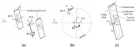
Figure 1.
Different coordinate system arrangements: (a) inertial coordinate system (ICS) and unfolded blade coordinate system (BCS); (b) top view of the ICS and BCS; and (c) BCS and inclined pitch axis coordinate system (PCS) [4].
The sign convention of the concerned variables is shown in Figure 2. A revolution of the blade was divided into four quartiles: the first quartile refers to , the second quartile refers to , the third quartile refers to and the fourth quartile refers to . Besides that, the fore half refers to and the aft half refers to .
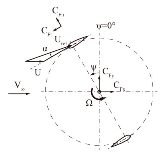
Figure 2.
Sign convention of the variables.
2.3. Computational Setup
In the present study, the ALM was implemented in the ANSYS Fluent platform together with user-defined functions. A computational domain of was built up to eliminate the blockage effect, and the wind turbine was located at the center (Figure 3a). The boundary conditions were set as follows: a velocity inlet of 7 m/s with a turbulence intensity of 5%, a pressure outlet of zero gauge pressure and symmetry on the other four boundaries. A hexagonal mesh with 1,166,480 elements in total was generated in ANSYS ICEM CFD, which was composed of three zones (Figure 3b). An inner zone of contained the turbine, with an element size of . A transition zone of was adjacent to the former, with a double element size using hanging nodes on the interface between zones. Lastly, an outer zone corresponded to the whole domain, with a quadruple element size growing larger toward the boundaries. The numerical settings in Fluent were decided based on previous studies [34,35]. The sheer stress transport (SST) k–ω turbulence model and semi-implicit method for pressure-linked equations consistent (SIMPLEC) algorithm were utilized. Other settings can be found in the previous literature of the authors [33].
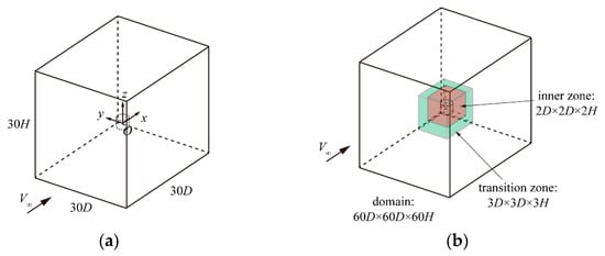
Figure 3.
(a) Computational domain and (b) three mesh zones of the domain (not to scale).
3. Validation
During the numerical computation, the average tangential force coefficient of a blade per revolution was calculated to confirm a convergence. In addition, the criterion was defined as the relative error between two consecutive revolutions lower than 0.25%. Simulation results were obtained and then analyzed.
A series of sensitivity analyses of the spatial discretization (mesh element size and blade element length) and temporal discretization (azimuthal angle step size) were carried out, and the instantaneous tangential force coefficients were compared. In terms of the meshes, besides a basic M1 mesh, as mentioned above, a refined M2 mesh was used as a comparison, with a smaller element size of . The total number of elements of M2 was 3,338,616, almost triple that of M1. The results with the two meshes exhibit good conformability in Figure 4a, with a relative error of 0.4% for the average tangential force coefficients. Therefore, the M1 mesh was selected for the following simulations. The blade element length is related to the Gaussian distribution width () in the ALM, which equaled the blade chord length in the present study. Three lengths of , and were chosen, and it was found that the relative errors of the two former lengths, compared to the latter, were 2.6% and 0.6%, respectively (Figure 4b). Thus, the blade element length was set to , corresponding to 27 elements in total for a blade. As for the azimuthal increments, simulations with azimuthal angle step sizes of 2.0° and 1.0° were executed. As shown in Figure 4c, the differences between the two results were quite tiny, with less than a 0.1% relative error. As such, an azimuthal angle step of 2.0° was determined in the present study.

Figure 4.
Instantaneous tangential force coefficients of a blade with different (a) meshes, (b) blade element lengths and (c) azimuthal angle step sizes.
The ALM employed in the present study had been validated in the aspect of power coefficients () of a VAWT for a wide range of tip-speed ratios [33]. The simulation results by the ALM showed satisfying agreement with the experimental data, especially for moderate-to-high tip-speed ratios. Other than that, the and of a blade on the equator were calculated and compared with the measured ones by Li et al. [36]. The wind turbine model used in the experiments had a diameter of 2 m and a span length of 1.2 m with two straight blades. The airfoil was NACA0021, and the chord length was 0.265 m. The inlet velocity of the wind tunnel was 8 m/s, and two moderate tip speed ratios, 2.58 and 2.19, were chosen to study. From Figure 5, it is clear that the calculated results fit well with experimental data. To be specific, the peaks of the in the fore half, as well as the in the aft half, were predicted well, but the peaks of the in the fore half and the in the aft half were overpredicted with acceptable errors.
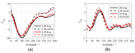
Figure 5.
Comparison of simulated instantaneous force coefficients against experimental data [36]: (a) normal and (b) tangential.
Therefore, the present ALM was proven to properly predict the aerodynamics of a VAWT, and the following studies were then carried out.
4. Results and Discussion
In this section, the effect of two pitch parameters, namely the fold angle and the incline angle, on the instantaneous and average aerodynamic forces of a blade is demonstrated in detail.
4.1. Fold Angle
To investigate the effect of the fold angle, the instantaneous forces and overall performance of the wind turbine with different fold angles from −2° to 8.5° were calculated, given an incline angle of 60°. The range of fold angles was determined in consideration of the power performance of the VAWT. The results are discussed below, which are similar to those of VAWTs with conventional pitch axes [6], as well as having some distinct characteristics.
First, the AoA, and of a blade element on the equator were assessed (Figure 6). The variations of the AoA versus azimuth showed that variations of the AoA were approximately proportional to the fold angles all around the revolution. With the increase of the fold angle, the AoA in the fore half of the revolution decreased (in absolute terms), while that in the aft half increased (in absolute terms). The opposite effect occurred with the decrease of the fold angle. The variations of the versus azimuth with different fold angles were similar to those of the AoA. The slight decrease of the in the second quartile—with a fold angle of −2° and, in the aft half, a fold angle of 8.5°—suggests that the blade experienced a stall for these azimuthal angles, which could be seen more apparently by the variations of the . As shown in Figure 6c, a sharp drop of the in the fore half after the peaks occurred for fold angles from 2° to −2°. A similar drop was observed in the aft half for large fold angles (8° and 8.5°). It is clear that the appearance of a stall happened earlier in the azimuth as it grew deeper. Besides the stall phenomena, variations of the versus azimuth were a bit complicated. For fold angles from −2° to 8.5°, the climbing of the in the first quartile was delayed backward, and lower peaks of the occurred at later azimuthal angles. A positive was seen in a narrower azimuthal range. On the contrary, the climbing of the in the third quartile was advanced forward, and the lowest peaks of the occurred with a fold angle of 4°. Furthermore, for a fold angle of 4°, two peaks of existed in the aft fore, with one in the third quartile and the other in the fourth quartile. When the blade was folded in the positive direction—namely, increasing the fold angles—two peaks grew simultaneously. However, when the blade was folded in the negative direction—namely, decreasing the fold angles—the first peak grew but the second declined. This is reasonable, since the performance in the aft half is influenced by that in the fore half for a VAWT.

Figure 6.
Instantaneous variables of a blade element on the equator with different fold angles: (a) angle of attack (AoA); (b) and (c) .
Next, the instantaneous aerodynamic forces, namely the , and , of a blade were examined with fold angles from −2° to 8° (Figure 7). The generally stayed positive in most of the azimuth range. With increasing fold angles, the peaks of the in the fore half reduced, and the climbing of the was delayed. Opposite changes could be seen in the aft half, making the variations of the flatter with larger fold angles. In addition, changes of the in the fourth quartile were greater when compared with those in the third quartile because of the performance in the fore half, similar to . As for the , its direction changed between quartiles. Different from the and , the effect of the fold angle on the was reversed at azimuthal angles of 90° and 270°. The increased in the windward half and decreased in the leeward half with increasing fold angles, which means that the blade folding movement in the positive direction strengthened the lateral force away from the main shaft. Additionally, the occurrence of a stall also resulted in a slight reduction of the . Variations of the showed that the fold angle intensified the fluctuations of . With increasing positive fold angles, the blade experienced larger aerodynamic forces upward in the fore half and downward in the aft half, which was reversed with negative fold angles. Moreover, the effect of the fold angle on the was much stronger in the aft half than that in the fore half.

Figure 7.
Instantaneous aerodynamic forces of a blade with different fold angles: (a) ; (b) and (c) .
As was mentioned above, the folding movement of the blades led to changes in both the pitch angle and the swept area. Variations of the swept area of the blades could also contribute to the variations in overall performance of the VAWT. However, as can be seen in Figure 8a, the variations of the swept area for fold angles from −2° to 8.5° were less than 0.3%, which could be neglected, suggesting that the variations of the overall performance of the VAWT were mainly owed to pitch movement. Variations of the versus the fold angle are shown in Figure 8b. As can be seen, the maximum was obtained at a fold angle of 4°, and it decreased gradually when the blades were folded in two directions. It is shown that the sensitivity of the to the folding movement in the negative direction was higher than that in the positive direction. However, the occurrence of a stall, caused by large positive fold angles (8.5° in this case), resulted in a sharp drop of the . The findings coincided with previous experimental results [4].
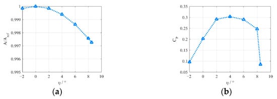
Figure 8.
Variables of a wind turbine with : (a) swept area (normalized by that of the unfolded blades) and (b) .
As for the average thrust of a blade, the grew when the blades were folded in the positive direction (shown in Figure 9). In addition, it diminished with the occurrence of a stall. The was approximately proportional to the fold angle. As a result, the fold angle strengthened the asymmetry of the lateral force of a blade. Fold angles above 2° led to lateral forces pointing to the windward half, and those lower than 2° led to forces pointing to the leeward half. The vertical forces kept downward for most of the fold angles, except for minor positive fold angles (2° in this case). In addition, the increased when the blades were folded in both directions.

Figure 9.
Average aerodynamic forces of a blade with : (a) ; (b) and (c) .
4.2. Incline Angle
The incline angle dominates the relationship between the pitch angle () and the fold angle. The pitch angle equals the fold angle with an incline angle of 90°, while the pitch angle remains constant regardless of the fold angle with the incline angle of 0°. In this way, the application of an inclined pitch axis slows the pitch movement, compared with a conventional pitch axis. The relationship among three variables is as follows [4]:
The effect of the incline angle on the overall performance of the VAWT was investigated with fold angles from −2° to 10°. The incline angle was set to 30°, 60°, 90°, 120° and 150°. Variations of the swept area of the wind turbine versus the fold angle for different incline angles are shown in Figure 10. As can be seen, variations of the swept area increased with the incline angles away from 90°, but were still quite tiny for the range of fold angles observed. The sensitivity of the to the fold angle diminished with the incline angles away from 90°. A similar effect could be found for the and . However, the effect on the was more complicated, which was the comprehensive result of both the variable modulus of aerodynamic forces resulting from the pitch angle and different decompositions of forces resulting from different orientations of the blades. For incline angles from 90° to 60°, vertical forces grew downward for most of the fold angles. Then, for incline angles from 60° to 30°, the vertical forces increased downward for the negative fold angles, but the vertical forces trended upward for the positive fold angles. The opposite changes were observed with . The upward vertical forces could diminish the burden of the gravity of the blades on the supporting structures of the wind turbine.
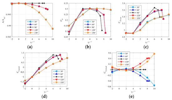
Figure 10.
Overall performance of a wind turbine with different incline angles: (a) swept area, (b) , (c) , (d) and (e) .
In addition, to clarify the effect of the incline angle, a pitch angle of 3° was selected to be constant for various incline angles—30°, 60°, 90°, 120° and 150°—leading to corresponding fold angles of 6°, 3.5°, 3°, 3.5° and 6°, respectively. The Average aerodynamic forces of the blade elements along the blade span were evaluated, as shown in Figure 11. It is apparent that incline angles away from 90° modified the distribution of aerodynamic forces to asymmetry about the equator. For the with , the peak appeared at the upper half of the blade and declined along the blade span downward. The trend was the opposite with . Besides that, the maximum with and 60° was 9.1% and 3.0% higher than that at the equator with , respectively. The asymmetry of the resulted in additional normal moments on the blade attachment points. Similar phenomena were found for the , leading to different tilting moments applied to the main shaft and the tower of the wind turbine. A 2.3% reduction of the tilting moment to the main shaft at z/H = −0.5 with was estimated, compared with that utilizing . The asymmetry of the caused the same results as the to a minor extent. As for the , variations along the blade span could be ignored in view of the values.
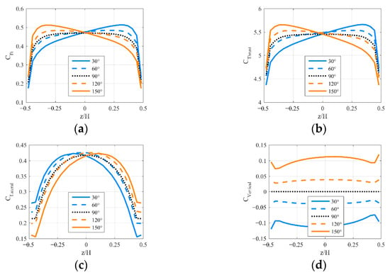
Figure 11.
Average aerodynamic forces along the blade span with different incline angles: (a) , (b) , (c) and (d) .
5. Conclusions
In the present study, the instantaneous and average aerodynamic forces of a VAWT with inclined pitch axes were simulated by an actuator line model. The effect of two pitch parameters, namely the fold angle and the incline angle, was illustrated, and major findings followed.
The fold angle changed the angles of attack directly and, in turn, the aerodynamic forces. Blade folding movement in the positive direction made the variations of the flatter and strengthened the instantaneous lateral forces away from the main shaft. Furthermore, the fold angle intensified the fluctuations of the . As for overall performance, the of the VAWT varied with different fold angles. The grew when the blades were folded in the positive direction, but the increased when the blades were folded in both directions. The direction of the average lateral force depended on the fold angle.
Diverse sensitivities of the power control could be obtained with different incline angles, since the sensitivity of the to the fold angle diminished with incline angles away from 90°. A similar effect could be found for the and . Opposite directions of the were seen for incline angles higher and lower than 90°. The upward vertical forces could diminish the burden of the gravity of the blades on the supporting structures of the wind turbine. From studies along the blade span, it is clear that incline angles away from 90° led to an asymmetric distribution of the aerodynamic forces about the equator. For the , the tilting moments applied to the main shaft and the tower of the wind turbine were different with various incline angles. Specifically, a 2.3% reduction of the tilting moment to the main shaft at z/H = −0.5 with was estimated, compared with that utilizing . Variations of the and were minor.
The present study lays a necessary foundation for dynamic pitch and adaptive passive pitch regulation of a VAWT with inclined pitch axes. Aerodynamic performance under a low tip-speed ratio with the occurrence of a deep stall is good to explore as a comparison and supplement to the present study. In addition, the effect of the asymmetric distribution of aerodynamic forces on the structural performance of the wind turbine under the conditions of various incline angles also needs to be investigated in detail in the future.
Author Contributions
Conceptualization, J.G.; formal analysis, J.G.; writing—original draft preparation, J.G.; writing—review and editing, T.Q. and L.L.; supervision, T.Q. and L.L. All authors have read and agreed to the published version of the manuscript.
Funding
This research was funded by the National Natural Science Foundation of China (No. 51875305).
Institutional Review Board Statement
Not applicable.
Informed Consent Statement
Not applicable.
Data Availability Statement
The data presented in this study are available on request from the corresponding author.
Conflicts of Interest
The authors declare no conflict of interest.
References
- Li, S.; Li, Y.; Yang, C.; Zhang, X.; Wang, Q.; Li, D.; Zhong, W.; Wang, T. Design and Testing of a LUT Airfoil for Straight-Bladed Vertical Axis Wind Turbines. Appl. Sci. 2018, 8, 2266. [Google Scholar] [CrossRef]
- Möllerström, E.; Gipe, P.; Beurskens, J.; Ottermo, F. A historical review of vertical axis wind turbines rated 100 kW and above. Renew. Sustain. Energy Rev. 2019, 105, 1–13. [Google Scholar] [CrossRef]
- Tummala, A.; Velamati, R.K.; Sinha, D.K.; Indraja, V.; Krishna, V.H. A review on small scale wind turbines. Renew. Sustain. Energy Rev. 2016, 56, 1351–1371. [Google Scholar] [CrossRef]
- Guo, J.; Zeng, P.; Lei, L. Performance of a straight-bladed vertical axis wind turbine with inclined pitch axes by wind tunnel experiments. Energy 2019, 174, 553–561. [Google Scholar] [CrossRef]
- Shah, O.R.; Jamal, M.A. Performance Evaluation of a 1 kW Variable Pitch-Straight Blade Vertical Axis Wind Turbine. J. Energy Resour. Technol. 2020, 142. [Google Scholar] [CrossRef]
- Rezaeiha, A.; Kalkman, I.; Blocken, B. Effect of pitch angle on power performance and aerodynamics of a vertical axis wind turbine. Appl. Energy 2017, 197, 132–150. [Google Scholar] [CrossRef]
- Chen, C.-C.; Kuo, C.-H. Effects of pitch angle and blade camber on flow characteristics and performance of small-size Darrieus VAWT. J. Vis. 2012, 16, 65–74. [Google Scholar] [CrossRef]
- Zhao, Z.; Wang, R.; Shen, W.; Wang, T.; Xu, B.; Zheng, Y.; Qian, S. Variable Pitch Approach for Performance Improving of Straight-Bladed VAWT at Rated Tip Speed Ratio. Appl. Sci. 2018, 8, 957. [Google Scholar] [CrossRef]
- Liang, Y.-B.; Zhang, L.-X.; Li, E.-X.; Zhang, F.-Y. Blade pitch control of straight-bladed vertical axis wind turbine. J. Cent. S. Univ. 2016, 23, 1106–1114. [Google Scholar] [CrossRef]
- Zhang, L.-X.; Liang, Y.-B.; Liu, X.-H.; Guo, J. Effect of blade pitch angle on aerodynamic performance of straight-bladed vertical axis wind turbine. J. Cent. S. Univ. 2014, 21, 1417–1427. [Google Scholar] [CrossRef]
- Zouzou, B.; Dobrev, I.; Massouh, F.; Dizene, R. Experimental and numerical analysis of a novel Darrieus rotor with variable pitch mechanism at low TSR. Energy 2019, 186. [Google Scholar] [CrossRef]
- Ferreira, C.S.; Scheurich, F. Demonstrating that power and instantaneous loads are decoupled in a vertical-axis wind turbine. Wind Energy 2014, 17, 385–396. [Google Scholar] [CrossRef]
- Nguyen, M.T.; Balduzzi, F.; Bianchini, A.; Ferrara, G.; Goude, A. Evaluation of the unsteady aerodynamic forces acting on a vertical-axis turbine by means of numerical simulations and open site experiments. J. Wind Eng. Ind. Aerodyn. 2020, 198. [Google Scholar] [CrossRef]
- Scheurich, F.; Fletcher, T.M.; Brown, R.E. Simulating the aerodynamic performance and wake dynamics of a vertical-axis wind turbine. Wind Energy 2011, 14, 159–177. [Google Scholar] [CrossRef]
- Dyachuk, E.; Rossander, M.; Goude, A.; Bernhoff, H. Measurements of the Aerodynamic Normal Forces on a 12-kW Straight-Bladed Vertical Axis Wind Turbine. Energies 2015, 8, 8482–8496. [Google Scholar] [CrossRef]
- Li, Q.A.; Maeda, T.; Kamada, Y.; Murata, J.; Furukawa, K.; Yamamoto, M. Effect of number of blades on aerodynamic forces on a straight-bladed Vertical Axis Wind Turbine. Energy 2015, 90, 784–795. [Google Scholar] [CrossRef]
- Li, Q.A.; Maeda, T.; Kamada, Y.; Murata, J.; Shimizu, K.; Ogasawara, T.; Nakai, A.; Kasuya, T. Effect of solidity on aerodynamic forces around straight-bladed vertical axis wind turbine by wind tunnel experiments (depending on number of blades). Renew. Energy 2016, 96, 928–939. [Google Scholar] [CrossRef]
- Peng, Y.-X.; Xu, Y.-L.; Zhan, S.; Shum, K.-M. High-solidity straight-bladed vertical axis wind turbine: Aerodynamic force measurements. J. Wind Eng. Ind. Aerodyn. 2019, 184, 34–48. [Google Scholar] [CrossRef]
- Delafin, P.L.; Nishino, T.; Wang, L.; Kolios, A. Effect of the number of blades and solidity on the performance of a vertical axis wind turbine. J. Phys. Conf. Ser. 2016, 753. [Google Scholar] [CrossRef]
- Rogowski, K.; Hansen, M.O.L.; Bangga, G. Performance Analysis of a H-Darrieus Wind Turbine for a Series of 4-Digit NACA Airfoils. Energies 2020, 13, 3196. [Google Scholar] [CrossRef]
- Rogowski, K.; Hansen, M.O.L.; Lichota, P. 2-D CFD Computations of the Two-Bladed Darrieus-Type Wind Turbine. J. Appl. Fluid Mech. 2018, 11, 835–845. [Google Scholar] [CrossRef]
- Song, C.; Wu, G.; Zhu, W.; Zhang, X.; Zhao, J. Numerical Investigation on the Effects of Airfoil Leading Edge Radius on the Aerodynamic Performance of H-Rotor Darrieus Vertical Axis Wind Turbine. Energies 2019, 12, 3794. [Google Scholar] [CrossRef]
- Wang, K.; Hansen, M.O.L.; Moan, T. Model improvements for evaluating the effect of tower tilting on the aerodynamics of a vertical axis wind turbine. Wind Energy 2015, 18, 91–110. [Google Scholar] [CrossRef]
- Lei, H.; Zhou, D.; Bao, Y.; Chen, C.; Ma, N.; Han, Z. Numerical simulations of the unsteady aerodynamics of a floating vertical axis wind turbine in surge motion. Energy 2017, 127, 1–17. [Google Scholar] [CrossRef]
- Lei, H.; Zhou, D.; Lu, J.; Chen, C.; Han, Z.; Bao, Y. The impact of pitch motion of a platform on the aerodynamic performance of a floating vertical axis wind turbine. Energy 2017, 119, 369–383. [Google Scholar] [CrossRef]
- Guo, Y.; Liu, L.; Gao, X.; Xu, W. Aerodynamics and Motion Performance of the H-Type Floating Vertical Axis Wind Turbine. Appl. Sci. 2018, 8, 262. [Google Scholar] [CrossRef]
- Hansen, M.O.L.; Sørensen, N.N.; Sørensen, J.N.; Michelsen, J.A. Extraction of lift, drag and angle of attack from computed 3D viscous flow around a rotating blade. In Proceedings of the European Wind Energy Conference (EWEC 97), Dublin, Ireland, 6–9 October 1997; pp. 499–501. [Google Scholar]
- Rahimi, H.; Schepers, J.G.; Shen, W.Z.; García, N.R.; Schneider, M.S.; Micallef, D.; Ferreira, C.J.S.; Jost, E.; Klein, L.; Herráez, I. Evaluation of different methods for determining the angle of attack on wind turbine blades with CFD results under axial inflow conditions. Renew. Energy 2018, 125, 866–876. [Google Scholar] [CrossRef]
- Jost, E.; Klein, L.; Leipprand, H.; Lutz, T.; Krämer, E. Extracting the angle of attack on rotor blades from CFD simulations. Wind Energy 2018, 21, 807–822. [Google Scholar] [CrossRef]
- Elsakka, M.M.; Ingham, D.B.; Ma, L.; Pourkashanian, M. CFD analysis of the angle of attack for a vertical axis wind turbine blade. Energy Convers. Manag. 2019, 182, 154–165. [Google Scholar] [CrossRef]
- Shen, W.Z.; Hansen, M.O.L.; Sørensen, J.N. Determination of angle of attack (AoA) for rotating blades. In Wind Energy: Proceedings of the Euromech Colloquium; Springer: Berlin/Heidelberg, Germany, 2006; pp. 205–209. [Google Scholar]
- Shen, W.Z.; Hansen, M.O.L.; Sørensen, J.N. Determination of the angle of attack on rotor blades. Wind Energy 2009, 12, 91–98. [Google Scholar] [CrossRef]
- Guo, J.; Lei, L. Flow Characteristics of a Straight-Bladed Vertical Axis Wind Turbine with Inclined Pitch Axes. Energies 2020, 13, 6281. [Google Scholar] [CrossRef]
- Balduzzi, F.; Bianchini, A.; Maleci, R.; Ferrara, G.; Ferrari, L. Critical issues in the CFD simulation of Darrieus wind turbines. Renew. Energy 2016, 85, 419–435. [Google Scholar] [CrossRef]
- Rezaeiha, A.; Kalkman, I.; Blocken, B. CFD simulation of a vertical axis wind turbine operating at a moderate tip speed ratio: Guidelines for minimum domain size and azimuthal increment. Renew. Energy 2017, 107, 373–385. [Google Scholar] [CrossRef]
- Li, Q.A.; Maeda, T.; Kamada, Y.; Murata, J.; Furukawa, K.; Yamamoto, M. The influence of flow field and aerodynamic forces on a straight-bladed vertical axis wind turbine. Energy 2016, 111, 260–271. [Google Scholar] [CrossRef]
Publisher’s Note: MDPI stays neutral with regard to jurisdictional claims in published maps and institutional affiliations. |
© 2021 by the authors. Licensee MDPI, Basel, Switzerland. This article is an open access article distributed under the terms and conditions of the Creative Commons Attribution (CC BY) license (http://creativecommons.org/licenses/by/4.0/).