Article

Study of Materials Behavior in a Monumental Vault Strengthened by a Carbon Net in a Mineral Matrix Subjected to Seismic Influence

1
Faculty of Civil Engineering, Wroclaw University of Science and Technology, Wybrzeze Wyspianskiego 27, 50-370 Wroclaw, Poland
2
Faculty of Civil Engineering, Cracow University of Technology, Warszawska 24, 31-155 Krakow, Poland
*
Author to whom correspondence should be addressed.
Appl. Sci. 2021, 11(3), 1015; https://doi.org/10.3390/app11031015
Submission received: 5 December 2020 / Revised: 12 January 2021 / Accepted: 20 January 2021 / Published: 23 January 2021
(This article belongs to the Special Issue Nondestructive Testing (NDT): Volume II)

Abstract

:
The application of the elasto-plastic material model known as the Barcelona Model (BM) for numerical assessment of a historical vault subjected to earthquake sequence is presented in this work. As a case study, part of a masonry vault erected in Southern Poland in the 12th century was chosen. For the study purposes, a 3D finite element model (FEM) of the vault was prepared using the ABAQUS/Standard software program. The essential details of the structure geometry were taken from the 3D scan of the vault. The first variant of the masonry vault was the structure without any strengthening, whereas the second variant was with strengthening system realized by application on composite materials, i.e., the carbon fiber reinforced cementitious matrix (C-FRCM). The results of the dynamic analysis revealed that an evident nonlinear performance of the masonry materials of the vault in both cases was detected for both FE models of the structure. The analysis proved that the foreshock–mainshock–aftershock sequence caused substantial damages in structural parts of the masonry vault. The distribution of plastic strains and damages allowed assessment of the impact of the full seismic sequence on the masonry vault. In the case of the unstrengthen vault the level of cracking and stiffness loss reached 90%. In the case of the vault strengthened with the FRCM system the tensile damage level was significantly lower. It did not exceed 30%. In addition, the first plastic zone of the unstrengthened masonry structural elements of the vault became visible after the foreshock.

1. Introduction

The investigations of destructions of monumental masonry vaults due to strong kinematic seismic loading have uncovered that the protection of these types of structures is a difficult technical task [1,2,3,4]. In particular, for historical structures located on seismic activity regions, the kinematic loading generated by seismic events are one of the most destructive factors [4,5]. Hence, monumental structures of this type, which are memorable heritage landmarks, have to be secured and, if necessary, strengthened against seismic loadings [6,7,8,9]. Taking into consideration the assessment methods which were proposed by different researchers [4,5,6,7,8,9], the numerical evaluation of damages in structures subjected to seismic events is significant stage in designing strengthening. Calculations with nonlinear plastic material models provide good quality data for strengthening the structural parts that are at risk of being destroyed by strong seismic events [10,11,12]. It must be emphasized, that the majority of seismic mainshocks are usually preceded by foreshocks and succeeded by aftershocks within a short period of time [13,14,15,16,17]. Regarding the periodic mechanism of earthquake loadings, it is rational to consider the full sequence of the seismic events that may load the structure. Regarding the safety of the masonry vaults that are exposed to seismic influences, it is reasonable to consider the set of issues that were introduced by researchers. The protection of these types of monumental structures, the applications of non-linear materials for their assembling, mechanism of earthquake loadings, and types of the strengthening system are issues that are significant for the prevention of potential destruction.
In this work, the numerical assessment of damages to a monumental masonry vault exposed to kinematic loading generated by a foreshock–mainshock–aftershock seismic sequence is presented. This case study was based on a vault which is a structural part of the basilica erected in Southern Poland in the 12th century. In the numerical simulations, the vault was exposed to a foreshock–mainshock–aftershock earthquakes sequence which was recorded in Central Italy, i.e., Mascioni, in the Province of L’Aquila, in 2017 [18]. The main objective of the analysis is the comparison of the dynamic performance of two variants of the structure under the investigated seismic sequence. The first variant of the masonry vault was the structure without any strengthening, whereas the second variant was with a strengthening system realized by the application of composite materials, i.e., a carbon fiber reinforced cementitious matrix (C-FRCM). In order to evaluate the impact of the studied seismic events on the investigated vault, the Barcelona Model (BM) was applied as a constitutive elastoplastic model of the masonry material [19]. The research was divided into four stages. The general framework of the investigation is shown in Figure 1.

2. Materials and Methods

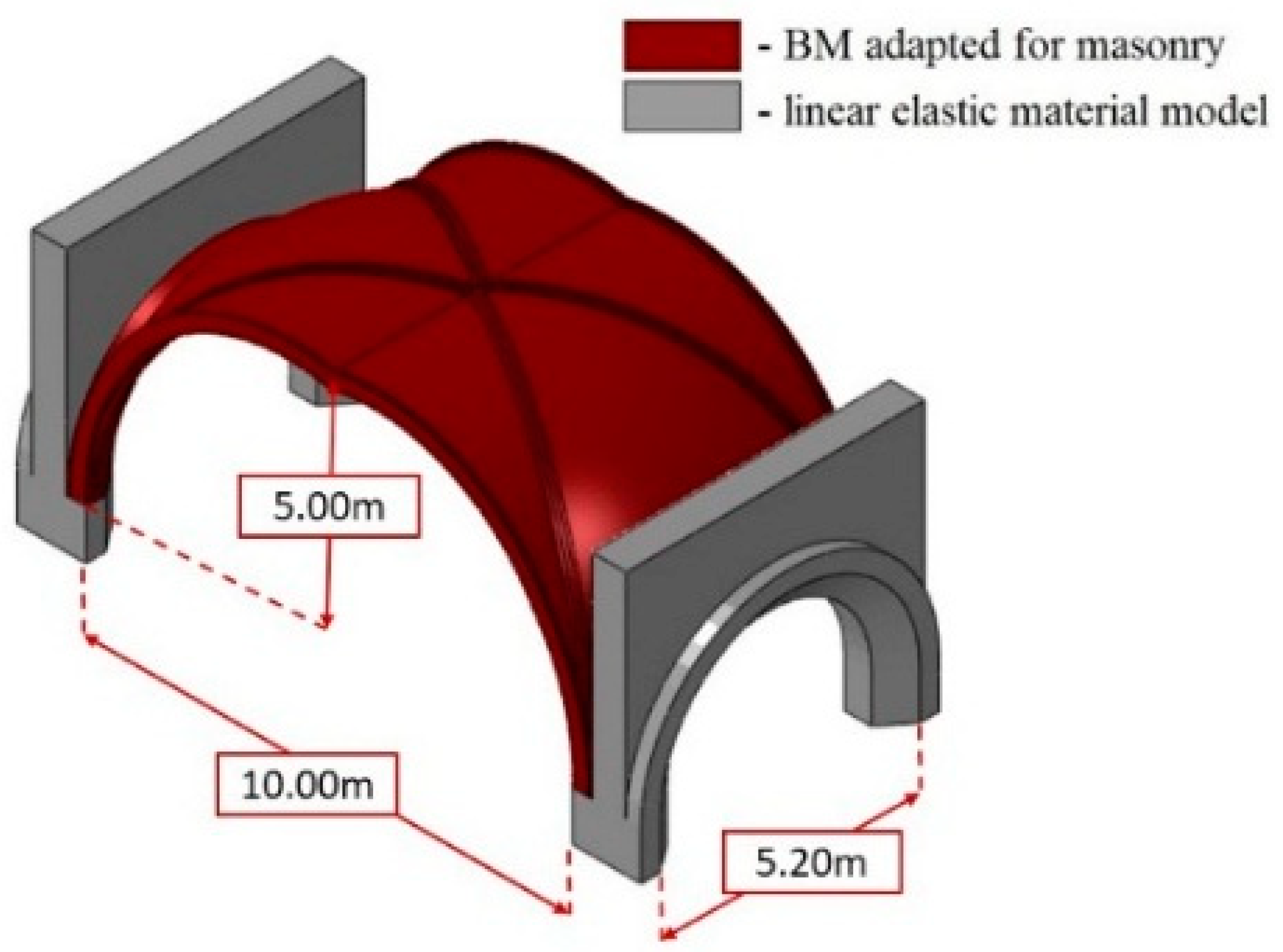
2.1. Geometry of the Vault

The analyzed masonry vault, which was chosen as a case study, is a structural part of the basilica erected in Southern Poland in the years 1392–1430.
In order to create a geometric model we used data acquired with a 3D laser scanner (Figure 2) and photographs using the orthophotogrammetry method [20].
For the purpose of the inventory of the structure of the church vaults a laser scanner was used, obtaining more than 20 scans of the interior under and above the vaults, and spherical photographs in shades of gray and color. Point clouds recorded in individual files were combined. The exact positioning of the scans in relation to each other was made possible by reference balls. Spherical objects with a known diameter were placed in areas common to subsequent scans before the start of the scan.
At the model development stage, the scan points relevant to the rib curvature were connected to form a spatial, broken polyline. Important profiles, i.e., sections of ribs and walls were also drawn. Next, horizontal projections were drawn and the layout of the vault ribs was marked. Imported rib curves were used to draw the arches. The arches had common knots in the vault’s armpits and at the intersection of ribs, and their curves were selected by changing the value of the rays. Next, drawings of rib cross-sections through selected axes were made. Next, individual vault fields were described and drawn parametrically, obtaining spatial shells.
The effect of these actions was to obtain spatial coatings of individual vaults. In this way a surface model of the entire church vault was obtained, on which analyses could be made.
Similar to the 3D scanning, verification of the spatial model of the vaults was obtained using the orthophotogrammetry method. The photogrammetric methods of measurement used photography for engineering tasks and carried out the inventory of the monuments. Photogrammetry allows the collection of information in a non-contact and non-invasive way. It is often the best method in the measurement of inaccessible elements, objects with irregular shapes and where data on the structure and texture of examined surfaces are necessary and it is not feasible to make 3D scans—e.g., for financial reasons.
The main task was to create a 3D textured object model and orthophotoplan of the vaults on this basis. The work consisted of the following stages: taking photos, aligning photos and creating a rare point cloud, building a dense point cloud, building a three-dimensional polygonal model, texturing the model, creating an orthophotoplan and exporting results.
The mosaic method was used to create the texture. This method mixes low-frequency components on overlapping photos to avoid visible cutting lines, while high-frequency components responsible for texture details are taken from the photos with good resolution and the frame plane maximally parallel to the photographed surface. Since in this case the model is for illustration purposes only, it is limited by a 4096 × 4096 pixel texture.
The creation of the orthophotoplan using Agisoft Metashape 1.5.5 software was based on the data of the original images and the reconstructed model, which allowed to create a high resolution image. The mosaic method was used again. The result of this stage was an orthophotoplan in a TIFF file with a resolution of 6749 × 18,320 pixels. The pixel size was taken as 0.004056 m.
Additionally, the orthophotoplan was processed in Adobe Photoshop CC 2018 (19.0) graphic software. Contrast, color brightness and image sharpness were enhanced. The final orthophotoplan was used as a base for vault 2D and 3D models.
Basing on the resulting spatial models (3D scans joined into one point cloud and orthophotogrammetry), the following geometrical parameters of the model were assumed in further analysis:
  • Vault coatings are 16 to 28 cm thick,
  • The span of the vaults of the main nave is about 10.0 m, the side aisles −5 m,
  • The width of the vault ribs is 20 and 29 cm.
The real view of the analyzed vault part and effect of using the 3D laser scan and ortophotography are shown on Figure 3. The historical drawings, new drawings and model of the analyzed part of the vault are shown on Figure 4, Figure 5 and Figure 6.

2.2. Masonry and FRCM Material Testing

Material parameters (Table 1) for calculations and the numerical model were adopted based on the results of laboratory destructive tests (DT) (Figure 7), non-destructive tests (NDT) and quasi-non-destructive tests (QNDT) described in [20,21,22] and compared with the our earlier test results [23]. The analyzed vault is a brick structure, an anisotropic material build with two basic elements: small-sized ceramic elements (bricks and/or stones) and mortars joining them [24]. According to [22,23], taking into account the existing computational possibilities and the degree of their complication, it is not possible to analyze larger objects or their parts, taking into account the division of the material into these elements. Consequently, it is supposed that when analyzing larger elements or entire structures, the material can be treated as isotropic with elastic properties. In order to determine the parameters of the vaults as an isotropic material, it is necessary to carry out the homogenization formulas (1–5)—this allows the determination of the subsequent material parameters based on the factors of the components and the interactions between them. The elementary factor to be determined is Young’s modulus. The authors based on the approach presented in [25,26].
v ¯ y = σ ¯ x ( 2 ) / σ ¯ y ( 2 )
v ¯ x = σ ¯ y ( 1 ) / σ ¯ x ( 1 )
E ¯ x = σ ¯ x ( 1 ) ( 1 v ¯ x v ¯ y ) / ϵ ¯ x ( 1 )
E ¯ y = σ ¯ y ( 2 ) ( 1 v ¯ x v ¯ y ) / ϵ ¯ y ( 2 )
G ¯ = τ ¯ x y ( 3 ) / γ ¯ x y ( 3 )
where:
(i) Identifies the case of the displacements under consideration:
(1)
Compression—tensile in the x direction (Figure 5b),
(2)
Compression—tension in the y direction,
(3)
Shear in xy plane.

2.3. FE Model of the Masonry Vault

The principal objective of the FE simulations was the comparison of the dynamic performance of the unstrengthened and strengthened masonry vault (Figure 8). Hence, two variants of the structure’s FE model were analyzed. In the first variant it was assumed that the vaults are unstrengthened. In the second variant, the strengthening was applied to the top as well as bottom surfaces of the vault. They were upgraded with strengthening system realized by application of composite materials, i.e., carbon net + mortar = carbon fiber reinforced cementitious matrix (C-FRCM). The masonry elements of the vault were realized with solid elements [27] for both variants of the structure. For the second variant, the C-FRCM strengthening system was modeled as shell elements. The ‘Tie’ option was used as a connection between the masonry vault and C-FRCM [27]. For the purpose of this study, i.e., analysis of the plastic behavior of the vault under a series of seismic shocks, the ABAQUS/Standard software program [27] was introduced and a finite element (FE) model of the vault was composed. The 3D numerical model was prepared using the quadratic tetrahedral elements of type C3D10 (for the masonry structural parts) and quadratic triangular elements of type STRI65 (for C-FRCM strengthening system) available in the ABAQUS element library. The complete number of nodes and elements equaled 109,964 and 62,260, correspondingly.
For the investigated variants of the FE model of the masonry vault, the non-linear plastic material model was implemented, since the evaluation of seismic-induced damages was the main purpose of the numerical simulations. Hence, the concrete damage plasticity model (CDP), also known as the Barcelona Model (BM) was used for masonry parts of the vault [25].
The CDP model, applied in the ABAQUS/Standard software program, makes it possible to present all occurrences typical for the material that occurs during cyclic loading [19]. The CDP model is generally dedicated to concrete material structures and it describes the isotropic features of the concrete. This model uses conceptions of the combination of non-associated multi-hardening plasticity and scalar damaged elasticity to represent the inelastic behavior of concrete and to describe the irreversible damage that occurs during the fracturing process. Further material factors for tension and compression are specified in the mathematical formulation of the CDP model that allows simulating accurately the behavior of the material in a complex state of stress. The yield surface is provided by hardening variables expressing equivalent plastic strains: by two hardening variables representing equivalent plastic strains: ε ˜ t p l and ε ˜ c p l , linked to failure mechanisms under tension and compression loading, respectively. To control damage evolution of the material stiffness degradation scalar value d, tensile damage variable d t , compressive damage variable d c are applied (SDEG, DAMAGET and DAMAGEC, respectively).
Equivalent plastic strain ε ˜ p l (marked in the ABAQUS/Standard as PEEQ—for compression, PEEQT—for tension) describes total plastic strain level in elements. This parameter allows to determine increases of plastic strain for every step of analysis and to follow the process of strain accumulation. Tensile and compressive stiffness degradation parameters depend on the level of equivalent plastic strain ε ˜ p l :
d c = d c ( ε ˜ c p l )
d t = d t ( ε ˜ t p l )
The behavior of masonry material structural parts is diverse compared to concrete material elements (the main feature of masonry is anisotropy). The primary conditions and assumptions, at which the BM can be realized for masonry material structures, have been presented in [22]. In this work, the major factors for the investigated masonry vault were assumed on the basis of Table 1 and [28,29] as follows: E = 9.48 GPa (elasticity modulus), ρ = 1800 kg/m3 (mass density), ν = 0.16 (Poisson’s ratio), fc = 12.30 MPa (compressive strength), ft = 2.00 MPa (tensile strength). The constitutive parameters of BM were adopted as follow: β = 38 o (dilation angle), m = 1 (eccentricity of the plastic potential surface), f = 1.5 (ratio of initial equibiaxial compressive yield stress to initial uniaxial compressive yield stress), K c = 0.6 (coefficient determining the shape of the deviatoric cross-section), μ = 0 (viscosity parameter) [29]. The scalar damage variable for compression and tension are delivered in Table 2. Both scalars are depended on the crushing or cracking strains.
In the second variant of the vault the strengthening system was applied. The elastic material parameters of the composite material C-FRCM were assumed as follows: E = 240 GPa (elasticity modulus), ρ = 1.78 g/cm3 (mass density) and ν = 0.26 (Poisson’s ratio) [20].

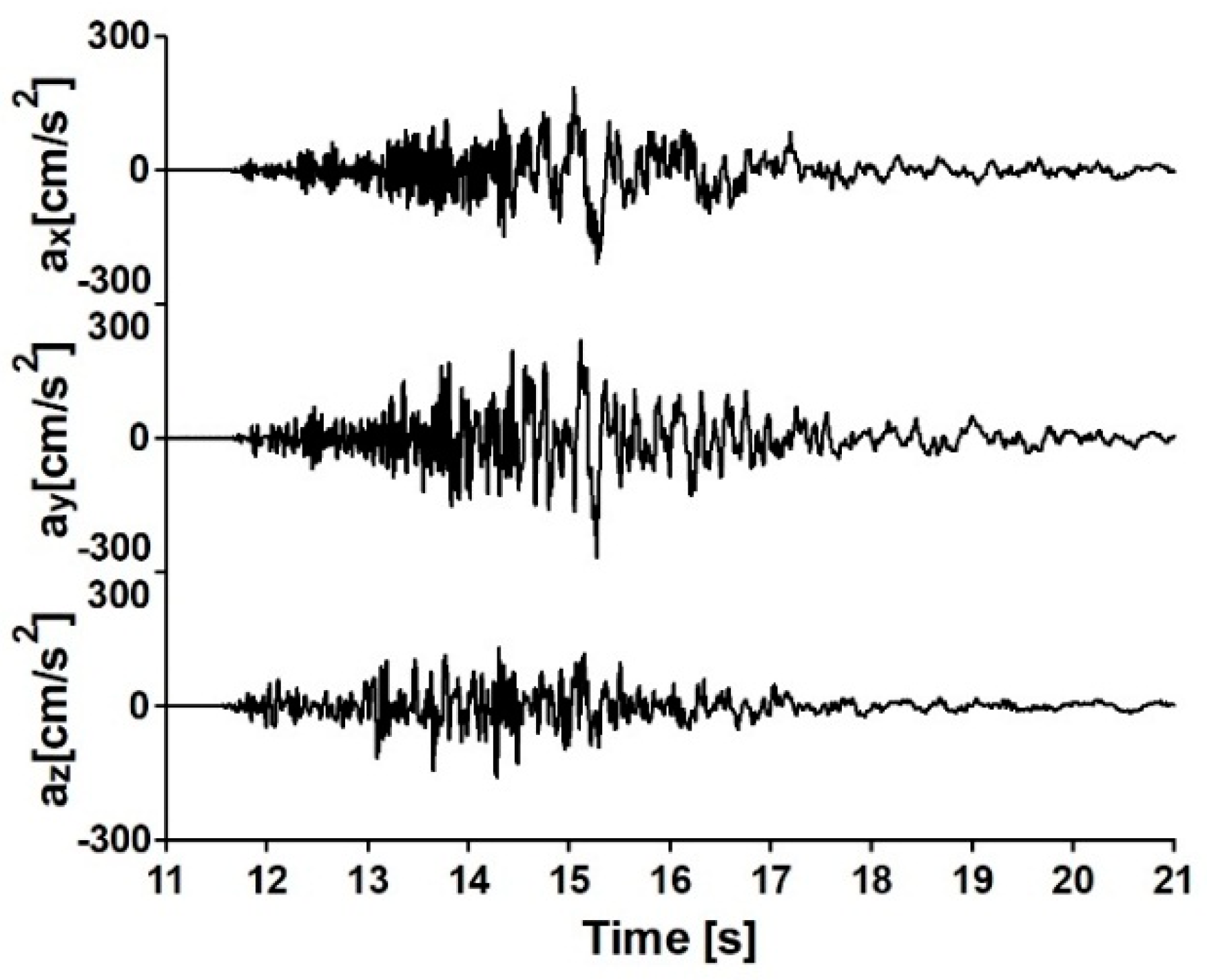
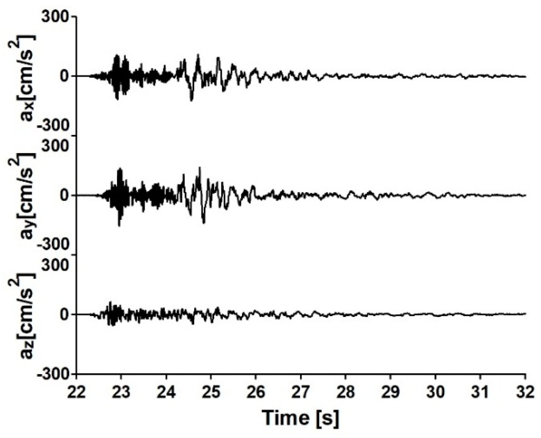
2.4. Data of the Seismic Sequence

In the numerical dynamic simulations, seismic events registered in Mascioni in the Province of L’Aquila, Italy, were used as kinematic loadings of the structure [18]. The Richter magnitude (ML) of the first shock equal to 5.4, whereas the ML of the second and third shock equal to 5.3 and 5.1, respectively. Time histories of accelerations of the sequence of the seismic events in three directions are presented in Figure 9, Figure 10 and Figure 11. The peak ground accelerations (PGA) of the kinematic loadings are delivered in Table 3. The accelerations were applied in three directions to the FE model.

2.5. Methods of Dynamic Investigation

The dynamic assessment of the masonry vault under the examined seismic loadings was made using full-time history analysis (THA). It was completed with the Hilber–Hughes–Taylor time integration algorithm implemented in the ABAQUS/Standard software program for a direct step-by-step calculation [24]. The integration step varied in the range from 10−5 to 10−2 s, regarding convergence requirements since the progressive damage and failure model of masonry elements implements strong material nonlinearity. In the calculations, the time shift between the first, second and third seismic events equaled 1 s and was applied as a quasi-static step realized by implicit dynamic analysis [24]. As demonstrated, the total unloading of the FE model, between examined seismic events, was realized.
Damping properties of the structure were implemented by the Rayleigh model of damping. Damping factor values were assumed for masonry material structures [11]. For the used model of damping coefficients α (for mass proportional damping) and β (for stiffness proportional damping) were applied. The values were calculated for damping ratios of 3.0%. Such factors of the Rayleigh model of damping were defined as the properties of material since ABAQUS/Standard provides this as a part of the material formulation [24].

3. Results

For the assessment of the influence of the investigated seismic sequence on the masonry vault, the distribution of the following BM variables was analyzed: tensile equivalent plastic strain (PEEQT), tensile damage variable (DAMAGET), compressive equivalent plastic strain (PEEQ), compressive damage variable (DAMAGEC), stiffness degradation variable (SDEG).
The propagation of the BM variables of the masonry material vault, which is not strengthened with composite material, are presented in Figure 12 as results of the vault response to the 1st (Figure 12a), the 2nd (Figure 12b) and the 3rd shock (Figure 12c). In Figure 12 the plastic zones and emergent plastic zones are delivered. It can be observed that the first significant plastic zone on the unstrengthened masonry vault manifests immediately after the 1st shock (Figure 12a). After the 2nd foreshock, the plastic zone increased and also some new areas become plastic (Figure 12b). After the 3rd shock the plastic zones increased. However, the new areas of plasticization did not appear. The areas affected by plasticization after the full sequence of seismic events, located throughout the whole thickness of the vault in the key points of the extreme left and right spans, are evidently noticed. Clearly visible plastic zones occurred also above the support areas of each span. In simulations based on the second variant of the model (strengthened with the C-FRCM composite), it should be highlighted that the plastic zones emerged only after the entire seismic sequence (see Figure 13b and Figure 14b).
The observed location of the masonry material plasticization indicated areas which potentially may undergo tensile damage and loss of stiffness. The distribution of cracking after the whole seismic sequence, in terms of the tensile damage variable (DAMAGET), are compared in Figure 13 for both variants: the unstrengthen masonry vault and the vault strengthened with the C-FRCM composite material. Next, the distribution of the loss of stiffness, in terms of the stiffness degradation variable (SDEG) for both variants, are shown in Figure 14a,b, respectively.
The comparisons presented in Figure 13 and Figure 14 explicitly indicated positive influence of the strengthening system on the dynamic performance of the masonry monument. In the case of the unstrengthened vault both variables, the level of cracking and stiffness loss, reached 90% (indicated by the red zones in Figure 13a and the red points in Figure 14a, respectively). In the case of the vault strengthened with the C-FRCM system the tensile damage level is significantly lower—the value of the DAMAGET variable did not exceed 30% (indicated by the green zones in Figure 13a). In the case of the strengthened variant of the vault the loss of the total stiffness is significantly smaller compared to the case of the unstrengthen structure (see Figure 14b).

4. Conclusions

Numerical evaluation of the plastic behavior and progress of the damages to a masonry material vault exposed to the full foreshock–mainshock–aftershock seismic sequence was carried out using the Barcelona Model and ABAQUS/Standard software. Two variants of the structure were analysed: the unstrengthen vault and the vault strengthened with the carbon fiber reinforced cementitious matrix (C-FRCM).
The results showed that the full foreshock–mainshock–aftershock seismic sequence can cause considerable damages in structural parts of the studied masonry vault. The propagation of plastic strain and damages permitted assessment of the impact of the full foreshock–mainshock–aftershock sequence on the masonry structural part. The results indicate that the first plastic zone of the unstrengthened masonry material vault manifests after the first shock.
Based on the results of the simulations, it is obvious that numerical analysis with the non-linear constitutive material models of masonry parts are practical and efficient mathematical tools. Taking into consideration the effects of the analysis, it is possible to determine the probable location of the zones damaged by the destruction process during the kinematic loading caused by the whole seismic sequence. Hence, the chosen, as well as elaboration of strengthening of a masonry structure is possible.
Regarding, the historical value of the investigated structure the techniques that would allow the least possible intervention in the historical tissue of the structure is strongly recommended. The recovery, as well as reinforcement of the earthquake resistance of masonry material parts of the vault, can be accomplished by application of the composite materials. The received distribution of the tensile damages and loss of stiffness of the masonry vault due to the full seismic sequence enables the preparation of the proposal of strengthening the old monumental structure with particular composite materials (e.g., the carbon fiber reinforced cementitious matrix). From the numerical examination, it is strictly visible that this type of strengthening makes the structure more durable regarding the seismic loading.

Author Contributions

Conceptualization, I.D., Ł.B., J.D., and J.J.; methodology, I.D., J.D. and Ł.B.; software, I.D. and Ł.B.; validation, I.D., Ł.B., J.D. and J.J.; formal analysis, I.D.; investigation, Ł.B.; resources, Ł.B.; data curation, I.D. and Ł.B.; writing—original draft preparation, I.D. and Ł.B.; writing—review and editing, I.D. and Ł.B.; visualization, Ł.B.; supervision, J.J.; project administration, Ł.B.; funding acquisition, J.D. All authors have read and agreed to the published version of the manuscript.

Funding

This research received no external funding.

Institutional Review Board Statement

Not applicable.

Informed Consent Statement

Not applicable.

Data Availability Statement

Data is contained within the article.

Conflicts of Interest

The authors declare no conflict of interest.

References

  1. Bertolesi, E.; Adam, J.M.; Rinaudo, R.; Calderón, P.A. Research and practice on masonry cross vaults—A review. Eng. Struct. 2019, 180, 67–88. [Google Scholar] [CrossRef]
  2. Chang-Hai, Z.; Zhi, Z.; Shuang, L.; Li-Li, X. Seismic analyses of a RCC building under mainshock–aftershock seismic sequences. Soil Dyn. Earthq. Eng. 2015, 74, 46–55. [Google Scholar]
  3. Cińcio, A. Numerical Analysis of Dynamic Resistance on Semi-Seismic Tremors of Low Buildings with Application of Spatial Object Models. Ph.D. Thesis, Silesian University of Technology, Gliwice, Poland, 2004. [Google Scholar]
  4. Thamboo, J.; Bandara, J.; Perera, S.; Navaratnam, S.; Poologanathan, K.; Corradi, M. Experimental and Analytical Study of Masonry Subjected to Uniaxial Cyclic Compression. Materials 2020, 13, 4505. [Google Scholar] [CrossRef] [PubMed]
  5. D’Altri, A.M.; Castellazzi, G.; Miranda, S.; Tralli, A. Seismic-induced damage in historical masonry vaults: A case-study in the 2012 Emilia earthquake-stricken area. J. Build. Eng. 2017, 13, 224–243. [Google Scholar] [CrossRef]
  6. Asteris, P.G.; Douvika, M.G.; Apostolopoulou, M.; Moropoulou, A. Seismic and Restoration Assessment of Monumental Masonry Structures. Materials 2017, 10, 895. [Google Scholar] [CrossRef] [Green Version]
  7. Valvona, F.; Toti, J.; Gattulli, V.; Potenza, F. Effective seismic strengthening and monitoring of a masonry vault by using Glass Fiber Reinforced Cementitious Matrix with embedded Fiber Bragg Grating sensors. Compos. Part B Eng. 2017, 113, 355–370. [Google Scholar] [CrossRef]
  8. Ferretti, E.; Pascale, G. Combined Strengthening Techniques to Improve the Out-of-Plane Performance of Masonry Walls. Materials 2019, 12, 1171. [Google Scholar] [CrossRef] [Green Version]
  9. Corradi, M.; Castori, G.; Sisti, R.; Borri, A.; Pesce, G.L. Repair of Block Masonry Panels with CFRP Sheets. Materials 2019, 12, 2363. [Google Scholar] [CrossRef] [Green Version]
  10. Krajewski, P.; Hojdys, Ł. Experimental studies on buried barrel vaults. Int. J. Archit. Herit. Conserv. Anal. Restor. 2015, 9, 834–843. [Google Scholar] [CrossRef]
  11. Pineda, P. Collapse and upgrading mechanisms associated to the structural materials of a deteriorated masonry tower. Nonlinear assessment under different damage and loading levels. Eng. Fail. Anal. 2016, 63, 72–93. [Google Scholar] [CrossRef]
  12. Valente, M.; Milani, G. Earthquake-induced damage assessment and partial failure mechanisms of an Italian Medieval castle. Eng. Fail. Anal. 2019, 99, 292–309. [Google Scholar] [CrossRef]
  13. Chiozzia, A.; Grillanda, N.; Milani, G.; Tralli, A. UB-ALMANAC: An adaptive limit analysis NURBS-based program for the automatic assessment of partial failure mechanisms in masonry churches. Eng. Fail. Anal. 2018, 85, 201–220. [Google Scholar] [CrossRef]
  14. Lin, C.H. Foreshock characteristics in Taiwan: Potential earthquake warning. J. Asian Earth Sci. 2009, 34, 655–662. [Google Scholar] [CrossRef]
  15. Ruiz-García, J.; Negrete-Manriquez, J.C. Evaluation of drift demands in existing steel frames under as-recorded far-field and near-fault mainshock–aftershock seismic sequences. Eng. Struct. 2011, 33, 621–634. [Google Scholar] [CrossRef]
  16. Shin, J.; Jeon, J.S.; Kim, J.H. Mainshock-aftershock response analyses of FRP-jacketed columns in existing RC building frames. Eng. Struct. 2018, 165, 315–330. [Google Scholar] [CrossRef]
  17. Zhang, S.; Wang, G.; Sa, W. Damage evaluation of concrete gravity dams under mainshock–aftershock seismic sequences. Soil Dyn. Earthq. Eng. 2013, 50, 16–27. [Google Scholar] [CrossRef]
  18. Luzi, L.; Pacor, R.; Puglia, R. Italian Accelerometric Archive v3.0. Istituto Nazionale di Geofisica e Vulcanologia. Dipartimento della Protezione Civile Nazionale. Available online: http://itaca.mi.ingv.it/ItacaNet_30/#/home (accessed on 11 July 2020).
  19. Lee, J.; Fenves, G.L. Plastic-damage model for cyclic loading of concrete structures. J. Eng. Mech. 1998, 124, 892–900. [Google Scholar] [CrossRef]
  20. Bednarz, Ł.J.; Jasieńko, J.; Rutkowski, M.; Nowak, T.P. Strengthening and long-term monitoring of the structure of an historical church presbytery. Eng. Struct. 2014, 81, 62–75. [Google Scholar] [CrossRef]
  21. Drygala, I.J.; Dulinska, J.M.; Bednarz, Ł.; Jasienko, J. Seismic Performance of a Historical Apartment Building Using a Barcelona Model (BM) Adapted for Masonry Walls. Key Eng. Mater. 2017, 747, 646–652. [Google Scholar] [CrossRef]
  22. Wawrzynek, A.; Cińcio, A.; Fedorowicz, J. Numerical verification of the Barcelona Model adapted for brick walls. In Proceedings of the 7th International Masonry Conference (7IMC), London, UK, 30 October–1 November 2006; Volume 30, pp. 31–84. [Google Scholar]
  23. Jasieńko, J.; Łodygowski, T.; Rapp, P. Naprawa, Konserwacja i Wzmacnianie Wybranych, Zabytkowych Konstrukcji Ceglanych; Dolnośląskie Wydawnictwo Edukacyjne: Wroclaw, Poland, 2006. [Google Scholar]
  24. Bednarz, Ł. Praca Statyczna Zabytkowych, Zakrzywionych Konstrukcji Ceglanych Poddanych Zabiegom Naprawy i Wzmacniania. Ph.D. Thesis, Wrocław University of Science and Technology, Wrocław, Poland, 2008. [Google Scholar]
  25. Lopez, J.; Oller, S.; Onate, E.; Lubliner, J. A homogeneous constitutive model for masonry. Int. J. Numer. Methods Eng. 1999, 46, 1651–1671. [Google Scholar] [CrossRef]
  26. Kuczma, M.; Wybranowska, K. Numerical homogenization of elastic brick masonry. Civ. Environ. Eng. Rep. 2005, 1, 135–152. [Google Scholar]
  27. Simulia ABAQUS. Users’ Manual Documentation, Version 6.13; Simulia: Johnston, RI, USA, 2013. [Google Scholar]
  28. Mrożek, M. Numeryczna Symulacja Wzmacniania Matami CFRP Konstrukcji Murowych z Cegły. Ph.D. Thesis, Silesian University of Technology, Gliwice, Poland, 2012. [Google Scholar]
  29. Passowicz, A.; Norberciak, D.; Sielicki, P. Analiza Numeryczna Konstrukcji Kościoła Najświętszej Marii Panny na Ostrowie Tumskim w Poznaniu. Master’s Thesis, Poznań University of Technology, Poznań, Poland, 2005. [Google Scholar]
Figure 1. General concept of the investigation.
Applsci 11 01015 g001
Figure 2. Laser scanner used to create a geometric model (a) and representative scan output (b).
Applsci 11 01015 g002
Figure 3. Analyzed vault part: (a) real view; (b) 3D low resolution laser scan—intrados view; (c) high resolution ortophotography—3D intrados view.
Applsci 11 01015 g003
Figure 4. Historical drawings of the vault—intrados view, with highlighted analyzed vault part.
Applsci 11 01015 g004
Figure 5. Drawings of analyzed vault part based on 3D laser scan and ortophotography: (a) intrados view; (b) cross section view.
Applsci 11 01015 g005
Figure 6. Three-dimensional (3D) finite element model (FEM) of the vault with highlighted analyzed vault part: (a) extrados axonometric view; (b) cross-section view.
Applsci 11 01015 g006
Figure 7. Destructive laboratory tests (DT) of the materials used in the analyzed vault part: (a) masonry brick compressive strength; (b) carbon net tensile strength; (c) example diagram of compressive strength; (d) example diagram of strength—slip.
Applsci 11 01015 g007
Figure 8. FE model of the studied masonry vault.
Applsci 11 01015 g008
Figure 9. Time histories of acceleration in three directions of the 1st shock.
Applsci 11 01015 g009
Figure 10. Time histories of acceleration in three directions of the 2nd shock.
Applsci 11 01015 g010
Figure 11. Time histories of acceleration in three directions of the 3rd shock.
Applsci 11 01015 g011
Figure 12. Tensile equivalent plastic strain (PEEQT) due to: (a) the 1st; (b) the 2nd and (c) the 3rd shock.
Applsci 11 01015 g012
Figure 13. Distribution of the stiffness degradation variable (SDEG) for: (a) the first variant of model—the unstrengthen vault; (b) the second variant—the vault strengthened with the FRCM.
Applsci 11 01015 g013
Figure 14. Distribution of the tensile damage variable (DAMAGET) for: (a) the first variant of model—the unstrengthen vault; (b) the second variant—the vault strengthened with the FRCM.
Applsci 11 01015 g014
Table 1. Material parameters of the masonry and carbon net used for reinforcement.
MaterialModulus of Elasticity
E
Poisson’s Ratio
ν
Shear Modulus
G
[MPa][−][MPa]
masonry94800.64300
carbon net240,0000.45000
Table 2. Constitutive parameters of the Barcelona Model (BM) [29].
Tension StiffeningTension Damage
Stress
[MPa]
Cracking strain [−]dt
[%]
Cracking strain
[−]
0.200.000.000.00
0.050.0007920.750.000792
Compression HardeningCompression Damage
Stress
[MPa]
Crushing strain [−]dc
[−]
Crushing strain
[−]
2.000.000.000
0.50.0079200.750.00792
Table 3. The peak ground accelerations (PGA) of the seismic shocks.
DateSeismic EventThe Peak Ground Accelerations (PGA) [cm/s2]
E–WN–SVertical
2017-01-18 10:14:121st shock203.92247.21125.18
2017-01-18 10:25:262nd shock208.57265.97157.55
2017-01-18 13:33:373rd shock123.40153.8564.28
Publisher’s Note: MDPI stays neutral with regard to jurisdictional claims in published maps and institutional affiliations.

