Design of Geometrical Parameters and Kinematical Characteristics of a Non-circular Gear Transmission for Given Parameters


Abstract
1. Introduction
- in flying drum shear drives as a synchronization mechanism which operates in acceleration-deceleration mode. In the period between two cuts, the blades are accelerated to the belt feed speed and decelerated again after shearing to gain time between cuts, which determines how much of the belt was fed at a given speed [6],
- in the textile industry, in order to optimize processes by improving the kinematics of machines,
- in the drives of window shade panels, in order to generate vibrations, which interfere with the natural oscillations and cancel them out [7],
- in machines for forging, for optimizing the work cycle parameters (reducing the pressure dwell time),
- non-circular gears have their application in oval gear flowmeters,
- in the automotive industry, for example in VW diesel engines, where the manufacturer reduced the load of the belt by the use of multiple atypical design elements, which also included a non-circular gearing with “nonidentical” teeth.
2. Materials and Methods
2.1. Characteristics of Demands on the Gear Transmission with Changing Gear Ratio
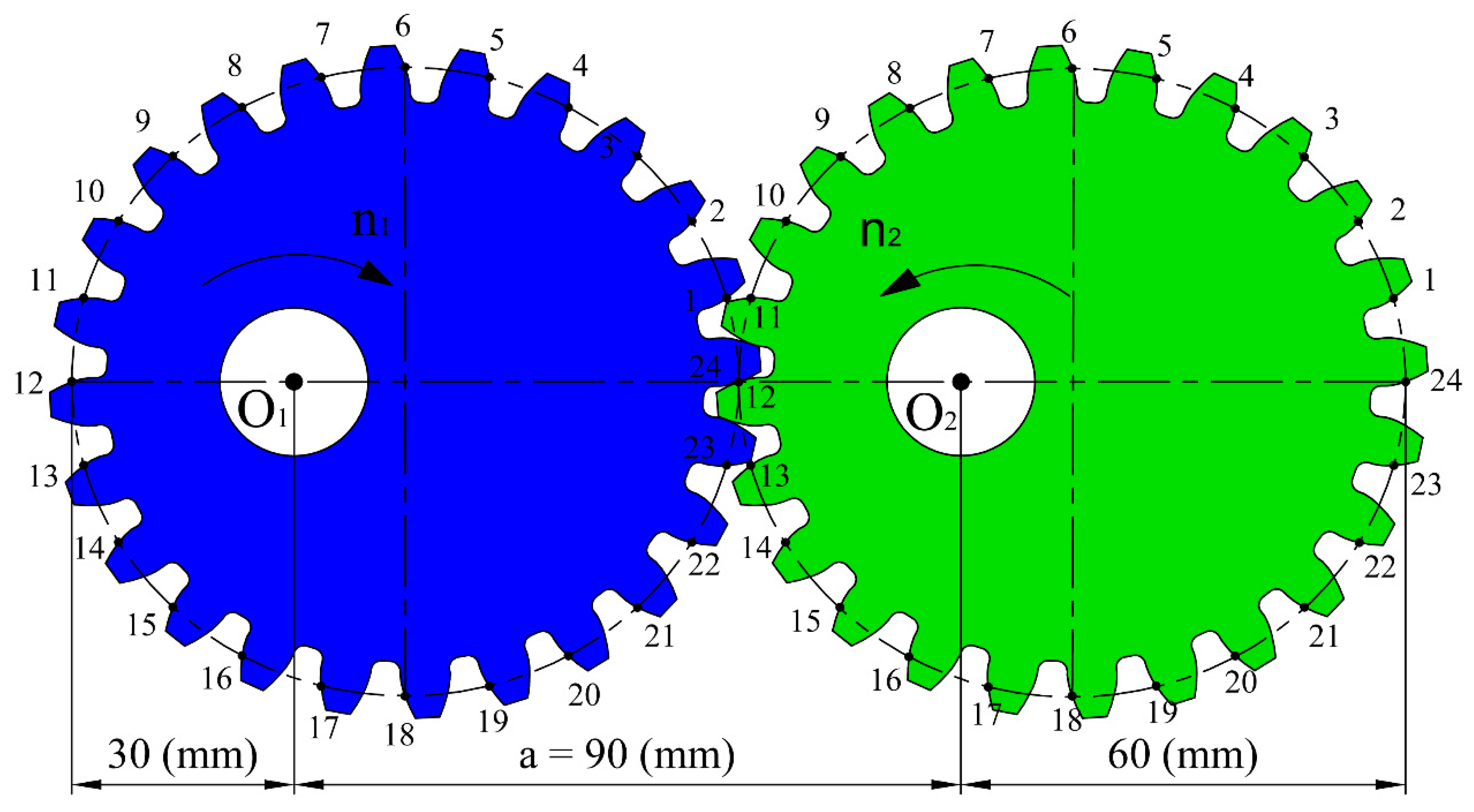
- the gear set had to be made up of two identical gears,
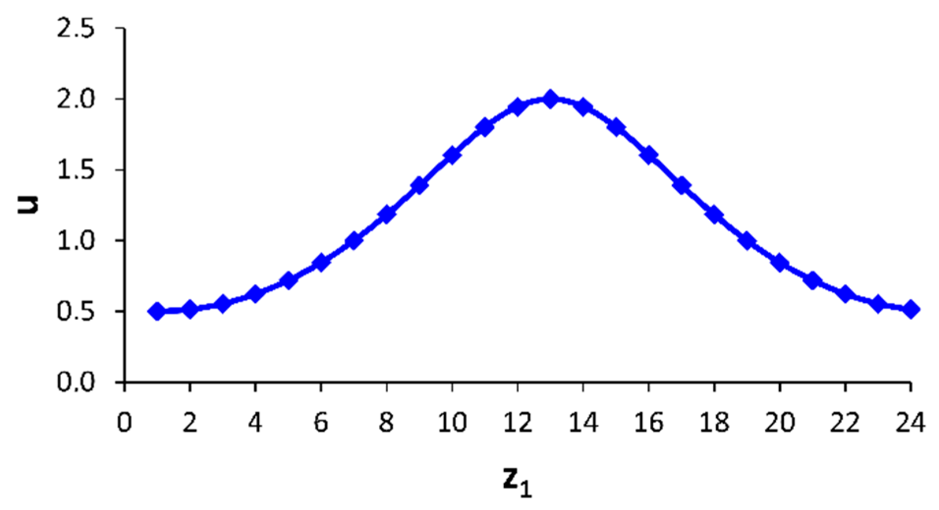
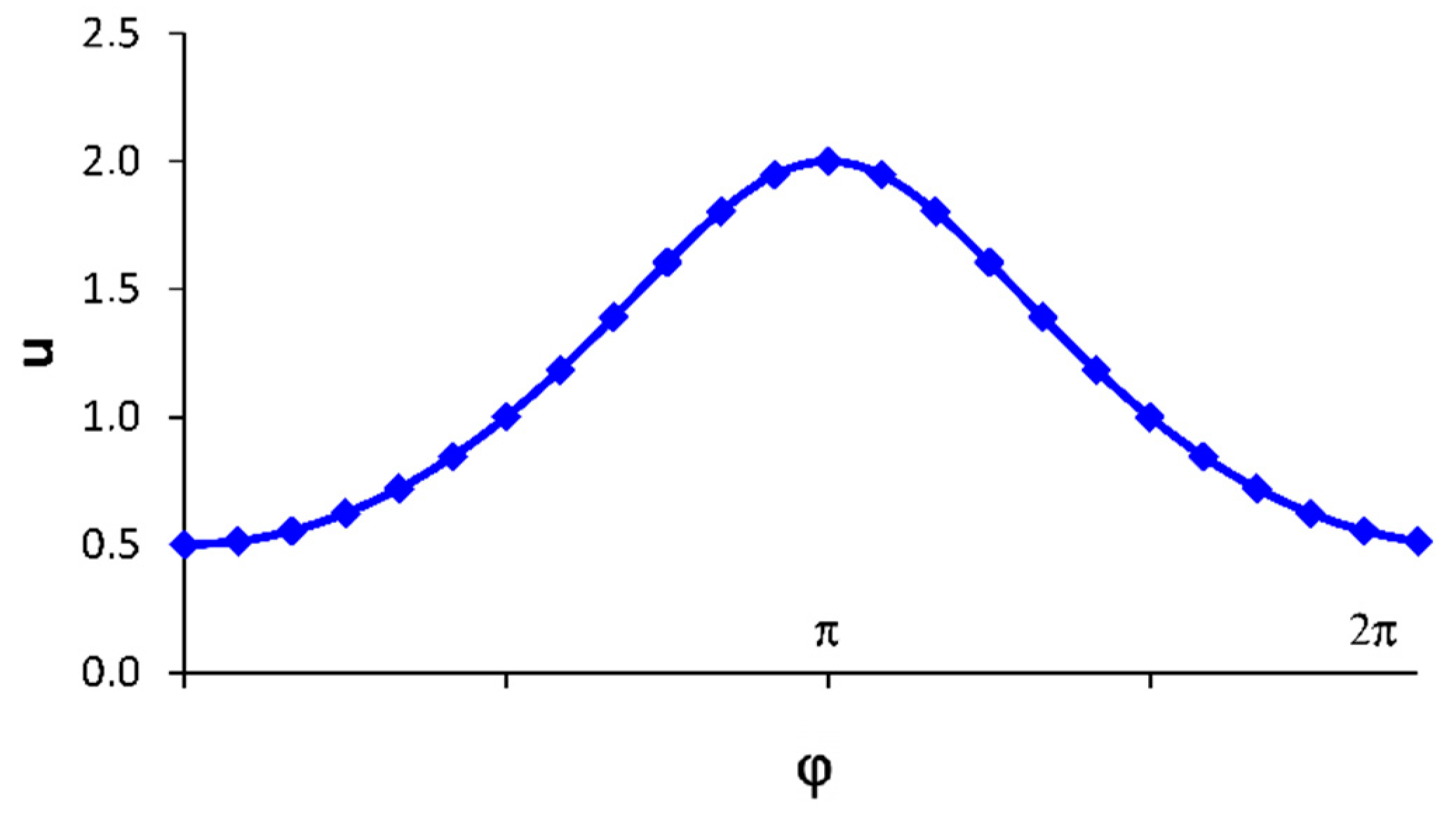
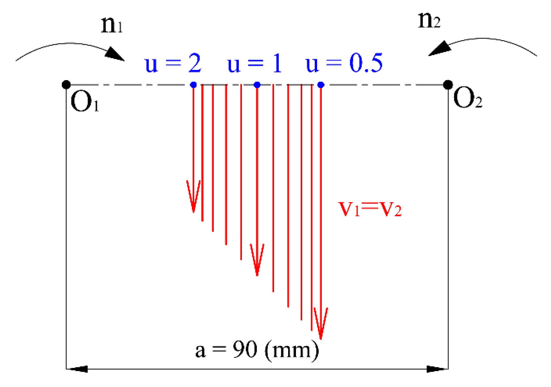
- the gear ratio has to change harmonically in the range from u = 0.5 through 1.0 to 2.0 and back during one revolution of the intermeshing gears,
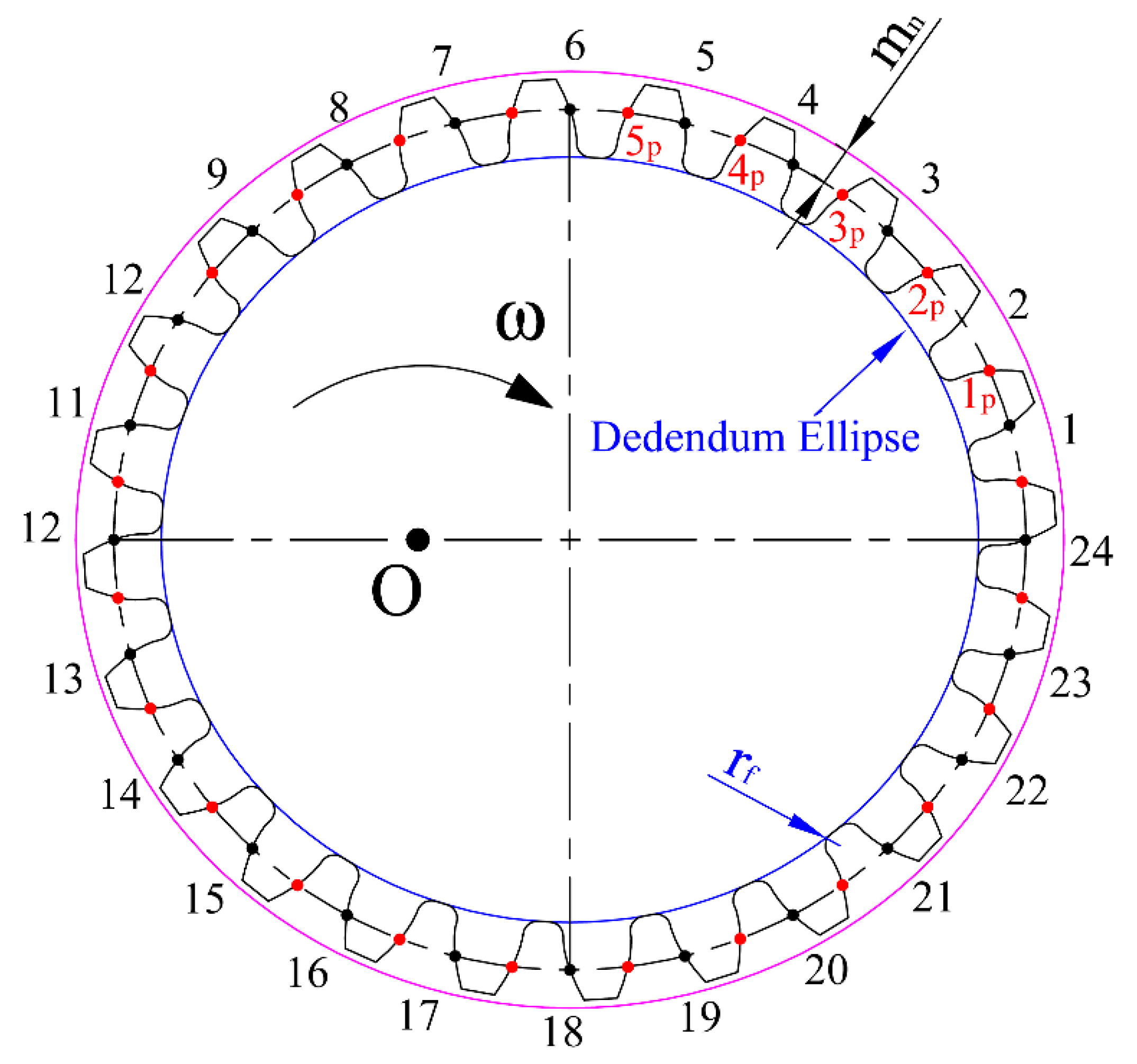
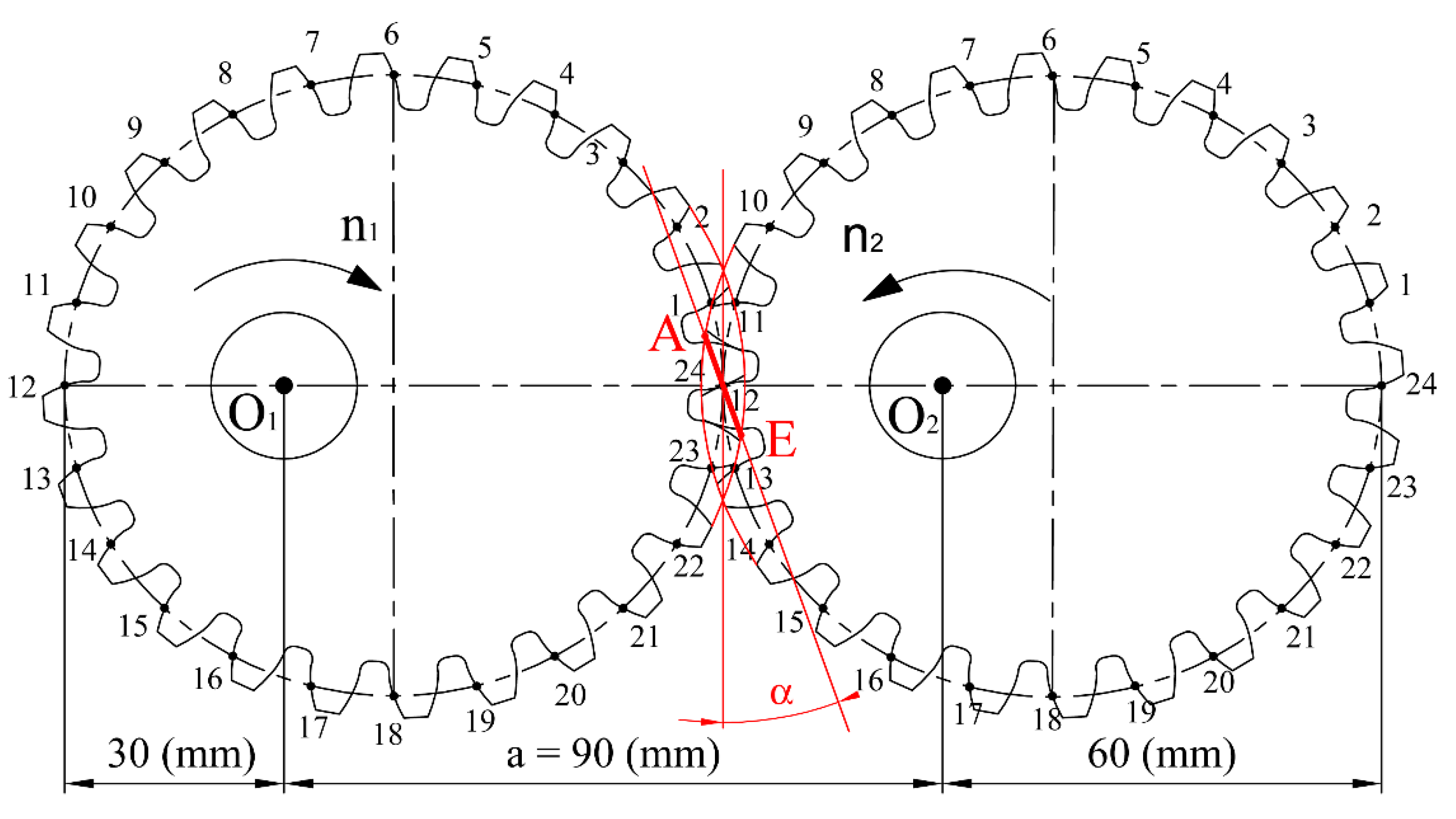
- the number of teeth of the gears z1 = z2 = 24,
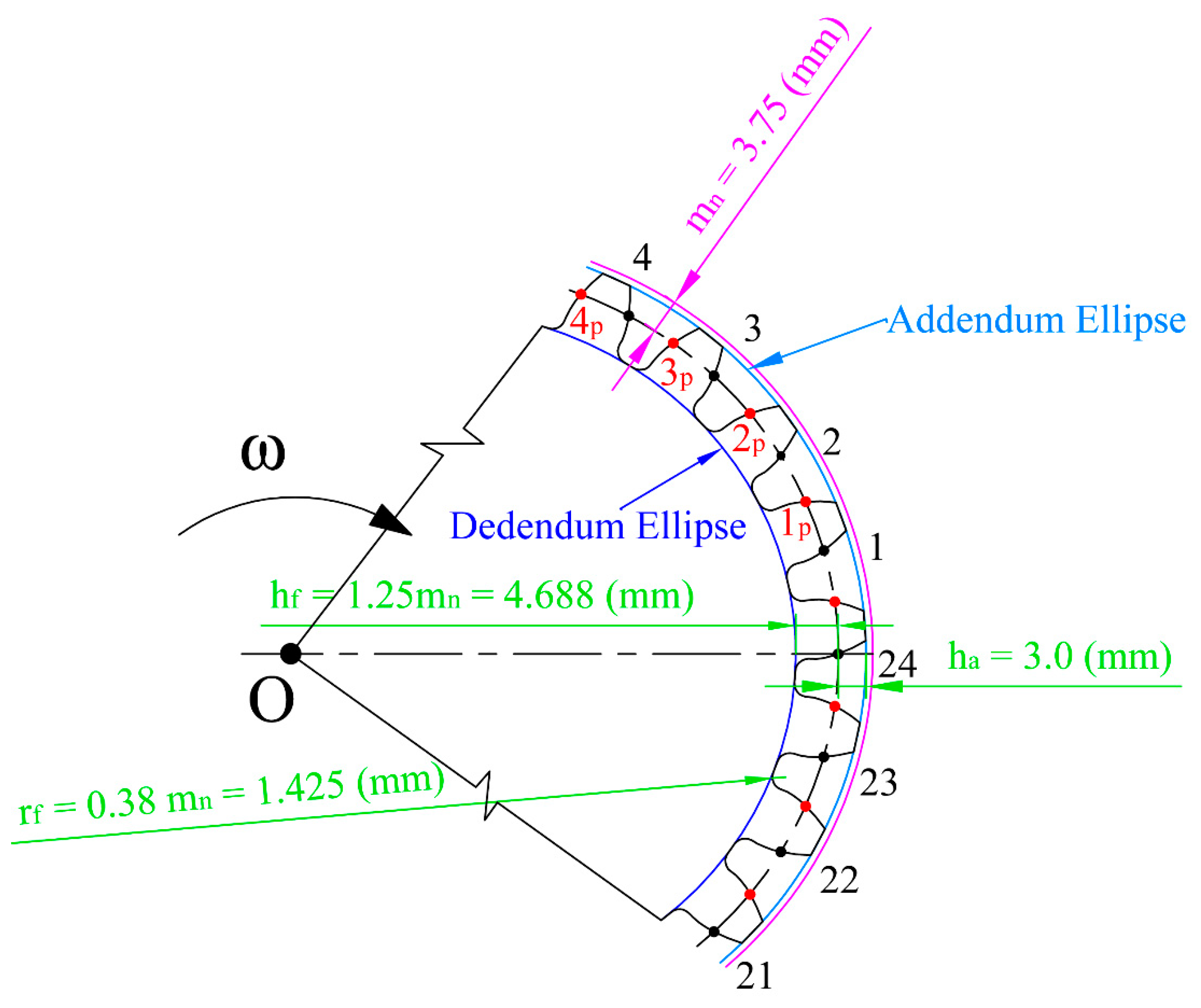
- the standardized value of the gearing module mn = 3.75 mm,
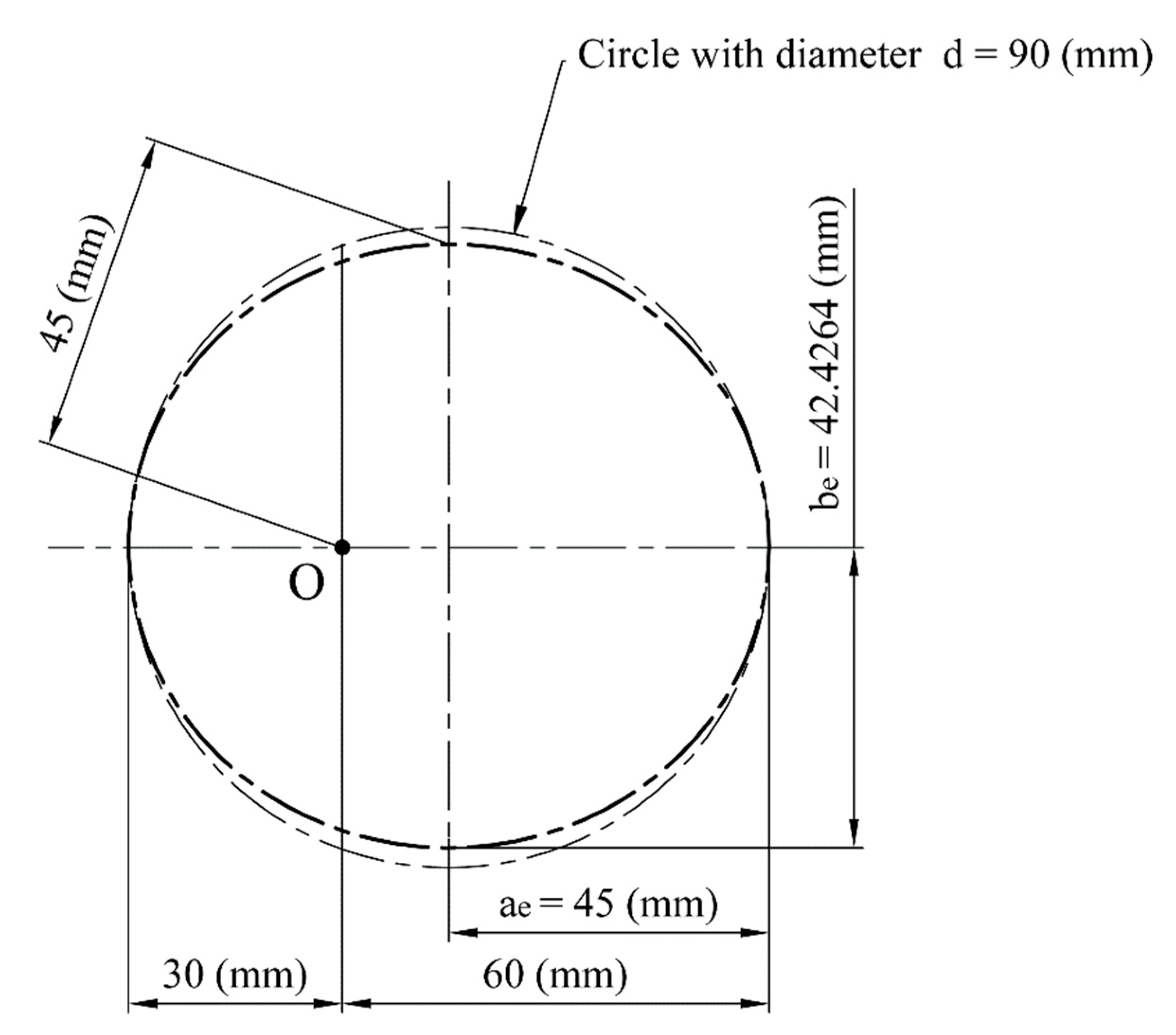
- the axial distance a = 90 mm,
- the pressure angles αn = 20°,
- intended for one sense of rotation.
2.2. Conditions of Correct Meshing of Gears
- The condition of common profile normal at each mesh point of intermeshing gears, which has to pass through the pitch point.
- The condition of mesh continuity, which means the condition of the existence of the mesh of two consecutive profiles. Providing that the pitches measured on both working circles of two intermeshing gears (for standard circular gears) are equal, this condition is fulfilled.
- The condition of the contact of teeth along the whole face width of a gearing. Providing that the helix angles on working circles are equal, this condition is fulfilled.
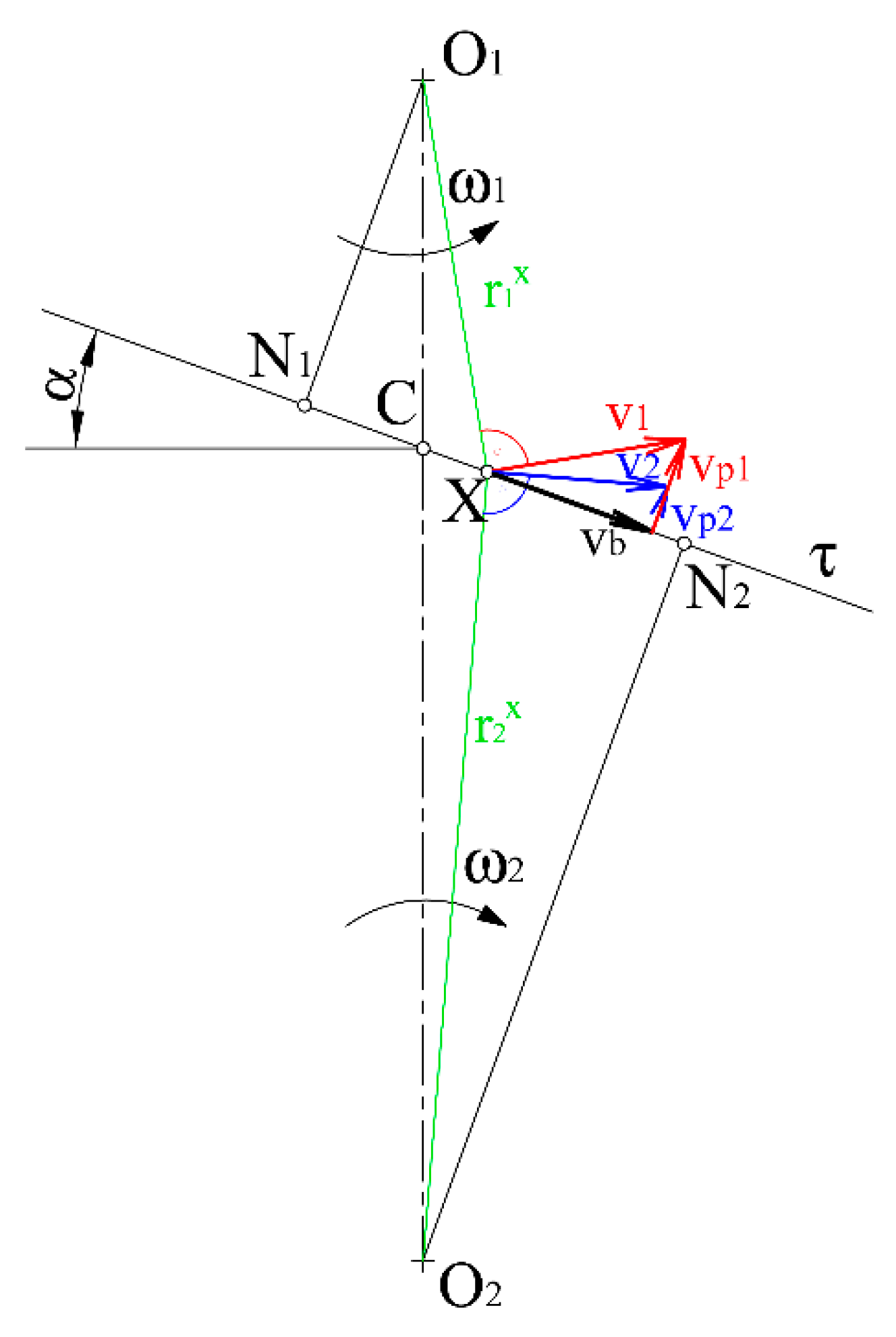
- The condition of circumferential velocities, which means the projections of circumferential velocities to the common profile normal have to be equal in each mesh point.
- The condition of working circle contact (the sum of the working radiuses of intermeshing gears in each mesh point equals the center distance).
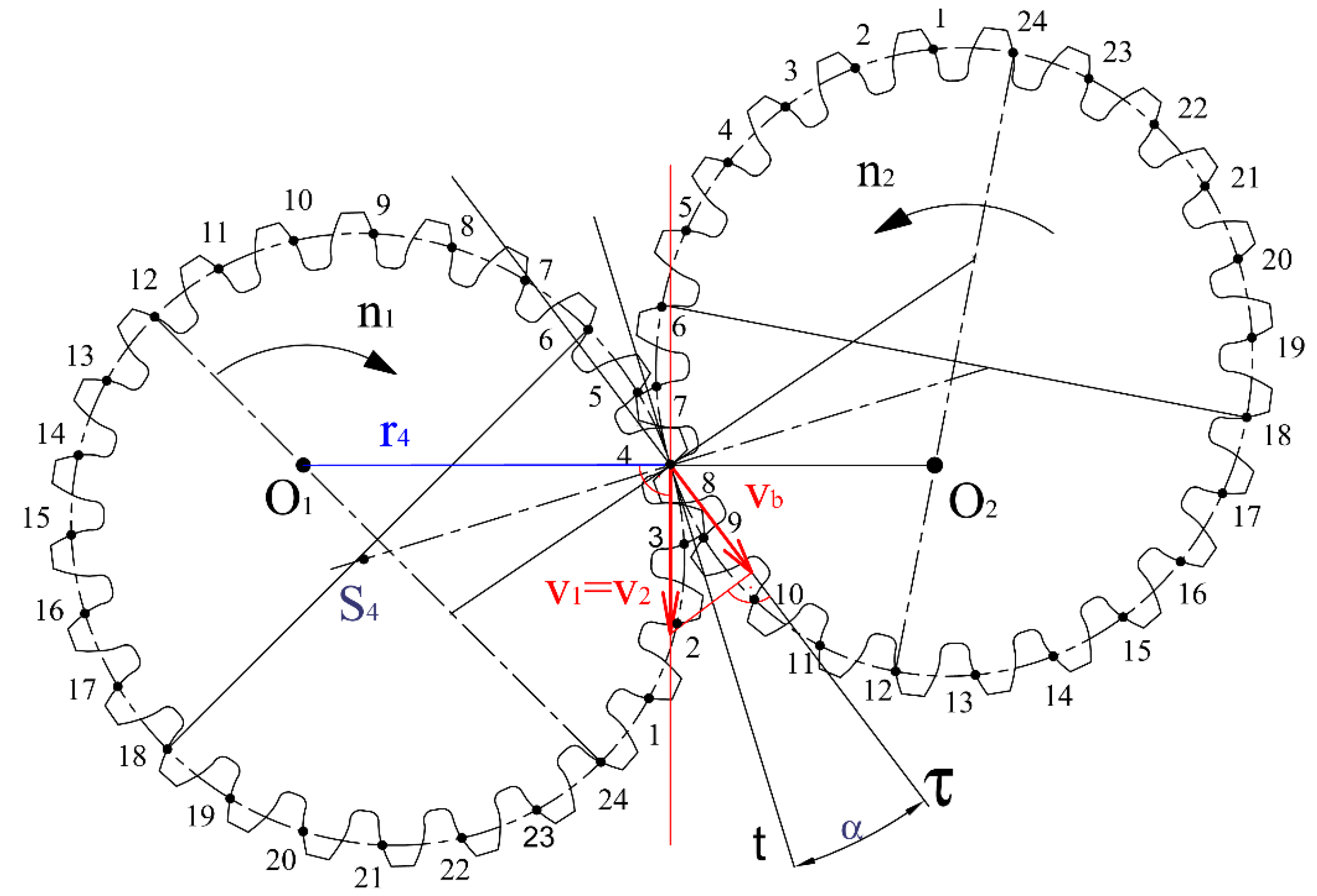
2.3. Velocity Relations in Ideal Intermeshing Spur Gears
3. Results and Discussion
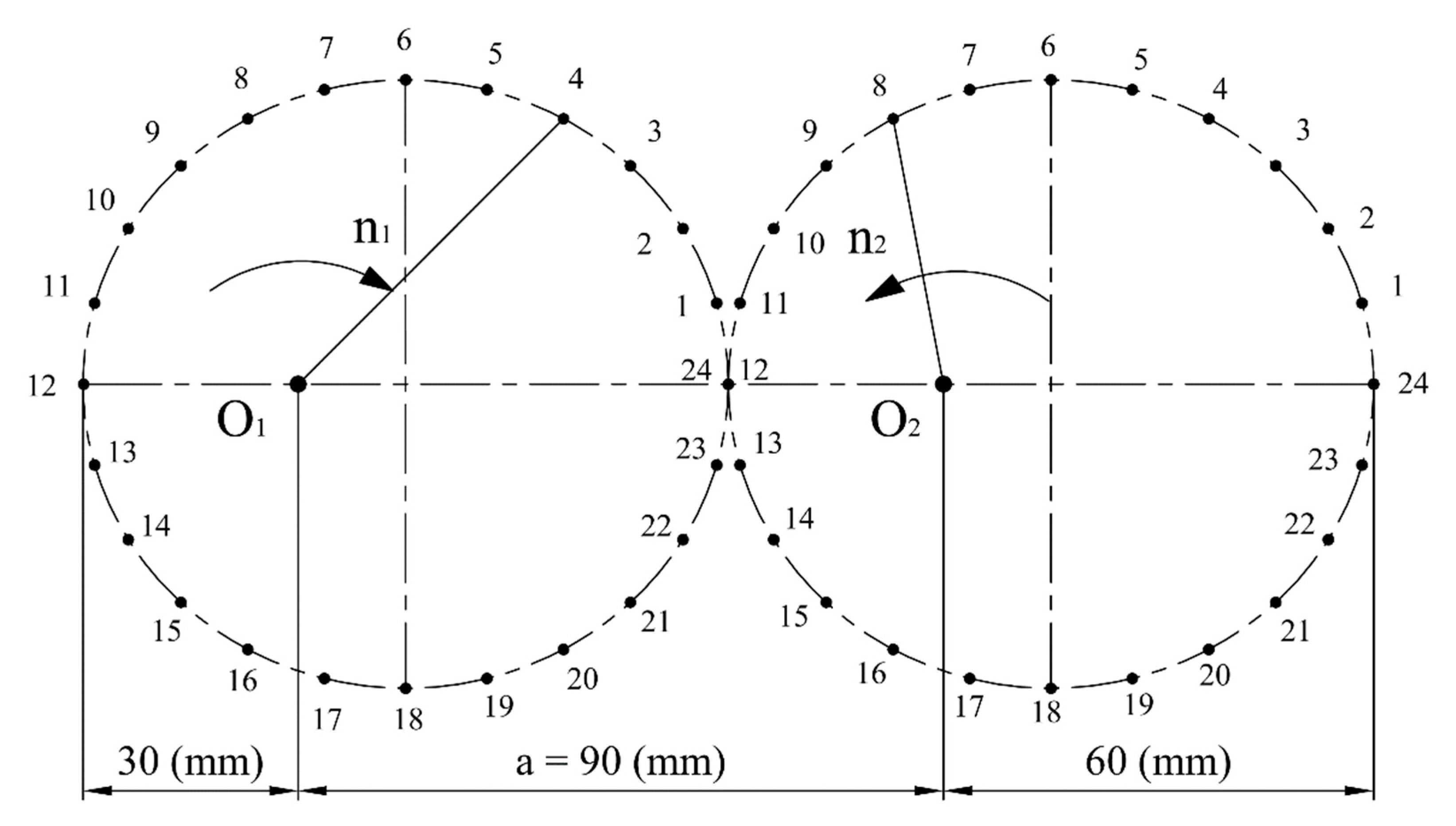
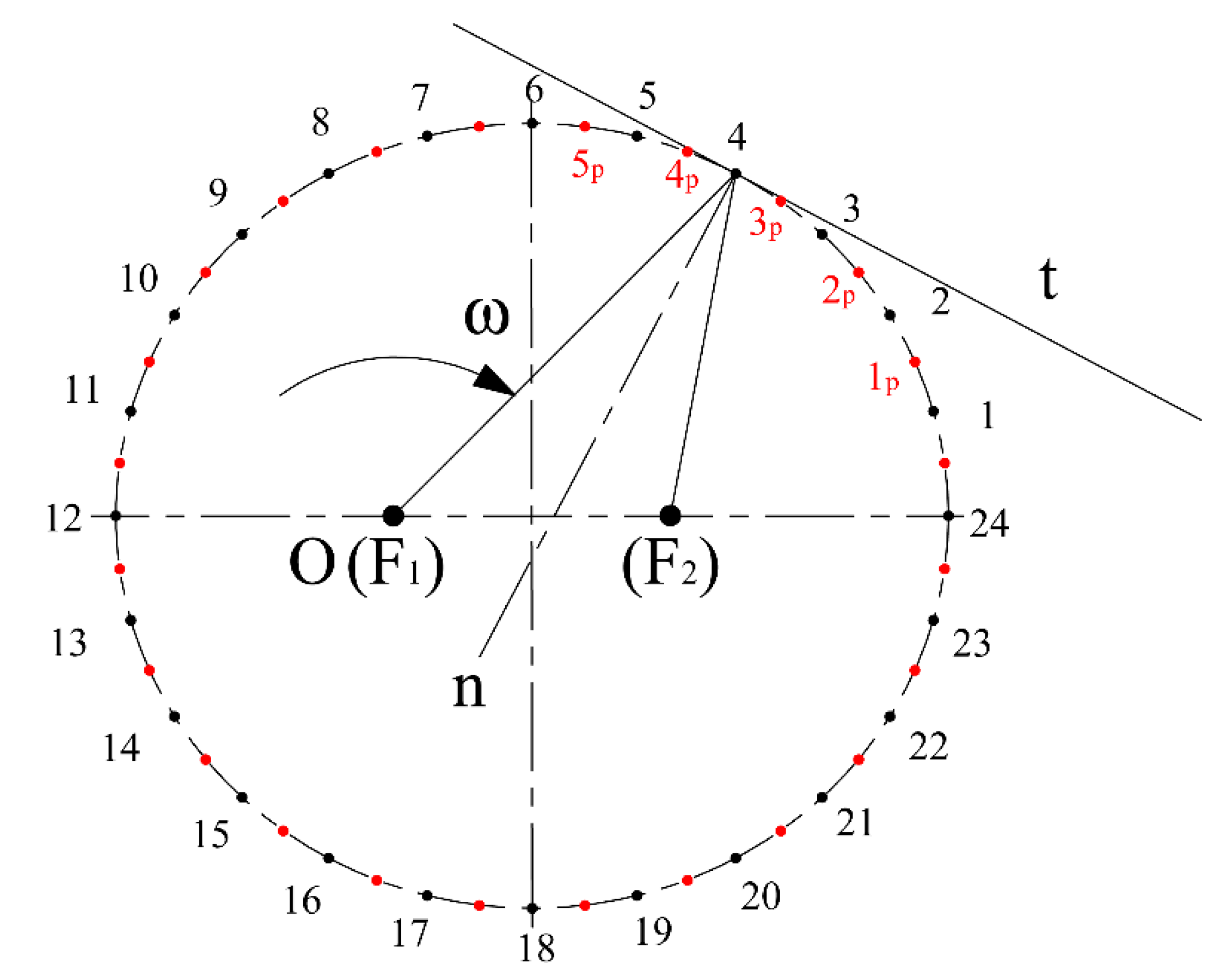
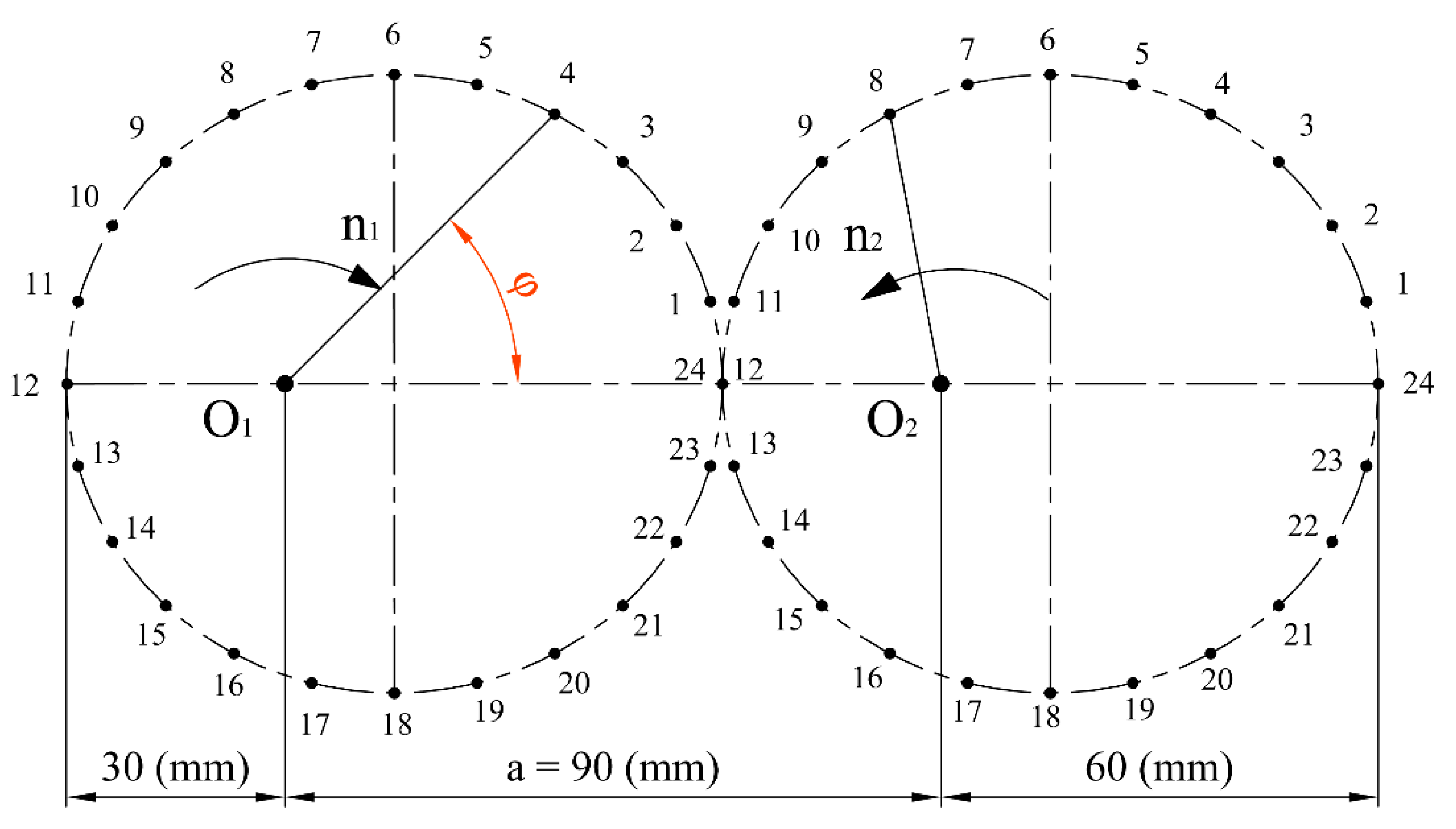
3.1. Design of the Pitch Curve Shape
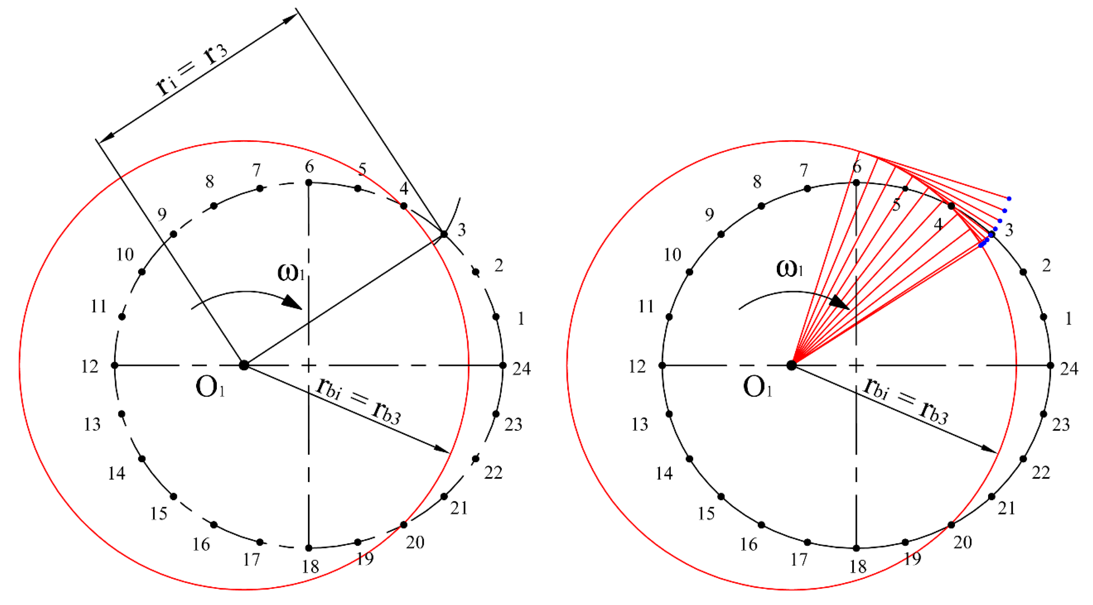
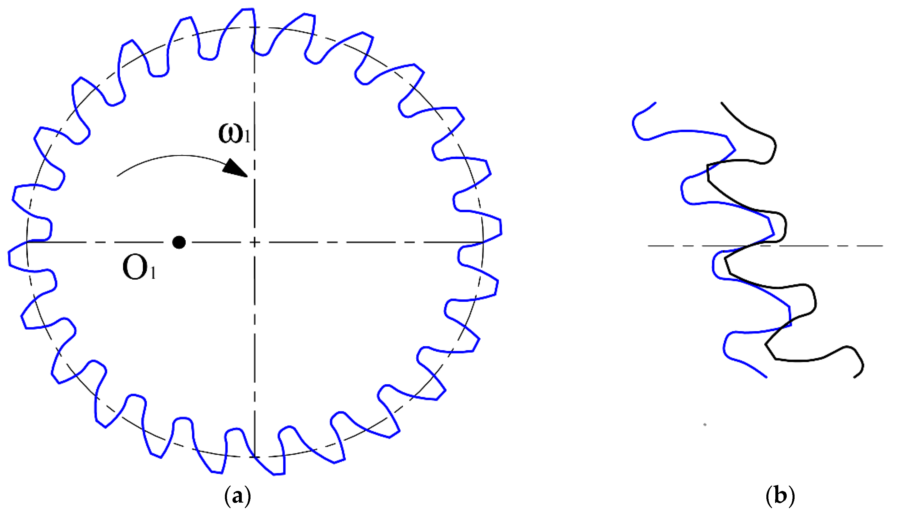
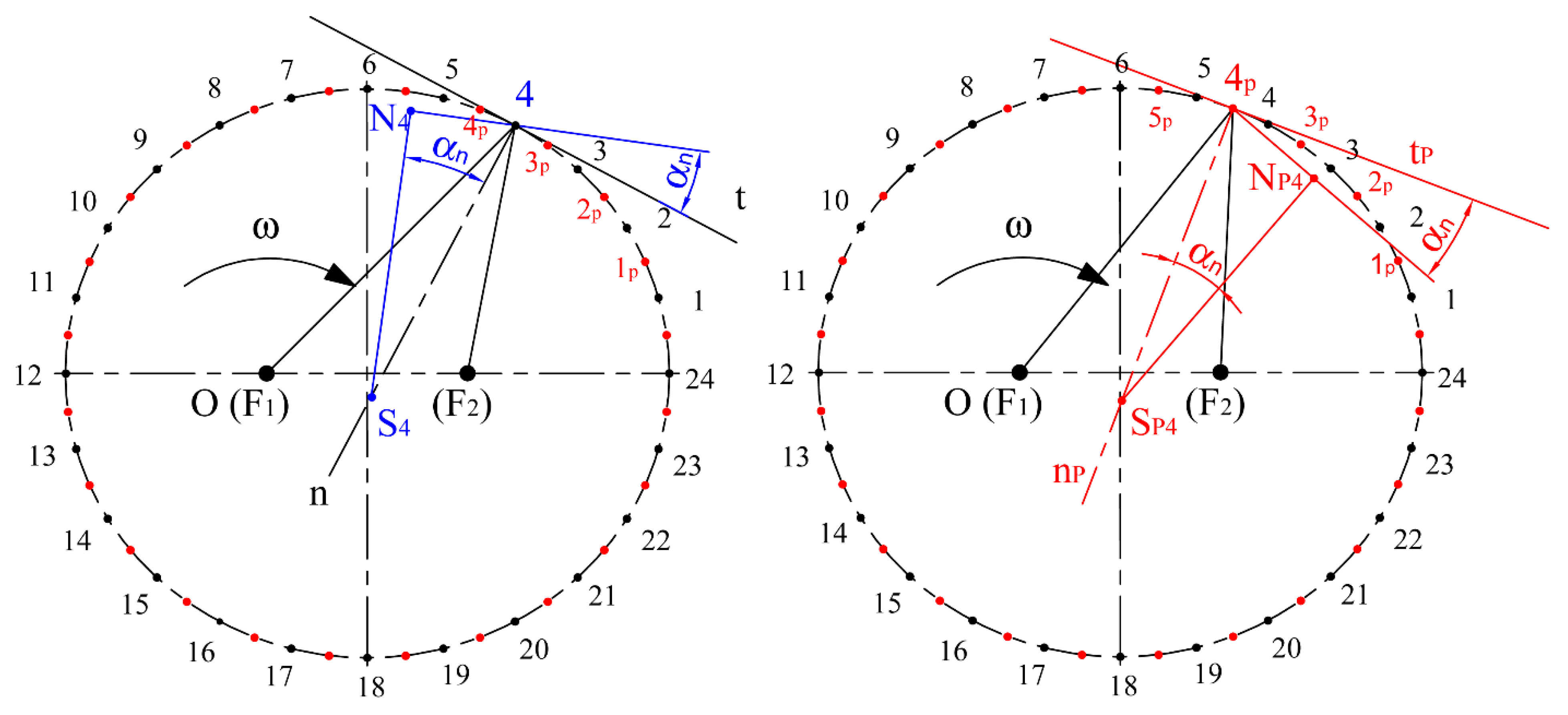
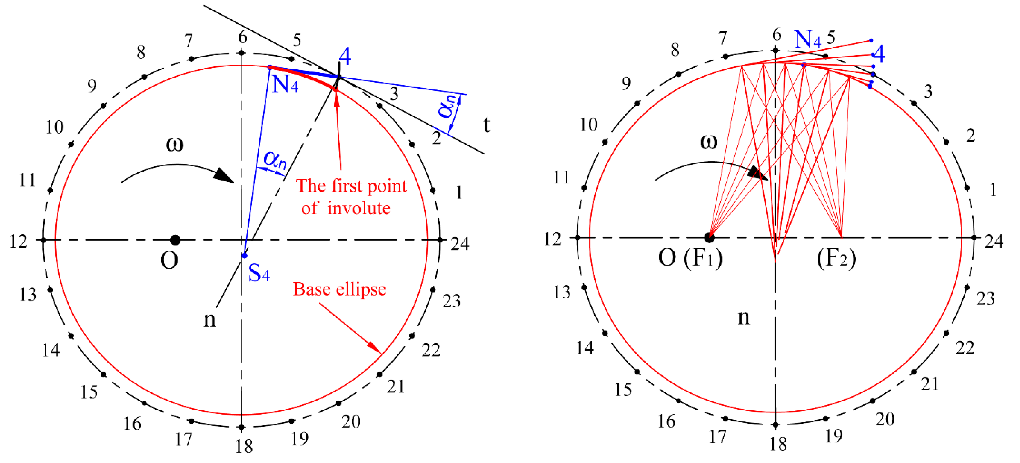
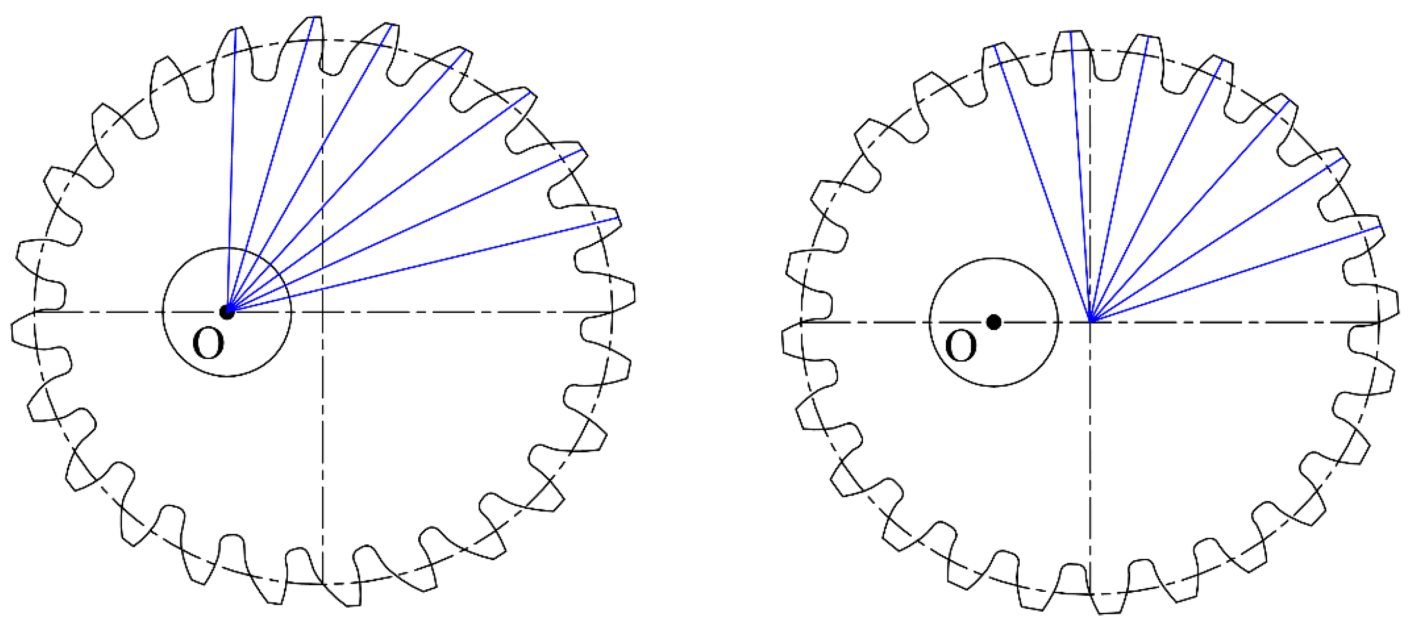
3.2. Creation of the Geometrical Model of the Elliptical Gear Set
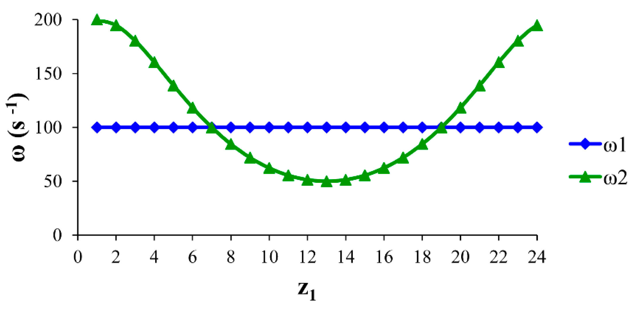
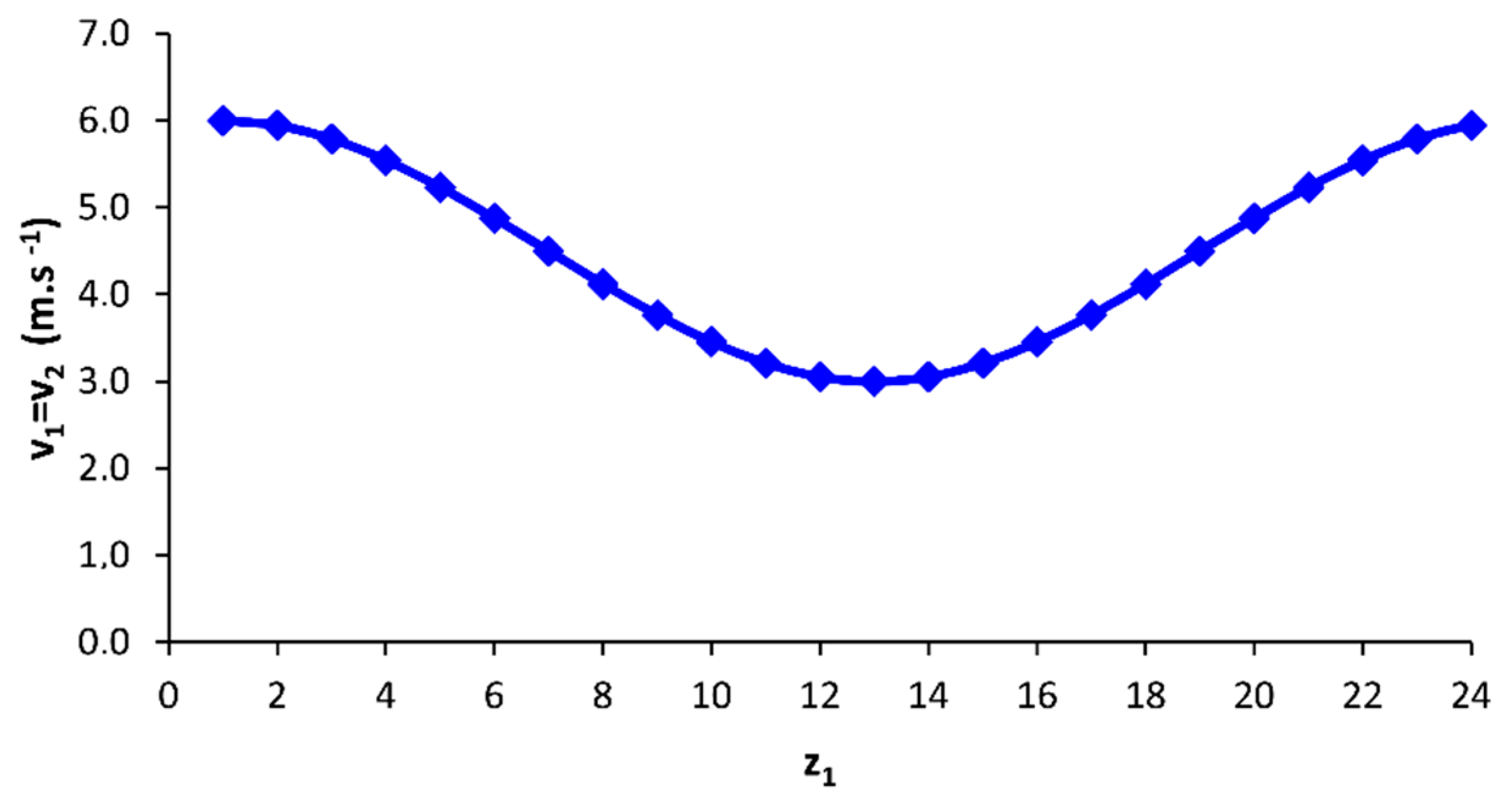
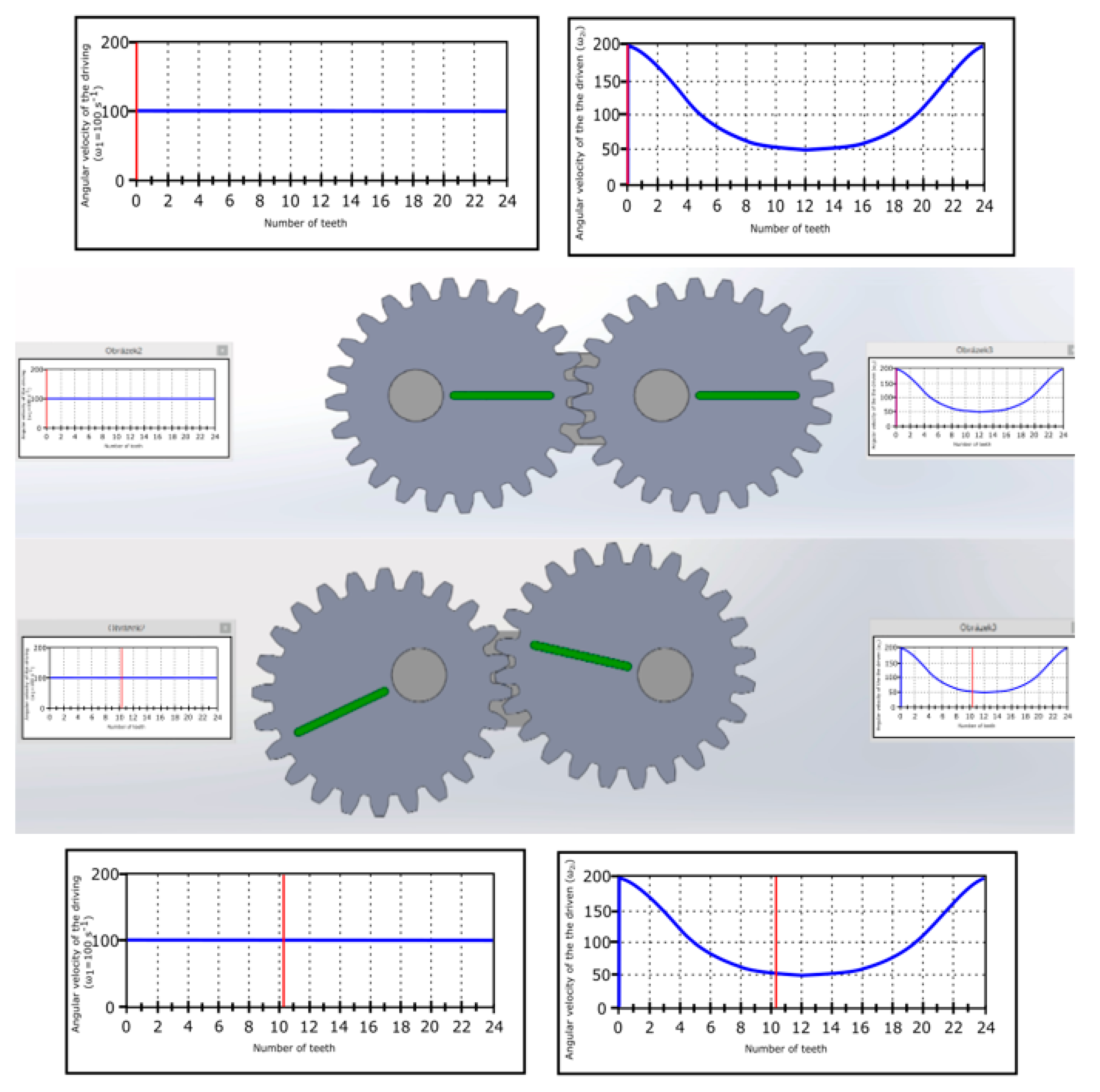
3.3. Velocity Relations in the Designed Elliptical Gear Set
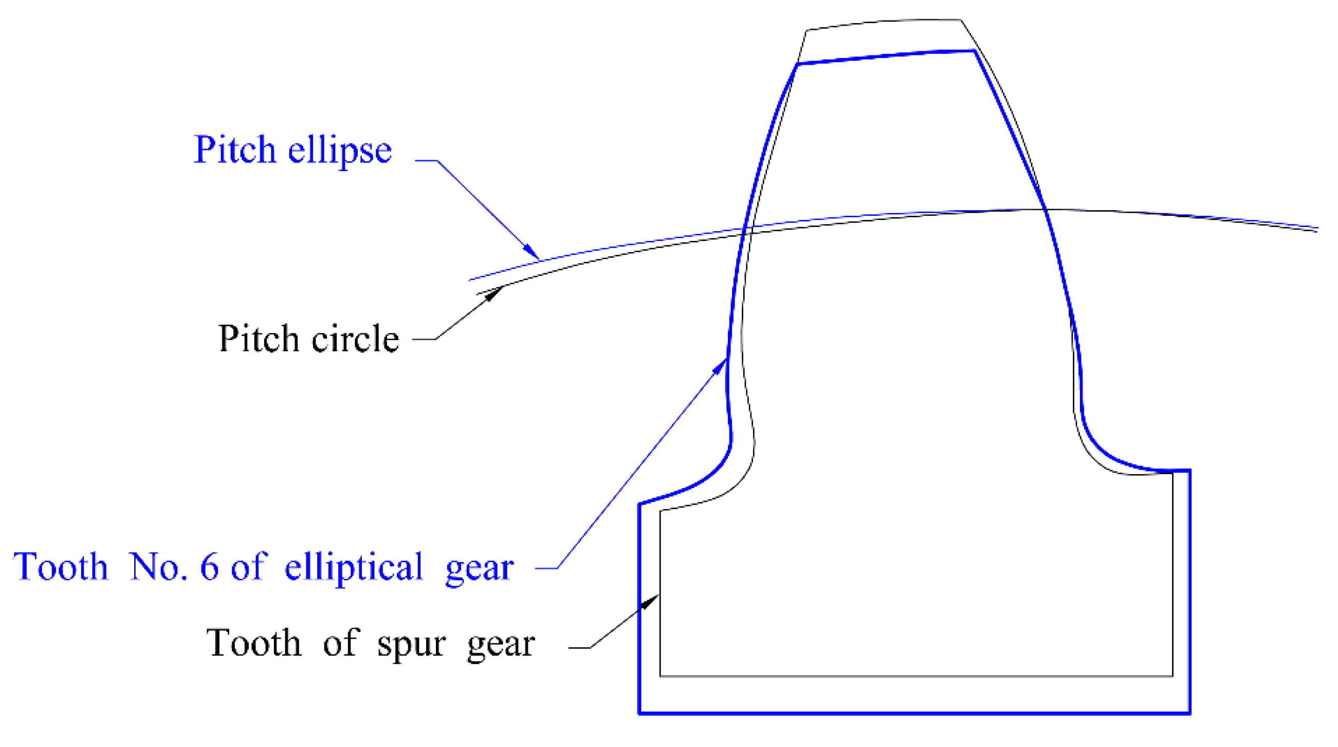
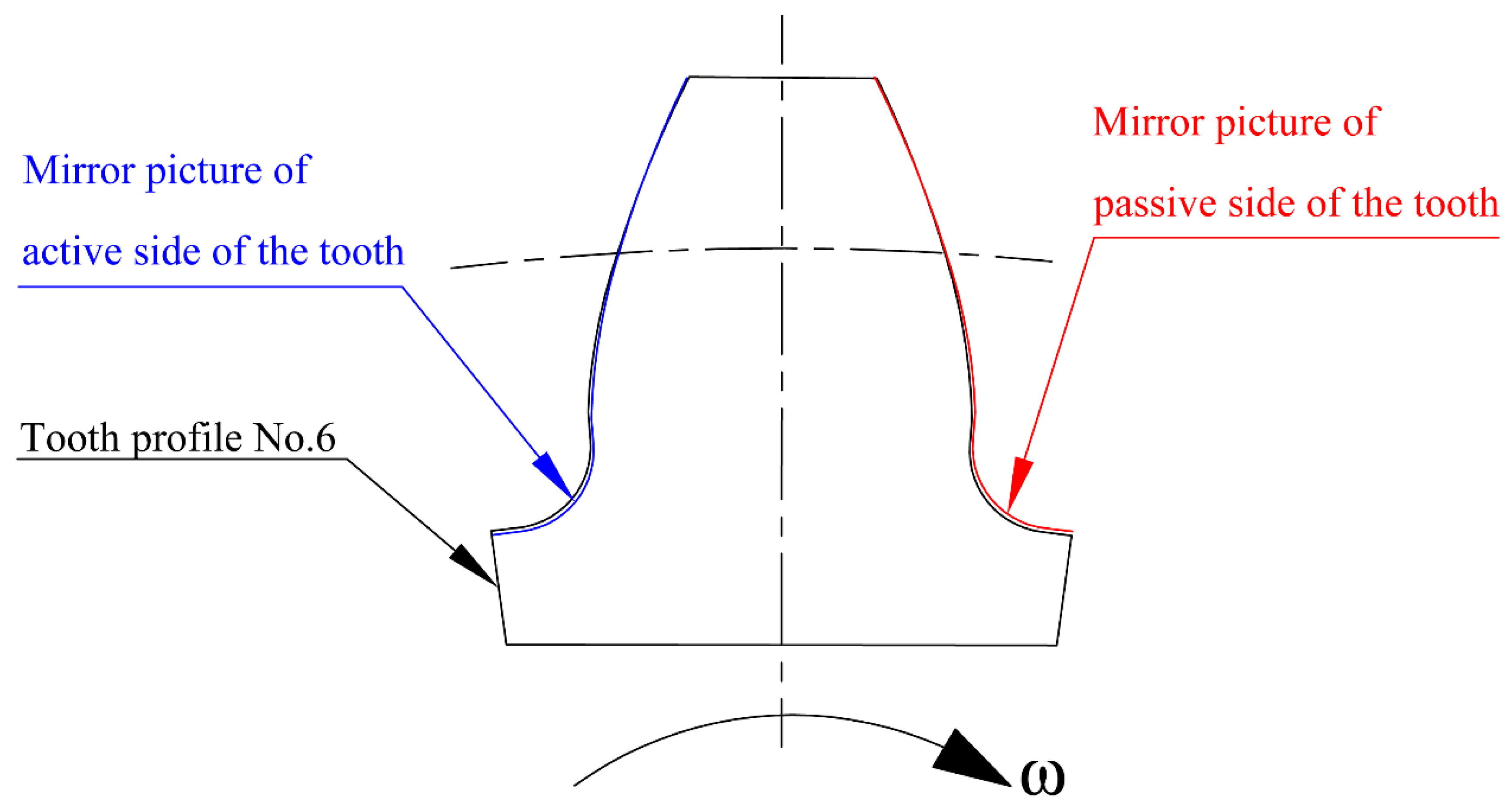
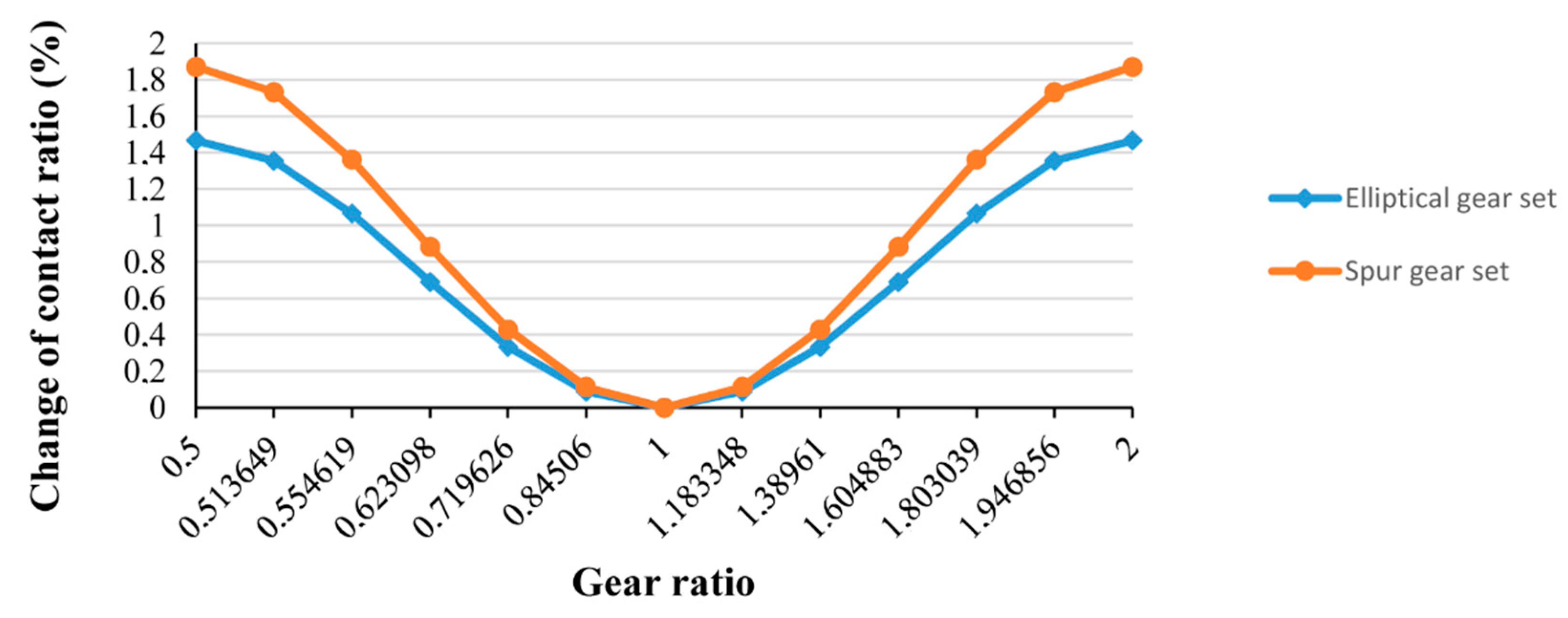
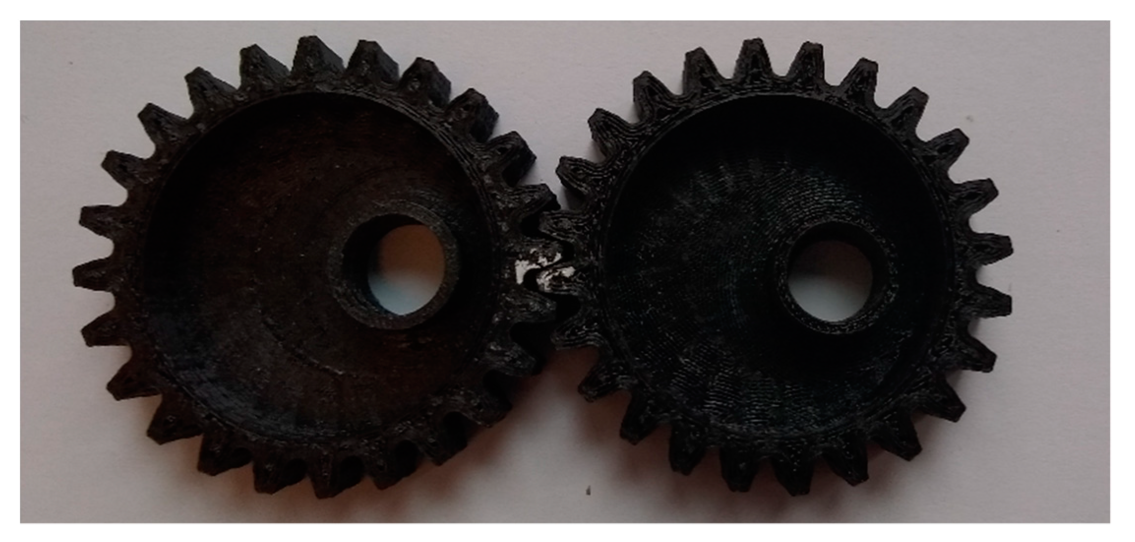
3.4. Verification of the Correctness of the Design of Elliptical Gearing
4. Conclusions
Author Contributions
Funding
Conflicts of Interest
References
- Lewis, M. Gearing in the ancient world. Endeavour 1993, 17, 110–115. [Google Scholar] [CrossRef]
- Zarebski, I.; Sałacinski, T. Designing of non-circular gears. Arch. Mech. Eng. 2008, LV., 275–292. [Google Scholar]
- Mundo, D. Geometric design of a planetary gear train with non-circular gears. Mech. Mach. Theory 2006, 41, 456–472. [Google Scholar] [CrossRef]
- Marimuthu, P.; Muthuveerappan, G. Design of asymmetric normal contact ratio spur gear drive through direct design to enhance the load carrying capacity. Mech. Mach. Theory 2016, 95, 22–34. [Google Scholar] [CrossRef]
- Chen, Y.-Z.; Huang, H.; Lv, Y. A variable-ratio line gear mechanism. Mech. Mach. Theory 2016, 98, 151–163. [Google Scholar] [CrossRef]
- Kowalczyk, L.; Urbanek, S. The geometry and kinematics of a toothed gear of variable motion. Fibres Text. East. Eur. 2003, 11, 60–62. [Google Scholar]
- Schmidt, M. Window shade with a shade panel. U.S. Patent 6,672,363, 6 January 2004. [Google Scholar]
- Litvin, F.L.; Gonzalez-Perez, I.; Fuentes, A.; Hayasaka, K. Design and investigation of gear drives with non-circular gears applied for speed variation and generation of functions. Comput. Methods Appl. Mech. Eng. 2008, 197, 3783–3802. [Google Scholar] [CrossRef]
- Lin, C.; Hou, Y.; Gong, H.; Liu, G.; Li, L. Design and analysis of transmission mode for high-order deformed elliptic bevel gears. Jixie Gongcheng Xuebao (Chin. J. Mech. Eng.) 2011, 47, 131–139. [Google Scholar] [CrossRef]
- Liu, D.; Ren, T.; Jin, X. Geometrical model and tooth analysis of undulating face gear. Mech. Mach. Theory 2015, 86, 140–155. [Google Scholar] [CrossRef]
- Bair, B.-W. Computer aided design of elliptical gears with circular-arc teeth. Mech. Mach. Theory 2004, 39, 153–168. [Google Scholar] [CrossRef]
- Okada, M.; Takeda, Y. Optimal design of nonlinear profile of gear ratio using non-circular gear for jumping robot. In Proceedings of the 2012 IEEE International Conference on Robotics and Automation, Saint Paul, MN, USA, 14–18 May 2012; pp. 1958–1963. [Google Scholar]
- Zhuang, W.; Hua, L.; Han, X.; Zheng, F. Design and hot forging manufacturing of non-circular spur bevel gear. Int. J. Mech. Sci. 2017, 133, 129–146. [Google Scholar] [CrossRef]
- Zheng, F.; Han, X.; Hua, L.; Zhang, M.; Zhang, W. Design and manufacture of new type of non-circular cylindrical gear generated by face-milling method. Mech. Mach. Theory 2018, 122, 326–346. [Google Scholar] [CrossRef]
- Shi, K.; Yao, Y.-A.; Lin, S. Design Method for N-Lobed Noncircular Bevel Gears. Adv. Mech. Eng. 2020, 12, 1687814019897498. [Google Scholar] [CrossRef]
- Yu, Y.; Liu, J.; Ye, B.; Yu, G.; Jin, X.; Sun, L.; Tong, J. Design and Experimental Research on Seedling Pick-Up Mechanism of Planetary Gear Train with Combined Non-circular Gear Transmission. Chin. J. Mech. Eng. 2019, 32, 49. [Google Scholar] [CrossRef]
- Li, M.; Shi, T.; Yang, J.; Qi, L.; Zhao, Z. Realizing nonlinear springs through noncircular planetary gears. Mech. Mach. Theory 2021, 156, 104151. [Google Scholar] [CrossRef]
- Hou, Y.; Lin, C. Kinematic analysis and experimental verification of an oval noncircular bevel gears with rotational and axial translational motions. J. Braz. Soc. Mech. Sci. Eng. 2019, 42, 60. [Google Scholar] [CrossRef]
- Prikhodko, A. Experimental kinematic analysis of an intermittent motion planetary mechanism with elliptical gears. J. Meas. Eng. 2020, 8, 122–131. [Google Scholar] [CrossRef]
- Sałaciński, T.; Przesmycki, A.; Chmielewski, T. Technological Aspects in Manufacturing of Non-Circular Gears. Appl. Sci. 2020, 10, 3420. [Google Scholar] [CrossRef]
- Radzevich, S.P. Dudley’s Handbook of Practical Gear Design and Manufacture; CRC Press: Boca Raton, FL, USA, 2012. [Google Scholar]
- Nemcek, M.; Dejl, Z. New method of a calculation of equidistant coordinates of an involute tooth profile for FEM calcula-tions of gears. In Proceedings of the ASME Design Engineering Technical Conference, San Diego, CA, USA, August 30–September 2 2009. [Google Scholar]
- Medvecká-Beňová, S. Meshing Condition and Kinematic Properties of non-circular Gear. Acta Mech. Slovaca 2016, 20, 16–21. [Google Scholar] [CrossRef]
- Tsai, S.-J.; Huang, G.-L.; Ye, S.-Y. Gear meshing analysis of planetary gear sets with a floating sun gear. Mech. Mach. Theory 2015, 84, 145–163. [Google Scholar] [CrossRef]
- Šalamoun, Č.; Suchý, M. Čelní a Šroubová souKolí s Evolventním Ozubením; SNTL: Praha, Slovakia, 1990. [Google Scholar]
- Laczik, B. Involute Profile of Non-Circular Gears. Inst. Mech. Eng. Coll. Dunaújváros 2004, 8, 1–5. [Google Scholar]
- Liu, D.; Ren, T. Creating pitch curve of closed noncircular gear by compensation method. Jixie Gongcheng Xuebao (Chin. J. Mech. Eng.) 2011, 47, 147–152. [Google Scholar] [CrossRef]
- Figlus, T.; Koziol, M.; Kuczynski, L. No Ti the Effect of Selected Operational Factors on the Vibroactivity of Upper Gearbox Housings Made of Composite Materials. Sensors 2019, 19, 4240. [Google Scholar] [CrossRef] [PubMed]
- Maláková, S. Kinematic properties and mesching condition of elliptical gear train. Sci. J. Sil. Univ. Technol. Transp. 2019, 104, 95–105. [Google Scholar]
- Dooner, D.B. Kinematic Geometry of Gearing; Wiley: Hoboken, NJ, USA, 2012; ISBN 9781119950943. [Google Scholar]
- Meneses, J.; Garciaprada, J.C.; Castejon, C.; Rubio, H.; Abad, E.C. The kinematics of the rotary into helical gear transmission. Mech. Mach. Theory 2017, 108, 110–122. [Google Scholar] [CrossRef]
- Bair, B.-W. Computer aided design of non-standard elliptical gear drives. Proc. Inst. Mech. Eng. Part C J. Mech. Eng. Sci. 2001, 216, 473–482. [Google Scholar] [CrossRef]
- Kosters, M. Curvature-dependent parameterization of curves and surfaces. Comput. Des. 1991, 23, 569–578. [Google Scholar] [CrossRef]
- Schubert, P.; Kirchner, M. Ellipse area calculations and their applicability in posturography. Gait Posture 2014, 39, 518–522. [Google Scholar] [CrossRef]
- Tsay, C.-B.; Liu, W.-Y.; Chen, Y.-C. Spur gear generation by shaper cutters. J. Mater. Process. Technol. 2000, 104, 271–279. [Google Scholar] [CrossRef][Green Version]
- Figliolini, G.; Angeles, J. The Synthesis of Elliptical Gears Generated by Shaper-Cutters. J. Mech. Des. 2003, 125, 793–801. [Google Scholar] [CrossRef]
- Litvin, F.L.; Lian, Q.; Kapelevich, A.L. Asymmetric modified spur gear drives: Reduction of noise, localization of contact, simulation of meshing and stress analysis. Comput. Methods Appl. Mech. Eng. 2000, 188, 363–390. [Google Scholar] [CrossRef]
- Slovak National Standard STN 01 4686 Strength Calculation of Gears. 1975. Available online: http://www.visitsingapore.com/en_au/editorials/singapore-off-the-beaten-track-neighborhoods.html (accessed on 20 November 2017).
- Xia, L.; Li, D.Z.; Han, J. Research on Mathematical Modeling and Kinematic Simulation of Elliptic Family Gears. In Key Engineering Materials; Trans Tech Publications Ltd.: Freienbach, Switzerland, 2013; pp. 300–304. [Google Scholar] [CrossRef]


| Tooth of Driving Gear—Order Number | Pitch Radius r1-i (mm) | Tooth of Driven Gear—Order Number | Pitch Radius r2-j (mm) | Gear Ratio ui = r2-j/r1-i | Axial Distance r1-I + r2-j (mm) |
|---|---|---|---|---|---|
| 24 | 60 | 12 | 30 | 0.5 | 90 |
| 01 | 59.458972 | 11 | 30.541025 | 0.5136 | 90 |
| 02 | 57.891981 | 10 | 32.108009 | 0.5546 | 90 |
| 03 | 55.449504 | 09 | 34.550498 | 0.6230 | 90 |
| 04 | 52.336954 | 08 | 37.663046 | 0.7196 | 90 |
| 05 | 48.778898 | 07 | 41.221102 | 0.8450 | 90 |
| 06 | 45 | 06 | 45 | 1 | 90 |
| 07 | 41.221102 | 05 | 48.778898 | 1.1833 | 90 |
| 08 | 37.663046 | 04 | 52.336954 | 1.3896 | 90 |
| 09 | 34.550498 | 03 | 55.449504 | 1.6048 | 90 |
| 10 | 32.108009 | 02 | 57.891981 | 1.8030 | 90 |
| 11 | 30.541025 | 01 | 59.458972 | 1.9468 | 90 |
| 12 | 30 | 24 | 60 | 2 | 90 |
| 13 | 30.541025 | 23 | 59.458972 | 1.9468 | 90 |
| 14 | 32.108009 | 22 | 57.891981 | 1.8030 | 90 |
| 15 | 34.550498 | 21 | 55.449504 | 1.6048 | 90 |
| 16 | 37.663046 | 20 | 52.336954 | 1.3896 | 90 |
| 17 | 41.221102 | 19 | 48.778898 | 1.1833 | 90 |
| 18 | 45 | 18 | 45 | 1 | 90 |
| 19 | 48.778898 | 17 | 41.221102 | 0.8450 | 90 |
| 20 | 52.336954 | 16 | 37.663046 | 0.7196 | 90 |
| 21 | 55.449504 | 15 | 34.550498 | 0.6230 | 90 |
| 22 | 57.891981 | 14 | 32.108009 | 0.5546 | 90 |
| 23 | 59.458972 | 13 | 30.541025 | 0.5136 | 90 |
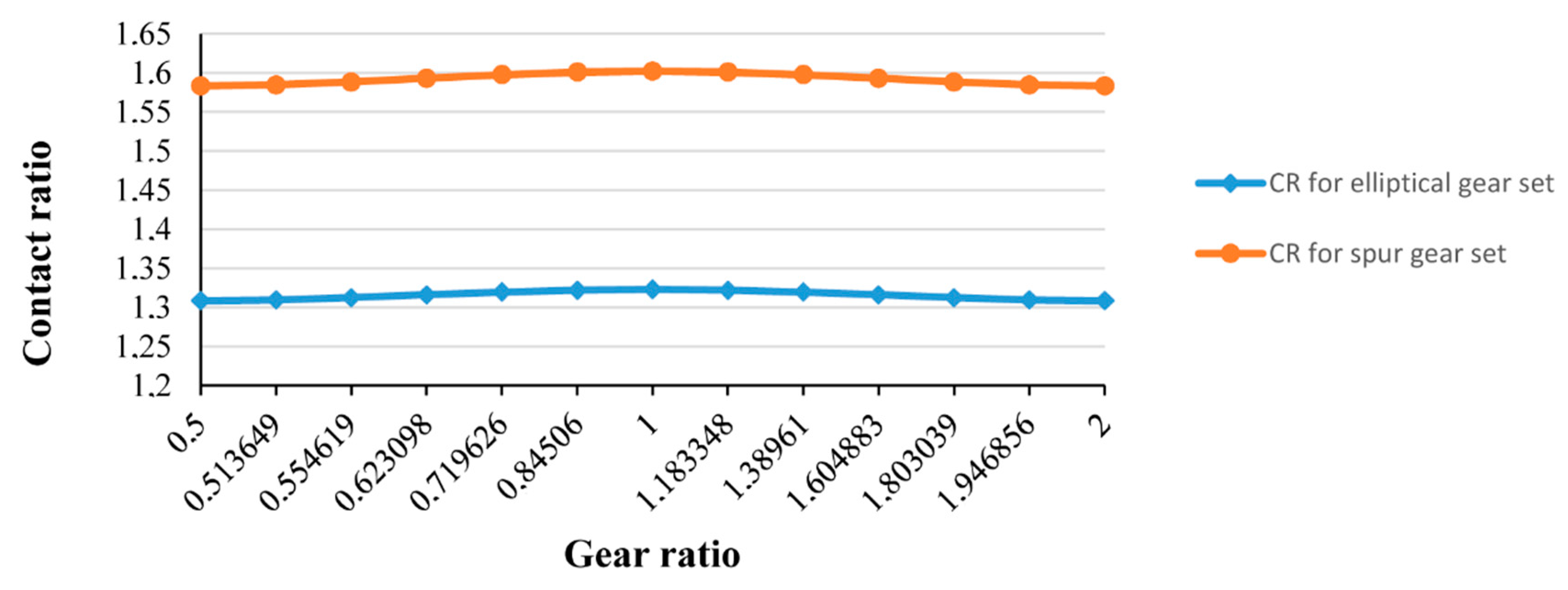
| Elliptical Gearing | Gear Ratio ui = r-j/r1-i | Spur Gearing (mn = 3.75 mm) | ||||
|---|---|---|---|---|---|---|
| AE (mm) | CR | Pitch Radius r1-i (mm) | Pitch Radius r2-j (mm) | AE (mm) | CR | |
| 14.482 | 1.3081 | 0.5 | 60 | 30 | 17.527 | 1.5832 |
| 14.494 | 1.3092 | 0.5136 | 59.458 | 30.541 | 17.542 | 1.5845 |
| 14.526 | 1.3122 | 0.5546 | 57.891 | 32.108 | 17.583 | 1.5883 |
| 14.568 | 1.3159 | 0.6230 | 55.449 | 34.550 | 17.636 | 1.5931 |
| 14.607 | 1.3195 | 0.7196 | 52.338 | 37.663 | 17.686 | 1.5976 |
| 14.634 | 1.3219 | 0.8450 | 48.779 | 41.221 | 17.721 | 1.6001 |
| 14.644 | 1.3228 | 1.0 | 45 | 45 | 17.733 | 1.6002 |
| 14.634 | 1.3219 | 1.1833 | 41.221 | 48.779 | 17.721 | 1.6001 |
| 14.607 | 1.3195 | 1.3896 | 37.663 | 52.338 | 17.686 | 1.5976 |
| 14.568 | 1.3159 | 1.6049 | 34.550 | 55.449 | 17.636 | 1.5931 |
| 14.526 | 1.3122 | 1.8030 | 32.108 | 57.891 | 17.583 | 1.5883 |
| 14.494 | 1.3092 | 2.0 | 30.541 | 59.458 | 17.542 | 1.5845 |
Publisher’s Note: MDPI stays neutral with regard to jurisdictional claims in published maps and institutional affiliations. |
© 2021 by the authors. Licensee MDPI, Basel, Switzerland. This article is an open access article distributed under the terms and conditions of the Creative Commons Attribution (CC BY) license (http://creativecommons.org/licenses/by/4.0/).
Share and Cite
Maláková, S.; Urbanský, M.; Fedorko, G.; Molnár, V.; Sivak, S. Design of Geometrical Parameters and Kinematical Characteristics of a Non-circular Gear Transmission for Given Parameters. Appl. Sci. 2021, 11, 1000. https://doi.org/10.3390/app11031000
Maláková S, Urbanský M, Fedorko G, Molnár V, Sivak S. Design of Geometrical Parameters and Kinematical Characteristics of a Non-circular Gear Transmission for Given Parameters. Applied Sciences. 2021; 11(3):1000. https://doi.org/10.3390/app11031000
Chicago/Turabian StyleMaláková, Silvia, Matej Urbanský, Gabriel Fedorko, Vieroslav Molnár, and Samuel Sivak. 2021. "Design of Geometrical Parameters and Kinematical Characteristics of a Non-circular Gear Transmission for Given Parameters" Applied Sciences 11, no. 3: 1000. https://doi.org/10.3390/app11031000
APA StyleMaláková, S., Urbanský, M., Fedorko, G., Molnár, V., & Sivak, S. (2021). Design of Geometrical Parameters and Kinematical Characteristics of a Non-circular Gear Transmission for Given Parameters. Applied Sciences, 11(3), 1000. https://doi.org/10.3390/app11031000