Article

Gear Shift Coordinated Control Strategy Based on Motor Rotary Velocity Regulation for a Novel Hybrid Electric Vehicle

Beijing Key Laboratory of Powertrain Technology for New Energy Vehicles, School of Mechanical, Electronic and Control Engineering, Beijing Jiaotong University, Beijing 100044, China
*
Author to whom correspondence should be addressed.
Appl. Sci. 2021, 11(24), 12118; https://doi.org/10.3390/app112412118
Submission received: 27 October 2021 / Revised: 23 November 2021 / Accepted: 29 November 2021 / Published: 20 December 2021

Abstract

:
This paper proposes a novel hybrid power system to improve the shift quality of a hybrid electric vehicle (HEV). After selecting a typical shift scheme, the study focused on the motor rotary velocity control algorithm and coordinated control strategy for the motor and clutch. The effects of various control algorithms on different target rotary velocities were analyzed, and a proportional-integral-derivative (PID)–bang-bang–fuzzy compound intelligent algorithm for a motor rotary velocity control system was investigated. In addition, to address the problems of the long synchronizing time required for the rotary velocity and large sliding friction work, which affect the shift quality during the process of engaging the clutch, a coordinated control strategy for the motor rotary velocity and clutch oil pressure was investigated. The research results showed that, compared with a gear shift coordinated control strategy based on a PID control algorithm, the strategy based on the PID–bang-bang–fuzzy compound intelligent control algorithm proposed here reduced the shift time and clutch slipping friction work by 35.7% and 19.2%, respectively.

1. Introduction

Hybrid electric vehicles (HEVs) have a variety of driving modes that can effectively improve the vehicle energy utilization efficiency [1]. Many automobile manufacturers [2] and research institutions [3,4] have invested large quantities of resources in the research on HEVs. The control strategy used for the powertrain system is an important component in the research on HEVs, with possibilities that include a steady-state energy management strategy (EMS) [5,6] and dynamic switching process control strategy [7,8]. The EMS includes a determination of the working mode for a powertrain system and the torque distribution of the engine and motor in each working mode. The advantages and disadvantages of EMSs are directly related to the energy-saving effects of HEVs. Therefore, many automobile manufacturers and research institutions have developed a large number of EMSs for different types of HEVs [9,10]. Dynamic switching process research refers to the switching process between different driving modes [11] (different gears) in the HEV driving process. The main methods include clutch control [12] and torque coordinated control between the engine and motor [13]. In addition, the rotary velocity regulation control of the engine and motor is also involved in the dynamic switching process. The control effect of the dynamic switching process has a strong influence on the ride comfort of the vehicle. At present, compared with the research on EMSs for steady-state processes, there has been relatively little research on the control strategy for the dynamic switching process, and further research is still needed.
In the dynamic switching process for an HEV, because the engine and motor have different dynamic response times, the output torque of the transmission will change suddenly when the engine and motor directly output the target torque, which affects the ride comfort of the vehicle. In recent years, there have been many studies on the coordinated control of the engine and motor output torque. The “coordinated control strategy, based on model prediction” [14,15], “coordinated control strategy, based on disturbance compensation” [16,17], and “engine dynamic torque online estimation + motor torque compensation strategy” [18,19] proposed by researchers have achieved remarkable control results for the coordinated torque control of the engine and motor. In these studies, a torque-coordinated control strategy for the engine and motor was applied to achieve a smooth change in the transmission output shaft torque.
However, the worst problem is the power interruption that occurs during the process of shifting, which will have a very negative impact on vehicle ride comfort. Therefore, in recent years, many researchers have developed various technologies to solve the problem of power interruption during the shift process from the perspective of the mechanical structure. References [20,21] proposed a new hybrid power system, in which different powertrain components were coordinated to form an independent torque path to fill the torque gap during gear shifting. Reference [22] proposed a transmission that included a two-stage planetary gear set and two brake mechanisms, with an optimal control method used to achieve seamless shifting. Reference [23] proposed an uninterrupted shift transmission, with a structural layout similar to that of an automated manual transmission (AMT) or dual clutch transmission (DCT). The shifting quality was verified experimentally. Reference [24] introduced a new dual-motor hybrid power system based on the DCT. In [25], a DCT was applied to solve the problem of power interruption in the shifting of an HEV. An analysis of these schemes, to allow a powertrain system to shift without a power interruption, shows that this type of system generally has multiple power sources or multiple shift actuators (clutches or synchronizers).
However, for a powertrain system with multiple power sources and multiple shift actuators, a power source is generally connected to one end of a shift actuator. Since the power source generally has a large moment of inertia, directly engaging the clutch or synchronizer will cause a large friction loss, which will affect the shift quality. Reference [26] regulated the motor rotary velocity, using a proportional-integral-derivative (PID) algorithm to make it synchronize with the second gear gradually. In references [27,28], an experimental platform for motor active synchronous shifting was built, and the sliding mode control algorithm was used to regulate the rotary velocity of the ring gear. The effectiveness of the control algorithm was verified through a shift experiment. In [29], motor active synchronization technology, based on a PID algorithm, was used to assist in the engagement of the synchronizer. At present, there have been few studies that considered the stability and rapidity of the control algorithm in motor active synchronization technology.
To solve the problem of power interruption seen in traditional HEVs, this paper proposes a novel dual-motor hybrid power system that can realize a shift without power interruption. At present, most gearbox technologies that overcome the power interruption of shifting are adding planetary gears or other transmission devices on the basis of traditional gearbox technical solutions. These technical solutions will increase the difficulty of structural arrangement and cost. In addition, since the gear shifting process requires the power to be switched between the two power transmission circuits twice, it is difficult to achieve better gear shift quality. The configuration proposed in this paper uses another motor to output its power to the wheels through another power transmission route, as to realize the uninterrupted transmission of power during the shifting process, and the flexibility of power compensation is better. In addition, for the motor rotary velocity regulation control involved in the shift process, a compound intelligent control algorithm is proposed for the motor rotary velocity control system. At the same time, the characteristics and laws of the control affect when this motor rotary velocity control algorithm was used with different target rotary velocities were explored. Based on this, a coordinated control strategy for the shift process was designed and simulated.
The rest of the paper is organized as follows. Section 2 presents the configuration and working principles of the novel HEV. Section 3 introduces the modeling of the powertrain system. By analyzing motor rotary velocity regulation control algorithm, the gear shifting control strategy is proposed in Section 4. The performance of the proposed control strategy is analyzed in Section 5, followed by concluding remarks in Section 6.

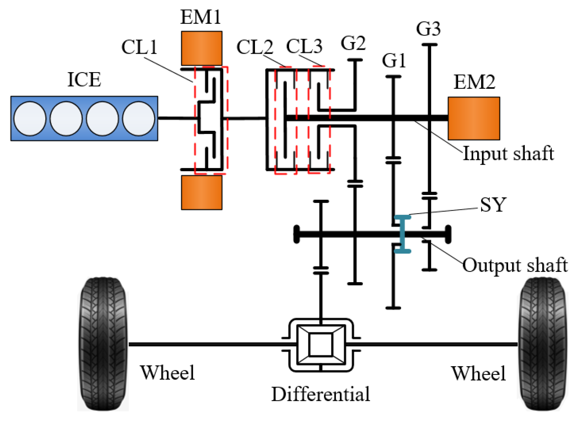
2. Configuration and Working Principles of Novel HEV

This study considered a novel HEV as the research object. A schematic of its configuration is shown in Figure 1, and the main parameters of the vehicle are listed in Table 1. The power sources of the novel HEV included an internal combustion engine (ICE), electric motor 1 (EM1), and electric motor 2 (EM2). A gearbox with three gear pairs was used as the power coupling and power transfer device. Three wet clutches, namely clutch 1 (CL1), clutch 2 (CL2), and clutch 3 (CL3), and a synchronizer (SY) were used as the executive parts for speed ratio switching (mode switching). None of the three wet clutches had the function of driving the vehicle to start by sliding. This study focused on the control of motor and shift actuator (wet clutch) in the powertrain system. Meanwhile, the dynamic coordinated control strategy, for various mechanisms during the shift process, was equally concerned.
An analysis of the structure and working principle of the novel HEV shows that, in the steady-state mode, each power source in the power system had two working states of running and stopping, and each shift actuator (wet clutch and synchronizer) in the transmission system had two working states of engagement and disengagement. Cooperation between the power source and shift actuator caused the gearbox system of the novel HEV to have nine working modes of combined gears, as listed in Table 2, where ID represents the engaged gear(s), regardless of the power flow. It is worth noting that, for the novel hybrid power system proposed in this manuscript, the shift execution components that affect the power transmission path of the gear include the CL2, the CL3, and the synchronizer. The CL1 only determines whether the vehicle works in a pure electric working mode or a hybrid working mode. Therefore, from the perspective of gear analysis, the working state of the CL1 doesn’t need to be taken into consideration.
From the perspective of the control of the powertrain system for an HEV, in order to improve the smoothness, comfort, and power performance of the shift process, it is necessary to focus on solving the control problem of motor active rotary velocity regulation to assist in the clutch engagement and the problem of dynamically coordinating the control of multiple mechanisms in the powertrain system. Therefore, this study considered the 01–11 shift process as a typical shift scheme.

3. Modeling of Powertrain System

This manuscript focuses on the shift control strategy under pure electric working mode. Therefore, this part mainly introduces the modeling principle of motor, wet clutch, and other key components.

3.1. Motor Model

When the vehicle operates in the driving mode, the motor works in the electric motor mode and outputs the torque to drive the vehicle; when the vehicle operates in the braking mode, the motor works in the generator mode and recovers energy under the braking condition. Therefore, the working characteristics of the motor directly affect the dynamic performance and energy recovery performance of a vehicle [30]. After processing the experimental data of the motor working characteristics, the motor efficiency map of EM1 and EM2 were obtained, as shown in Figure 2, and a map of the power loss characteristics of the two motors is shown in Figure 3.

3.1.1. Motor Dynamic Torque

When the motor torque command changes, the output torque of the motor exhibits a certain response lag. The response characteristics of the motor dynamic torque can be expressed by a first-order inertia link:
{ T = 1 1 + τ s T cmd T min T cmd T max ,
where τ is the time constant of the first-order inertia, s indicates the Laplace variable, T is the dynamic mechanical torque on the output shaft of the motor, T cmd represents the motor torque command, T min is the minimum motor torque, and T max is the maximum motor torque.

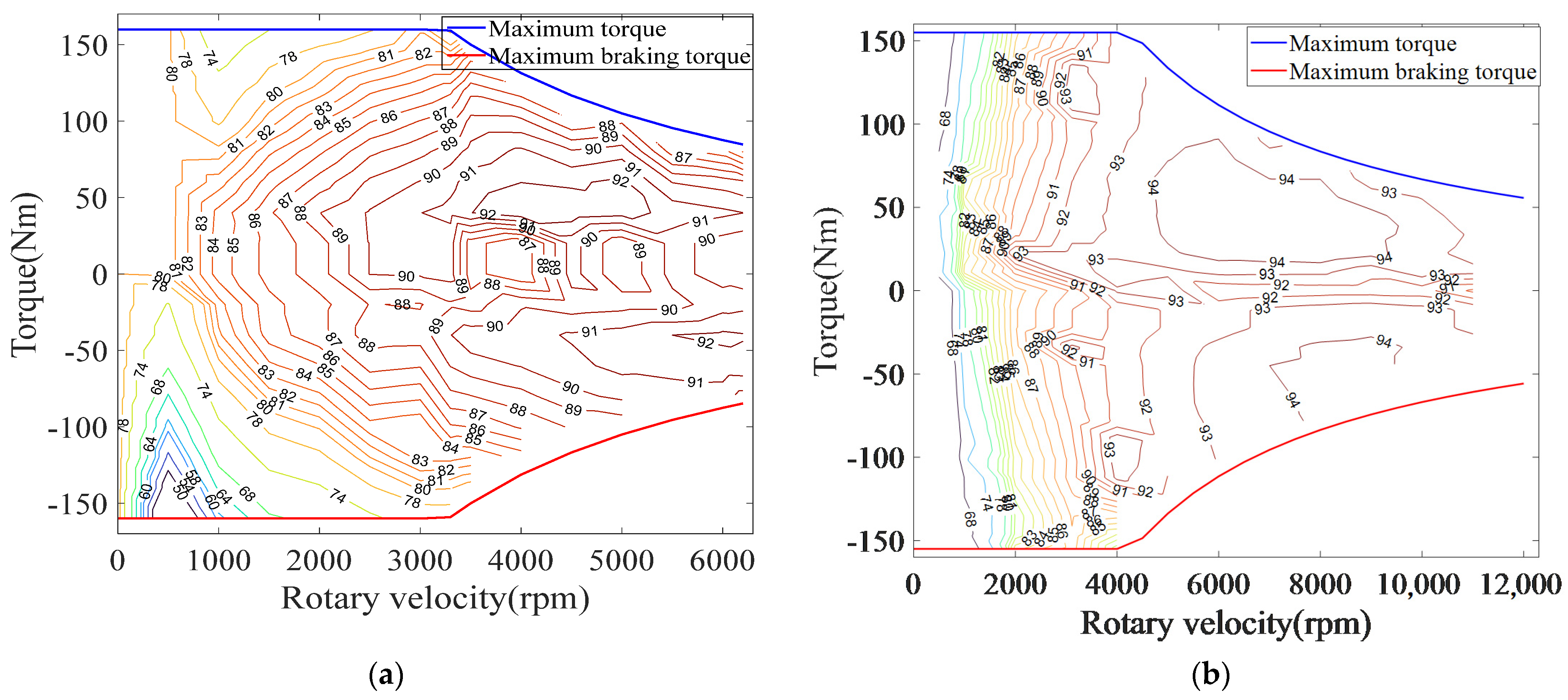
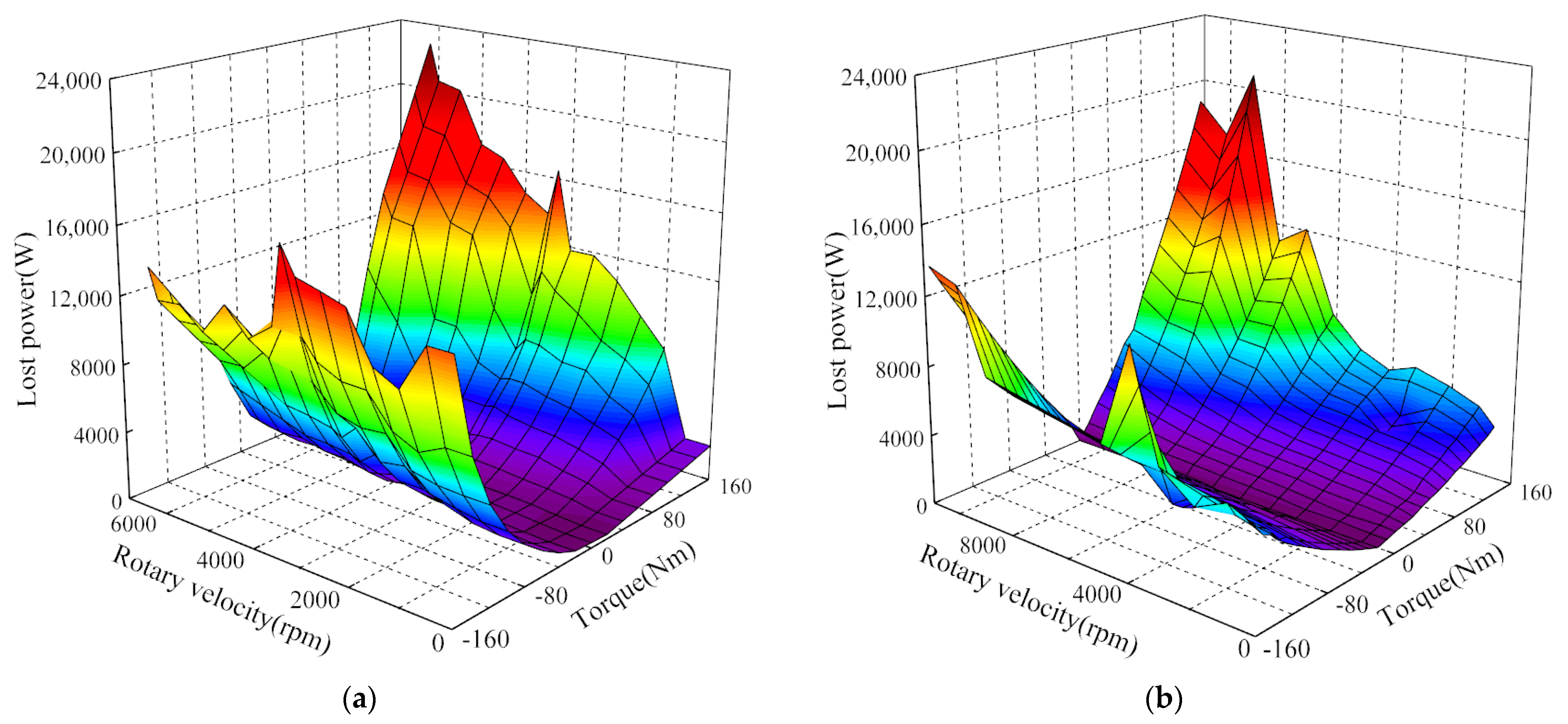
3.1.2. Motor Efficiency

When T > 0 and I > 0 , the motor is in the driving mode, and when T < 0 and I < 0 , the motor is in the braking mode. The motor efficiency is divided into the driving and braking modes:
η = { P mec P elec = P mec P mec + P loss T > 0 P elec P mec = P mec P loss P mec T < 0 ,
where η is the motor efficiency; P elec is the electrical power consumed by the motor; P m e c is the mechanical power output of the motor; P loss is the power loss of the motor.

3.2. Wet Clutch Model

The clutch in the configuration, investigated in this study, was a wet clutch. The control element of a wet clutch is a proportional solenoid valve, and the actuator is a hydraulic cylinder. The main parameters of the wet clutch are listed in Table 3.
When the coil winding of a proportional electromagnet is electrified, the electromagnetic force increases with the current. By changing the current of the input solenoid valve, the size of the opening of the oil outlet can be controlled to change the flow of the hydraulic oil into the clutch hydraulic cylinder, which allows the force on the piston of the hydraulic cylinder to be effectively controlled. Therefore, a hydraulic cylinder is an important part of a wet clutch hydraulic actuator [31]. The main parameters of the clutch hydraulic cylinder used in this study are listed in Table 4.
The balance equation of the proportional solenoid valve spool motion is as follows:
m v x ¨ v + c d x ˙ v + k v ( x v + x 0 ) = F m a g F f l o w ,
where m v and x v represent the spool mass and spool displacement, respectively; c d and k v represent the viscous damping coefficient and spring stiffness of the spool, respectively; x 0 is the compression length of the spring at the initial position of the spool; F m a g is the electromagnetic force; F f l o w is the resultant force of the oil acting on the spool.
The force acting on the piston of the clutch hydraulic cylinder is found as follows:
F p = π ( R 2 2 R 1 2 ) P c F c F s F f ,
where R 2 and R 1 are the piston radius and piston rod radius, respectively; P c is the pressure in the hydraulic cylinder; F c is the centrifugal force of the hydraulic oil acting on the piston; F s is the return spring force; F f is the friction between the piston and cylinder wall.
The hydraulic cylinder is a direct component that controls the pressure of the clutch. The clutch active plate and the piston of the hydraulic cylinder are rigidly connected together and move with the movement of the piston of the hydraulic cylinder, and its movement displacement is equal to the displacement of the piston. The dynamic flow continuity equation of the working cylinder is as follows:
Q = A d y d t + C t c P L + V t β e d P L d t
where Q is the actual flow of hydraulic pump; A is the working area of hydraulic cylinder; y represents the displacement of the working piston; C t c is the total leakage coefficient; P L represents load pressure; V t represents the volume of the chamber from the outlet of the slide valve to the piston of the hydraulic cylinder; β e is the effective bulk elastic modulus of oil.
After Laplace transform of Formula (5), the following formula can be obtained:
Q = A s Y ( s ) + C t c P t + V t β   c P L ( s ) s
The general expression of the spool valve load flow is:
Δ Q = K q Δ x K c Δ P L
where K q is the flow gain; K c is the flow pressure coefficient.
K q = Q x
K c = Q P L
It can be obtained after Laplace transform of Formula (7),
Q = K q x K c P L
Equations (6) and (10) can be combined to obtain the Lagrangian variable equation of the working piston displacement:
Y ( s ) = K q A s X ( s ) K c + C t c + V t β e s A s P L ( s )
According to Newton’s second law and the dynamic relationship of the hydraulic cylinder piston, the dynamic differential equation of the hydraulic cylinder piston is established as follows:
m p d 2 y d t 2 + C p d y d t + K P y = F p
where m p is the sum of the masses of the piston and the clutch active plate; C p represents the viscous friction coefficient between the clutch cylinder and the piston; K p represents the stiffness coefficient of piston return spring; F p is the force of the fluid acting on the piston.
The force of fluid acting on the piston is composed of static pressure and dynamic pressure.
F P = F S + F ω = P L A + π ρ ω c d 2 4 ( R 2 2 R 1 2 ) 2
where F s and F ω represent the static pressure and dynamic pressure of the fluid acting on the piston respectively; ω c d is the speed at the input end of the clutch.
The control variable of wet multi disc clutch simulation model is clutch oil pressure, and the output variable is its transmitted torque. The torque transmission characteristics during the combination process are:
Clearance elimination phase:
T c = 0
Sliding stage:
T c = s i g n ( n m n e ) · μ · Z · S ( P P 0 ) · R c
Locking phase:
T c = T e m
In Equations (14)–(16), T c and T e m are the torque transmitted by the clutch and the torque of the motor, respectively; n m and n e are the rotary velocity of the active end and the driven end of the clutch respectively; μ is the dynamic friction coefficient of the clutch; Z is the number of friction surfaces of the clutch; S is the acting area of clutch piston; P and P 0 are clutch engagement oil pressure and initial oil pressure, respectively; R c is the equivalent friction radius of the clutch.

3.3. Vehicle Longitudinal Dynamics Model

The vehicle longitudinal dynamics model calculates the wheel speed and rotational acceleration, based on the semi-shaft drive torque and wheel resistance torque, and feeds them back to the driver and the vehicle controller.
J v e h   ω ˙ w h e e l   = T a x l e   ( F a e r o   + F s l o p e   + F f r i c   ) R w h e e l ,
where J v e h is the moment of inertia of the vehicle equivalent to the wheels; R w h e e l is the tire radius; F a e r o   , F s l o p e   , and F f r i c   represent air resistance, ramp resistance, and friction resistance, respectively
F a e r o   = C d A 21.15 v 2 ,
where v is the vehicle speed;   C d and A represent drag coefficient and windward area, respectively
F s l o p e   = M g sin α ,
where M is the mass of the whole vehicle and α is the slope
F f r i c = M g f   ( v 0 ) ,
where f is the rolling friction coefficient.

3.4. Model Validation

In this manuscript, the motor model, power battery model, vehicle dynamics model, clutch model, hydraulic cylinder model, solenoid valve model, and driver model are established in AMESim. In order to verify the accuracy of the whole vehicle power transmission model, the simulation verification is carried out based on the new European driving cycle (NEDC). The simulation results are shown in Figure 4. It can be seen, from Figure 4, that the simulated vehicle speed can well follow the target vehicle speed under NEDC working condition, and the speed error between them is very small. Therefore, the established vehicle model lays a foundation for the study of gear switching control strategy.

4. Method Analysis and Control Strategy Development

In this study, the 01–11 gear shifting scheme was studied as a typical shift condition. The control flow chart of gears 01–11 is shown in Figure 5. When the vehicle operated in the initial gear (gear 01), EM1 was in the stopping state, and EM2 transmitted power to the output shaft of the gearbox through the G1 gear pair. When the shift schedule was triggered, the synchronizer remained engaged with the G1 gear pair; the rotary velocity of the active end of CL2 was calculated; EM1 was started; the rotary velocity was regulated with the rotary velocity of the active end of CL2 as the target rotary velocity (definition: the clutch friction plate near the EM1 side was the driven end of the clutch, and the clutch friction plate near the gearbox input shaft side was the active end of the clutch). While regulating the rotary velocity of EM1, the initial engagement oil pressure of CL2 was controlled. When the rotary velocities of the active and driven ends of CL2 were basically the same and the initial engagement oil pressure of CL2 was established, CL2 began to be engaged. After CL2 was fully engaged, the output torques of EM2 and EM1 were coordinated to ensure that the total torque of the gearbox output shaft remained stable. After shifting, EM1 and EM2 drove the vehicle together. The power of the motors was transmitted to the output shaft of the gearbox through the G1 gear pair, and the vehicle ran in the new gear (gear 11). This shift process included two important problems: the motor rotary velocity control (Section 4.1) and coordinated control of the motor rotary velocity and clutch initial engagement oil pressure (Section 4.2).

4.1. Motor Rotary Velocity Regulation Control Algorithm

To improve the shifting time and reduce the friction loss of the clutch, it was necessary to actively control the motor rotary velocity to assist in the clutch engagement. For the control algorithm, adopted by the motor rotary velocity regulation control technology, PID regulator is a relatively common adjustment method used in the industry. However, with the progress of technical research, various advanced intelligent control algorithms are gradually applied to the motor rotary velocity regulation control technology, such as the motor rotary velocity regulation control strategy integrating a variety of control methods. Table 5 compares the common motor rotary velocity regulation control algorithms with the control algorithms proposed in this paper.

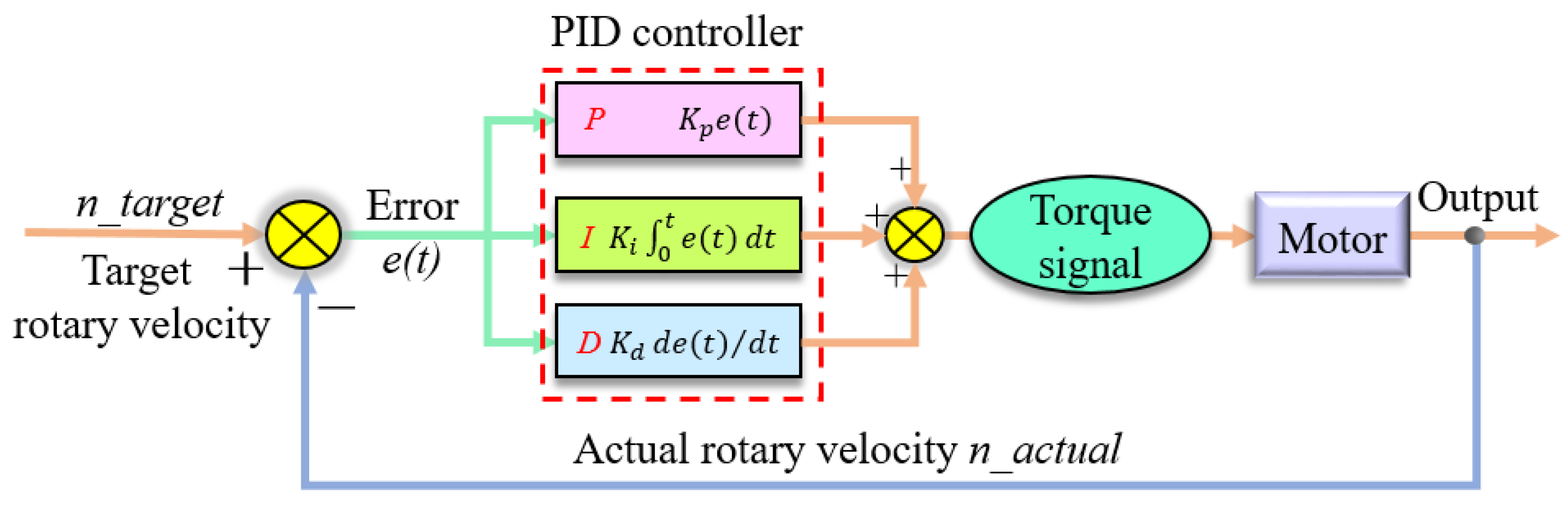
4.1.1. PID Algorithm

The PID control algorithm has the characteristics of a simple structure and the ability to achieve effective control even when no mathematical model of the research object is available. It has become a common control algorithm for motor rotary velocity regulation. The control principle diagram of a motor rotary velocity control system, based on a PID algorithm, is shown in Figure 6. The input of the PID controller is the difference between the target rotary velocity and the actual rotary velocity of the motor, and the output is the torque command signal for the motor. The PID controller is mainly controlled by adjusting the three control parameters, which are the proportional, integral, and differential coefficients, to achieve the following target values. The goal of the PID controller in this study was to make the actual rotary velocity of the motor ( n _ a c t u a l ) follow the target rotary velocity ( n _ t a r g e t ).
The output of the PID controller was the command, u ( k ) , sent to the controlled object:
u ( k ) = K p e ( k ) + K i 0 t e ( t ) d t + K d d e ( t ) d t ,
where e ( k ) is the error between the target rotary velocity and the actual rotary velocity; K p is the proportional gain coefficient; K i is the integral gain coefficient; K d is the differential gain coefficient.

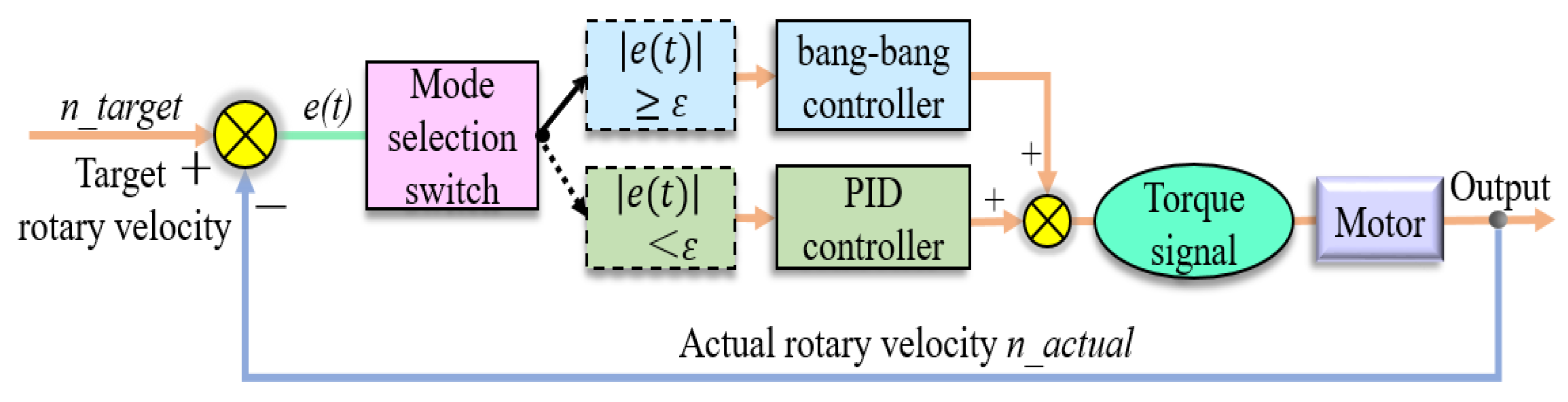
4.1.2. PID–Bang-Bang Compound Algorithm

The bang-bang control algorithm is also known as the minimum-time control algorithm. Its primary control principle is to make the system switch from one state to another at the fastest speed in the control domain. Considering the purpose of rapidly following the target rotary velocity, the bang-bang control algorithm is a control algorithm that can be considered. In this study, the PID control algorithm and bang-bang control algorithm were coupled to form a PID–bang-bang compound control algorithm, and a schematic of the principle is shown in Figure 7. Here, ε is the difference between the target rotary velocity and the actual rotary velocity corresponding to the mode switching point, that is, the algorithm switching threshold of the bang-bang control mode and the PID control mode.
The PID–bang-bang compound controller was used to control the rotary velocity of the motor in the shifting process, where the control mode was selected online using a mode selection switch. When the difference between the target rotary velocity and the actual rotary velocity was large, the bang-bang control algorithm was used to ensure that the motor rotary velocity reached the target rotary velocity as soon as possible. When the difference was small, the PID control algorithm was used to improve the robustness and control accuracy of the control system. The influence of the switching timing of the two algorithms on the motor rotary velocity regulation effect will be further explained in Section 5.1.3.

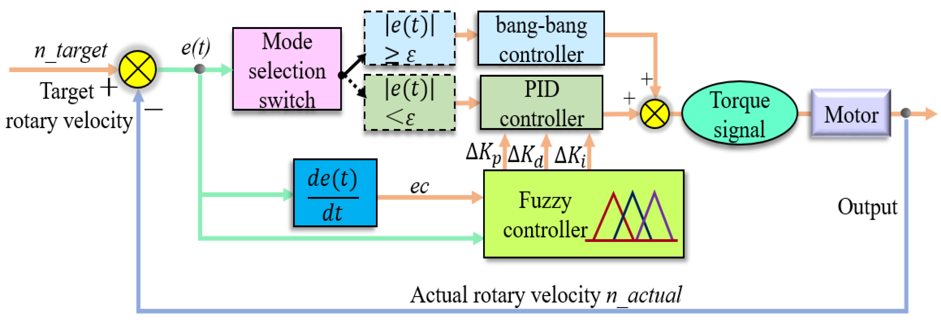
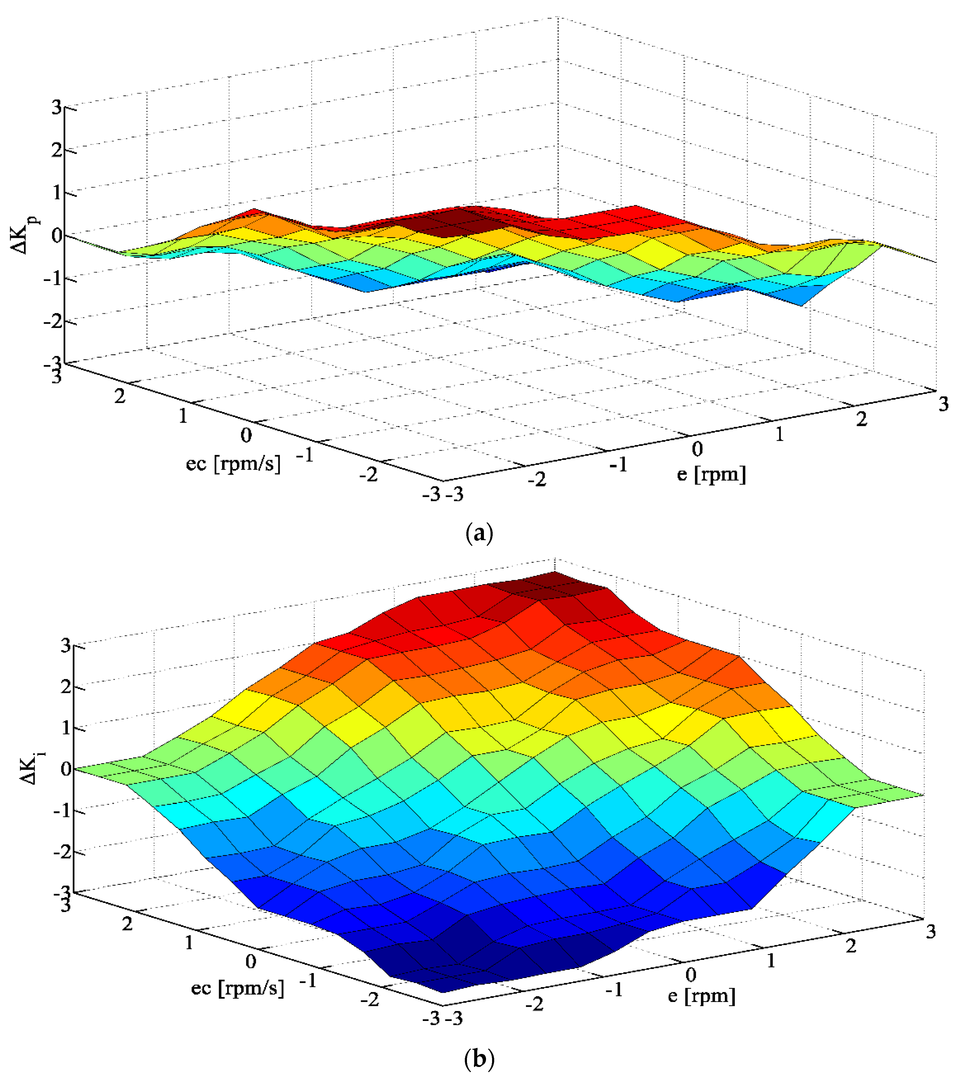
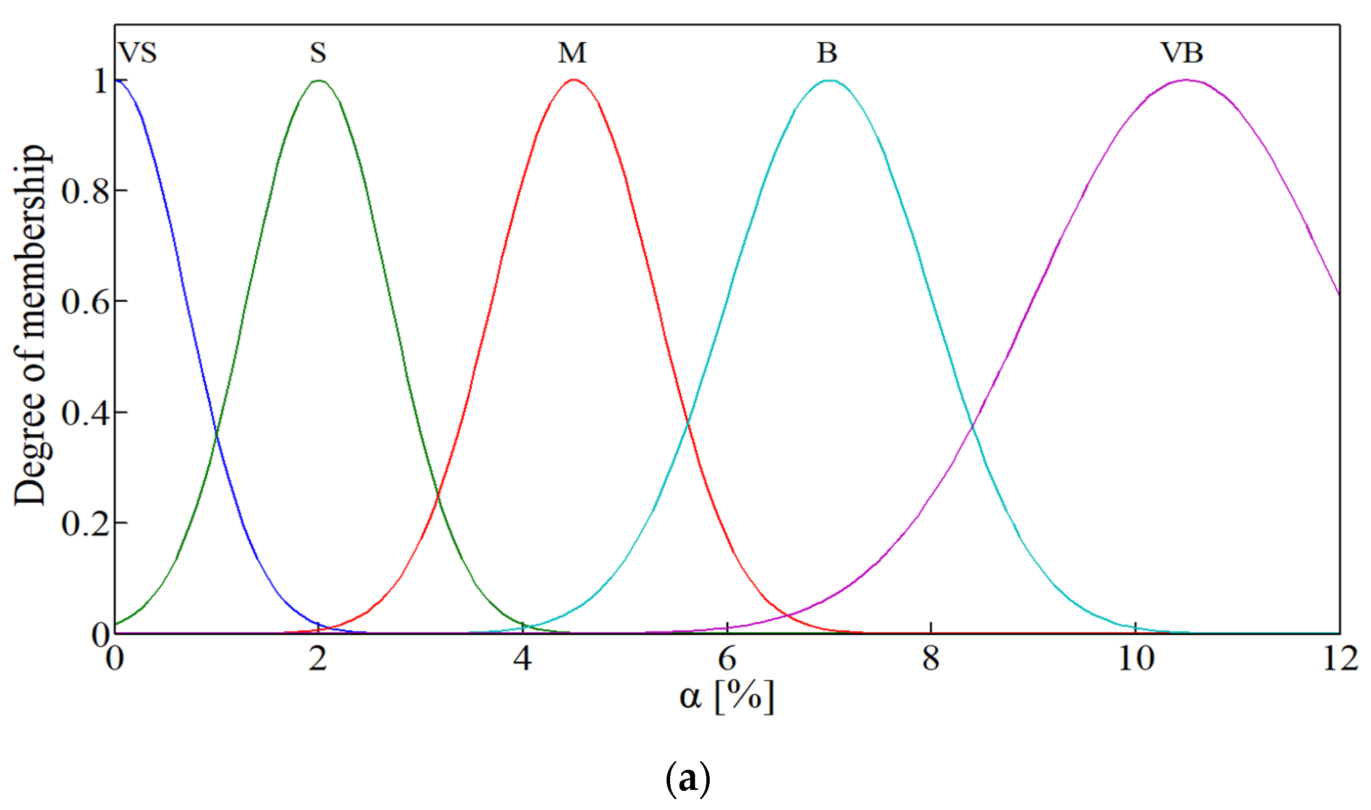
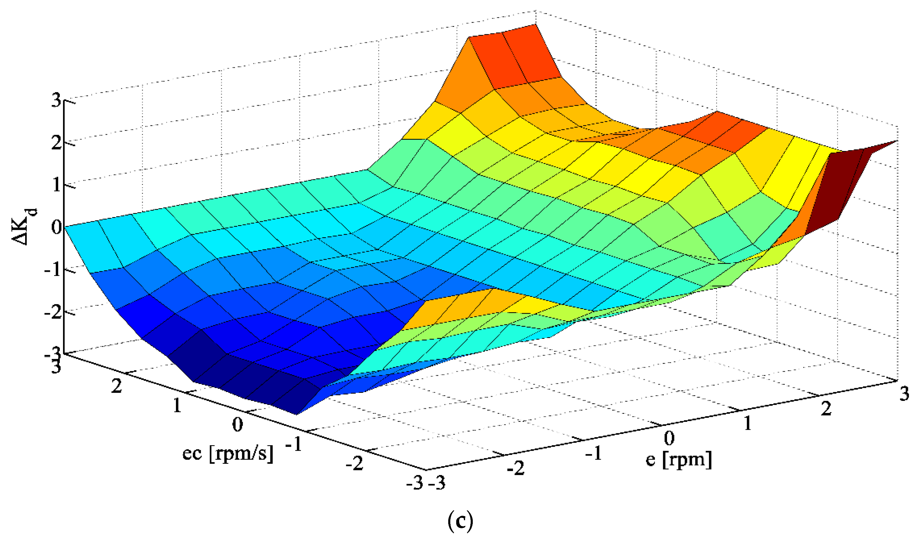
4.1.3. PID–Bang-Bang–Fuzzy Compound Intelligent Algorithm

Fuzzy control is an intelligent control algorithm that is suitable for objects that cannot be accurately modeled and nonlinear complex systems. It is a control algorithm with broad application prospects. This study further investigated combining the advantages of the fuzzy control algorithm with the PID–bang-bang compound control algorithm to form a PID–bang-bang–fuzzy compound intelligent algorithm. A schematic of the control principle of the motor rotary velocity control system, based on the PID–bang-bang–fuzzy compound intelligent algorithm, is shown in Figure 8. When the error between the real-time value and the target value was greater than threshold value ε, to quickly eliminate the large error and improve the convergence speed, the system applied the bang-bang controller. When the error was less than threshold value ε, to ensure the control accuracy of the system in the steady state, the PID controller was used, with the fuzzy algorithm used to calculate the PID parameters. In this way, the online self-tuning of the PID controller parameters could be realized, and the performance of the PID controller could be further improved to better adapt to changes in the motor rotary velocity control system parameters and working conditions.
The fuzzy controller is the core part of the fuzzy control system, with its design based on experience and effective fuzzy control rules. In the PID–bang-bang–fuzzy compound intelligent algorithm, the fuzzy controller was mainly used to adjust Kp, Ki, and Kd. The input of the fuzzy controller was the error of the rotary velocity (e) and the change rate of the error of the rotary velocity (ec). The output was the variation of the proportional coefficient (ΔKp), integral coefficient (ΔKi), and differential coefficient (ΔKd). The following fuzzy subsets of e, ec, ΔKp, ΔKi, and ΔKd were selected: {NB, NM, NS, ZO, PS, PM, PB}, which represented negative big, negative middle, negative small, zero, positive small, positive middle, and positive big, respectively.
The triangle membership function is simple and convenient. At the same time, it does not occupy too much memory in the calculation process. In this design, the membership function types of inputs e and ec, as well as outputs ΔKp, ΔKi, and ΔKd were all triangles. The domains of the inputs and outputs were (−3.3). The membership functions are shown in Figure 9. In order to improve the adjustment speed of fuzzy PID, triangular membership function is used. The fuzzy rule surfaces of the output variables are shown in Figure 10.

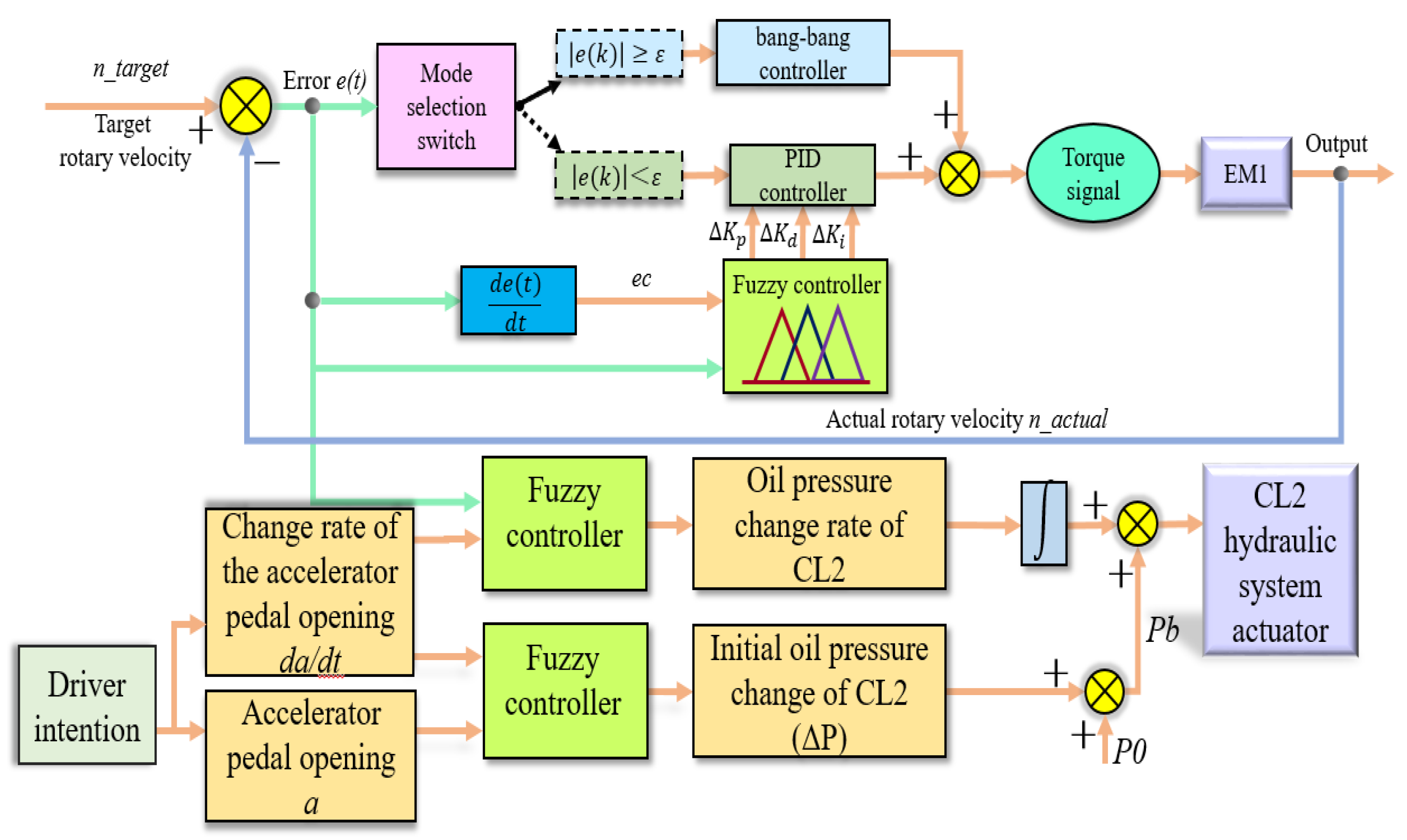
4.2. Coordinated Control Strategy for Motor and Clutch

For a configuration where one end of the wet clutch is directly connected to the motor, to solve the problems of the long time needed to synchronize the rotary velocity and the large sliding friction work, which affect the shift quality during the process of engaging the clutch, this paper proposes a dynamic coordinated control strategy that combines active rotary velocity synchronization at both ends of the clutch and the establishment of the initial engagement oil pressure of the clutch. A schematic of this control strategy is shown in Figure 11. For the EM1 rotary velocity regulation control, in the case of a known target rotary velocity (n_target), applying a compound intelligent algorithm for the EM1 rotary velocity closed-loop control system can assist the rotary velocities of both ends of CL2 to quickly, and smoothly, approach the target. On the other hand, the control of CL2 can be attributed to the control of the oil pressure of CL2. Furthermore, the initial engagement pressure of CL2 is determined by the driver’s operation intention, where the accelerator pedal opening (a) and change rate of the accelerator pedal opening (da/dt) represent the driver’s intention. The overall control objective of the dynamic coordinated control strategy is to ensure that the engagement process of CL2 meets both the time and slipping friction work requirements.
A fuzzy controller was designed to establish the initial engagement oil pressure of CL2, which used the driver’s accelerator pedal opening (a) and the change rate of the accelerator pedal opening (da/dt) as inputs and the initial oil pressure change (ΔP) as the output. The initial engagement pressure (Pb) of CL2 could be obtained by summating ΔP with the preset initial oil pressure (P0). In this fuzzy controller, the ranges of a and da/dt were (0,12), and the fuzzy subsets were divided into five levels {VS, S, M, B, VB}, which represented very small, small, medium, big, and very big, respectively. The Gaussian function with good stability was used as a membership function for the two input variables. Among them, the fuzzy subsets of a corresponded to the different requirements of the driver for the driving force, and its membership functions are shown in Figure 12a. The fuzzy subsets of da/dt corresponded to the different requirements of the driver for the acceleration response, and their membership functions are shown in Figure 12b. The range of the initial pressure change (ΔP) of CL2 was (0,12), and the fuzzy subset was divided into seven levels {VS, S, MS, M, MB, B, VB}, which represented very small, small, medium small, medium, medium big, big, and very big, respectively. These corresponded to the initial engagement pressure change of CL2. The triangle function was used as a membership function, as shown in Figure 12c.
According to the established fuzzy rules, the Mandani method was used for fuzzy reasoning. To obtain the specific output value, the centroid method was used to solve the center of the area surrounded by the membership curve and horizontal coordinates. Finally, the fuzzy controller input-output rule surface of CL2, in the initial oil pressure rising stage, was formed, as shown in Figure 13.

5. Simulation Results and Analysis

This study used a co-simulation platform, composed of the powertrain model built in AMESim and the control strategy model built in MATLAB, to simulate and analyze the laws of the control algorithm in relation to the motor rotary velocity regulation performance, and the process of shifting gears from 01–11. The schematic diagram of the co-simulation platform is shown in Figure 14.

5.1. Motor Rotary Velocity Regulation Performance Analysis

5.1.1. Based on PID Algorithm

When the controlled object is known, there are three methods of PID parameter tuning: Ziegler–Nichols method, ISTE optimal setting method, and experience based method. This manuscript adopts the empirical method to adjust the PID control parameters. For example, when the target rotary velocity is 3000 rpm, Kp = 16, Ki = 1, Kd = 0.2. Figure 15 shows the changes in the motor rotary velocity with the different target rotary velocities when the PID algorithm was applied to the motor rotary velocity control system. As can be seen from Figure 15, the rise time, peak time, and regulation time were long in the process of rotary velocity regulation. Thus, the dynamic response effect was poor. The specific law was that, with an increase in the target rotary velocity, the rise time and peak time of the motor rotary velocity regulation remained basically unchanged, while the regulation time and maximum overshoot both gradually increased with an approximately linear growth trend.

5.1.2. Based on PID–Bang-Bang Compound Algorithm

Figure 16 presents the law for the motor rotary velocity change with different target rotary velocities when the PID–bang-bang compound algorithm was applied to the motor rotary velocity control system. Overall, the rise time and peak time of the rotary velocity regulation process were short, but the regulation time was long, and the motor rotary velocity fluctuated significantly. The specific law was that, by increasing the target rotary velocity, the rise time, peak time, and regulation time of the motor rotary velocity regulation gradually increased with an approximately linear growth trend. Meanwhile, the maximum overshoot gradually increased with a nonlinear increasing trend: when the target rotary velocity was lower than 2000 rpm, the increasing trend was large; when the target rotary velocity was higher than 2000 rpm, the change tended to be gentle.

5.1.3. Based on PID–Bang-Bang–Fuzzy Compound Intelligent Algorithm

When the PID–bang-bang–fuzzy compound intelligent algorithm was applied to the motor rotary velocity control system, the law of the motor rotary velocity changed with the different target rotary velocities shown in Figure 17. As shown in Figure 17, given a certain target rotary velocity, the control system based on the PID–bang-bang–fuzzy compound intelligent algorithm could ensure that the actual rotary velocity of the motor followed the target rotary velocity. In general, the rise time, peak time, and regulation time of the rotary velocity regulation process were short; the motor rotary velocity fluctuation was small; the dynamic response effect was significantly improved. The specific law was that, with an increase in the target rotary velocity, the rise time, peak time, and regulation time of the motor rotary velocity regulation gradually increased and showed an approximately linear growth trend. However, the maximum overshoot gradually decreased, and its decreasing trend presented a nonlinear law. When the target rotary velocity was lower than 2000 rpm, the decreasing trend was large; whereas, when the target rotary velocity was higher than 2000 rpm, the change tended to be gentle.
Figure 18 shows that, when the motor rotary velocity control system applied the PID–bang-bang–fuzzy compound intelligent algorithm, and the target rotary velocity was 3000 rpm, the law of the motor rotary velocity changed with the different algorithm thresholds. Evidently, different algorithm thresholds had different effects on the rotary velocity regulation effect. The specific law was that, with an increase in the algorithm threshold, the rise time of the motor rotary velocity regulation remained unchanged. However, the peak time, regulation time, and maximum overshoot gradually decreased, and the decreasing trend was nonlinear; when the algorithm threshold was lower than 300 rpm, the decreasing amplitude was large, and when the algorithm threshold was higher than 300 rpm, the change tended to be gentle.

5.1.4. Comparison of Different Control Algorithms

When setting the target rotary velocity as constant (3000 rpm), the rotary velocity regulation effects of the different control algorithms (PID, PID–bang-bang, and PID–bang-bang–fuzzy) are shown in Figure 19. The different control algorithms had different effects on the rotary velocity regulation effect. The rise time and peak time of the PID–bang-bang compound algorithm and PID–bang-bang–fuzzy compound intelligent algorithms were basically the same, and they were significantly smaller than those of the PID algorithm. Furthermore, the maximum overshoot values of the PID–bang-bang compound algorithm and PID–bang-bang–fuzzy compound intelligent algorithm were higher than that of the PID algorithm, but the difference was small. In addition, the regulation time of the PID algorithm was the longest, and that of the PID–bang-bang–fuzzy compound intelligent algorithm was the shortest. After the regulation time, the rotary velocity regulation results of the PID algorithm and PID–bang-bang compound algorithm still exhibited small fluctuations, whereas the rotary velocity under the PID–bang-bang–fuzzy compound intelligent algorithm was steady. The high-frequency residual oscillation in Figure 19 (right) is mainly caused by the control overflow problem of high-frequency dynamics. In general, the steady-state response and dynamic response of the motor rotary velocity regulation process were significantly improved when the PID–bang-bang–fuzzy compound intelligent control algorithm was applied.

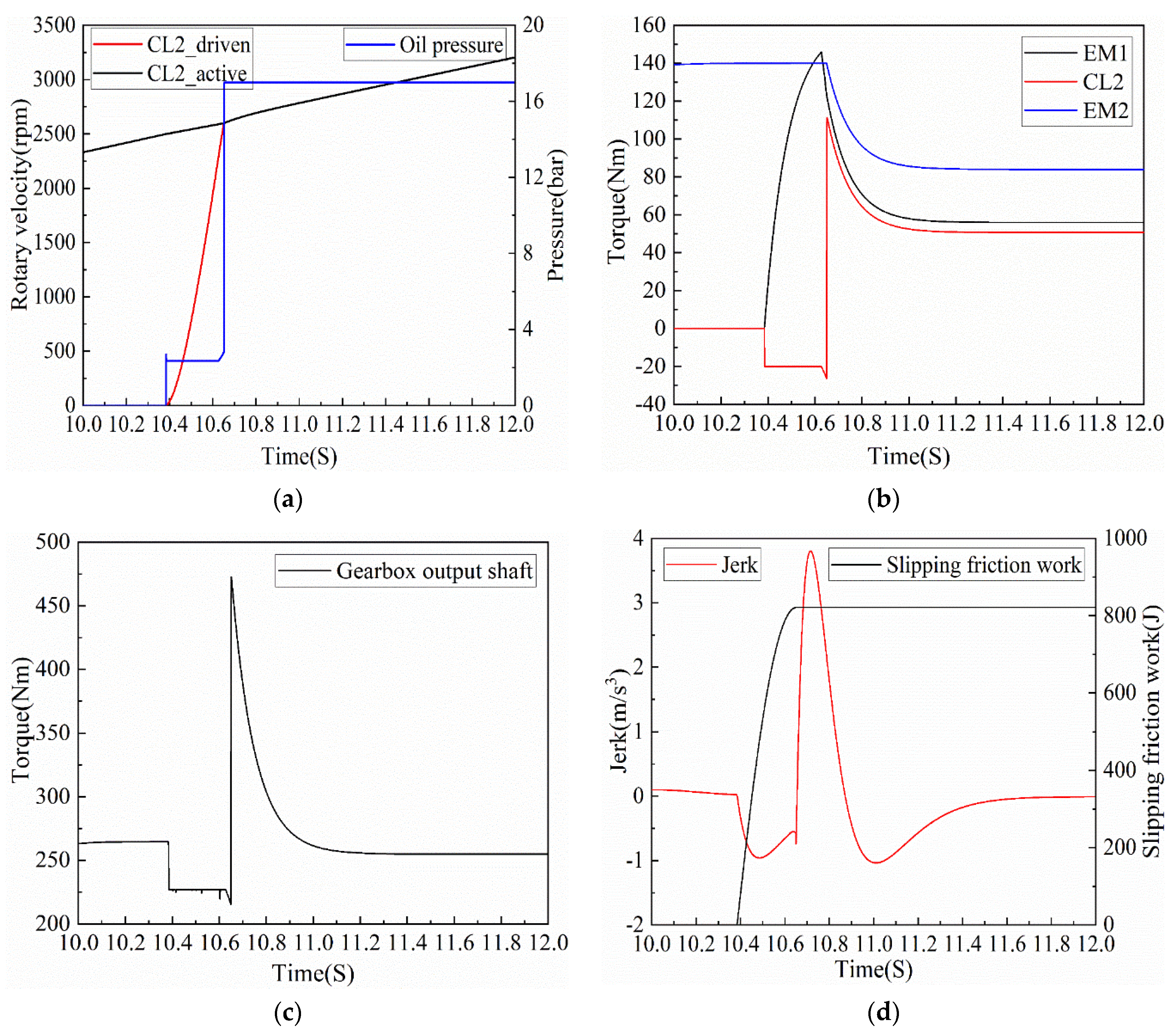
5.2. Gear Shift Performance Analysis

The simulation conditions used in this study are shown in Figure 20. In the shift process of 01–11, the sign of the shift start was that the driven end of CL2 began to generate rotary velocity (when the rotary velocity was not zero). According to the rotary velocity curves of the active and driven ends of CL2, given in Figure 21, the starting time of shifting was 10.38 s. To better analyze the dynamic change law of each variable in the shift process, an interval of 10–12 s was selected for display and analysis.
Figure 22 shows the shift simulation results, from 01–11, when the gear shift coordinated control strategy, based on the common PID control algorithm, was used to regulate the motor rotary velocity. It can be seen in Figure 22a that the time from the generation of rotary velocity at the driven end of CL2 to the complete equality of the rotary velocities at the active and driven ends of CL2 was 0.42 s (10.38 s to 10.80 s). At the same time, the initial oil pressure of CL2 was established during the process of EM1, regulating the rotary velocity of the driven end of CL2. As shown in Figure 22b, before shifting (before 10.38 s), EM2 independently output torque to drive the vehicle. At 10.38 s, EM1 started and output torque. The torque presented a trend of first increasing and then decreasing, and there was a certain degree of fluctuation, which was mainly due to the instability of the PID control algorithm. The dynamic response effect of the PID controller is unstable, mainly because it does not have the ability to adaptively adjust the control parameters. It is worth noting that, in the EM1 rotary velocity regulation stage, CL2 was not engaged. Thus, the torque fluctuation of EM1 would not cause a disturbance in the driving of the vehicle. For CL2, the torque changed to −20 Nm, mainly because CL2 had the initial oil pressure in its empty stroke stage, which led to a certain friction torque. When CL2 reached the sliding friction stage, the friction torque further increased to −40 Nm. After the shift, the torque of EM1 could be transmitted to the input shaft of the gearbox, reducing the torque of EM2. However, the sum of the torques of EM1 and EM2 was basically the same as that of EM2 driven alone before the shift. Figure 22c shows that the output torque of the gearbox was always positive, and there was no power interruption during the shift process. Figure 22d shows that, under the gear shift coordinated control strategy, based on the PID control algorithm, during the whole shift process, the maximum value of jerk was 1.46 m/s3, and the slipping friction work, generated by CL2, was 1017 J.
Figure 23 shows the results when the gear shift coordinated control strategy proposed in this study, based on the PID–bang-bang–fuzzy compound intelligent algorithm, was used to regulate the rotary velocity of EM1, and the shift process from 01 to 11 was simulated. It can be seen, in Figure 23a, that the time from the generation of rotary velocity at the driven end of the CL2 to the complete equality of the rotary velocities at the active and driven ends of CL2 was 0.27 s (10.38 s to 10.65 s). Meanwhile, the initial oil pressure of CL2 was established during the process of EM1, regulating the rotary velocity of the driven end of CL2, which showed that the coordinated control strategy of the EM1 rotary velocity and CL2 oil pressure had a significant control effect. It can be seen, from Figure 23b, that the torque variation law of the power source and CL2 was consistent with Figure 22b. The difference was that the output torque of EM1 steadily increased in the rotary velocity regulation stage, which was mainly due to the stable control effect of the PID–bang-bang–fuzzy intelligent control algorithm. In addition, the torque of EM1 didn’t increase from t=10.4 s to the maximum value as expected, mainly because the motor model established in this paper is a dynamic model that considers the first-order inertia link. Figure 23c shows that the output torque of the gearbox was positive at all times, and there was no power interruption during the shift process. According to Figure 23d, the maximum jerk was 3.77 m/s3, and the slipping friction work, generated by the CL2, was 821.3 J during the entire shift process.
A further comparative analysis of the above two gear shift coordinated control strategies and their simulation results showed that, because EM2 had torque output during the whole shift process of 01–11, there was no shift power interruption phenomenon. In other words, the maximum jerk, obtained based on the above two control strategies, was relatively small. As for the other two evaluation indices of the shift effect (shift time and clutch slipping friction work), it can clearly be seen from Table 6 that, compared with the shift control strategy based on the PID control algorithm, the shift time and clutch slipping friction work of the shift control strategy based on the PID–bang-bang–fuzzy compound intelligent control algorithm proposed in this paper were reduced by 35.7% and 19.2%, respectively. Therefore, the gear shift coordinated control strategy proposed in this paper could significantly reduce the shift time and slipping friction work, and it could effectively improve the shift quality.

6. Conclusions

This study considered a novel HEV with dual motors as the research object. Based on the structural characteristics of the powertrain system, the working modes of the combined gears were proposed for a gear shift. Furthermore, this study investigated the control effects of various motor rotary velocity control algorithms with different target rotary velocities. At the same time, this paper also proposes a dynamic coordinated control strategy to achieve better shift quality. The main conclusions are as follows.
(1)
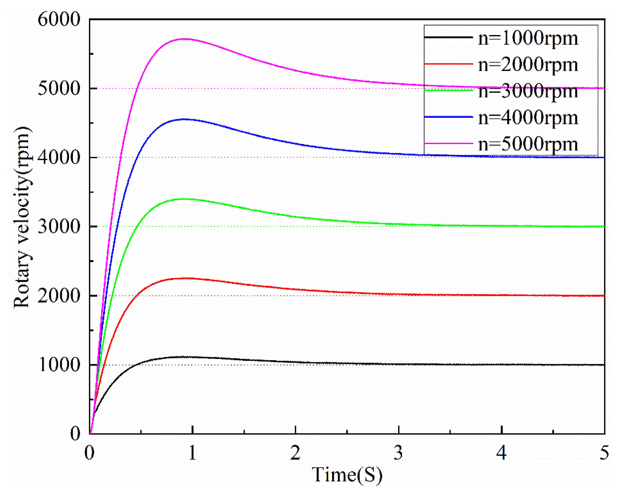
When the PID algorithm was applied to the motor rotary velocity control system, with an increase in the target rotary velocity, the rise time and peak time of the motor rotary velocity regulation were basically unchanged, while the regulation time and maximum overshoot both gradually increased with an approximately linear growth trend.
(2)
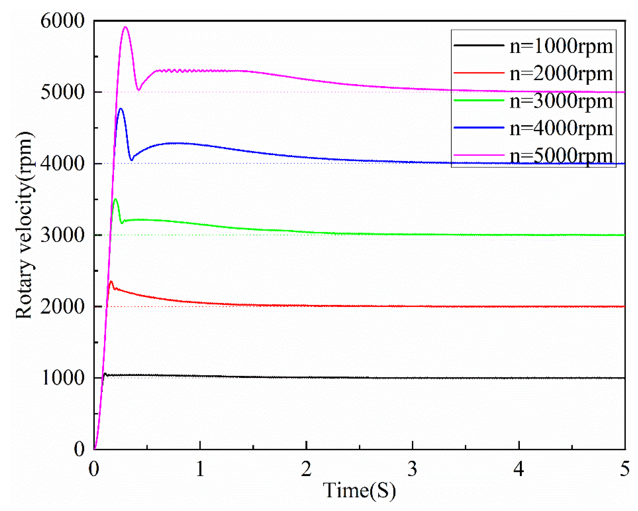
When the PID–bang-bang compound algorithm was applied to the motor rotary velocity control system, as the target rotary velocity was increased, the rise time, peak time, and regulation time of the motor rotary velocity regulation gradually increased with an approximately linear growth trend. Meanwhile, the maximum overshoot also gradually increased with a nonlinear increasing trend.
(3)
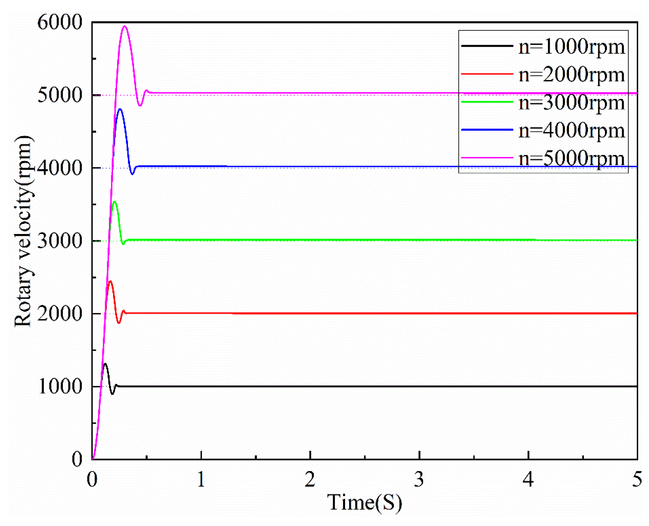
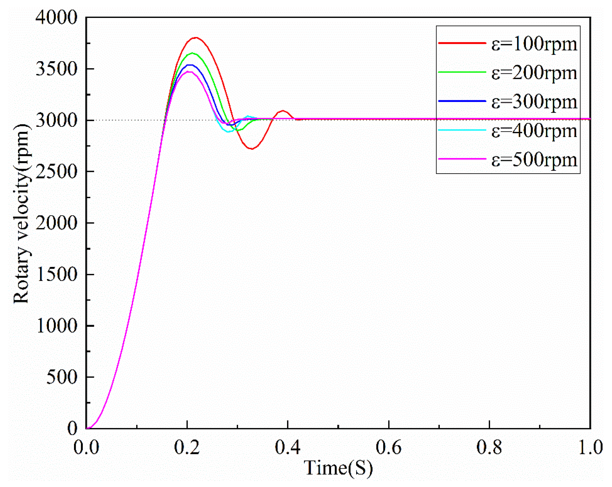
When the PID–bang-bang–fuzzy compound intelligent algorithm was applied to a motor rotary velocity control system, with an increase in the target rotary velocity, the rise time, peak time, and regulation time of the motor rotary velocity regulation gradually increased, and it showed an approximately linear growth trend. However, the maximum overshoot gradually decreased, and its decreasing trend presented a nonlinear law. Furthermore, when the target rotary velocity was a constant value (3000 rpm), with an increase in the algorithm threshold, the rise time of the motor rotary velocity regulation remained unchanged. The peak time, regulation time, and maximum overshoot gradually decreased, and the decreasing trend was nonlinear.
(4)
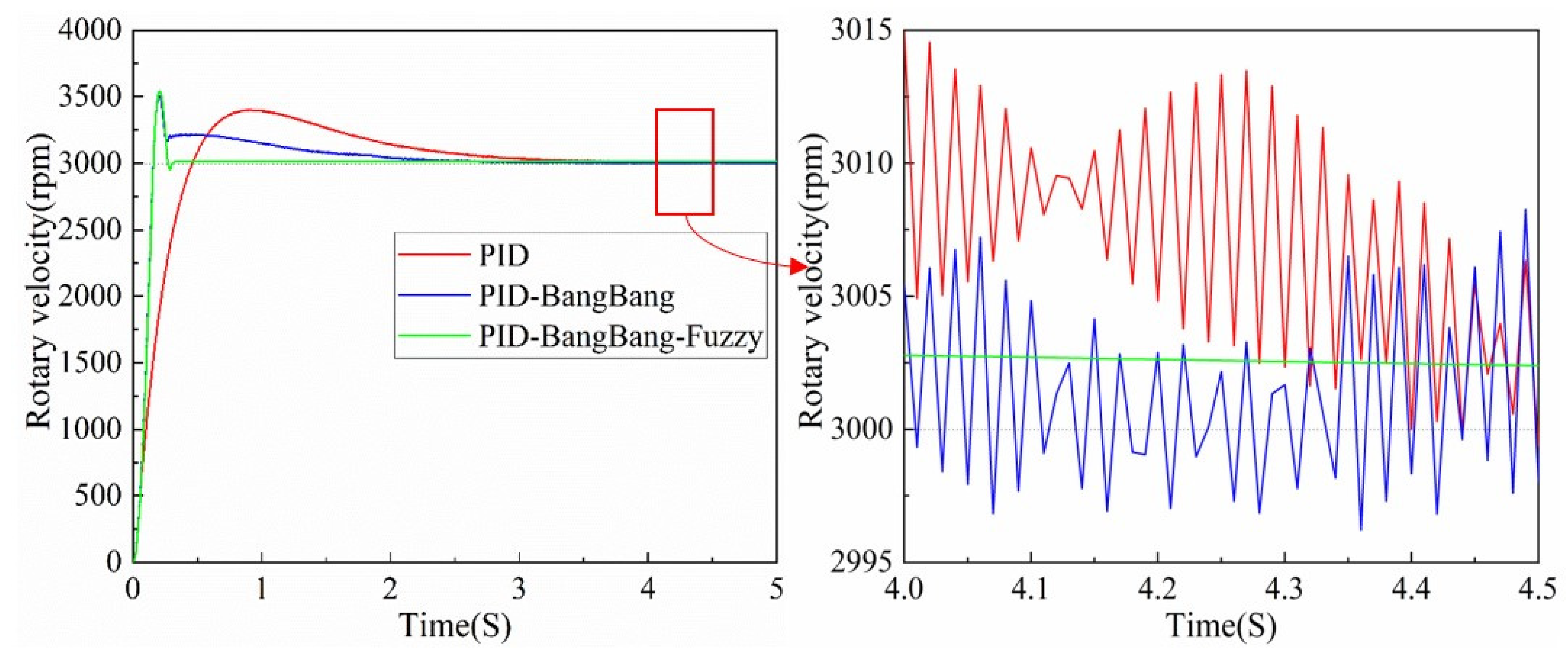
For the motor rotary velocity regulation control algorithm, different control algorithms have different effects on the rotary velocity regulation effect. Compared with PID and PID–bang-bang, the steady-state response and dynamic response of the motor rotary velocity regulation process are significantly improved by using the PID–bang-bang–fuzzy compound intelligent control algorithm proposed in this paper.
(5)
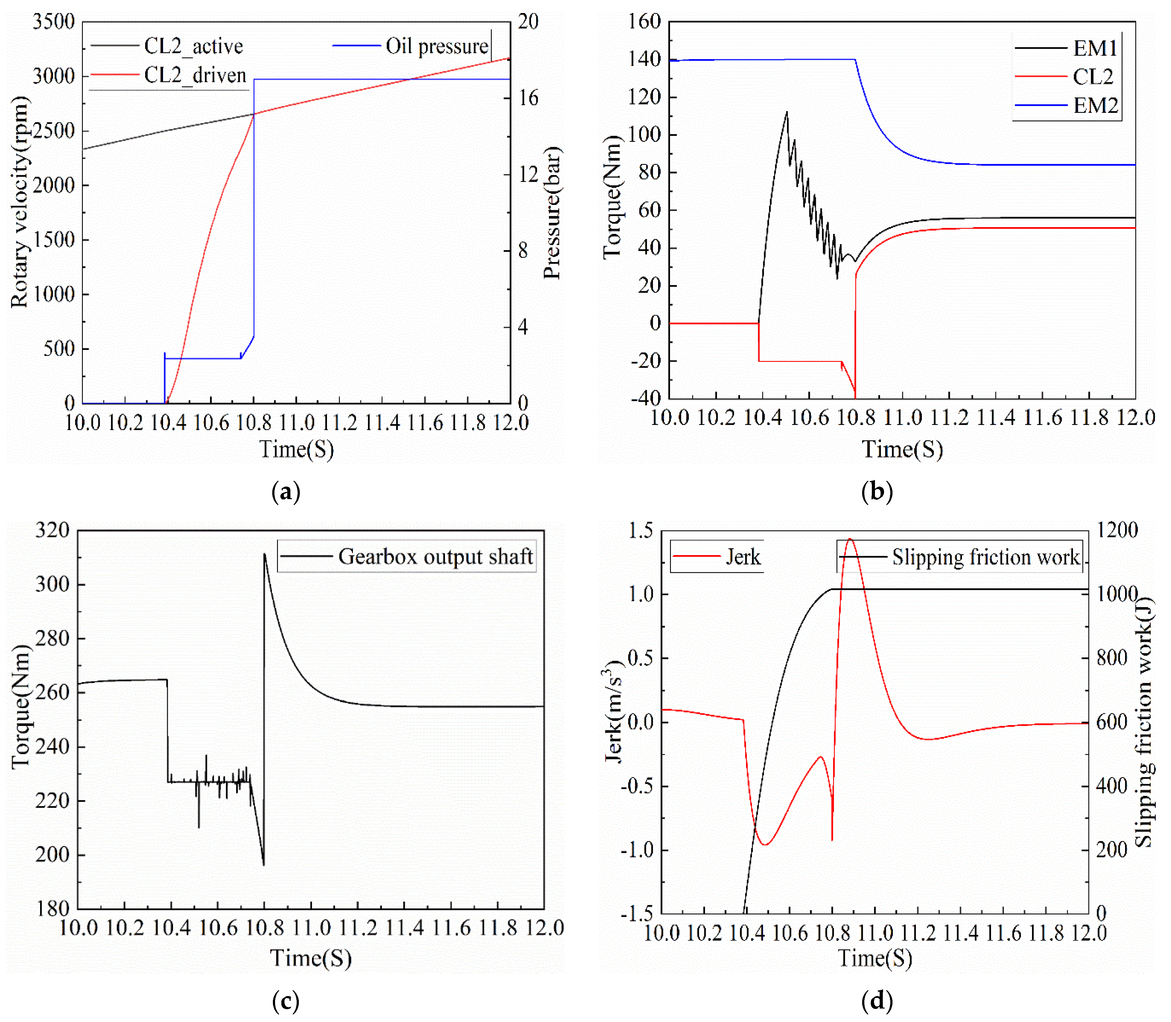
In this paper, a coordinated control strategy for shifting gears, based on motor rotary velocity regulation, is designed for the novel hybrid electric vehicle. Compared with the gear shift coordinated control strategy based on the PID control algorithm, the control strategy, based on the PID–bang-bang–fuzzy compound intelligent control algorithm proposed in this paper, reduced the shift time and clutch slipping friction work by 35.7% and 19.2%, respectively.

Author Contributions

Conceptualization, Q.X.; methodology, Q.X. and X.Z.; software, Q.X. and X.Z.; formal analysis, Q.X. and C.G.; investigation, C.G. and T.T.; data curation, Q.X. and X.Z.; writing—original draft preparation, Q.X. and X.Z.; writing—review and editing, Q.X., X.Z. and C.G.; visualization, C.G.; supervision, X.Z. All authors have read and agreed to the published version of the manuscript.

Funding

This research was funded by the National Key Research and Development Program of China (Grant No. 2017YFB0103203).

Institutional Review Board Statement

Not applicable.

Informed Consent Statement

Not applicable.

Data Availability Statement

The data provided in this study are available from the corresponding author.

Conflicts of Interest

The authors declare no conflict of interest.

Abbreviations

The following abbreviations are used in this manuscript: HEV, hybrid electric vehicle; EMS, energy management strategy; AMT, automated manual transmission; DCT, dual clutch transmission; ICE, internal combustion engine; EM1, electric motor 1; EM2, electric motor 2; CL1, clutch 1; CL2, clutch 2; CL3, clutch 3; SY, synchronizer; new European driving cycle, NEDC; PID, proportional-integral-derivative.

References

  1. Balali, Y.; Stegen, S. Review of energy storage systems for vehicles based on technology, environmental impacts, and costs. Renew. Sustain. Energy Rev. 2021, 135, 110185. [Google Scholar] [CrossRef]
  2. Laberteaux, K.P.; Hamza, K. A study on opportune reduction in greenhouse gas emissions via adoption of electric drive vehicles in light duty vehicle fleets. Transp. Res. Part D Transp. Environ. 2018, 63, 839–854. [Google Scholar] [CrossRef]
  3. Won, H.W. A Method and System for Combining the Advantages of Gasoline Compression Ignition (GCI) Engine Technologies into Hybrid Electric Vehicles (HEVs). Appl. Sci. 2021, 11, 9934. [Google Scholar] [CrossRef]
  4. Gu, J.; Zhao, Z.; Chen, Y.; He, L.; Zhan, X. Integrated optimal design of configuration and parameter of multimode hybrid powertrain system with two planetary gears. Mech. Mach. Theory 2020, 143, 103630. [Google Scholar] [CrossRef]
  5. Anselma, P.G.; Del Prete, M.; Belingardi, G. Battery High Temperature Sensitive Optimization-Based Calibration of Energy and Thermal Management for a Parallel-through-the-Road Plug-in Hybrid Electric Vehicle. Appl. Sci. 2021, 11, 8593. [Google Scholar] [CrossRef]
  6. Spano, M.; Anselma, P.G.; Misul, D.A.; Belingardi, G. Exploitation of a Particle Swarm Optimization Algorithm for Designing a Lightweight Parallel Hybrid Electric Vehicle. Appl. Sci. 2021, 11, 6833. [Google Scholar] [CrossRef]
  7. Cong, T.N.; Walker, P.D.; Nong, Z. Shifting strategy and energy management of a two-motor drive powertrain for extended-range electric buses. Mech. Mach. Theory 2020, 153, 103966. [Google Scholar]
  8. Dong, P.; Wu, S.; Guo, W.; Xu, X.; Wang, S.; Liu, Y. Coordinated clutch slip control for the engine start of vehicles with P2-hybrid automatic transmissions. Mech. Mach. Theory 2020, 153, 103899. [Google Scholar] [CrossRef]
  9. Zhou, J.; Xue, S.; Xue, Y.; Liao, Y.; Liu, J.; Zhao, W. A novel energy management strategy of hybrid electric vehicle via an improved TD3 deep reinforcement learning. Energy 2021, 224, 120118. [Google Scholar] [CrossRef]
  10. Singh, K.V.; Bansal, H.O.; Singh, D. Fuzzy logic and Elman neural network tuned energy management strategies for a power-split HEVs. Energy 2021, 225, 120152. [Google Scholar] [CrossRef]
  11. Zhang, L.; Yang, L.; Guo, X.; Yuan, X. Stage-by-phase multivariable combination control for centralized and distributed drive modes switching of electric vehicles. Mech. Mach. Theory 2020, 147, 103752. [Google Scholar] [CrossRef]
  12. Biswas, A.; Anselma, P.G.; Rathore, A.; Emadi, A. Effect of coordinated control on real-time optimal mode selection for multi-mode hybrid electric powertrain. Appl. Energy 2021, 289, 116695. [Google Scholar] [CrossRef]
  13. Fu, J.; Song, S.; Fu, Z.; Ma, J. Coordinated control strategy to reduce torque fluctuation for parallel hybrid electric vehicles. In Proceedings of the 2017 Chinese Automation Congress (CAC), Jinan, China, 20–22 October 2017; pp. 4181–4186. [Google Scholar] [CrossRef]
  14. Sim, K.; Oh, S.-M.; Namkoong, C.; Lee, J.-S.; Han, K.-S.; Hwang, S.-H. Control strategy for clutch engagement during mode change of plug-in hybrid electric vehicle. Int. J. Automot. Technol. 2017, 18, 901–909. [Google Scholar] [CrossRef]
  15. Zeng, X.; Yang, N.; Wang, J.; Song, D.; Zhang, N.; Shang, M.; Liu, J. Predictive-model-based dynamic coordination control strategy for power-split hybrid electric bus. Mech. Syst. Signal Process. 2015, 60–61, 785–798. [Google Scholar] [CrossRef]
  16. Liu, L.; Liang, X.; Zuo, M.J. Vibration signal modeling of a planetary gear set with transmission path effect analysis. Measurement 2016, 85, 20–31. [Google Scholar] [CrossRef]
  17. Yu, Z.; Hou, Y.; Leng, B.; Xiong, L.; Li, Y. Disturbance Compensation and Torque Coordinated Control of Four In-Wheel Motor Independent-Drive Electric Vehicles. IEEE Access 2020, 8, 119758–119767. [Google Scholar] [CrossRef]
  18. Zhang, F.-Q.; Hu, Y.-H.; Xi, J.-Q.; Li, Y. The Coordinate Control Strategy of Torque Recovery for the Parallel Hybrid Electric Vehicle. Asian J. Control 2016, 18, 40–54. [Google Scholar] [CrossRef]
  19. López, I.; Ibarra, E.; Matallana, A.; Andreu, J.; Kortabarria, I. Next generation electric drives for HEV/EV propulsion systems: Technology, trends and challenges. Renew. Sustain. Energy Rev. 2019, 114, 109336. [Google Scholar] [CrossRef]
  20. Wu, G.; Dong, Z. Design, analysis and modeling of a novel hybrid powertrain system based on hybridized automated manual transmission. Mech. Syst. Signal Process. 2017, 93, 688–705. [Google Scholar] [CrossRef]
  21. Wu, G.; Zhang, X.; Dong, Z. Powertrain architectures of electrified vehicles: Review, classification and comparison. J. Frankl. Inst. 2015, 352, 425–448. [Google Scholar] [CrossRef]
  22. Huang, W.; Huang, J.; Yin, C. Optimal Design and Control of a Two-Speed Planetary Gear Automatic Transmission for Electric Vehicle. Appl. Sci. 2020, 10, 6612. [Google Scholar] [CrossRef]
  23. Zhao, K.; Liu, Y.; Huang, X.; Yang, R.; Wei, J. Uninterrupted Shift Transmission and Its Shift Characteristics. IEEE/ASME Trans. Mechatron. 2013, 19, 374–383. [Google Scholar] [CrossRef]
  24. Walker, P.D.; Zhang, N. Active damping of transient vibration in dual clutch transmission equipped powertrains: A comparison of conventional and hybrid electric vehicles. Mech. Mach. Theory 2014, 77, 1–12. [Google Scholar] [CrossRef]
  25. Lei, Z.; Sun, D.; Liu, Y.; Qin, D.; Zhang, Y.; Yang, Y.; Chen, L. Analysis and coordinated control of mode transition and shifting for a full hybrid electric vehicle based on dual clutch transmissions. Mech. Mach. Theory 2017, 114, 125–140. [Google Scholar] [CrossRef]
  26. Gao, B.; Liang, Q.; Xiang, Y.; Guo, L.; Chen, H. Gear ratio optimization and shift control of 2-speed I-AMT in electric vehicle. Mech. Syst. Signal Process. 2015, 50–51, 615–631. [Google Scholar] [CrossRef]
  27. Yu, C.-H.; Tseng, C.-Y. Research on gear-change control technology for the clutchless automatic–manual transmission of an electric vehicle. Proc. Inst. Mech. Eng. Part D J. Automob. Eng. 2013, 227, 1446–1458. [Google Scholar] [CrossRef]
  28. Tseng, C.-Y.; Yu, C.-H. Advanced shifting control of synchronizer mechanisms for clutchless automatic manual transmission in an electric vehicle. Mech. Mach. Theory 2015, 84, 37–56. [Google Scholar] [CrossRef]
  29. Mo, W.; Wu, J.; Walker, P.D.; Zhang, N. Shift characteristics of a bilateral Harpoon-shift synchronizer for electric vehicles equipped with clutchless AMTs. Mech. Syst. Signal Process. 2021, 148, 107166. [Google Scholar] [CrossRef]
  30. Walker, P.; Zhu, B.; Zhang, N. Powertrain dynamics and control of a two speed dual clutch transmission for electric vehicles. Mech. Syst. Signal Process. 2017, 85, 1–15. [Google Scholar] [CrossRef] [Green Version]
  31. Li, L.; Wang, X.; Xiong, R.; He, K.; Li, X. AMT downshifting strategy design of HEV during regenerative braking process for energy conservation. Appl. Energy 2016, 183, 914–925. [Google Scholar] [CrossRef]
Figure 1. Schematic of structure of novel HEV.
Applsci 11 12118 g001
Figure 2. The efficiency MAP of the electric machine. (a) EM1; (b) EM2.
Applsci 11 12118 g002
Figure 3. Map of motor power loss. (a) EM1; (b) EM2.
Applsci 11 12118 g003
Figure 4. Simulation results based on NEDC conditions.
Applsci 11 12118 g004
Figure 5. Shift control flow chart of gears 01–11.
Applsci 11 12118 g005
Figure 6. Schematic of control principle, based on PID algorithm.
Applsci 11 12118 g006
Figure 7. Schematic of control principle based on PID–bang-bang compound algorithm.
Applsci 11 12118 g007
Figure 8. Schematic of control principle, based on PID–bang-bang–fuzzy compound intelligent algorithm.
Applsci 11 12118 g008
Figure 9. Membership functions of input and output variables.
Applsci 11 12118 g009
Figure 10. Fuzzy control rules surfaces of output variables. (a) ΔKp, (b) ΔKi, (c) ΔKd.
Applsci 11 12118 g010aApplsci 11 12118 g010b
Figure 11. Schematic of coordinated control strategy for motor and clutch.
Applsci 11 12118 g011
Figure 12. Membership functions of input and output variables. (a) Membership function of accelerator pedal opening; (b) membership function of change rate of accelerator pedal opening; (c) membership function of initial oil pressure change.
Applsci 11 12118 g012aApplsci 11 12118 g012b
Figure 13. Fuzzy control rule surface of CL2 initial oil pressure change.
Applsci 11 12118 g013
Figure 14. Schematic diagram of co-simulation platform.
Applsci 11 12118 g014
Figure 15. Rotary velocity regulation effect of PID algorithm under different target rotary velocities.
Applsci 11 12118 g015
Figure 16. Rotary velocity regulation effect of PID–bang-bang compound algorithm under different target rotary velocities.
Applsci 11 12118 g016
Figure 17. Rotary velocity regulation effect of PID–bang-bang–fuzzy compound intelligent algorithm under different target rotary velocities.
Applsci 11 12118 g017
Figure 18. Effect of algorithm threshold on rotary velocity regulation.
Applsci 11 12118 g018
Figure 19. Comparison of different control algorithms.
Applsci 11 12118 g019
Figure 20. Simulation conditions.
Applsci 11 12118 g020
Figure 21. Rotary velocities of active and driven ends of CL2.
Applsci 11 12118 g021
Figure 22. Simulation results based on PID control algorithm. (a) Rotary velocity and pressure of CL2; (b) torque of power source and CL2; (c) output torque of gearbox output shaft; (d) jerk and slipping friction work.
Applsci 11 12118 g022
Figure 23. Simulation results based on PID–bang-bang–fuzzy compound intelligent control algorithm. (a) Rotary velocity and pressure of CL2; (b) torque of power source and CL2; (c) output torque of gearbox output shaft; (d) jerk and slipping friction work.
Applsci 11 12118 g023
Table 1. Main parameters of novel HEV.
ComponentItemValue/Unit
VehicleVehicle mass1545 kg
Wheel radius0.347 m
Drag coefficient0.36
Rolling resistance coefficient0.008
Windward area2.638 m2
ICEMaximum power110 kW
Maximum torque210 Nm
Operating speed range700–5500 rpm
EM1Peak torque160 Nm
Peak power55 kW
Peak speed6200 rpm
EM2Peak torque155 Nm
peak power70 kW
Peak speed12,000 rpm
GearboxFirst gear ratio2.03
Second gear ratio1.1
Three gear ratio0.63
Main reducerGear ratio3.9
Table 2. Working modes of combined gears.
SYCL2CL3Gear PathID
EM1EM2
1000101
1012121
1101111
111XXX
N000000
N012020
N100000
N112222
3000303
3012323
3103333
311XXX
Table 3. Main parameters of wet clutch.
ClutchCoefficient of FrictionNumber of Friction SurfacesOuter Diameter of Friction Surface/mmInner Diameter of Friction Surface/mm
CL10.128129108.1
CL20.1210120.1107
CL30.1212126.7110.8
Table 4. Main parameters of hydraulic cylinder.
Clutch Hydraulic
Cylinder
Piston Diameter/mmPiston Rod Diameter/mmPiston Stroke/mmMaximum Force on Piston/N
CL1 603028984
CL2 45251.35779.94
CL3 45251.56027.34
Table 5. Comparison of characteristics of motor rotary velocity regulation control algorithms.
Control AlgorithmAdvantagesDisadvantages
PIDThe principle of the algorithm is simple;
Effective control can be achieved even when the model of the controlled object is not known.
Conventional PID algorithm is prone to problems such as excessive adjustment time and excessive overshoot;
The ability to adapt to model parameter changes and interference is poor.
Bang-bangResponse time is fast.It is easy to cause overshoot and fluctuation and reduce the system accuracy. The steady-state error is large.
Fuzzy logicFuzzy controller has good robustness and does not depend on accurate mathematical model.
It is suitable for nonlinear and large time-delay control systems.
There is static error;
Poor tracking quality.
PID–bang-bang–fuzzyPID–bang-bang–fuzzy composite controller has good quality in robustness, steady-state error and dynamic tracking performance.The structure of the control algorithm is complex.
Table 6. Comparison of shift evaluation indexes.
Gear Shift Control StrategyShift TimeMaximum JerkCL2 Slipping Friction Work
Based on PID0.42 s1.46 m/s31017 J
Based on PID–bang-bang–fuzzy0.27 s3.77 m/s3821.3 J
Publisher’s Note: MDPI stays neutral with regard to jurisdictional claims in published maps and institutional affiliations.

