Article

Field Treatment of Storage Sludge and Stability Analysis of Overlying Municipal Waste Landfilling

1
MOE Key Laboratory of Soft Soils and Geoenvironmental Engineering, Institute of Geotechnical Engineering, Zhejiang University, Yuhangtang Road 866#, Hangzhou 310058, China
2
Center for Hypergravity Experiment and Interdisciplinary Research, Zhejiang University, Hangzhou 310058, China
*
Author to whom correspondence should be addressed.
Appl. Sci. 2021, 11(24), 12102; https://doi.org/10.3390/app112412102
Submission received: 3 November 2021 / Revised: 14 December 2021 / Accepted: 16 December 2021 / Published: 19 December 2021

Abstract

:
Storage sludge has high water content and low shear strength, which limits the capacity expansion of overlying municipal landfilling. Few studies have addressed the field treatment of large amounts of storage sludge due to the variability of the depth of geotechnical property. This paper proposes a stratified treatment method for storage sludge, based on the in situ characterization of layered sedimentary patterns of the storage sludge acquired from the Qizishan landfill in China. Additionally, the stability of the landfilling above the sludge pond is analyzed using the Morgenstern–Price and limit equilibrium slice method, which considers the layered strength properties of solidified sludge. The treated sludge has a significant decrease in average water content from 1398% to 88% and an increase in average cohesion to 23.52 kPa. The high content of clay particles, low amount of solidification products, and high water content together result in the high sensitivity to the water content of the strength of deep solidified sludge. For a 40-m high waste body, stability analysis suggests a sliding surface across the raw sludge pond, while the critical surface remains outside the treated sludge pond and the safety factor is increased from 0.934 to 1.464. The validated stratified treatment provides valuable references for the treatment of deep sludge.

1. Introduction

Sludge is the semisolid residue that is produced as a by-product during the sewage treatment of industrial or municipal wastewater [1]. The total sewage treatment in the urban cities and towns of China had an average annual growth of 10% from 2001 to 2015, and the treated sewage in 2015 was 428.83 × 10⁸ m3. The early sewage treatment pays more attention to the sewage rather than the sludge, which leads to the sludge being simply piled or buried in the environment and becoming storage sludge [2]. There is a large amount of storage sludge in China. For example, the Laogang landfill in Shanghai received 1.28 million tons of sludge from 2012 to 2015; the Xiaping landfill in Shenzhen accommodated about 1.21 million tons of municipal sewage sludge; 1.5 million tons of sludge generated by the Shenyang sewage treatment plants was piled in Zhujia Town, Shenyang [3]. For the early treatment of the storage sludge before landfilling, the treatment method most frequently used is limited to conventional mechanical dehydration [4]. The conventional mechanical dehydration merely removes the free water as well as some of the interstitial water from the sludge, which results in a remaining water content of over 400% in the treated sludge. Due to the high water content, organic matter content, and plasticity, storage sludge presents low strength [5]. This contributes to the low bearing capacity of the foundation formed by the raw sludge and can cause the instability of the overlying landfill slope, thereby endangering its operation [6,7]. Thus, the landfills with high storage sludge stockpiles pose potential safety hazards in capacity expansion. Therefore, it is urgent that the raw storage sludge is treated in order to enhance its strength and ensure the stability of the waste slopes above.
There are several kinds of treatment available for enhancing the raw sludge at present. They include vacuum preloading dehydration, chemical conditioning combined with vacuum preloading, and solidification. Vacuum preloading decreases the water content and improves the strength of the sludge by setting vertical drainage channels and covering the sand cushion above the sludge to form a sealing film [7,8]. Zhan [9] explored the sludge dehydration via vacuum preloading model tests and found that the average shear strength of the dewatered sludge increased from 0.3 kPa to 2–4 kPa. The chemical preconditioning of the sludge transforms part of the bound water to free water, which promotes dehydration [10,11,12,13]. Zhan [9] used FeCl3 with a dosage of 10% as the conditioner and drainage plates with a spacing of 0.4 m for combined dehydration. Results showed that the undrained shear strength of the sludge with a water content of 142% increased to 10 kPa. For sludge solidification, the most common solidifying materials are cement, lime, and fly ash. It is widely acknowledged that solidification decreases the water content of the sludge and enhances its strength by constructing a skeleton structure [7,14,15,16,17,18]. Legiec et al. [19] solidified an industrial sludge lagoon and tested the in situ solidified sludge and found that the unconfined compressive strength of the solidified sludge with a water content of 150% reached 206.80 kPa by mixing it with 22% of Portland cement. From a throughout analysis of the different sludge treatment methods, the vacuum preloading reduced the water content of sludge but did not obviously improve its strength. Similarly, the chemical conditioning combined with vacuum preloading had more dramatic reductions in water content, but the strength improvement was not significant either. The solidification produces hydration products that consume the water and connect the soil particles to the sludge, and as a result, the solidified body has a significant strength enhancement. In conclusion, solidification is comprehensively the best method in the strengthening and decrease in water content of the sludge.
However, because of the complex characteristics of sludge ponds, the physical properties of the storage sludge should be determined prior to choosing a sludge treatment, especially in sludge ponds with a large volume and high buried depth. The large volume can greatly increase the variability of the physical properties across the pond. Thus, it is necessary to carry out a detailed field investigation, as well as a physical characterization of the storage sludge. Additionally, the high buried depth translates into differences in the physical characteristics of the sludge due to the sludge composition, age, and confining pressure. It is common that a raw sludge pond can be subdivided into layers by the layered sedimentation [3]. Due to the variability in properties, using a single treatment method appears to be ineffective. Therefore, combined sludge treatments should be explored for the disposal of sludge ponds with large volumes and high buried depths.
The ultimate problem that needs to be addressed in order to expand the capacity of landfills is the stability of the slope piled above the sludge pond. Zhan et al. [20] analyzed the failure mechanism of an unstable waste slope, which contained a sludge pond, in a Chinese landfill. They pointed out that many factors, including the height of the waste body above the sludge pond, the strength of the sludge, and the leachate level in the slope body, affect the stability of the slope. Some researchers studied the stability of a slope formed by heaped dewatered or solidified sludge [21,22]. Nevertheless, there are few studies that have investigated the slope stability of landfills constructed above a solidified sludge pond. The particular characteristics of the sludge and its variability within the pond require the use of the shear strength field data, representative of the different zones and depths of the sludge, to analyze the stability of the waste slopes above the pond.
To sum up, with a comprehensive consideration of the physical characteristics of the raw storage sludge and the effectiveness of the field treatment, this paper proposes an in situ stratified treatment. Additionally, physical property tests were undertaken on the solidified sludge to evaluate the water content and strength, and to analyze the stability of the overlying waste slope. The aforementioned sludge management provides a reference significance for securely expanding the capacity of the landfill.

2. Raw Storage Sludge Characterization

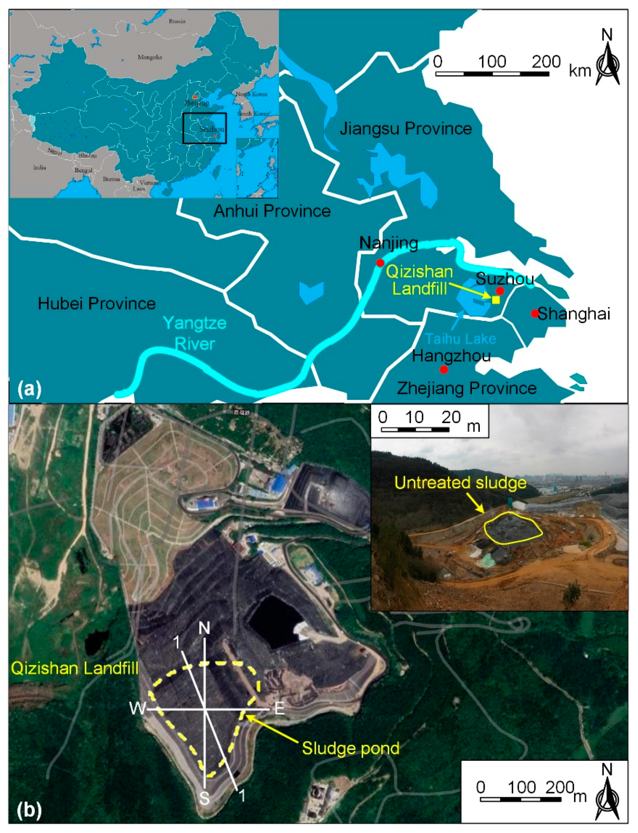
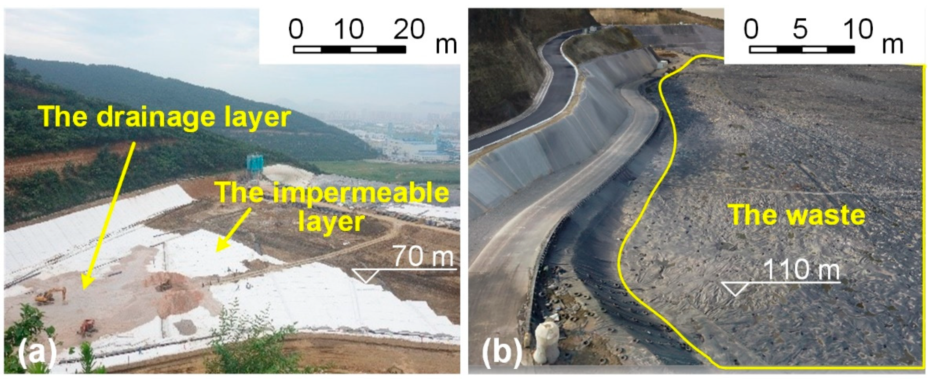
2.1. Site Description

The Qizishan landfill is located in the foothills of the Qizishan Mountain, Suzhou, China (Figure 1a). The first phase of the Qizishan landfill had a design capacity of 4,700,000 m3. With the total annual amount of waste increasing, an extension project of the landfill was carried out based on the first phase of the landfill. The horizontal and vertical landfilling areas were both expanded to create a new landfilling zone and formed a sludge pond, which now covers an area of 21,000 m2 and is located in the southwestern part of the Qizishan landfill (Figure 1b). At the time of sludge pond treatment, the site investigation showed that the sludge volume of the pond was about 230,000 m3. In the sludge pond, the width of the north–south section was 180 m and the width of the east–west section was 160 m (Figure 1b).

2.2. Field Sampling

The drill hole sampling and field tests were carried out in the sludge pond for the field and laboratory investigations on the physical properties of the sludge (Figure 2). The drill hole sampling of the raw storage sludge was carried out at the point positions of ZK02-ZK22. These positions were along the north–south section as well as the east–west section, and were spread all over the sludge pond. The cone penetration tests (CPT) and the vane shear tests on the pond were carried out around the point position of C1-C5 and V1-V5, respectively. Considering the surface of the sludge pond had an extremely low strength, a floating platform built from the empty tanks was set to act as a working platform [3].
From further observation of the samples from boreholes, the sludge pond could be divided into the mud-water mixing layer, fluid-like sludge layer, and fluid–plastic sludge layer, from top to bottom. The representative sections of the north–south section, east–west section, and Profile 1-1 of the sludge pond are shown in Figure 3. The reason Profile 1-1 was chosen as the representative section is listed as follows: (1) the aerial view of the landfill (Figure 1) shows that the landfill mainly trends north–south, and the elevation of the east–west section of the landfill is invariable, therefore, the selection of the section along the north–south needed to be ensured as far as possible; (2) the gradient of the slope body, which was constructed by the waste and situated downstream of the sludge pond, along Profile 1-1 is the largest in the entire waste slope and prone to occur instable failure; and (3) in the sludge pond, the obvious water and mud demarcation, using the average water content of 1000% as the water and mud demarcation value of the sludge (Figure 2), and the chosen cross profile needed to contain as much watery sludge as possible. Figure 3 indicates that the buried depth of the first layer ranged from 0 to 7.5 m and had an average thickness of 3.1 m. That layer contained sludge particles and water, which mainly resulted from the rainfall and the water in the raw storage sludge. Additionally, a fluid–plastic layer was observed below the depth of 4.5 m and had a thickness ranging from 2.0 m to 9.7 m, with an average of 5.5 m. The formation of this layer was related to the self-weight consolidation of the raw storage sludge. Lastly, the fluid-like layer was similar to a slurry and had a thickness ranging from 6 m to 16.5 m, with an average of 7.6 m. That layer was the transition layer of the mud–water mixing layer and the fluid–plastic layer. The distribution of the layers among the sludge pond revealed that the heavy particles of raw sludge deposited downward, and the detailed physical properties caused by the sedimentation will be further discussed later in this paper.

2.3. Physical Properties

In this study, water content is defined as the ratio of the water’s mass to the dry solids’ mass. It was determined using the oven-drying method, according to ASTM procedure D2974-14 [23]. To prevent the carbonization and oxidation of the organic matter in the sludge during the drying process, the drying temperature was controlled at 65 °C. Figure 4 illustrates the variance of the water content, which was measured from the raw storage sludge samples taken from the sludge pond, as well as the depth. The water content ranged from 172% to 7270%, with an average of about 1397%. The water content of the raw storage sludge within the same depth presented several different values. The reason for this is that, among the whole pond, the historical origin and conditions of the raw sludge were different. The average water content showed a fluctuating downward trend along with the depth. The reason for this is the sludge pond had an irregular depth, with a deep center and a shallow edge, rather than a constant depth. Related to the aforesaid appearance stratification, the water content showed a general decreasing trend along with the depth. This is because the large particles settled to the bottom of the pond while the slower sedimentation velocities of the fine particles kept them in the upper regions, resulting in the increase in the solid content of the sludge as the depth increased [20]. The variation of water content and its depth in the sludge pond is first discussed in two zones, namely the watery sludge zone (ZK10-ZK11, ZK16-ZK22) and the muddy sludge zone (ZK02-ZK09, ZK12-ZK15), which is shown in Figure 2. The large difference in the water content between the two zones was related to the topography of the bottom of the sludge pond and the location of the sludge dumping. The water content in the muddy sludge zone was almost all less than 1000%. This is due to the location of the sludge dumping in the watery sludge zone and the earlier deposit of sludge in zones I and II. The water content of ZK02-ZK06 in zone I varied less with the depth, while the water content of ZK08, ZK09, and ZK12-ZK15 in zone II decreases significantly with increasing depth. This is because zone I was shallower than zone II. The water content of the sludge in the muddy sludge zone was generally high, and the water content of ZK10, ZK11, ZK18, and ZK19 within zone III varied less with the depth, while the water content of the remaining boreholes within zone IV varied significantly with the depth. This zoning situation correlated with the sludge dumping location at the edge of zone IV.
The apparatus used for the CPT was a double bridge cone penetrometer, the probe was equipped with a cone-shaped tip (an apex angle of 60°), and the penetration rate of the probe was fixed at 1.20 m/min. The CPT procedure was according to ASTM D3441 [24]. Figure 5 shows the tip resistance and sleeve friction plots obtained from the CPT (C1-C5). The maximum values of the tip resistance and sleeve resistance of the raw storage sludge were both less than 50 kPa and much lower than that of the ordinary soft clay, whose tip resistance and friction resistance typically ranges from 100–700 kPa [3]. Moreover, the CPT readings of the three layers in the sludge pond were related to the stratified appearance and the stratified rule was different in each test position. Firstly, at depths of 0–8 m in C1 and C3, 0–17.4 m in C2, in 0–7.4 m in C4, 0–11 m in C5, the CPT values of the sleeve resistance and the tip resistance were essentially close to zero. This conforms to the appearance of mud–water mixing. Secondly, between the depths of 8 m and 10 m in C1 and C3, the depths of 17 m and 19 m in C2, the depths of 7.4 m and 15.3 m in C4, and the depths of 11 m and 12.5 m in C5, the CPT readings of the tip resistance and sleeve resistance slightly increased with the depth. This indicates that this layer was a fluid-like sludge layer. Thirdly, below the fluid-like sludge layer, at depths of 10–10.7 m in C1, 19.4–19.7 m in C2, 10–12 m in C3, 15.3–22 m in C4, and 12.5–13.1 m in C5, the CPT readings showed a significant increase with the increasing depths. This means that the sludge was in a fluid–plastic layer. It is worth noting that the CPT tests at location C1 revealed that at 11.3 m, the probe rod began to bend, presumably because this depth was the location of the interface between the mountain and the bottom of the sludge pond. Additionally, it should be noted that the sampling point of C2 was the center of the raw sludge pond and the bottom surface shape of the pond influenced the sedimentation of the sludge, which contributed to the different stratification thickness in C2 from other points.
The apparatus used for the vane shear test was the vane of 50 mm × 100 mm × 2 mm (diameter × height × thickness) and the test procedure was according to ASTM D2573 [25]. Figure 6 shows the change of the undrained shear strength of the raw storage sludge with the corresponding depth in the sludge pond. The undrained shear strength of the raw storage sludge within the buried depth of 8 m or 9 m was about 0.1–1.9 kPa at V1, V3, V4, and V5. Within the buried depth of 17 m at V2, the raw sludge presented the undrained shear strength of 0.2–1.1 kPa. The distribution of these strength values is consistent with the mud–water mixing appearance of the aforementioned depth range. As the buried depth increased, the undrained shear strength increased slightly and the appearance of the sludge showed as a slurry. The raw storage sludge at V1, V3, V4, and V5, with the buried depths of 12 m or 13 m, had the maximum undrained shear strength of 4.1–14.9 kPa. The raw storage sludge at V2 with a buried depth of 18 m had a maximum undrained shear strength of 4.7 kPa. In addition, below the aforementioned buried depths, the tested undrained shear strengths presented an obvious increase with the depth. The undrained shear strength of the raw storage sludge with the specified buried depth is listed as follows: the buried depth of 14 m at V1 was 11.2 kPa, the buried depth of 19 m at V2 was 10.9 kPa, the buried depth of 12 m at V3 was 12.7 kPa, the buried depth of 11 m at V4 was 14.6 kPa, and the buried depth of 13 m at V5 was 14.9 kPa. These strength values correlated with self-weight consolidation and were consistent with the appearance of the fluid–plastic.
The sampling and field tests indicated that the sludge within the depth of 0–9 m was a mud–water mixing layer. The raw sludge in the fluid–plastic layer had a thickness ranging from 2.0 m to 9.7 m, and the minimum buried depth of that was 4.5 m. Additionally, the other areas of the hole positions were in the fluid-like layer. That indicates that the sludge pond was irregular in depth, with a deep center and a shallow edge, rather than a pond of equal depth.

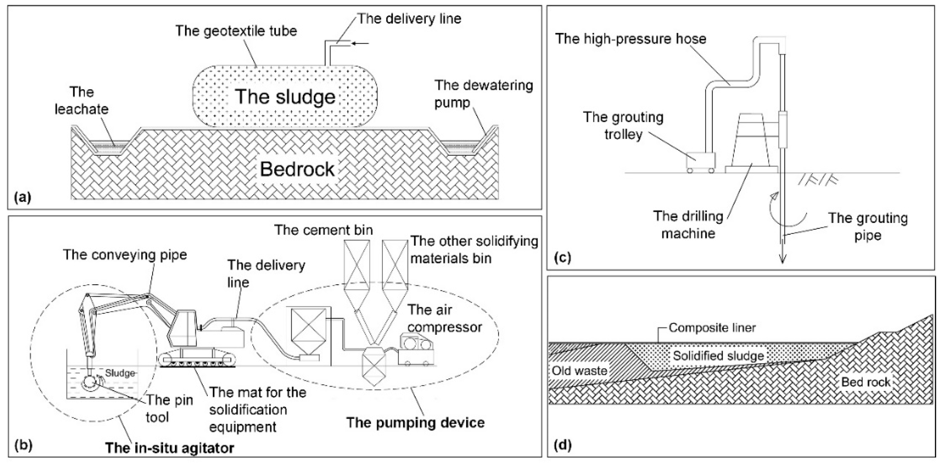
3. Stratified Treatment of Storage Sludge

The field sampling and laboratory test results reveal that the sludge pond at the Qizishan landfill is divided into a mud–water mixing layer, fluid-like sludge layer, and fluid–plastic sludge layer, from top to bottom. The water content test of the raw storage sludge showed a decreasing trend with the depth, and that the values maintained a high level. Correspondingly, the strength of the raw storage sludge increased with depth, and the values maintained an extremely low level. Simultaneously, considering the large volume and high buried depth of the sludge pond at the Qizishan landfill, the stratified treatment was adopted for the sludge pond (Figure 7). First, the sludge in the mud–water mixing layer was dehydrated using an ex situ geotextile tube. Second, due to the layered sedimentation of the raw sludge in the pond, the in situ solidification by stirring was applied in the shallow sludge, whose buried depth was less than 10 m. Finally, the high-pressure chemical churning pile was utilized in the deep sludge, which was located at buried depths of more than 10 m. This technique is quite effective in improving the shear strength of the foundation, which is formed of silt, mucky soil, liquid-plastic clayey soil, and soft-plastic clayey soil [26]. In-situ stirring solidification requires: (1) sampling of the sludge to analyze its physical properties and designing the solidifying agent formulation; (2) dividing the grid and measuring the depth according to the working area to calculate the dosage of the solidifying agent; (3) arranging the types and numbers of solidifying equipment and solidifying route. The high-pressure chemical churning pile applied in the sludge needs to test the pile-forming before construction, and the technical parameters, such as slurry ratio, injection pressure, and slurry volume, are determined according to the actual situation in the field. Where the calculation and design process need to use the physical properties of the sludge cannot be replaced by improving the method, while the actual treatment operation can improve the efficiency of the treatment by improving the process.
The sludge from the mud–water mixing layer was pumped into the geotextile tube using a submersible mud pump. There were 20,000 m3 of sludge treated by dewatering in the geotextile tube in 40 days. To improve the dehydration effect, a flocculant was added to the sludge. It should be noted that the content of the admixture is defined as the wet mass ratio of the solidifying materials to the sludge. In the dehydration of sludge, the polyaluminium chloride (PAC) and polyacrylamide (PAM) are widely used for flocculation [27,28]. For each 1 m3 of sludge, 1200 g of 1.7% PAC and 200 g of 0.05% PAM were added simultaneously. The mix was conveyed to the snake-like pipe, which was used for increasing the contact time of the sludge, as well as the flocculant, and enhancing the flocculation effect of the sludge, and then it was pumped into the geotextile tube for dehydration (Figure 8a). The strong pressure inside the geotextile tube effectively dewatered the sludge and held the solid particles [29].
In the shallow sludge, 110,000 m3 of fluid-like sludge was solidified by in situ agitation in 131 days. The solidifying materials were pumped into the sludge pond using in situ curing stirring equipment. The addition of a chemical conditioner transformed part of the bound water into free water, allowing further dewatering. Thus, based on the pilot tests, the formula of the solidifying materials was optimized by adding chemical conditioners. The final formula is shown in Table 1. The in situ curing stirring equipment included an in situ stirring device, a solidifying material mixing device, and a pumping device (Figure 8b). The key part of the in situ curing stirring equipment was the in situ stirring device, which was composed of a conveying pipe, a pin tool, and a long-reach excavator. The long-reach excavator’s telescopic boom continuously transported the solidifying materials through the conveying pipe, which was equipped with a pin tool, into the sludge pond. The pin tool, which was a hollow spiral, was equipped with a specially made horizontal roller and stirring parts. Due to the large power and torque of the in situ agitator, the pin tool moved discretionarily based on the deflection of the long arm of the excavator, and it fully mixed the solidifying materials with the sludge to form a solidified body.
In the deep layer sludge, the technology of the high-pressure chemical churning pile was used for 74,000 m3 of fluid–plastic sludge in 50 days. The drill was placed at the specific hole site, and then it drilled to the target depth. The dual-channel double grouting pipes, which were equipped with a special nozzle, were simultaneously brought to the specified depth. At the same time, the coaxial dual nozzle, which was located at the bottom of the conveying pipe, jetted slurry with a pressure of 25 MPa and air with a pressure of 0.70 MPa. The sludge’s structure was destroyed by the slurry and the air, and the solidification body was formed of the mixture of sludge particles and slurry. The grouting pipe was rotated and lifted to the final elevation slowly during the rotary spraying (Figure 8c). The grouting pump, grouting pipe, and drill pipe were washed at the end of a single rotary spraying. Then, the next grouting pile was built. The above processes were repeated until the rotary jet piles were completed in the sludge pond. The slurry sprayed in the rotary spraying was cement slurry, which was prepared using ordinary Portland cement with a water–cement ratio of 1, and the content of ordinary Portland cement in the sludge was 25%. The diameter of the high-pressure chemical churning piles was 1 m. The length of the piles, which entered the solidified sludge layer and the old waste layer, was 1 m. The average depth of the piles was more than 10 m. The cement slurry volume of a single pile was greater than 3.1 m3. The lifting speed was 0.20 m·min−1, and the rotation speed was 11–14 r·min−1. The layout of the high-pressure chemical churning pile was a regular triangle, with 3-m long sides, and the replacement rate was 10%.
To prevent the infiltration of rainfall, an impervious layer of 1.0 mm LLDPE geomembrane was set on the surface of the solidified sludge pond. Additionally, a drainage layer, which was formed of the crushed stone, was placed above the impervious layer. These two layers formed a composite liner (Figure 8d and Figure 9a). After 28 days of the stabilization of the last treated sludge, the liner system was built above the treated sludge pond.

4. Analysis of the Solidified Sludge

4.1. Field Sampling

The water content of the sludge treated by the geotextile tube was designed to reduce to 400% for the subsequent solidification. Furthermore, the dehydration effect of the sludge treated by the geotextile tube was easily measured. However, the sludge treated by the in situ solidification was hard to measure in a unified way. Thus, the physical characteristics of the solidified sludge were analyzed emphatically. The field sampling was carried out at the solidified sludge pond after the curing time reached 28 days. To test the distribution of the physical properties along Profile 1-1 (Figure 1), the samples taken from the positions of ZK01, ZK02, ZK03, ZK05, ZK14, ZK10, ZK18, and ZK23 were analyzed emphatically.
There were three types of solidified sludge appearances in the sludge pond (Figure 10). The solidified sludge that appeared to be solid was similar to clay, with low water content and high compactness. The solidified sludge that appeared to be plastic was similar to clay with low water content. The solidification effect of the sludge that had a soft-plastic state was worse than that of the plastic sludge, which was reflected in the water content and compressibility. The appearance of the samples along Profile 1-1 showed the solidified sludge pond stratification (Figure 10). Different samples presented variable stratification along Profile 1-1, indicating a non-uniform solidification in the pond. The difference in the solidification results above and below a depth of 10 m showed the different effectiveness of the in situ techniques, i.e., stirring and high-pressure chemical churning. The high-pressure chemical churning improved the strength of the sludge pond by utilizing the combined action of the pile-forming and the sludge between the piles. So, the appearance of the solidified sludge in different locations of the sludge pond differed below a depth of 10 m. The lack of fine control and real time monitoring of the in situ equipment led to the poor uniformity of the solidification in the sludge pond.
According to Figure 10, the solidified sludge at the positions ZK01, ZK02, ZK03, and ZK05 appeared generally solid-like, hence, presented an excellent solidification effect. These positions were located in the south of the sludge pond, and the water content of the raw storage sludge in these positions was lower than that of the raw storage sludge in the north of the sludge pond, such as the positions ZK10, ZK14, ZK18, and ZK23. The solidified sludge, with buried depth ranges of 6–10 m in borehole ZK01, 4–6.5 m in borehole ZK03, and 2–10 m in borehole ZK05, appeared to be in a plastic state due to the in situ stirring operation. At the position of ZK05, the solidified sludge appeared to be in a solid-like state at a depth of 2 m, benefited by sufficient operating capacity and proper operation of the in situ curing stirring equipment. In addition, 10–21-m deep solidified sludge was in a soft-plastic state, caused by the operation of the high-pressure chemical churning pile. The solidified sludge of the upper part, at ZK10, ZK14, ZK18, and ZK23, was in at least a plastic state, except the solidified sludge which appeared in a soft-plastic state in the ranges of 6–10 m at ZK05 and 4–10 m at ZK18. This may be due to the solidification of the upper area, whose buried depth was within 10 m, not being completed or the curing agent not reaching the specified depth. The solidified sludge at ZK10, ZK14, ZK18, and ZK23, whose buried depth was over 10 m, was in the plastic state or soft-plastic state. This is because the solidified sludge in these positions showed different distances from the jet grouting piles and the samples in different depths were in a different confining condition for the non-uniform piles. In general, the solidification of the sludge pond could be stratified into two parts, bounded by a buried depth of 10 m.

4.2. Physical Properties

In addition to the field measurements, laboratory tests, which revealed the water content and strength of the treated sludge, allowed for the further characterization of the physical properties of the samples. The solidified sludge field samples tested in the laboratory were in undisturbed conditions.

4.2.1. Water Content

Figure 11 shows the variation of the water content with the depth. The water content of the solidified samples mainly ranged from 39% to 156%. Compared to the water content of raw storage sludge, that of the solidified sludge decreased significantly. The solidification directly decreased the water content of the sludge by hydration reaction and evaporation, so the variation in water content reflects the level of solidification. The water content distribution of the solidified sludge pond was irregular. Based on the layered appearance by the field sampling (Figure 10), the water content analysis of the two parts of the solidified sludge, which included the samples within a 10-m depth and below 10 m, was evaluated. The solidified sludge with buried depths of less than 10 m ranged from 39% to 134% of water content and had an average water content of 83%. The solidified sludge at 2 m had the lowest mean water content at 65%, and the solidified sludge at 10 m had the highest water content at 114%. The water content of the solidified sludge within a depth of 6 m was lower than that of a 6 m to 10 m depth, at 73% and 100.08%, respectively. In the in situ solidification by stirring, the telescopic boom was 6 m in length, which led to the previous water content distribution. For the deep zone of the solidified sludge pond, with a buried depth greater than 10 m, the water content of the solidified sludge ranged from 69% to 156%, and the mean water content value of every depth fluctuated around 100%. The average water content of the deep solidified sludge below 10 m was 99%, which was higher than that of the solidified sludge within 10 m at 83%. The high-pressure chemical churning piles enhanced the bearing capacity of the solidified sludge pond and did not always decrease the water content of the sludge in the working area. Thus, the water content of the solidified sludge below 10 m was higher than that of the solidified sludge within 10 m. Additionally, the variance of the water content value between the solidified sludge within and below 10 m was due to the solidification mechanism. The solidified sludge within a 10 m buried depth finished solidification in the whole pond, whereas the inhomogeneous solidification effect led to water contents with a large standard deviation of 29%. While below a 10 m buried depth, the cement slurry squeezed into the surrounding sludge and became the solidified body of cement slurry–sludge. Under the layout of the high-pressure chemical churning pile, with a regular triangle of 3-m long sides, the cement slurry squeezed into the surrounding of the piles due to the high pressure. Thus, the water contents of this layer maintained a small difference, with the standard deviation of 23%, for similar water consumption of the cement slurry solidification.

4.2.2. Strength Properties

Direct shear tests were conducted according to AASHTO procedure T236-08 [30]. The sheared speed was set as 0.80 mm·min−1. Figure 12 shows the direct shear test results for solidified sludge samples. In the solidified samples, the measured cohesion and internal friction angle were different. The parameters of the direct shear test for the samples decreased with the increased buried depths. The average cohesion and internal friction angle of all solidified samples was 23.52 kPa and 16.60°, respectively. There was a sudden fall in the average cohesion of the solidified sludge at the buried depth of 10 m. That is consistent with the variation of the water content and is because of the layered method of solidification. The cohesion of the solidified sludge within 10 m ranged from 5.50 kPa to 55 kPa, and the internal friction angle ranged from 4.50° to 31.70°. The cohesion of the solidified sludge below 10 m ranged from 3.2 kPa to 58.4 kPa, and the internal friction angles ranged from 2.10° to 32.60°. Compared to the shear strength of the raw storage sludge (Figure 6), the shear strength of the solidified sludge increased significantly. From the analysis of the distribution in the cohesion and internal friction angle of the solidified sludge with different buried depths, compared to the solidified sludge within 10 m, the solidified sludge below 10 m had a lower average value. The reason for this is the solidification mechanism difference between the two solidification methods. The solidified sludge in the deep layer was not only strengthened via the solidification but also enhanced by the squeezing generated by the piles. Thus, the stress state of the sampled solidified sludge from the deep layer showed differently and led to a loss of strength in this layer.
Additionally, the relationships between the shear strength parameters and the water content of the solidified sludge were explored. The relationships herein reflect the influence of the water content on the strength of the solidified sludge from the shallow layer and the deep layer. they also serve to explore the mechanisms by which different treatment methods and the stratified state of the raw sludge affect the treated sludge. Figure 13 shows the shear strength parameters varying with the water content, per 10%. The cohesion generally decreased exponentially with the increasing water content. The reason for this is the solidified sludge builds a greater strength by consuming water, growing hydration products, and increasing density. The internal friction angle of the solidified sludge also decreased exponentially with the increasing water content. Zhan et al. [3] pointed out that different internal friction angles depend on the composition of the sludge. The trend lines in Figure 13 show that the shear strength parameters of the deep sludge decreased more dramatically with the water content than that of the shallow sludge. This means that the shear strength parameters of the deep sludge vary more sensitively with the water content than those of the shallow sludge. This is due to the difference in the solidification methods. In the solidified sludge, the strength improvement came via the evolution of the structure and composition. The different structures in the solidified sludge caused by the water content were reflected in the water film, which surrounded the sludge flocs and particles, weakening the suction between soil particles [31]. The composition of the solidified sludge differed in the number of clay particles and solidification products. The investigation of the raw sludge showed that more heavy particles were deposited in the deep layer, which indicates that there were more clay particles in the deep layer. The cohesion and internal friction angle of the solidified sludge within the buried depth of 10 m showed larger values than those of the solidified sludge below 10 m. This indicates that there were more solidification products in the shallow layer than in the deep layer. Additionally, the water content of the deep layer was larger than that of the shallow layer, resulting in the water film of the deep layer being thicker than that of the shallow layer. Thus, the combined effect, which was induced by the high content of clay particles, the low amount of the solidification products, and the high water content, resulted in the higher sensitivity to the water content of the deep layer’s solidified sludge than that of the shallow layer’s solidified sludge.

5. Stability Analysis

The sludge pond treatment in this study was designed to achieve the subsequent landfilling of waste, so the stability of the slope body for vertical waste landfilling above the sludge pond needed to be calculated and analyzed. In this analysis, the treated sludge pond was used directly as the foundation of the landfilling area. There were two possibilities for the sludge pond overburden sliding along the slope body, which were the internal sliding of the sludge pond along the treated sludge, and the sliding along the impermeable liner at the bottom of the sludge pond. The shear strength of the raw sludge was close to zero, hence, the waste directly piled above the fluid sludge pond was detrimental to the stability of the body of the downstream waste [20]. The shear strength of the solidified sludge improved significantly compared to that of the raw sludge, which strengthened the stability of the slope pile.
To analyze the stability of the waste landfilling above the sludge pond, a two-dimensional stability analysis was carried out using the Morgenstern–Price method and the limit equilibrium slice method. By the end of November 2019, the maximum height of the landfill waste above the sludge pond had reached 34 m, and the average landfill height was about 25 m. The elevation of the landfill waste was 110 m (Figure 9b). The analytical model was based on a survey of the terrain profile that was conducted in 2015 (Figure 14). The composite liner, the interface of which had a low shear strength, was the weak link in the stability analysis. In this analysis, the composite liner was simulated as a 1-m thick soft soil layer. The site investigation demonstrated the layered sedimentation of the waste at the Qizishan landfill, and that the physical properties vary with the depth. Thus, the landfill model was set by layers, representing the strength parameters of the fresh waste, the shallow waste, and the old waste, determined according to the geological prospecting of the Qizishan landfill.
The stability calculation analyzed the landfill slope, consisting of a 40-m height of waste over the sludge pond in two cases. Case Ⅰ analyzed the stability of the slope above the raw sludge pond based on the layered shear strength properties of the raw sludge. From the bottom to the top in the raw sludge pond, there was fluid–plastic sludge, fluid sludge, and mud–water mixing sludge, respectively. Additionally, the leachate level of the waste slope body was defined as the half-height, and the leachate level of the raw sludge pond, measured in the field, reached the surface of the sludge pond. Due to solidification, the leachate level of the solidified sludge pond was not considered. Case Ⅱ used the non-uniform solidified sludge as a part of the foundation for the waste slope, hence, the different shear strength properties of the solidified sludge were applied in the stability analysis. The shear strength parameters of the solidified sludge used for the analysis are described in Section 4.2.2. The shear strength parameters used for the stability analysis are shown in Table 2. Additionally, the sliding surface of the waste slope was assumed to be cambered, and after setting the radius and center ranges, it was automatically searched by the software of GeoStudio [32].
Figure 14 shows the critical failure surface of the waste slope for the two cases. The landfill body slides along the inside of the raw sludge pond, and the safety factor (Fs) of case Ⅰ is 0.934 (Figure 14a). According to CJJ 176-2012 [33], Fs should not be less than 1.3, which indicates that the raw sludge pond does not satisfy the requirement as the foundation for the waste. Figure 14b shows that the critical failure surface passes through the body of fresh waste first and then comes out along the composite liner. The Fs of case Ⅱ is 1.464 and meets the stability requirement of the slope body for the waste loading above the sludge. Based on the stability analysis results, the solidified sludge improved the stability of the waste body. The reason for this is the difference between the anti-sliding force and the driving force on the sliding surface before and after the sludge pond treatment. The anti-sliding force, which was generated from the shear strength of the sludge, increased notably because of the solidification. Additionally, the leachate level of the sludge pond also decreased significantly. The absence of the sliding surface in the solidified sludge pond or the downstream waste slope indicates that the solidified sludge pond met the strength requirement of stability for the surcharge loading of the waste body. From the analysis of the sliding surface, the leachate level should also be controlled for long-term stability.
The raw sludge is a viscous fluid with a shear strength close to zero, but it can transmit positive stresses as a liquid (Zhan et al., 2013). Therefore, when waste is landfilled above an untreated sludge pond, the fluid-like sludge transfers the lateral active earth pressure generated by its own weight together with the overlying waste load as a thrust acting on the adjacent waste pile, with sliding occurring when the thrust exceeds the capacity of the adjacent waste body. The shear strength of the in situ stirring solidification of the treated sludge was greatly increased, thus changing the way the overlying waste load acted on the waste body and improving the stability of the waste body compared to the untreated sludge pond. It can be seen that the degree of enhancement in the shear strength of the treated sludge determined the stability of the refuse body containing the treated sludge pond.

6. Conclusions

In this study, the layered sedimentary patterns of the physical properties of the storage sludge at the Qizishan landfill was investigated using field and laboratory tests. A stratified treatment method was proposed for the field disposal of deep storage sludge, which comprises ex situ dehydration using a geotextile tube, in situ solidification of the shallow sludge by stirring, and in situ solidification of the deep sludge by high-pressure churning. Moreover, the stability of the waste slope above the sludge pond was analyzed. The conclusions were as follows:
(1)
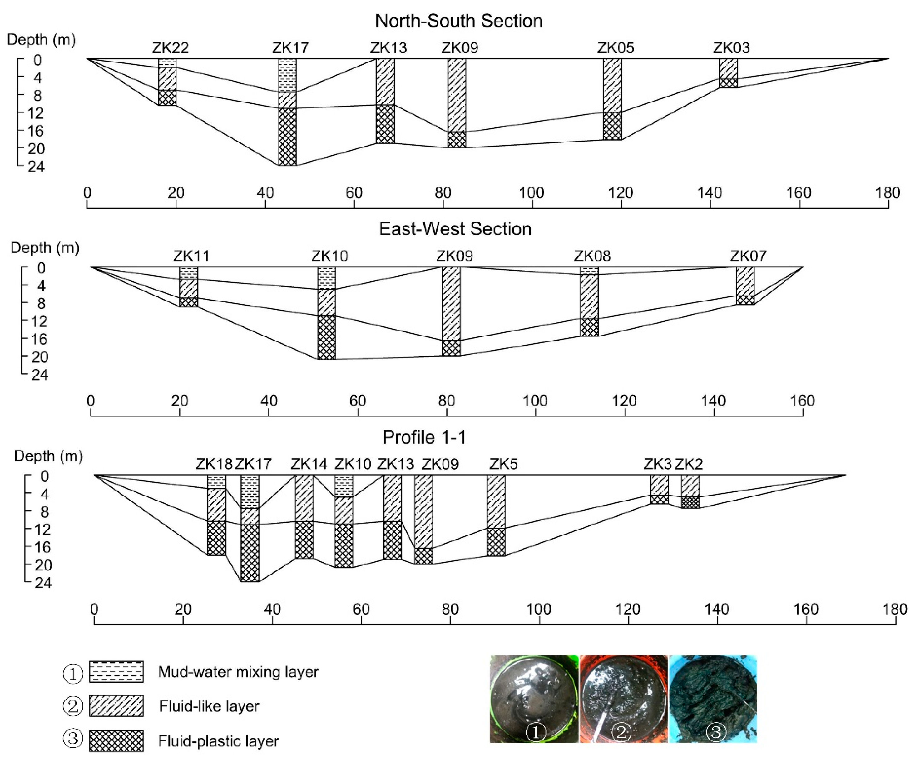
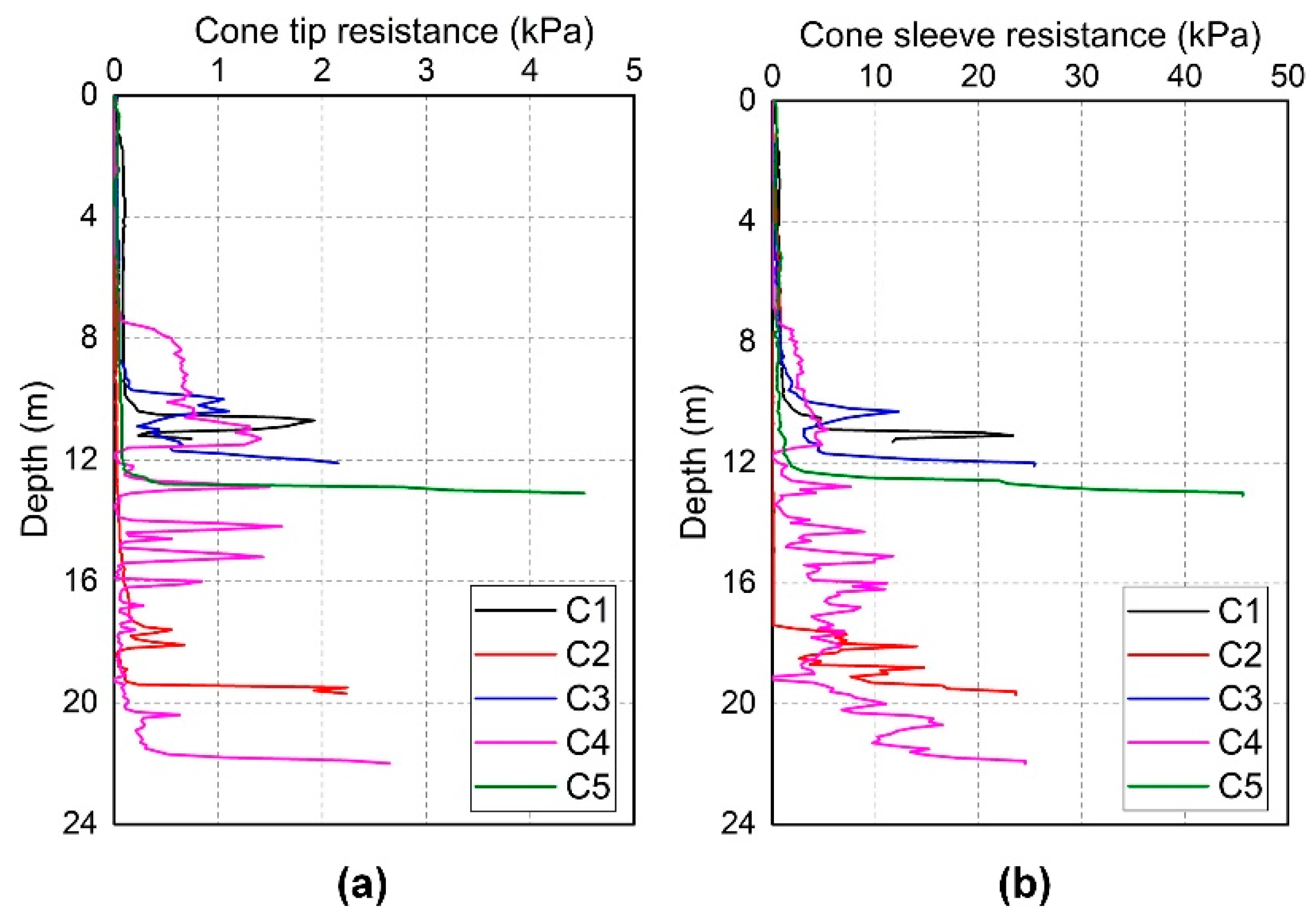
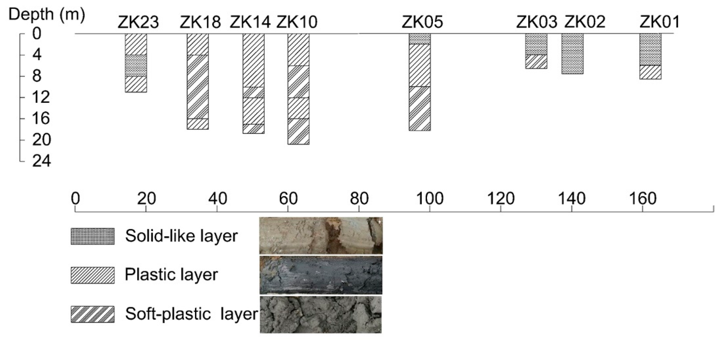
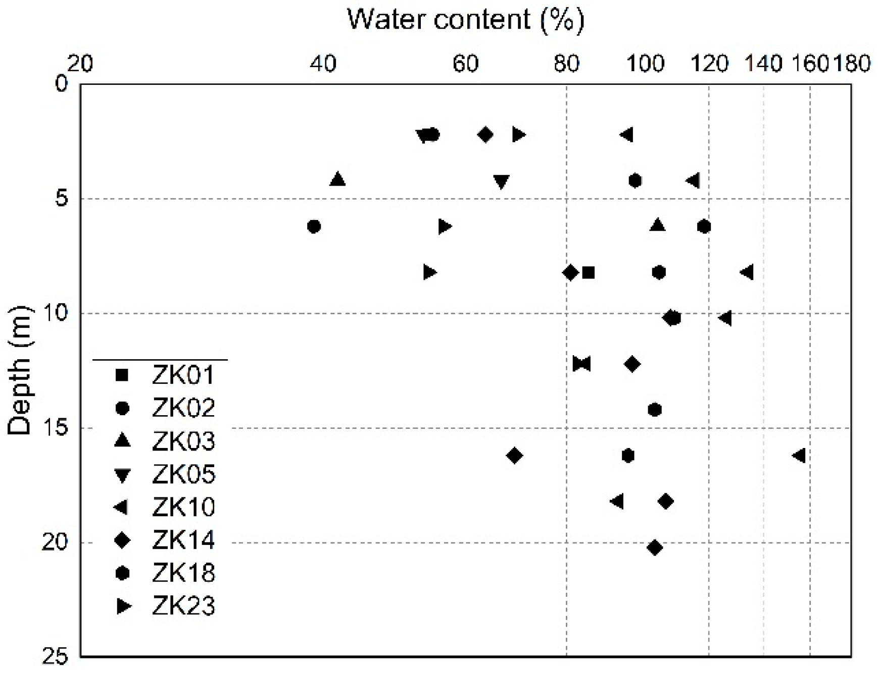
The raw storage sludge in the sludge pond at the Qizishan landfill is stratified into layers, which are mud–water mixing sludge, fluid sludge, and fluid–plastic sludge layers. As the buried depth increases, the water content of the sludge decreases and the undrained shear strength increases. The water content ranges from 172% to 7270%, with an average of about 1397%, and the strength remains at a low level overall, which ranges from 0.20 kPa to 14.90 kPa.
(2)
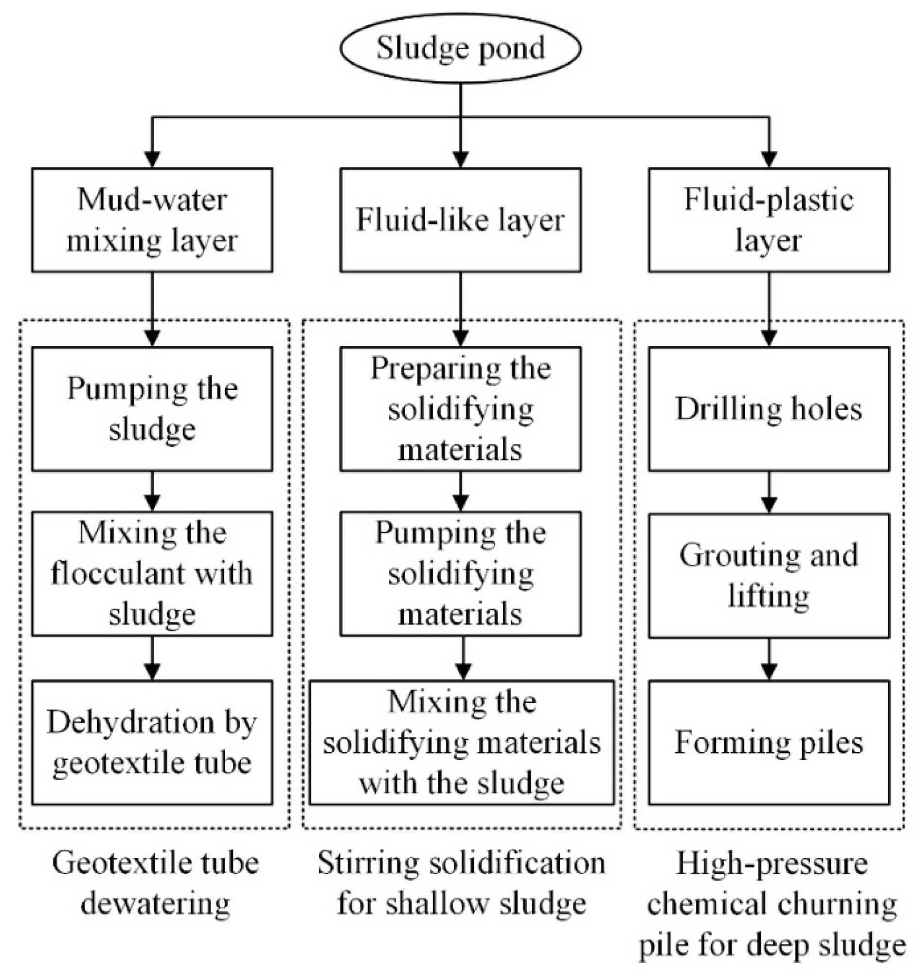
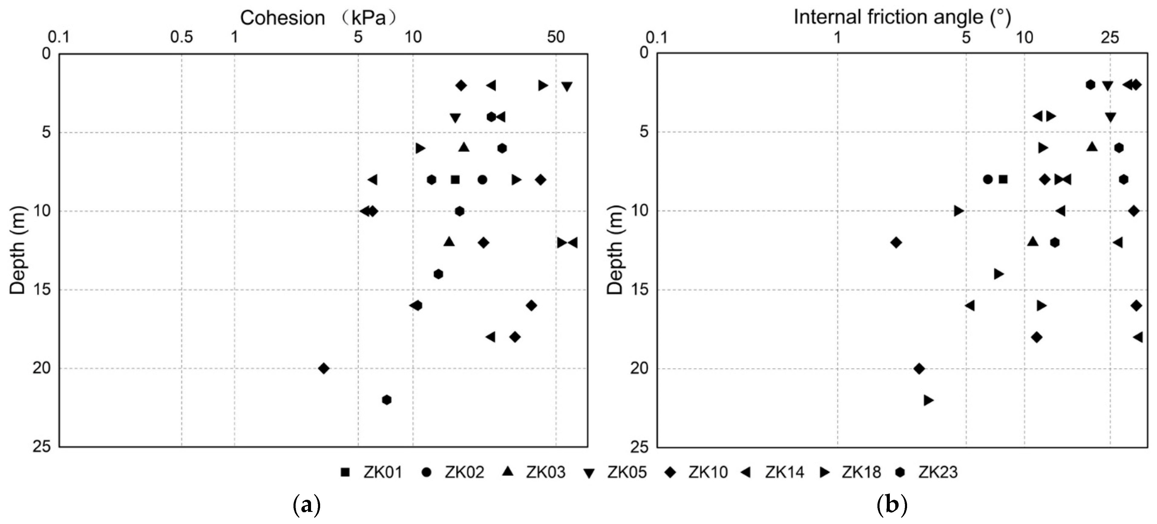
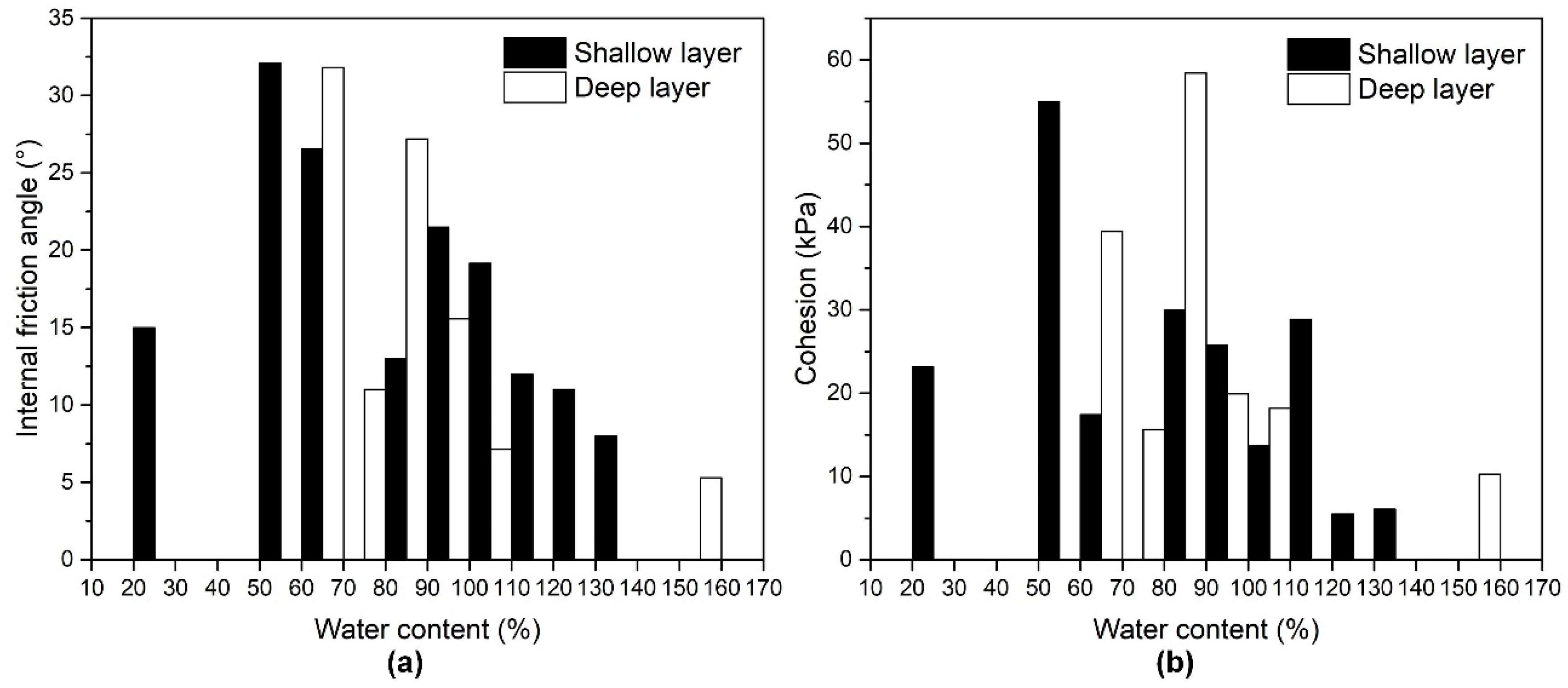
The ex situ dehydration of the mud–water mixing sludge uses the geotextile tubes, in which the flocculation is conducted, and is followed by the high-pressure dehydration. The fluid and fluid–plastic sludges are solidified through in situ stirring and high-pressure churning, respectively. The stratified treatment results in a significant decrease from 1398% to 88% in the average water content and an increase to 23.52 kPa, on average, in the cohesion.
(3)
The strength of the deep solidified sludge varies more dramatically with the water content than that of the shallow solidified sludge. The high content of clay particles, low amount of solidification products, and high water content together result in the strength of the deep solidified sludge having a higher sensitivity to the water content than that of the shallow solidified sludge.
(4)
The landfill body is prone to sliding along the inside of the sludge pond when the waste is piled directly above the raw sludge pond. The stability analysis of the waste body on the solidified sludge pond shows that the potential sliding surface occurs in the fresh waste body rather than in the solidified sludge pond, and the Fs is increased from 0.934 to 1.464, which verifies the validity of the presented sludge pond treatment.

Author Contributions

Conceptualization, K.A.; Funding acquisition, Y.C.; Project administration, Y.C.; Supervision, L.Z.; Writing—original draft, K.A.; Writing—review & editing, W.L., D.Z. and A.A. All authors have read and agreed to the published version of the manuscript.

Funding

This work was supported by the Basic Science Center Program for Multiphase Media Evolution in Hypergravity of the National Natural Science Foundation of China (No. 51988101), the Fundamental Research Funds for the Central Universities (No. 2020QNA4020), and the National Natural Science Foundation of China (Grant no. 51478426).

Conflicts of Interest

The authors declare no conflict of interest.

References

  1. Demirbas, A.; Edris, G.; Alalayah, W.M. Sludge production from municipal wastewater treatment in sewage treatment plant. Energy Sources Part A Recover. Util. Environ. Eff. 2017, 39, 999–1006. [Google Scholar] [CrossRef]
  2. Liu, T.; He, J.; Cui, C.; Tang, J.; Wang, M. Effect of woody and non-woody bulking agents on biodrying of long-term storage sludge. Desalination Water Treat. 2018, 129, 53–61. [Google Scholar] [CrossRef] [Green Version]
  3. Zhan, T.L.; Zhan, X.; Lin, W.; Luo, X.; Chen, Y. Field and laboratory investigation on geotechnical properties of sewage sludge disposed in a pit at Changan landfill, Chengdu, China. Eng. Geol. 2014, 170, 24–32. [Google Scholar] [CrossRef]
  4. Fytili, D.; Zabaniotou, A. Utilization of sewage sludge in EU application of old and new methods—A review. Renew. Sustain. Energy Rev. 2008, 12, 116–140. [Google Scholar] [CrossRef]
  5. O’Kelly, B.C. Geotechnics of municipal sludges and residues for landfilling. Geotech. Res. 2016, 3, 148–179. [Google Scholar] [CrossRef] [Green Version]
  6. Zhao, L.; Gu, W.-M.; He, P.-J.; Shao, L.-M. Effect of air-flow rate and turning frequency on bio-drying of dewatered sludge. Water Res. 2010, 44, 6144–6152. [Google Scholar] [CrossRef] [PubMed]
  7. Lin, W.A.; Zhan, X.J.; Zhan, L.T.; Chen, Y.M.; Jin, Y.W.; Jiang, J.N. Effect of FeCl3- conditioning on consolidation property of sew-age sludge and vacuum preloading test with integrated PVDs at the Changan landfill, China. Geotext. Geomembr. 2014, 42, 181–190. [Google Scholar] [CrossRef]
  8. Koda, E.; Szymanski, A.; Wolski, W. Field and laboratory experience with the use of strip drains in organic soils. Can. Geotech. J. 1993, 30, 308–318. [Google Scholar] [CrossRef]
  9. Zhan, X.J. Study on consolidation mechanism of sewage sludge under combined effect of chemical conditioning and vac-uum preloading and its application. Ph.D. Thesis, Zhejiang University, Hangzhou, China, 2016. (In Chinese). [Google Scholar]
  10. Chu, J.; Goi, M.H.; Lim, T.T. Consolidation of cement-treated sewage sludge using vertical drains. Can. Geotech. J. 2005, 42, 528–540. [Google Scholar] [CrossRef]
  11. Guezennec, A.G.; Michel, C.; Bru, K.; Touze, S.; Desroche, N.; Mnif, I.; Motelica-Heino, M. Transfer and degradation of poly-acrylamide-based flocculants in hydrosystems: A review. Environ. Sci. Pollut. Res. 2015, 22, 6390–6406. [Google Scholar] [CrossRef] [Green Version]
  12. Wu, Y.; Lin, Z.; Kong, G.; Hu, T. Treatment of municipal sludge by Fenton oxidation combined vacuum preloading. Environ. Sci. Pollut. Res. 2018, 25, 15990–15997. [Google Scholar] [CrossRef] [PubMed]
  13. Wang, Y.; Zhou, Y.; Feng, D.; Wu, C.; Wang, X.; Min, F. Effects of Chemical Conditioners on Deep Dewatering of Urban Dewatered Sewage Sludge in the Temporary Sludge Lagoon. J. Environ. Eng. 2019, 145, 04019063. [Google Scholar] [CrossRef]
  14. Benoit, J.; Eighmy, T.T.; Crannell, B.S. Landfilling Ash/Sludge Mixtures. J. Geotech. Geoenvironmental Eng. 1999, 125, 877–888. [Google Scholar] [CrossRef]
  15. Lim, T.; Chu, J.; Goi, M. Effects of cement on redistribution of trace metals and dissolution of organics in sewage sludge and its inorganic waste-amended products. Waste Manag. 2006, 26, 1294–1304. [Google Scholar] [CrossRef] [PubMed]
  16. Disfani, M.M.; Arulrajah, A.; Maghoolpilehrood, F.; Bo, M.W.; Narsilio, G.A. Geotechnical characteristics of stabilised aged bio-solids. Environ. Geotech. 2015, 2, 269–279. [Google Scholar] [CrossRef]
  17. Kayser, C.; Larkin, T.; Singhal, N. Amendment of biosolids with waste materials and lime: Effect on geoenvironmental properties and leachate production. Waste Manag. 2015, 46, 165–175. [Google Scholar] [CrossRef] [PubMed]
  18. Xin, D.; Chai, X.; Zhao, W. Hybrid cement-assisted dewatering, solidification and stabilization of sewage sludge with high organic content. J. Mater. Cycles Waste Manag. 2014, 18, 356–365. [Google Scholar] [CrossRef]
  19. Legiec, I.A.; Jensen, R.H.; Little, N.K.; Bryan, R.E.; McDevitt, M.F.; Campbell, B.D. In situ solidification of an industrial sludge la-goon: Laboratory studies and field activities. Journal of Environmental Science and Health. Part A Environ. Sci. Eng. Toxicol. 1996, 31, 2777–2799. [Google Scholar]
  20. Zhan, L.T.; Luo, X.Y.; Guan, R.Q.; Zen, X.; Lan, J.W.; Chen, Y.M.; Lin, W.A. Failure mechanism of sludge pit and downstream waste slope of a MSW landfill. Chin. J. Geotech. Eng. 2013, 35, 1189–1196. (In Chinese) [Google Scholar]
  21. Lo, I.M.; Zhou, W.W.; Lee, K.M. Geotechnical characterization of dewatered sewage sludge for landfill disposal. Can. Geotech. J. 2002, 39, 1139–1149. [Google Scholar] [CrossRef]
  22. Cao, Y.H.; Yin, C.Q. Engineering Properties and Landfill of Stabilized Sludge. In Proceedings of the International Conference on Sustainable Energy and Environmental Engineering (ICSEEE 2012), Guangzhou, China, 29–30 December 2012; 29–30; Volume 295–298, pp. 1751–1754. [Google Scholar]
  23. ASTM D2974-20 Standard Test Methods for Determining the Water (Moisture) Content, Ash Content, and Organic Ma-terial of Peat and Other Organic Soils; ASTM International: West Conshohocken, PA, USA, 2020; 5p.
  24. ASTM D3441–16 Standard Test Method for Mechanical Cone Penetration Testing of Soils; ASTM International: West Conshohocken, PA, USA, 2016; 8p.
  25. ASTM D2573/D2573M−18 Standard Test Method for Field Vane Shear Test in Saturated Fine-Grained Soils; ASTM International: West Conshohocken, PA, USA, 2018; 8p.
  26. Pavlović, M.N.; Cotsovos, D.M.; Dedić, M.M.; Savidu, A. Reinforced jet-grouted piles. Part 1: Analysis and design. Proc. Inst. Civ. Eng. -Struct. Build. 2010, 163, 299–308. [Google Scholar] [CrossRef]
  27. Zouboulis, A.I.; Tzoupanos, N.D. Polyaluminium silicate chloride-A systematic study for the preparation and applica-tion of an efficient coagulant for water or wastewater treatment. J. Hazard. Mater. 2009, 162, 1379–1389. [Google Scholar] [CrossRef] [PubMed]
  28. Bharti, S.; Mishra, S.; Sen, G. Ceric ion initiated synthesis of polyacrylamide grafted oatmeal: Its application as flocculant for wastewater treatment. Carbohydr. Polym. 2013, 93, 528–536. [Google Scholar] [CrossRef]
  29. Muthukumaran, A.E.; Ilamparuthi, K. Laboratory studies on geotextile filters as used in geotextile tube dewatering. Geotext. Geomembr. 2006, 24, 210–219. [Google Scholar] [CrossRef]
  30. AASHTO T236-08 Standard Method of Test for Direct Shear Test of Soils under Consolidated Drained Conditions; AASHTO: Washington, DC, USA, 2018; 9p.
  31. Hu, Z.F.; Fu, Y.R. Experimental Study of the Shear Strength of Soft Soil with Different Initial Water Content. Shanghai Geol. 2000, 77, 38–42. [Google Scholar]
  32. Ma, P.C.; Ke, H.; Lan, J.W.; Chen, Y.M.; He, H.J. Field measurement of pore pressures and liquid-gas distribution using drilling and ERT in a high food waste content MSW landfill in Guangzhou, China. Eng. Geol. 2019, 250, 21–33. [Google Scholar] [CrossRef]
  33. CJJ 176-2012. Technical Code for Geotechnical Engineering of Municipal Solid Waste Sanitary Landfill; China Building Industry Press: Beijing, China, 2012. (In Chinese) [Google Scholar]
Figure 1. (a) Location and (b) layout of the Qizishan landfill.
Applsci 11 12102 g001
Figure 2. Borehole layout and the water content zoning in the sludge pond at the Qizishan landfill.
Applsci 11 12102 g002
Figure 3. The three layers of the raw sludge in the sludge pond.
Applsci 11 12102 g003
Figure 4. Water content of raw sludge, varying with the depth.
Applsci 11 12102 g004
Figure 5. Cone penetration test results of the raw sludge, varying with depth: (a) cone tip resistance and (b) cone sleeve resistance.
Applsci 11 12102 g005
Figure 6. Undrained shear strength of the raw sludge varying with the depth.
Applsci 11 12102 g006
Figure 7. Schematic description of the stratified treatment of the sludge pond.
Applsci 11 12102 g007
Figure 8. The complete technique drawings of sludge pond treatment: (a) dehydration of the geotextile tube, (b) in situ stirring solidification equipment, (c) high-pressure chemical churning pile, and (d) composite liner above the solidified sludge pond.
Applsci 11 12102 g008
Figure 9. Photos of the sludge pond at the Qizishan landfill: (a) laying the composite liner after solidification, and (b) waste landfilling above the solidified sludge pond.
Applsci 11 12102 g009
Figure 10. Profile 1-1 of the solidified sludge taken from the boreholes.
Applsci 11 12102 g010
Figure 11. Water content of the solidified sludge, varying with the depth.
Applsci 11 12102 g011
Figure 12. The shear strength parameters of the samples taken from the boreholes: (a) the cohesion of the solidified sludge varying with the depth and (b) the internal friction angle of the solidified sludge varying with the depth.
Applsci 11 12102 g012
Figure 13. The mean shear strength parameters within each range of water content among the solidified sludge in the shallow layer and deep layer: (a) the mean cohesion of the solidified sludge varying with the water content and (b) the mean internal friction angle of the solidified sludge varying with the water content.
Applsci 11 12102 g013
Figure 14. Critical failure surface for downstream waste slope filling with 40-m thick waste above the sludge pond: (a) landfilling waste on the raw sludge pond and (b) using the non-uniform solidified sludge as a part of the waste foundation.
Applsci 11 12102 g014
Table 1. Components of the solidifying agent.
ComponentsPortland CementFly AshQuick LimeFerrous SulfateAluminum SulfateCalcium Chloride
Weight percentage (%)33.215.423.718.17.22.4
Table 2. Shear strength parameters used for the stability analysis.
MaterialUnit Weight
(kN/m3)
Cohesion
(kPa)
Internal Friction Angle (°)
Shallow waste11.720.821.4
Old waste1229.50
Fresh waste1021.69.6
Waste dam2020050
Mud-water mixing sludge1000
Fluid sludge10.0240
Fluid-plastic sludge10.08100
Composite liner18020
Publisher’s Note: MDPI stays neutral with regard to jurisdictional claims in published maps and institutional affiliations.

