Article

An Approach Based on VR to Design Industrial Human-Robot Collaborative Workstations

by
Elisa Prati
1,†,
Valeria Villani
2,†,
Margherita Peruzzini
1,* and
Lorenzo Sabattini
2
1
Department of Engineering “Enzo Ferrari” (DIEF), University of Modena and Reggio Emilia, 41124 Modena, Italy
2
Department of Sciences and Methods for Engineering (DISMI), University of Modena and Reggio Emilia, 42121 Reggio Emilia, Italy
*
Author to whom correspondence should be addressed.
These authors contributed equally to this work.
Appl. Sci. 2021, 11(24), 11773; https://doi.org/10.3390/app112411773
Submission received: 27 October 2021 / Revised: 25 November 2021 / Accepted: 6 December 2021 / Published: 11 December 2021
(This article belongs to the Special Issue Focus on Integrated Collaborative Systems for Smart Factory)

Abstract

:
This paper presents an integrated approach for the design of human-robot collaborative workstations in industrial shop floors. In particular, the paper presents how to use virtual reality (VR) technologies to support designers in the creation of interactive workstation prototypes and in early validation of design outcomes. VR allows designers to consider and evaluate in advance the overall user experience, adopting a user-centered perspective. The proposed approach relies on two levels: the first allows designers to have an automatic generation and organization of the workstation physical layout in VR, starting from a conceptual description of its functionalities and required tools; the second aims at supporting designers during the design of Human-Machine Interfaces (HMIs) by interaction mapping, HMI prototyping and testing in VR. The proposed approach has been applied on two realistic industrial case studies related to the design of an intensive warehouse and a collaborative assembly workstation for automotive industry, respectively. The two case studies demonstrate how the approach is suited for early prototyping of complex environments and human-machine interactions by taking into account the user experience from the early phases of design.

1. Introduction

In modern factories, humans and robots frequently coexist in a common space, where robots complement the operator’s capabilities, while humans take care of the most delicate tasks (e.g., high precision tasks, visual quality check, decision-making, strategic process control) [1]. human-robot interaction (HRI) refers to all those processes where humans and robots work together, sharing the same space, time, and resources [2]. More specifically, human-robot collaboration (HRC) takes place in a specific collaborative shop floor, where robots and humans can perform tasks concurrently, also having direct, physical contact with each other [3]. Multiple workstations where machines and humans collaborate with each other are frequently created in order to accelerate industrial processes, by benefiting from both robotic and human work. This practice is becoming pretty common in highly automated assembly processes.
In this context, shared human-robot activities should be carefully designed to properly execute collaborative tasks in the most efficient and effective way, considering not only system productivity, but also the physical and cognitive workload of the human operator, and exploring the effects of collaboration on system usability and worker’s perceived cognitive workload and visual attention [4]. Moreover, it is noteworthy that in this scenario operators’ responsibilities and workload further increase due to high production rates, complex task demand, time pressure, as well as monitoring and control jobs [5]. As a consequence, the new human-robot collaborative work can bring to stressful working conditions for human operators, causing physical stress and cognitive tensions [6].
Nevertheless, as a major advantage, the availability of human-robot collaborative solutions allows to combine the advantages of robots, such as high accuracy, speed, and repeatability, with the flexibility and cognitive skills of human workers. As a result, such solutions have become important tools to face growing needs of flexible production and rapidly changing market demands. Such phenomena, framed in the concept of Industry 4.0, affect any size organizations. On the one side, small and medium-sized enterprises (SMEs) are directly affected, since one of their strengths is that they can accommodate specific market requests allowing for high product customization, small batches production and one-piece flow. SMEs benefit from their intrinsic agility and limited inertia in decision and operational processes to accommodate dynamically changing market requests. This represents a market niche where SMEs still hold a significant competitive advantage over bigger companies and, as such, it should be protected and enhanced. Nevertheless, SMEs often do not have a solid management infrastructure to help accommodating flexible production in an ordered manner [7]. On the other side, as regards bigger companies, the automation trend introduced by Industry 4.0 is to achieve high flexibility also for them: this requirement is partially conflicting with their bulky organization and layered structure. Thus, to achieve the goal of flexibility, while preserving the capability to accommodate constantly changing market requests, proper technological solutions are needed to reorganize workstations as promptly as possible at the beginning of new production cycles [8].
A good solution in this regard is represented by digital tools, offering effective visualization and simulation of such collaborative processes, before their realization [9]. Moreover, recent advances in Information and Communication Technology (ICT) have brought to an increased maturity of also X-Reality (XR) technologies, such as Virtual Reality (VR) and Augmented Reality (AR), showing promising opportunities for researchers and industries to simulate new types of HRI and HRC [10]. In particular, VR provides an immersive, fully digital environment where objects are modeled by computer graphics and users can interact with the virtual world in a realistic way, with autonomous control and multi-sensory feedback, making users observe, explore and experience virtual spaces perceived as real worlds. In collaborative robotics, VR technologies can be validly used to study and prototype workstation concepts and design the most suitable interfaces, evaluating their validity with much lower expenses than in real environment and in a environment safe for users [11]. The use of VR has the potential to simulate cooperative processes in advance, considering HRI from the design stages, and to include workers and their individual behavior into the simulation. Thanks to these benefits, there has been a significant increase in the use of VR in robotics in last years [12]. Moreover, VR simulations allow securing collaborative processes and reducing physical and mental barriers between humans and robots.
Main examples of the implementation of VR solutions in HRC contexts refer to the simulation of future working environment, before its realization, in order to validate the envisaged solutions against initial requirements [13] or the support to design cooperative tasks, from movements definitions to task distribution [14,15,16]. The main areas of application of VR for industrial HRC range from collaborative assembly [10,17], to welding [16], to robot control [18], to manipulation and training [10]. However, only a few studies focused on the user-centred perspective and the use of VR to simulate not only the workspace, but also interactions between the human worker and the robot [19]. In this context, there is a lack of methodologies to link VR technologies and HRI applications considering human requirements. For these purposes, new approaches are required to create virtual simulations able to predict and visualize HRI and support the design of proper interfaces. The availability of such approaches would enable a fruitful collaboration and partnership between humans and machines.

1.1. Contributes from Literature

To stay competitive, manufacturing companies need to react quickly and flexibly to market demands. A necessary feature to meet varying needs of customers is versatility towards changes or modifications. For this purpose, companies need a method to effectively achieve a faithful digital and interactive replica of the workstation. It will support to predict space occupancy and reachability, thus identifying the optimal physical layout of the workcell, as well as address safety and ergonomics issues. On the other side, such a replica may help early definition and testing of the most suitable interaction tools, in particular human-machine interfaces (HMIs), also defining the best modalities of interaction.
VR is a promising tool to address all these aspects and provide effective early prototyping of collaborative workstations. Several works in the literature have proposed VR-based approaches in this regard. Nevertheless, to the best of the authors’ knowledge, an integrated approach to early prototyping of collaborative workstations considering jointly all the aspects relevant for design is lacking. Rather, as summarized in Table 1, previous works have widely investigated the use of VR to address them separately. In particular, one of the most investigated issue refers to the assessment of compliance to ergonomics requirements in early phases of design. Authors in [20] proposed the use of VR and motion capture systems to design human-centered workstations with specific focus on ergonomics requirements. Similarly, VR-based early design of assembly workstations was proposed in [21] considering biomechanical effort and ergonomics. In [22] a human-centred virtual simulation environment to optimize physical ergonomics in workstation design was presented as well. The proposed approach consisted in the creation of a virtual environment for easy testing of different design solutions to optimize physical, cognitive, and organizational ergonomics. As regards the organization of physical layout, the work in [23] considered the use of VR tools with respect to the adjustments of the devices or machines to be used by the operator and the organization of the workplace. The authors in [24] introduced a VR-based approach that allows the simultaneous visualization, investigation, and analysis for factory planning, hence considering material flows, resource utilization and logistics at all levels of a factory. Moreover, VR has been used in this context to provide training and support of operators in new workstations or new tasks: examples were provided by [25,26]. VR has been also used for product or process design and a detailed review was provided in [27]. On the contrary, the use of VR in HMI design has been scarcely investigated. In [28] the authors presented the use of VR to develop high fidelity HMI prototypes to engage more successfully users in a participatory HMI design process. This study also showed that VR is a valid alternative to traditional methods for evaluating HMI usability, allowing designers to test the HMI safely and in advance. HMI design testing is probably the most exploited topic so far: several studies proposed the use of VR for the interaction testing phase, particularly in autonomous vehicles and aviation fields. For example, VR was used to test the user experience [29], the user’s level of trust [30], and consequently readjust the interface concept [31]. The existing literature has demonstrated how the use of VR can validly support the design and evaluation of HMIs for complex systems, and suggested how VR can benefit HMI design also in the industrial context.

1.2. The Proposed Contribution

In this paper, we present an integrated technical approach to design complex industrial workstations or shop floors, where human operators, robots, and machines share space, interact, and collaborate. The approach describes how to practically use VR simulations to create early rapid prototypes of the operation environment, where the interactions among all the involved agents can be simulated in a realistic way. As a result, different solutions for the organization of the environment can be tested and validated, in terms of positioning of tools, space occupancy, human visibility, and accessibility, as well as the analysis of tasks and environment according to the user’s and interaction requirements. Thus, for example, the design and location of interaction devices (e.g., interfaces, supporting tools) can be decided on the basis of real processes and not only of their nominal execution. The optimal solution, considering the operative context and its constraints, can be then identified. Such an approach allows to concurrently take into account the different key aspects in the design of industrial workstations, from physical layout to space organization, physical and cognitive ergonomics, to the quality of interaction with other agents.
To achieve this goal, the proposed approach is organized in two layers, deeply interconnected. The first layer consists in the virtual design of the environment where interaction and collaboration take place; the second layer is built upon the former and adds the human-machine interaction requirements, thus focusing on the interface design, prototyping and testing. The second layer also offers a validation space to promote collaboration between humans and automatic agents. The workflow to create the two above-mentioned layers is summarized in Figure 1 and described in details in Section 2. To implement such layers, we exploit existing software tools and platforms and propose their combined use to provide a novel approach for the early design and prototyping of collaborative workstations.

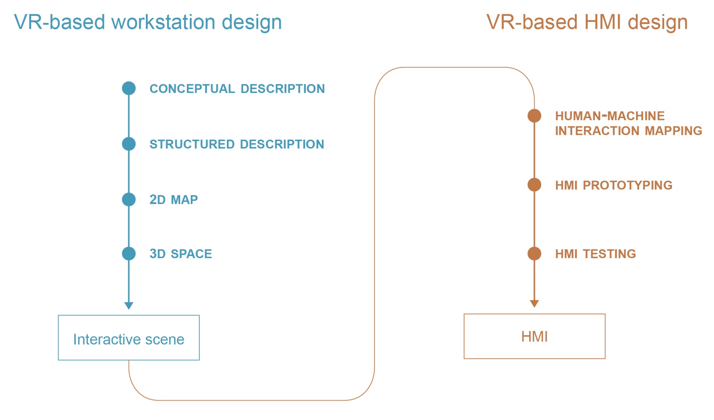
2. The Proposed Approach

The presented approach proposes the use of VR during the design of new human-robot collaborative workstations. This aims at allowing designers to immerse themselves in the scenario before its realization. The ultimate goal is to facilitate the analysis, the design and the testing phases adopting a user-centered approach.
This goal is achieved by resorting to a two level VR-based approach, as shown in Figure 1: rapid prototyping of the workstation layout and HMI design. The first one is described in Section 2.1 and consists of three phases (Creation of a structured description of the scene, Creation of a 2D map of the workstation, Creation of a 3D environment of the workstation) that lead to the creation of an interactive workstation prototype in VR. The latter represents the starting point of the second step of the approach, which guides the HMI design in 3 steps (Human-machine interaction mapping, HMI prototyping, HMI testing), as presented in Section 2.2.

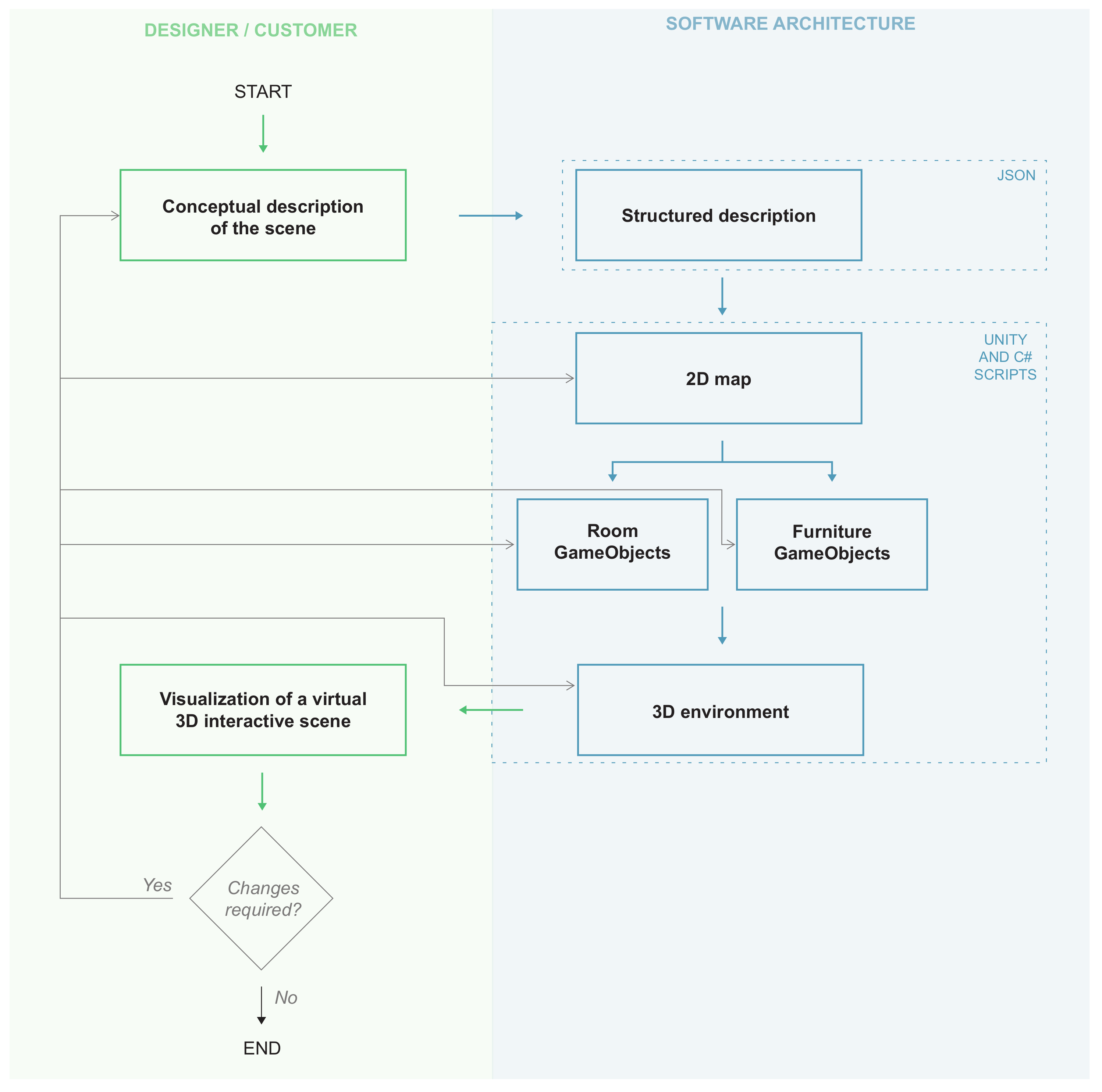
2.1. VR-Based Rapid Prototyping of the Workstation Layout

As a first module of the proposed approach, we consider the use of VR to create a fast prototype of the workstation physical layout. Specifically, we aim to automatically generate a virtual working environment starting from its unstructured description, such as a text or a graphical sketch. This allows the creation of a prototype from the earliest phases of design and the quick visualization of any change. To achieve this goal, as a first step, the initial unstructured description has to be converted in a labeled textual description that contains the most relevant information of the scene to create. Starting from this, a bi-dimensional (2D) map on the environment is created, containing all the desired elements. Finally, a three-dimensional (3D) rendering of the scene is created. The process is depicted in Figure 2 and is detailed in the following sections. In the figure, grey denotes actions that can (or should) be taken directly by the designer (or their customer), such as the definition of the desired scene, while blue denotes the actions that are in charge to the proposed software architecture. It is worthwhile noting that the availability of the proposed early prototyping method implies the possibility of multiple iterations on the design of the desired scene. Grey arrows in the figure denote that changes requested during such iterations can be easily applied by the designer (or their customer) directly at a software level for rapid testing.

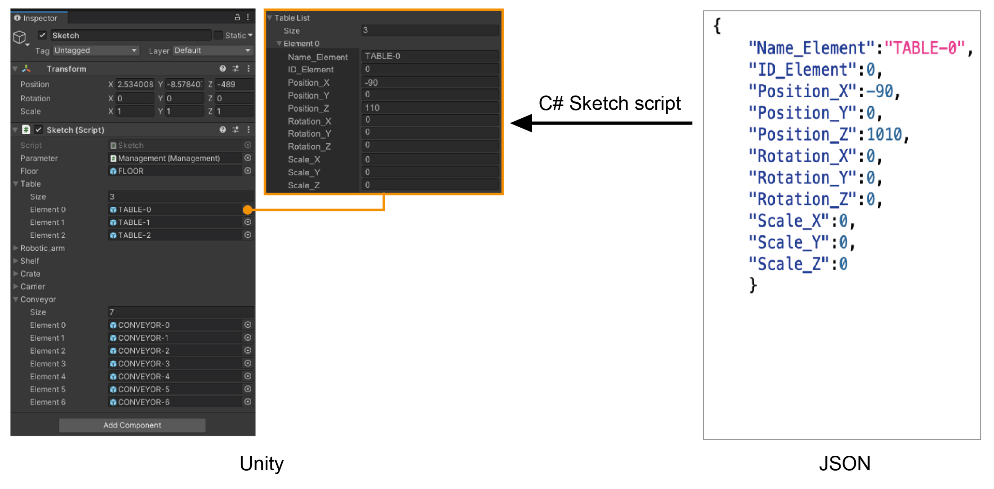
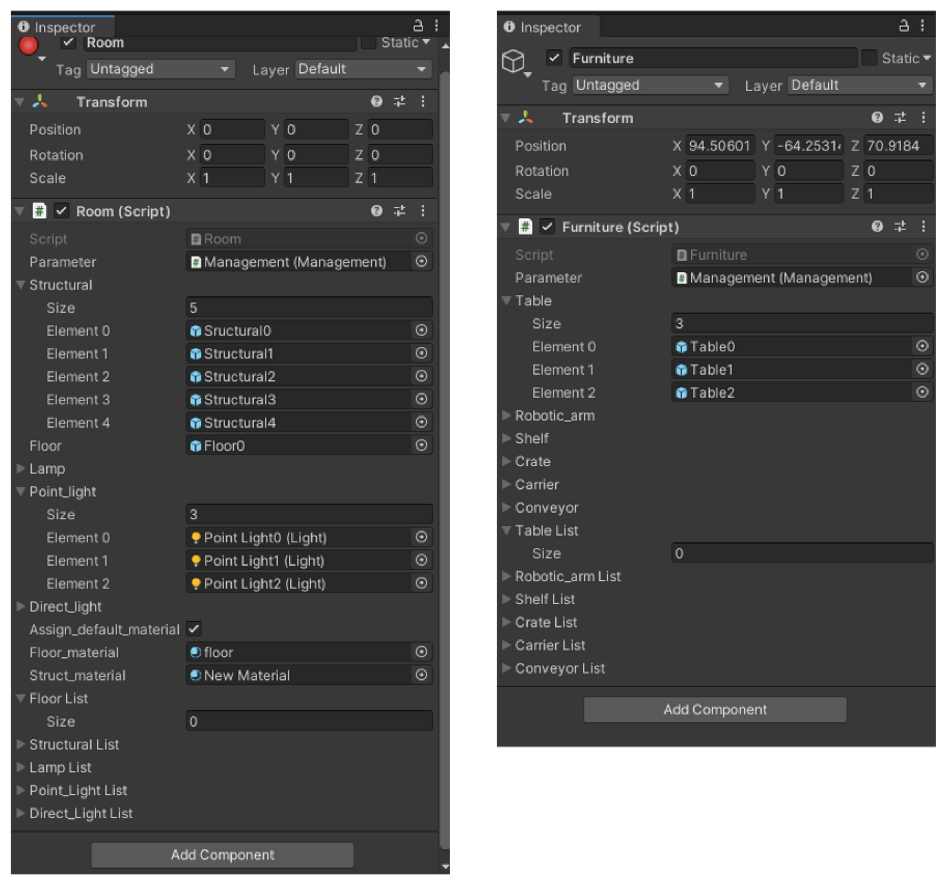
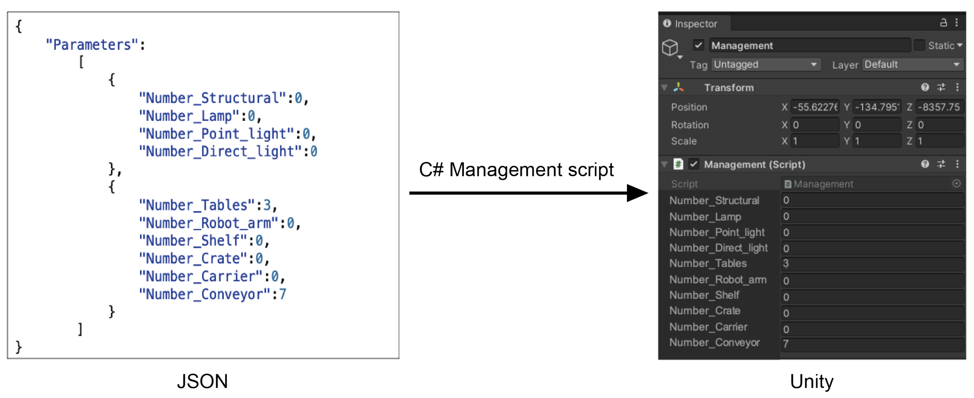
2.1.1. Creation of a Structured Description of the Scene

We assume that the starting point to the proposed approach is an unstructured and unlabeled description of the workstation to prototype. As such, the first step consists in the extraction of a structured description of the scene so that it can be automatically processed by the proposed system. Such a description contains the elements required in the scene, their position and size. As elements, we refer to architectural items, such as floor, walls or lamps, furniture, which, for example, may include tables, shelves, and any other working tools that may be needed, such as robots or conveyors. In principle, any element can be added to build the desired work environment, provided that its 3D CAD model is available. Moreover, any situational factor that can be relevant in a reliable replica of the environment revshould be considered. This is the case, for example, of specific environmental conditions, such as noise or dust, or the presence of human operators, which might be useful to assess space occupancy or specific interaction dynamics (as explained in Section 2.2.1, we refers to where interactions happen, which they are, what are their direction and when they happen).
Table 2 reports a reference list of possible elements to include in the scene. This list has been derived following an analysis of the most recurrent categories of elements in shopfloors and workstations. Nevertheless, it can be extended depending on specific applications.
To organize such information (elements and their features), it is necessary to define a structured format, which can subsequently be processed by the system in a (semi)automated manner. For this purpose, several standard formats exist: among the most popular ones, we considered the use of JavaScript Object Notation (JSON, https://www.json.org/json-en.html, accessed on 24 June 2021) and Extensible Markup Language (XML, https://www.w3schools.com/xml/xml_whatis.asp, accessed on 24 June 2021) data-interchange formats. JSON is an open standard file format based on key-value pairs and ordered lists; XML organizes data with a start-tag, its content and an end-tag. Following a comparison between these two formats, JSON has been selected as the most suited for the proposed approach, since it is characterized by low verbosity and concise syntax. Indeed, these features are of particular importance with reference to early and fast prototyping and rapid visualization of changes.
As a result, the output of this step is a labeled text, structured according to the JSON format, where, for each element in Table 2, the following information is reported: number of items per element to add and, for each item, position, rotation and scale factor with respect to the original size in the reference CAD model.

2.1.2. Creation of a 2D Map of the Workstation

Starting from the labeled description of the scene and related elements, a 2D map of the environment is then created. This represents an intermediate step before the creation of the realistic 3D map. Specifically, the 2D map is used to locate the requested elements in the environment, thus creating a sort of placeholders. Figure 3 shows an example of a 2D map as output of the second step of the proposed approach. Different colors are used to identify different classes of elements.
To generate the 2D map, a software platform needs to be defined that is able to process the structured description. For this purpose, we considered the Unity game engine (https://unity.com/, accessed on 24 June 2021). Unity has been used together with specific C# scripts that allow automatic processing of JSON description of the scene and creation of the 2D map. In particular, we implemented two different scripts: one, called Management, is used to extract the number of items, for each of the possible elements listed in Table 2, that are required in the environment; the other, denoted in the following as Sketch, extracts the specific features of each item from the JSON description of the environment. Such scripts are integrated in Unity, as shown in Figure 4. The figure shows the Unity interface for an empty environment (only a Main camera and a Directional light are present, since they are intrinsically associated to the existence of a scene in Unity). The “Hierarchy” panel on the left shows the presence of the elements (called GameObjects in Unity) Management and Sketch, which are generated by the corresponding scripts. On the right, the “Inspector” panel shows the details of each GameObject.
To clarify the roles of these scripts and their integration in Unity, we consider the case of a simple environment populated by a floor, three tables and seven conveyors. Figure 5 shows the content of the GameObject Management in Unity and the reference JSON description.
In particular, the GameObject Management reports the number of elements, for each type in Table 2. Then, for each non-zero element in this panel, a vector is automatically created by the Sketch script, which contains the corresponding number of items. Figure 6 shows the result of this process. In particular, with reference to the considered example, a vector of size 3 is created for the GameObject “Table”, whose components are “TABLE-0”, “TABLE-1” and “TABLE-2”, and a vector of size 7 for “Conveyor” (left). The middle panel shows the features (position, rotation and scale factor) of the first table, named “TABLE-0”, which are automatically extracted from the JSON description (right) by the Sketch script.

2.1.3. Creation of a 3D Environment for the Workstation

Once the 2D map has been created, the following step is the creation of a 3D virtual representation of the environment. In general terms, this process consists in linking the 3D CAD models to the placeholders introduced in the 2D map. In order to achieve this objective, we exploited the functionalities of the Unity game engine. In particular, the 3D map is automatically created pressing the Enter button in the “Scene” panel of the Unity interface (Figure 4).
For a more agile creation of the 3D map within the Unity implementation, two further GameObjects are introduced at this level: Room and Furniture. Basically, they group all the possible elements that can be introduced in the scene (see Table 2) in two classes. An example of their content is reported in Figure 7. The need to group possible elements within these two GameObjects is twofold. On the one side, such an organization improves project readability and allows more efficient management of complex environments. On the other side, there exists a major difference between architectural elements and furniture. GameObjects of Room type, such as walls and lamps, are static, while Furniture type elements, such as robots and conveyors, are dynamic and require animations for a dynamic and interactive simulation of the environment. As a result, simulation has to take into account two different reference systems for moving objects: one fixed, considering the position of the element in the environment, and one relative, which takes into account the animation of the object with respect to its position. As a further distinction, Room type GameObjects are quite simple, they are default in Unity and do not have any required hierarchy. On the contrary, Furniture type GameObjects can be customarily added depending on the requirements of the desired workstation and have a nested hierarchy. This is needed not only to introduce the two reference systems, fixed and relative, but also to create animations of subparts of an element (e.g., move the joints of a robot arm) or create aggregated elements, such as mobile manipulators. Examples in this regard are shown in Figure 8: therein, on the left, the 3D models of a robot arm and a mobile manipulator are shown, together with the corresponding hierarchy.
Finally, it is worthwhile noting that to introduce changes to the 3D environment it is not required to change the corresponding JSON description. Indeed, thanks to the use of scripts, the scene can be modified directly through the Unity interface, entering numerical values in the “Inspector” panel or moving and resizing objects with mouse gestures. The advantage brought by this opportunity is that changes can be done in an intuitive manner, without knowledge of the software architecture and JSON format.

2.2. VR-Based Interaction Design

Once the workstation VR prototype has been created, it is possible to proceed with the analysis, design, and testing of interactions occurring in the workplace. To do this, VR allows designers to guide the design process by considering user’s needs during the interactions. In this section, we describe how the VR scenario can be further enhanced to support the interface design process. The proposed approach consists of three phases: (1) human-machine interaction mapping, (2) HMI prototyping, and (3) HMI testing. The proposed steps respect the traditional phases of the HMI design process (analyze, design and prototype, test) and refer to specific techniques for the human-robot interface design [19,32]. The human-machine interaction mapping refers to the analysis phases that guide designers to understand all the interaction aspects in order to choose the more suitable interface for the considered scenario. The HMI prototyping phase guides in the translation of the information identified in the previous phase into low-fidelity and high-fidelity prototypes, within the VR scene. Lastly, the HMI testing phase allows designers to test the interface in the earliest phases of design and anticipate the understanding of its usability and the overall user experience, before building the physical system.
As mentioned, the approach is aimed at designers. During the three phases designers can be both external observers, watching users interacting with the virtual scene, and end user/s, directly experiencing the scenario. Observation is one of the traditional user research techniques, so even in the VR scene the design team could simply assist in carrying out tasks and learn the user’s needs. In this case, the choice of involved users depends on the goals and design phase [33], they could be general users or real end-users. On the other hand, designers carry out the user tasks and interact with the interface prototype. These two roles could also be used in parallel or change according to the design phase. In both cases, the purpose is to understand all the interface features and make sure that it offers a good user experience (UX).
The techniques presented below aim at guiding designers in the analysis, design, and testing of human-robot interactions. The interactions take place through interfaces (e.g., display, gesture, voice), therefore the output of the second layer of the approach is the prototype of the identified interface. Furthermore, this phase could reveal that the interaction modalities provided by the layout, previously developed in step 1, are not optimal or cause inconvenience to the user. In this case it would be necessary to go back to the previous step and change the workstation layout. This cyclical and iterative approach is typical of the user-centered design, in which the user’s needs guide the other design aspects. The use of VR allows to anticipate such iterations before the creation and construction of the physical system in the real environment.

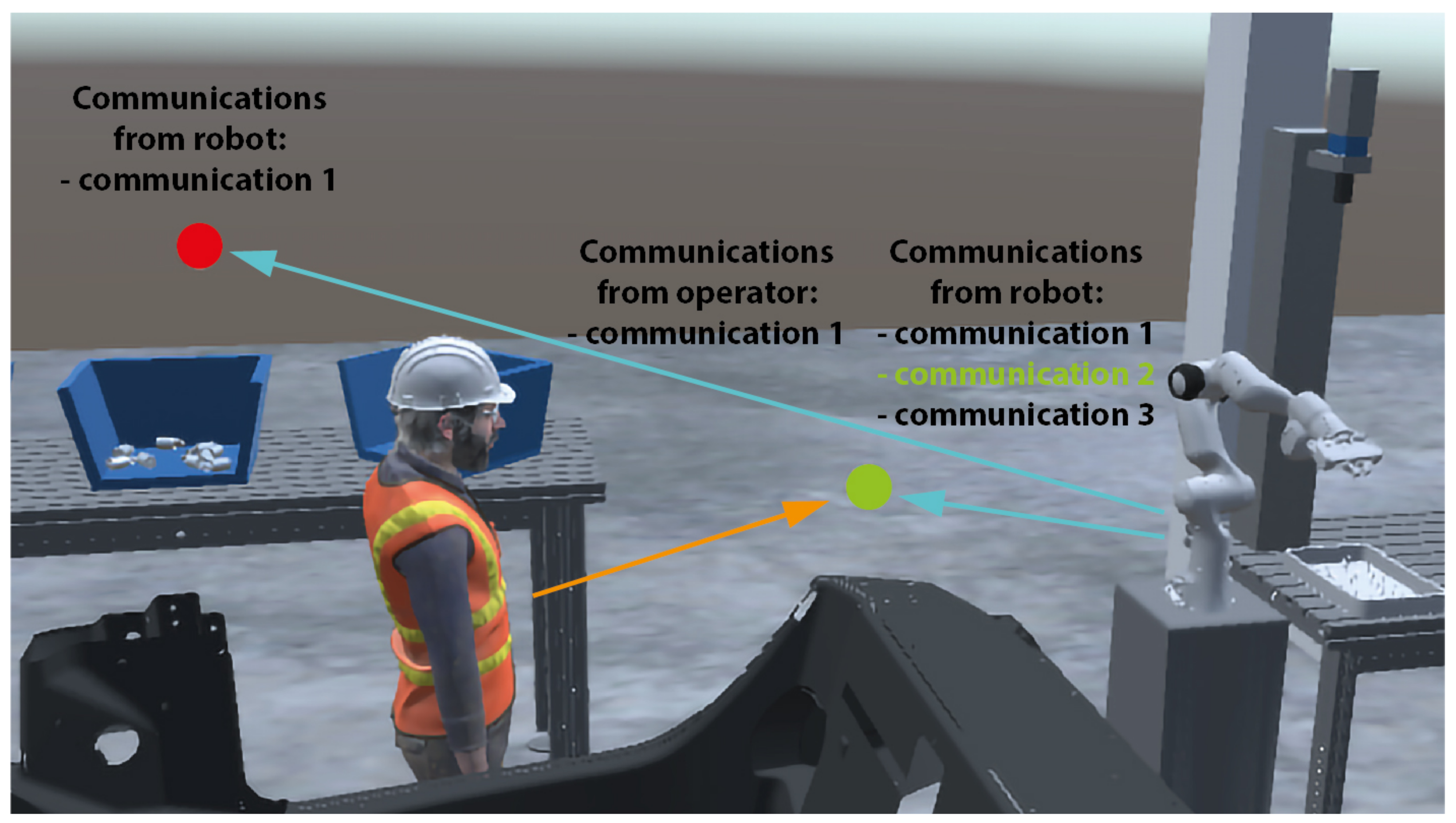
2.2.1. Human-Machine Interaction Mapping

Interaction mapping is the initial stage of the interface design process. In this phase, designers need to consider all the aspects that influence human-machine interactions, such as work conditions and user’s needs. To this end, the VR scenario allows designers taking into consideration all the requirements concurrently. Starting from the virtual scene created according to the described steps in Section 2.1, designers can see all the necessary information at a glance to begin the interaction mapping. In particular, VR helps understanding interactions by showing scene components, actors (e.g., operators, robots) and working conditions (e.g., presence of noise or personal protective equipment worn by the operator/s). The vision of these elements allows designers to understand the following key aspects:
  • where: Where interactions with the interface/s take place;
  • which: Which information must be exchanged through the interface/s;
  • direction: Which communication direction, from/to the user/s and other actors (e.g., robot, system);
  • when: When interactions occur.
These four aspects are essential to define the most suitable interface type (e.g., graphics, voice, gesture) and supporting device according to the specific context of use. Such aspects can be easily mapped and graphically represented in the VR scenario to provide a clear view of the context of use and a deeper understanding of the user experience. To this end, a set of graphic elements have been identified to map the four key aspects (an example is depicted in Figure 9):
  • where: Represented with a balloon where the interactions with the interface will take place;
  • which: Represented with a text label about the information to be exchanged, distinguishing those from user/s to other actors and vice versa;
  • direction: Represented with an arrow pointing to or from the identified interaction point;
  • when: Represented through a colour change of the interaction balloon and the information label to be exchanged in the specific moment.
The unified view of all the interaction information facilitates designers to understand the UX and to define the best interface typology. For example, the identification of multiple interaction points may indicate the need to have a multiple and/or mobile interface, whereas a high communication complexity can guide the definition of a graphic, voice or gesture interface. Generally, for quite complex and variable communications, graphic interfaces are the clearest ones, though they could be redundant for just a few repeated communications (e.g., ok, start, stop).

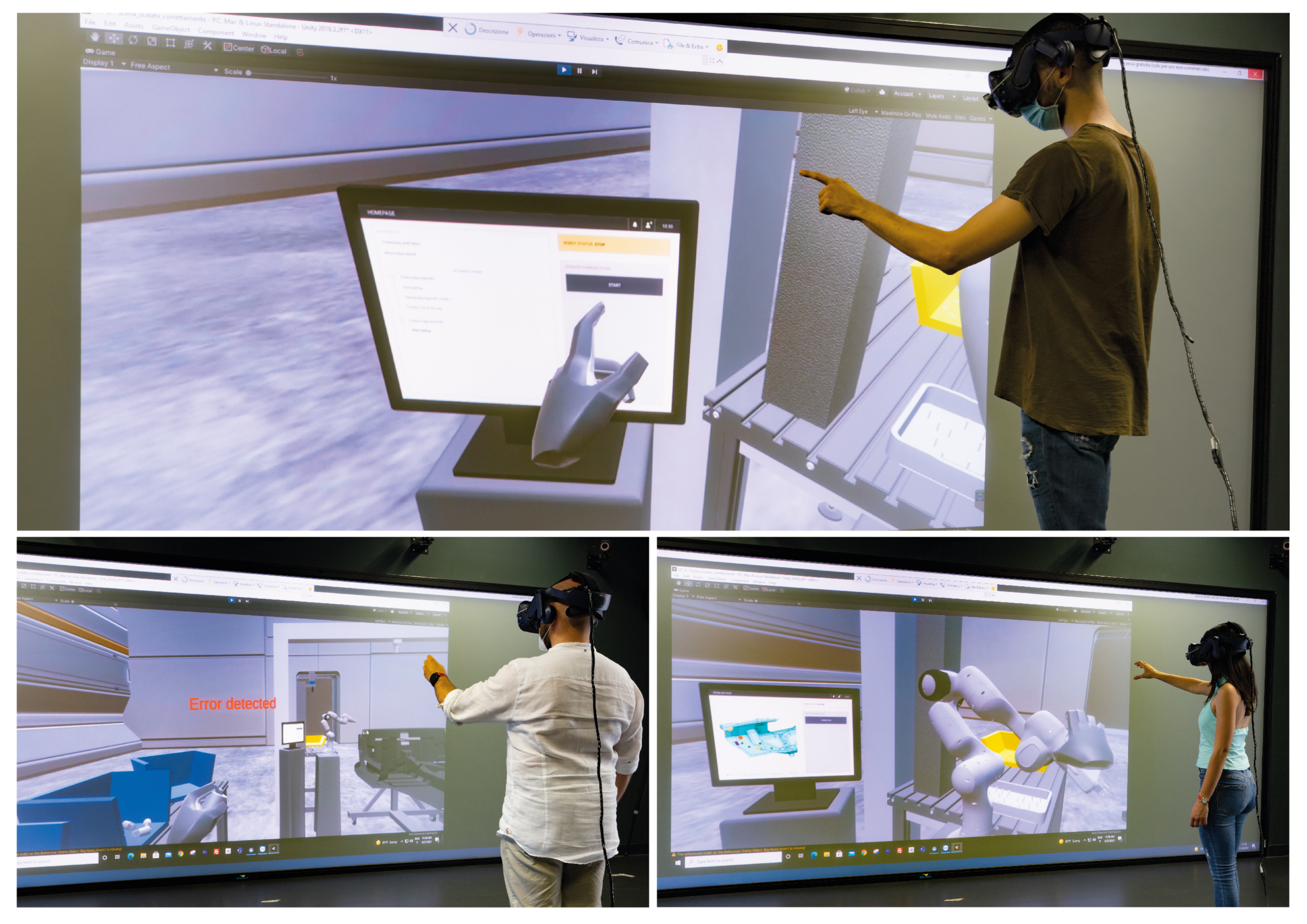
2.2.2. HMI Prototyping

Once the most suitable interface type for the specific context of use has been defined, the HMI design proceeds with the prototype development, initially at low-fidelity and then increasingly closer to the final result (high-fidelity). The purpose of this phase is the definition of the interaction flow, interface contents, information architecture, and interface appearance. For example, in the case of a graphic interface prototype, designers need to define which contents are to be displayed, how to divide and organize them in the various pages and finally what aspect to assign.
The low-fidelity prototype is an initial simplified version of the interface. Following the proposed approach, it can be created directly inside the VR scene to allow designers to facilitate the translation of the previously mapped information into the low-fidelity interface prototype. To this end, communication should be represented with simple elements (e.g., shapes, words), respecting the identified interaction positions, the timing and the interaction direction. For example, as shown in Figure 10, each communication can be associated with a simple interactive button to which the corresponding response of the components of the VR scene is connected. As an example, the interaction with the “Start button” must be connected to the beginning of the robot movement. However, this integration may involve reviews of previously created components animations. Even in the case of voice or gesture interfaces, communications could initially be simulated through either graphic elements or a combination of this and voice/gesture.
Once the interaction flow and the information architecture have been validated, it is possible to continue the interface design with a high-fidelity prototype. In this phase, the interface can be further detailed until the final result has been reached. For instance, in the case of graphic interfaces it consists of visual aspects design; in the case of speech interfaces it consists of keywords definitions and in case of gesture interfaces it consists of movements or haptic feedback. Based on the defined interface type and its complexity, at this stage it may be necessary to use dedicated software for interface design (e.g., Adobe XD in the case of graphic interface). When the final prototype has been achieved, it is necessary to import it, or a part of it, within the VR scenario for validation purposes. For a more realistic view, the 3D model of the defined interface device could be integrated and linked to the high-fidelity prototype. In fact, the high-fidelity prototype should be able to provide a realistic experience.

2.2.3. HMI Testing

Testing sessions are always a fundamental phase in the HMI design process [34]. In particular, user testing allows designers to understand HMI usability and to collect information about the UX. The latter is closely related to the context of use, especially for interfaces in a working complex scenario, such as in industry [35]. Anticipating the UX evaluation is fundamental especially when innovative workspaces are designed, such as the novel human-robot collaborative workstations. Within this context, VR offers a good solution for promptly assessing HMIs, considering the influence of the environment on interaction.
The proposed approach allows to include HMI testing in the VR scenario phase and follow a traditional qualitative approach [36], involving a limited number of participants to collect main feedback [37]. Qualitative testing goal is the collection of information about the users’ perception of the product (e.g., interface) in order to improve it and fix problems [36]. Indeed, the quality of the insights (e.g., users’ comments, suggestions, behavior, facial expressions) that emerge from the analysis is more important than objective results (e.g., task time execution, number of errors). For these test type, participants could be end-users (i.e., operators that will be involved in the new workstation) or other people available similar to the end-users profile. The participants’ profile choice depends also on the specific testing aspects and goals [33].
These kind of tests are structured in three main phases: pre-test participant data collection, task execution, and post-test questionnaire. The pre-test data collection aims at gathering all the necessary information about participants (e.g., age, working role, expertise level). These can change according to the specific project and considering what is more useful for a better interpretation of the collected data. Moreover, pre-test time could be used also to have the consent form signed. The task-execution phase involves the participant carrying out the defined tasks. These must not be too general or too specific, but leave the participant sufficient freedom to behave as he/she would normally do in a real work situation. In this phase, one member of the design team takes on the role of moderator while the rest take on the role of observers. The moderator has to indicate one at a time the tasks to be performed, without affecting the performance and remaining as neutral as possible [36]. Instead, it is essential for observers to collect everything that may be an indication of the HMI usability level. These may include the participant comments and his/her behavior during the interaction with the HMI (e.g., repetitive errors, indecision, surprise expression). During the task performance, specific devices can be used to collect participant physiological parameters in order to evaluate the stress level during the interaction [38]. Regarding the post-test phase, many questionnaires for the participant satisfaction investigation exist. Most of these involve evaluating graphical interfaces. Among the most used in this area are the Net Promoter Score (NPS), the System Usability Scale (SUS), the Usability Evaluation [39], the Usability Metric for User Experience (UMUX), and UMUX-LITE [40]. Furthermore, it is considered important that the post-test evaluation questionnaire also explores how much the VR scene has influenced the interaction with the HMI and the participant perception of it. In this regard, three main aspects to be investigated have been identified: the VR scene responsiveness, participant discomfort and quality of the sensorial stimulation, depending on the adopted tools (e.g., visual, auditory, haptic).

3. Application to Industrial Case Studies

In this section, we present the results obtained from the application of the proposed approach to two industrial cases, focusing on the design of human-robot collaborative spaces: an intensive warehouse (first case study) and a human-robot assembly station (second case study). Considering the goals of the case studies, we focus on different aspects for each case study: in the first, the goal is the layout prototype and it serves to demonstrate how the proposed approach can validly support the design of complex environments with rather simple human-machine interaction, hence we apply the first level of the proposed approach (presented in Section 2.1); whereas the second case study focuses on the design of a complex human-robot interaction in a rather simple environment, therefore we apply the second level of the proposed approach (presented in Section 2.2).

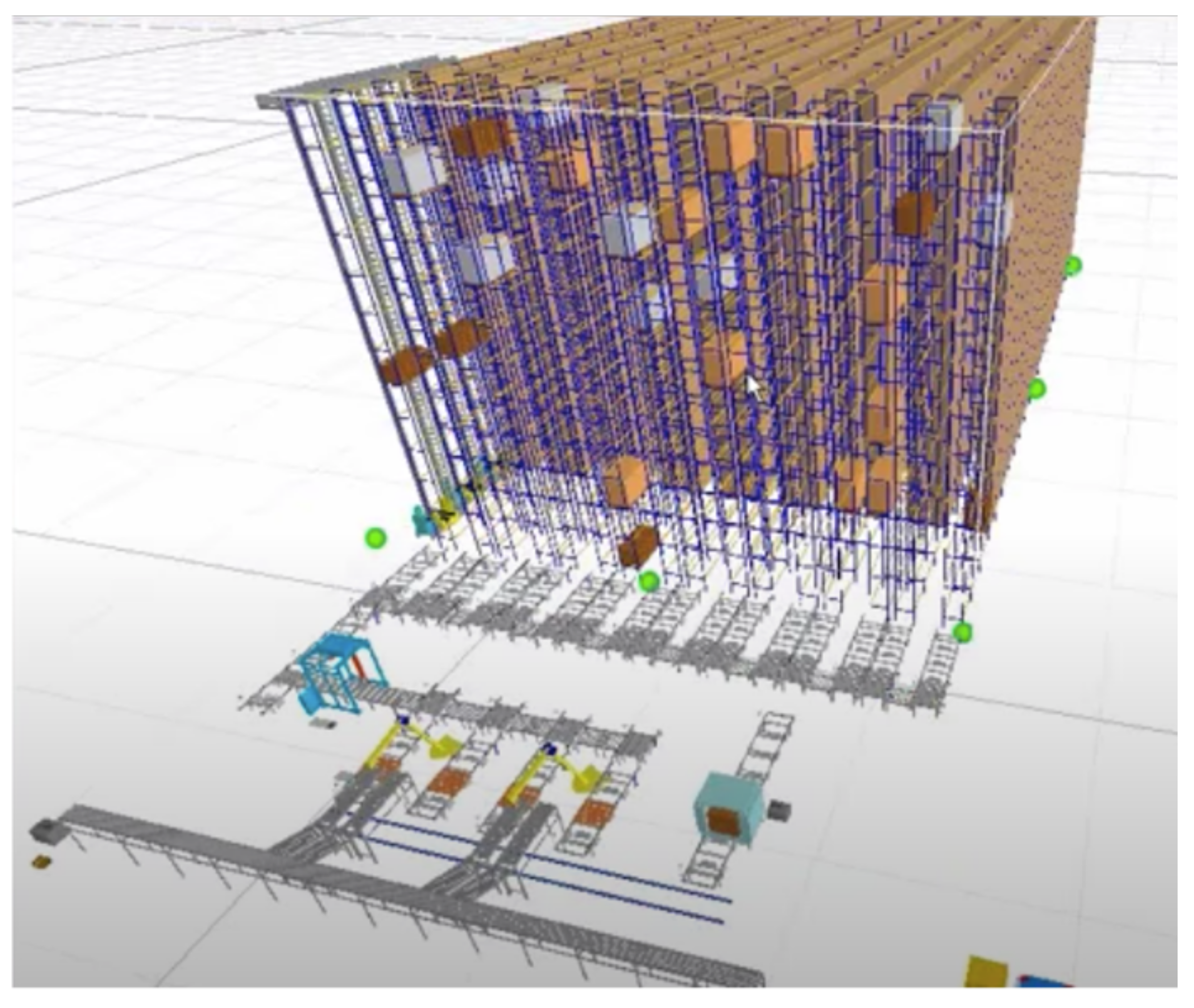
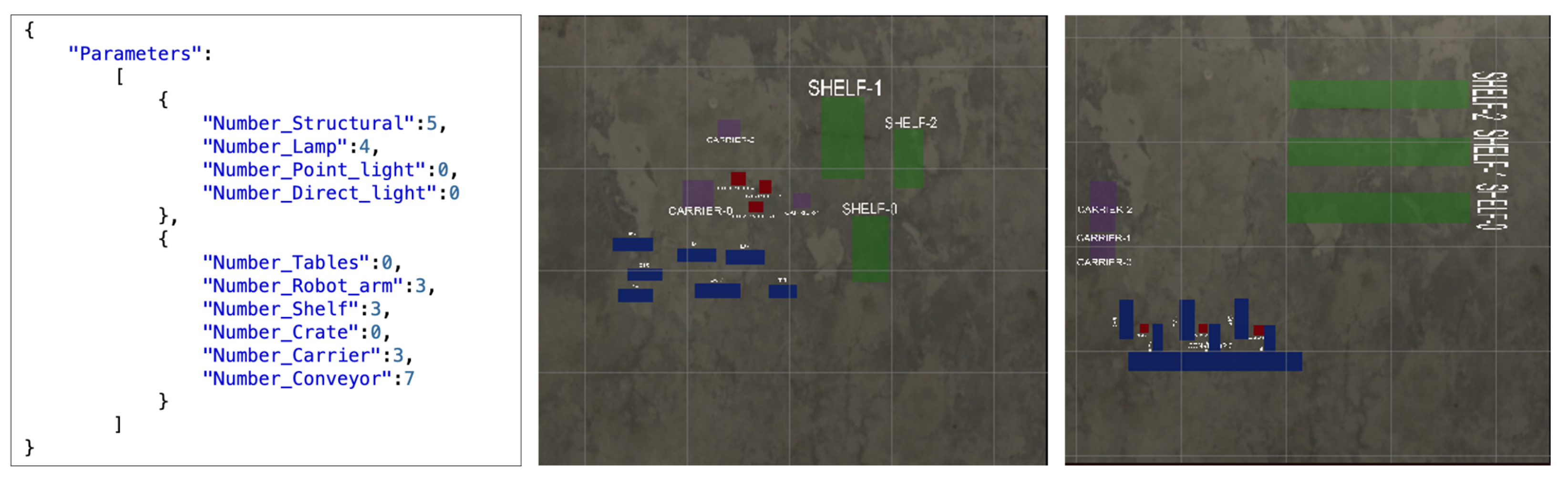
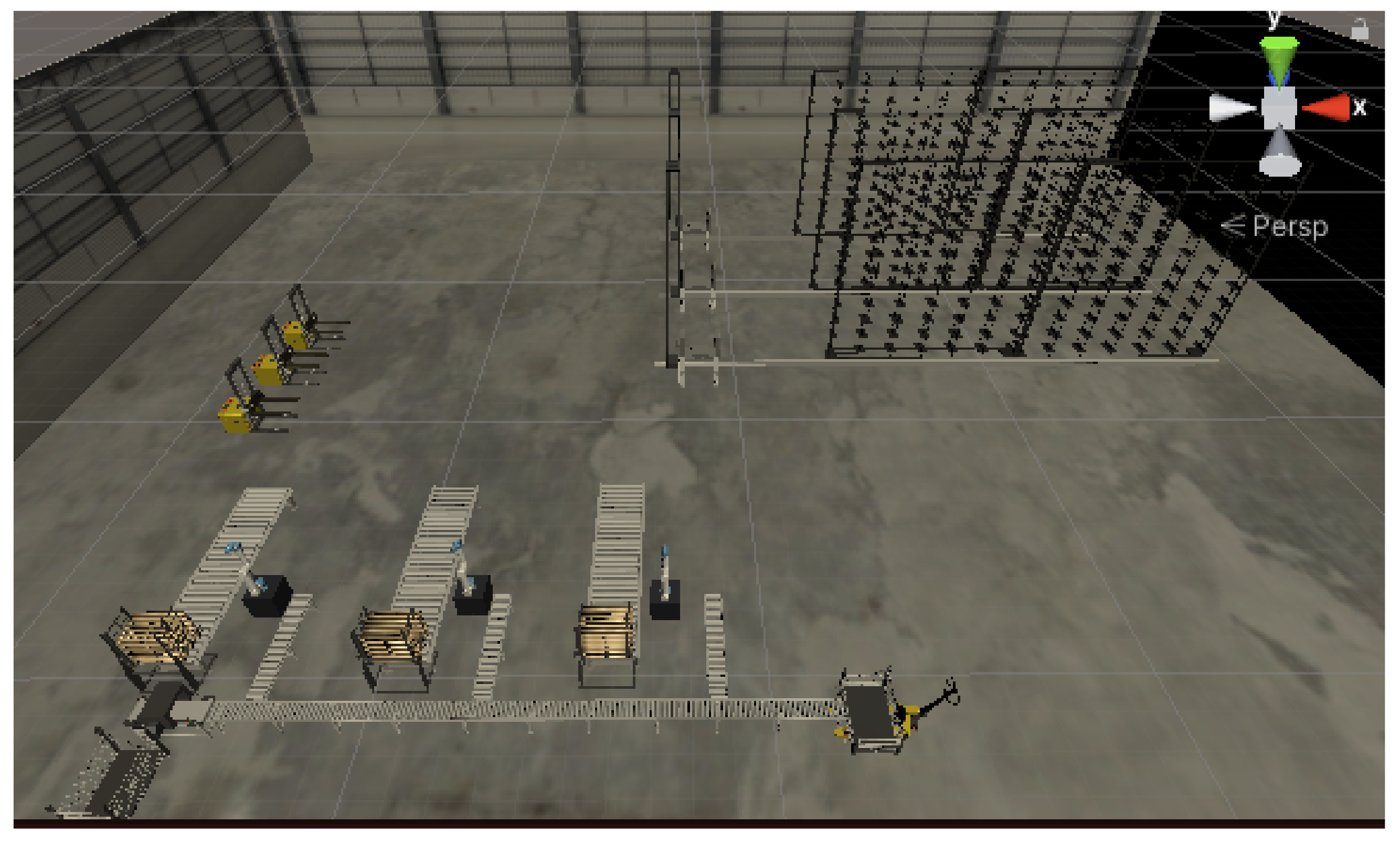
3.1. Case No.1: Complex Layout Prototyping for Intensive Warehouse

In the following, we adopt the approach proposed in Section 2.1 for the VR-based early and rapid prototyping of the physical layout of a workcell or a shopfloor. To this end, we consider an intensive warehouse, where boxes are unpacked and divided, goods are then arranged on pallets, which are then picked up and placed in a different area, before being stored. Figure 11 reports an example of how the desired warehouse should be: the idea is to reproduce a virtual interactive replica of this warehouse, in order to assess how to build it in a real environment. In other words, Figure 11 together with the short description of the warehouse functionality might represent the conceptual description of the desired scene, given by the designer (or their customer).
Following the general architecture depicted in Figure 2, as a first step it is needed to build a structured description of the scene and, hence, identify the main elements that will appear in it, together with their positions and sizes. To this end, we consider to use a conveyor belt from which three ways branch off leading to a robot arm each. The robot picks up the box and places it on another conveyor belt that has a pallet dispenser. When the pallet is completed, it is moved to the end of the conveyor. Here, an automated guided vehicle (AGV) picks up the pallet and presents it to stacker elevators, which, finally, load the pallet and bring it to the final shelf. As a result, the following elements are needed in the scene:
  • Five structural elements (i.e., ceiling and four walls);
  • Four lamps;
  • Seven segments of conveyor belt;
  • Three robot arms;
  • Three AGVs;
  • Three shelves for intensive warehouses (i.e., shelf and stacker elevator).
Given the list of required elements, it is hence possible to create the corresponding JSON description and, then, a preliminary 2D map of the environment, as shown in Figure 12. In the figure, the JSON file (left) is organized in two vectors to improve its readability: one includes Room elements, while the other includes those of type Furniture. Once this file has been created, by running the Management script in Unity it is possible to automatically create the 2D map. Information about size and position of the loaded elements can be decoded in JSON format and/or they can be set directly moving and resizing the objects in Unity. In this latter case, that is if no information about size and position is provided in the JSON structured description of the scene, items are located in positions in the 2D map (middle panel in Figure 12) and can be then moved through Unity interface, with mouse gestures or “Inspector” panel, in order to be placed in the most appropriate position (right).
Finally, it is possible to generate the 3D scene, which is shown in Figure 13. Changes to the 3D map can be easily done, as well, through Unity interface, with mouse gestures or “Inspector” panel.

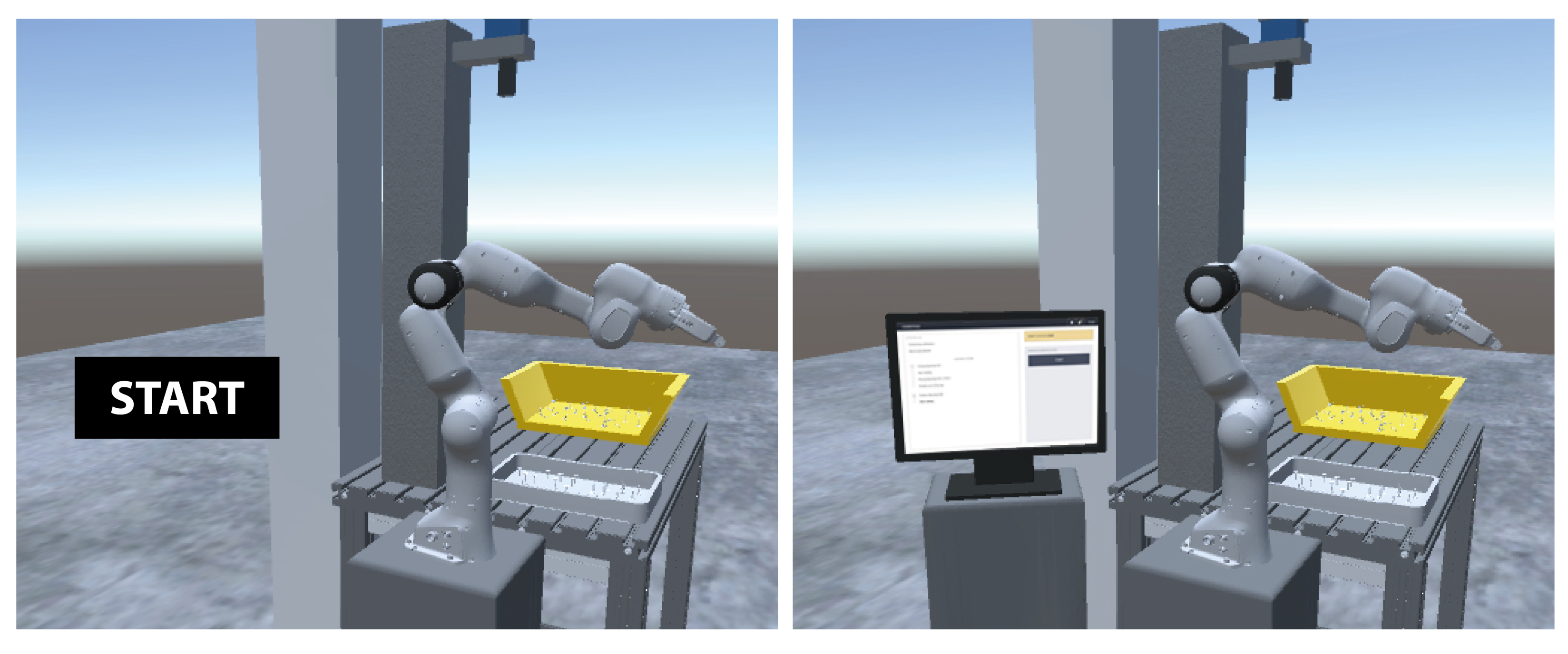
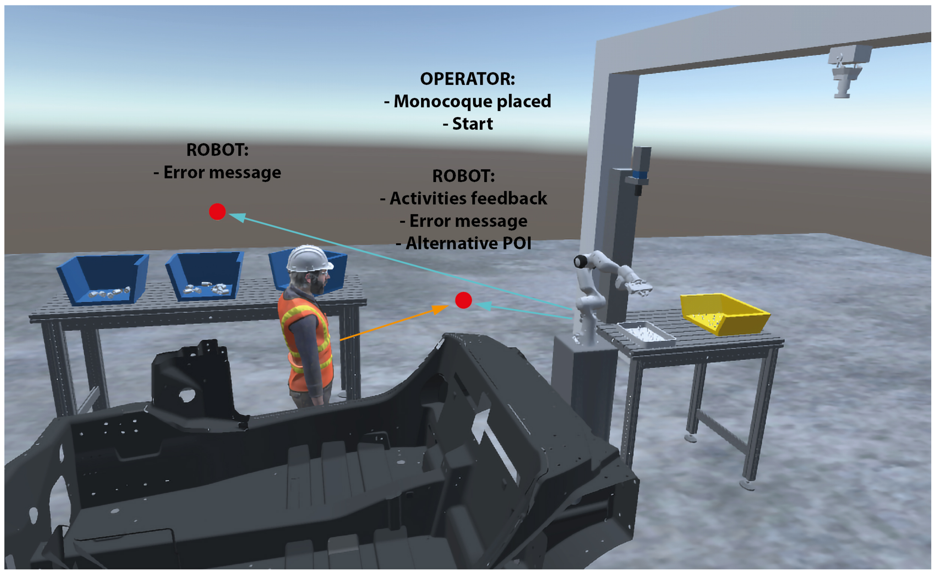
3.2. Case No.2: Interaction Prototyping for Human-Robot Assembly

The second case study presents how the proposed VR-based approach can be used to support the human-robot interface design for an industrial context. The case study concerns a collaborative human-robot assembly station. Specifically, an operator and a cobot are in charge of inserting bonding fastener (i.e., bigHead) on a monocoque of a car. The operator has the task of positioning the monocoque near the robot station and starting the automatic phase of the robot, while the robot autonomously applies the glue and places the bigHeads on the monocoque. During the automatic phase, the operator carries out parallel activities and has the task of supervising the robot operations, intervening in case of failure.
Although the focus of this scenario is on the design of the HMI to guarantee high-quality human-robot communications, as a first step we considered a possible physical layout of the workstation for this working scenario. To this end, the approach described in Section 2.1 was applied to identify the needed tools and their location in the environment. Specifically, the following elements were identified:
  • Two tables;
  • A cobot, with specific end-effector for bigHeads insertion;
  • Monocoque;
  • A glue dispenser;
  • A vision system.
Moreover, given that the focus of this virtual environment is to study and design human-robot communication and interaction, relevant items to be included in the scene are the human operator, wearing protective helmet and glasses, and background noise. The resulting 3D scene is represented in Figure 14. It is worthwhile noting that some these elements are very specific for this case study. Nevertheless, they can be easily integrated in the virtual scene, provided that a 3D sketch is available. The same is applied to situational factors, such as noise, personal protective equipment or the presence of a human, whose introduction is relevant in some applications.
Given the availability of a virtual rendering of the workstation, it is then possible to focus on the design of human tasks and interaction with the environment. The human-machine interaction mapping phase started from the scenario text description to understand all the necessary interaction aspects. From this, it emerges that the user must interact with both the robot and the system, mostly to receive constant updates on the activities completed by the robot. The communications that the user must send to the robot/system are limited to a few occasions, especially concerning troubleshooting. Initially, the operator must communicate to the system the correct positioning of the monocoque and start the automatic phase through the HMI. From this moment, the interactions are limited to the feedback communication from the robot about its activities and error messages. In case of robot failure during the bigHead application on the monocoque, the operator must intervene by completing the task in hand-guidance (i.e., accompanying the robotic arm towards the direction where to insert the bigHead until it recognizes it) or in hand-over (i.e., removal of the bigHead from the robot gripper and manual positioning). Especially in the hand-guidance phases, it is essential that the user visualizes the robot’s response to her/his actions. For this reason, the first identified interaction point to insert the HMI was on the robot station proximity, in order to be clearly visible during a collaborative task execution.
Moreover, considering that the operator carries out other parallel activities another interaction point was individuated. This does not correspond to a specific point but it is indicative that the operator could move in the work area, especially near the workbench. The choice of identifying a second interaction point is mainly linked to the case of problem signaling while the operator is carrying out other activities away from the robot’s workstation.
As regards the interaction moment, it is known that the user must interact with the HMI at the beginning to start the automatic phase, hypothetically on the first interaction point. Moreover, the HMI must be easily accessible throughout the work execution to receive feedback. Instead, it is unpredictable to know if and when the user will have to interact with the HMI to solve a problem.
Figure 14 shows the human-machine interaction mapping output of this case study. The interaction mapping led to the definition of two types of HMI: a graphic interface on a monitor (main HMI) to be placed near the collaborative robot, and a wrist wearable device for gesture/haptic interface. The first one is dedicated to all communication from/to users to/from robot and system, such as starting the automatic cycle or displaying the activities carried out by the robot. Instead, the second HMI is dedicated to reporting a problem to the operator and therefore to bring his/her attention to the main HMI. Initially, the hypothesis of a single mobile interface might have seemed suitable, but the big amount of information to visualize on the main interface, and the operator’s manual activities led to exclude this hypothesis.
The HMI design phase focused on the graphic interface (main HMI). At first, a low-fidelity prototype was developed using the VR software Unity. Secondly, a high-fidelity prototype was developed using one of the most used tools for interactive graphic interface prototyping called Adobe XD (https://www.adobe.com/products/xd.html, accessed on 23 November 2021), and then the screens were inserted in the VR scenario. The low fidelity prototype phase focused on the design of the interaction flow structure, therefore HMI screens only included the key elements that allow interactions. Starting from the human-machine interaction mapping, the individuated communications were translated into graphical elements. For example, the communications “monocoque placed” and “start” were translated using a button with the text “start” (Figure 15, second column, top image), and once the automatic phase has started, the stop button appears to allow the activity suspension. The “error message” communication was translated into a text that describes the problem and a button that opens the dedicated solving page (Figure 15, second column, middle image). In the same way, the “activities feedback” communications are simply represented in short text that appears and is updated (Figure 15, second column, bottom image). Subsequently, the HMI design was finalized during the high-fidelity prototype phase. The interface screens were enriched by adding other elements (e.g., page title, status bar) and visual aspects (e.g., colors, text size, components dimensions) which are fundamental to improve the interface comprehension, as well as its usability. For example, the start page was redesigned considering the communications and interactions after the starting, leading to a single page with the right side dedicated to the user inputs, and the left side dedicated at displaying the communications sent by the system (Figure 15, third column, top and bottom images). The communication of an error has been inserted in a pop-up window that appears above the main screen in order to always have access to the main information (Figure 15, third column, middle image).
Given the complexity of the industrial use context, the environment could significantly affect the HMI usability. For this reason, the high-fidelity prototype has been continuously included and evaluated in the VR scenario. For a more precise evaluation, we took on the user role, also performing his/her tasks in order to better understand the overall UX. These cyclic tests allowed to identify interaction aspects not previously considered, as well as problems and strengths of each interface page, therefore better understanding how to improve it. For example, it emerged that the user must be able to see the interface even from several meters and this affects the HMI design, such as reviewing the size of some elements (e.g., text, buttons).
Finally, referring to the third step of the VR-based interaction design approach, we conducted HMI testings. As described in Section 2.2.3, testings aimed at verifying the usability of the designed HMI and the overall user experience in the early VR-based prototype developed with the proposed approach. The HMI testing phase was conducted involving seven participants with different ages and familiarity with VR devices (Figure 16). In particular, participants were PhD students and research fellows, not directly involved in the research, of which two women and five men between 25 and 32 years old.
During the test, participants were guided by a moderator who explained the activities to be carried out in sequence. Task descriptions were pretty generic in order not to excessively influence the users and to leave them free to act. The sequence of tasks indicated to participants is:
  • Place the trolley with the monocoque near the robot;
  • Communicate the positioning on the HMI and verify that the automatic phase is started;
  • Carry out parallel activities (for example on the desk located on the left);
  • Resolve the reported problem;
  • Communicate the resolution of the problem;
  • Suspend the activity of the robot.
During the tests some participants expressed comments regarding the HMI interaction and the general activities performance. Some of the most helpful comments that emerged were:
  • “I expected to receive an indication of the exact positioning of the monocoque”;
  • “The interface was clear, but it has a rather limited appeal. I would like it more colorful”;
  • “I was expecting feedback on the successful completion of the hand guidance phase”;
  • “In the problem resolution screen, it was not clear that I had to do something like moving the robot in hand guidance”.
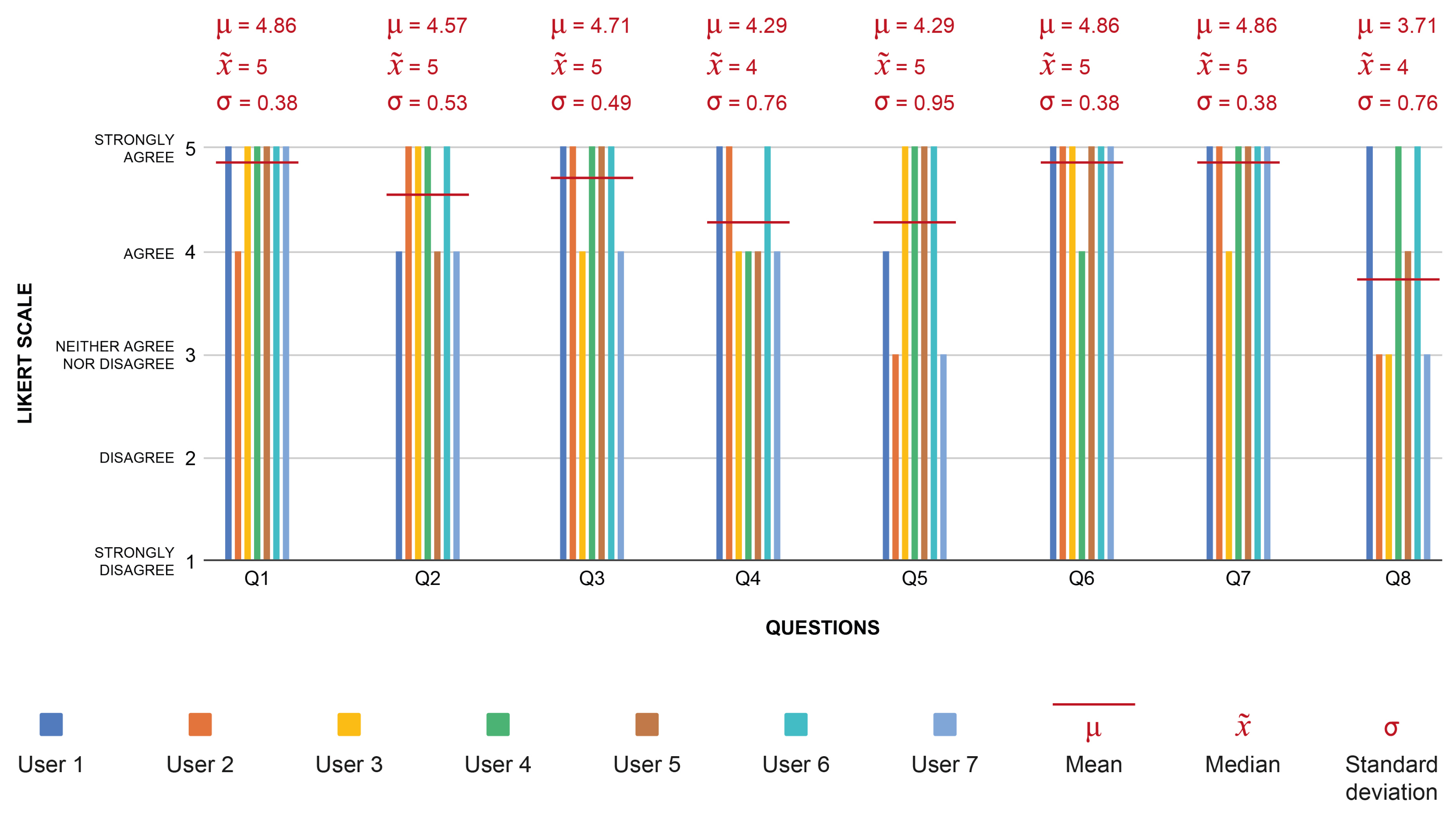
Moreover, after the tasks execution, participants were asked to fill in a questionnaire to better investigate the user perception about the HMI interactions and the overall user experience. The questionnaire was based on the SUS model [39] but it was customized to better suit the needs of the specific survey. For each following statements, participants were asked to express a degree of agreement on a 5-Point Likert Scale (i.e., 1 = Strongly disagree, 5 = Strongly agree):
Q1:
I think I would like to use the interface;
Q2:
I found the interface very clear;
Q3:
I found the interface easy to use;
Q4:
I felt safe in interacting with the interface;
Q5:
I think the type of interface is appropriate for the type of work;
Q6:
I think the interface provides me with all the information I need to do my tasks;
Q7:
I think that the interaction with the interface is not hindered by the surrounding environment;
Q8:
I think that the HMI evaluation is not influenced by the VR scene characteristics.
As mentioned in Section 2.2.3, at this design phase HMI testing mainly aims at qualitative data collection. In fact, more attention was given to the users’ comments and behavior as a source of suggestions for improving the interface. For example, a red border has been added to the problem management page to better differentiate it from other pages; the list of tasks that the user must perform has been included to better guide the user during the resolution of a problem; the title of the displayed page has been made more evident to facilitate orientation within the system. On the other hand, post-test questionnaire responses were analyzed to understand the users’ satisfaction level. The mean ( μ ), median ( x ˜ ) and the standard deviation ( σ ) were calculated for each question and they showed that involved users judge the interface with a good level of usability (Figure 17).
From these testing sessions, it emerged how the immersive VR scenario helped the participants to evaluate the interface quality as a whole and, more specifically, considering the real context of use. Indeed, some users comments are related to the interaction of the interface in parallel with other actions and probably considering the interface extrapolated from its context of use might not have brought out the same considerations.

4. Discussion and Conclusions

The considered case studies addressed two different realistic industrial scenarios in order to provide a preliminary validation of the proposed approach and concretely describe its application. The two case studies were selected for their diverse typology and goals: in the former case, we considered the need to design an intensive warehouse and, while in the latter case we focused on an assembly workstation where different agents, namely a human operator and a robot, interact and collaborate on the same task. These case studies are representative of two common, although different, scenarios: a large shop floor where it is likely that space needs to be reorganized frequently to accommodate flexible production, and a collaborative workstation where interactions among operators, system, and robots are part of the design task. The application of the proposed approach to such case studies has shown how it is suited to address these objectives, either separately or jointly.
In particular, the first case study has shown how it is possible to obtain an interactive scene of a complex environment starting from an high-level description of required functionalities. As a result, the use of the proposed approach allows for a quick reconfiguration of any work environment due to changes in production batches. The advantages are twofold. On the one side, it is possible to have a clear view of the physical layout of a work environment far before its physical realization, as soon as its functionalities are clear at a high-level. Thus, such a view can be available to designers, or customers or architects, in the very early phases of the design, and changes can be easily applied and viewed in interactive mode by means of VR. On the other side, the availability of an early prototyping system allows to reduce cell downtime, which is particularly convenient in cases of agile production.
Additionally, the second case study has demonstrated that VR provides significant added value when a manufacturing process requires user interaction with machines or robots. In particular, VR turns out to be helpful in each phase of the user interfaces design flow. The reproduction in VR of contexts where user interfaces are going to be used is helpful to study interaction processes and user’s reactions towards different interaction tools and modalities. Moreover, the design team can act as end user in the working environment and freely interact with the interface. This aspect allows a better understanding of the user’s needs during the interaction with the surrounding environment and working tools in a reliable replica of the realistic working scenario. As a result, the characteristics the user interfaces should have to facilitate the interactions and improve the UX can be assessed and included in the design of the working environment.
In conclusion, the proposed approach serves as an integrated framework to support the design of working environments both from a functional and user points of view. As regards the functional aspect, thanks to the case no.1 we found that the physical layout of the scene can be easily optimized in the VR scene at no costs in terms of machines downtime. As regards the interaction aspects, the proposed approach allows to easily include user requirements related to interaction with machines and robots as an input for design, rather than as a secondary adjustment to the output of workstation design. The considered use cases have been driven by two companies, in the context of two different research projects, to provide a preliminary validation of the proposed approach. Further investigation will be done as future works to refine the approach and propose a more detailed methodology, supported by data and experimental results, also involving a bigger user samples. This step will allow to concretely apply the proposed approach for the design of real industrial environments.

Author Contributions

Methodology, M.P. and V.V.; software, E.P. and V.V.; validation, E.P., V.V.; writing—original draft preparation, E.P. and V.V.; writing—review and editing, M.P. and L.S.; supervision, M.P and L.S.; project administration, L.S. All authors have read and agreed to the published version of the manuscript.

Funding

This work was supported by the ICOSAF Collaborative Project through the Italian Ministry for University and Research, and by the COLLABORATION Project through the Italian Ministry of Foreign Affairs and International Cooperation.

Institutional Review Board Statement

Not applicable.

Informed Consent Statement

Informed consent was obtained from all subjects involved in the study.

Conflicts of Interest

The authors declare no conflict of interest.

References

  1. Matheson, E.; Minto, R.; Zampieri, E.G.; Faccio, M.; Rosati, G. Human–robot collaboration in manufacturing applications: A review. Robotics 2019, 8, 100. [Google Scholar] [CrossRef] [Green Version]
  2. Goodrich, M.A.; Schultz, A.C. Human-Robot Interaction: A Survey; Now Publishers Inc.: Delft, The Netherlands, 2008. [Google Scholar]
  3. Thrun, S. Toward a framework for human-robot interaction. Hum.-Comput. Interact. 2004, 19, 9–24. [Google Scholar]
  4. Fraboni, F.; Gualtieri, L.; Millo, F.; De Marchi, M.; Pietrantoni, L.; Rauch, E. Human-Robot Collaboration During Assembly Tasks: The Cognitive Effects of Collaborative Assembly Workstation Features. In Proceedings of the Congress of the International Ergonomics Association, online, 13–18 June 2021; pp. 242–249. [Google Scholar]
  5. Harriott, C.E.; Buford, G.L.; Adams, J.A.; Zhang, T. Mental workload and task performance in peer-based human-robot teams. J.-Hum.-Robot. Interact. 2015, 4, 61–96. [Google Scholar] [CrossRef] [Green Version]
  6. Krüger, J.; Lien, T.K.; Verl, A. Cooperation of human and machines in assembly lines. CIRP Ann. 2009, 58, 628–646. [Google Scholar] [CrossRef]
  7. Raymond, L.; St-Pierre, J. Antecedents and performance outcomes of advanced manufacturing systems sophistication in SMEs. Int. J. Oper. Prod. Manag. 2005, 25, 514–533. [Google Scholar] [CrossRef]
  8. Yin, Y.; Stecke, K.E.; Li, D. The evolution of production systems from Industry 2.0 through Industry 4.0. Int. J. Prod. Res. 2018, 56, 848–861. [Google Scholar] [CrossRef] [Green Version]
  9. Lattanzi, L.; Raffaeli, R.; Peruzzini, M.; Pellicciari, M. Digital twin for smart manufacturing: A review of concepts towards a practical industrial implementation. Int. J. Comput. Integr. Manuf. 2021, 34, 567–597. [Google Scholar] [CrossRef]
  10. Dianatfar, M.; Latokartano, J.; Lanz, M. Review on existing VR/AR solutions in human-robot collaboration. Procedia CIRP 2021, 97, 407–411. [Google Scholar] [CrossRef]
  11. Villani, V.; Pini, F.; Leali, F.; Secchi, C. Survey on human–robot collaboration in industrial settings: Safety, intuitive interfaces and applications. Mechatronics 2018, 55, 248–266. [Google Scholar] [CrossRef]
  12. Wonsick, M.; Padir, T. A Systematic Review of Virtual Reality Interfaces for Controlling and Interacting with Robots. Appl. Sci. 2020, 10, 9051. [Google Scholar] [CrossRef]
  13. De Giorgio, A.; Romero, M.; Onori, M.; Wang, L. Human-machine collaboration in virtual reality for adaptive production engineering. Procedia Manuf. 2017, 11, 1279–1287. [Google Scholar] [CrossRef]
  14. Gammieri, L.; Schumann, M.; Pelliccia, L.; Di Gironimo, G.; Klimant, P. Coupling of a redundant manipulator with a virtual reality environment to enhance human-robot cooperation. Procedia CIRP 2017, 62, 618–623. [Google Scholar] [CrossRef]
  15. Matsas, E.; Vosniakos, G.C.; Batras, D. Modelling simple human-robot collaborative manufacturing tasks in interactive virtual environments. In Proceedings of the 2016 Virtual Reality International Conference, Laval, France, 23–25 March 2016; pp. 1–4. [Google Scholar]
  16. Wang, Q.; Cheng, Y.; Jiao, W.; Johnson, M.T.; Zhang, Y. Virtual reality human-robot collaborative welding: A case study of weaving gas tungsten arc welding. J. Manuf. Process. 2019, 48, 210–217. [Google Scholar] [CrossRef]
  17. Dimitrokalli, A.; Vosniakos, G.C.; Nathanael, D.; Matsas, E. On the assessment of human-robot collaboration in mechanical product assembly by use of Virtual Reality. Procedia Manuf. 2020, 51, 627–634. [Google Scholar] [CrossRef]
  18. Pérez, L.; Diez, E.; Usamentiaga, R.; García, D.F. Industrial robot control and operator training using virtual reality interfaces. Comput. Ind. 2019, 109, 114–120. [Google Scholar] [CrossRef]
  19. Prati, E.; Peruzzini, M.; Pellicciari, M.; Raffaeli, R. How to include User eXperience in the design of Human-Robot Interaction. Robot.-Comput.-Integr. Manuf. 2021, 68, 102072. [Google Scholar] [CrossRef]
  20. Daria, B.; Martina, C.; Alessandro, P.; Fabio, S.; Valentina, V.; Zennaro, I. Integrating mocap system and immersive reality for efficient human-centred workstation design. IFAC-PapersOnLine 2018, 51, 188–193. [Google Scholar] [CrossRef]
  21. Caputo, F.; Greco, A.; D’Amato, E.; Notaro, I.; Spada, S. On the use of Virtual Reality for a human-centered workplace design. Procedia Struct. Integr. 2018, 8, 297–308. [Google Scholar] [CrossRef]
  22. Peruzzini, M.; Carassai, S.; Pellicciari, M. The benefits of human-centred design in industrial practices: Re-design of workstations in pipe industry. Procedia Manuf. 2017, 11, 1247–1254. [Google Scholar] [CrossRef]
  23. Grajewski, D.; Górski, F.; Zawadzki, P.; Hamrol, A. Application of virtual reality techniques in design of ergonomic manufacturing workplaces. Procedia Comput. Sci. 2013, 25, 289–301. [Google Scholar] [CrossRef] [Green Version]
  24. Menck, N.; Yang, X.; Weidig, C.; Winkes, P.; Lauer, C.; Hagen, H.; Hamann, B.; Aurich, J. Collaborative factory planning in virtual reality. Procedia CIRP 2012, 3, 317–322. [Google Scholar] [CrossRef] [Green Version]
  25. Gavish, N.; Gutiérrez, T.; Webel, S.; Rodríguez, J.; Peveri, M.; Bockholt, U.; Tecchia, F. Evaluating virtual reality and augmented reality training for industrial maintenance and assembly tasks. Interact. Learn. Environ. 2015, 23, 778–798. [Google Scholar] [CrossRef]
  26. Loch, F.; Vogel-Heuser, B. A virtual training system for aging employees in machine operation. In Proceedings of the 2017 IEEE 15th International Conference on Industrial Informatics (INDIN), Emden, Germany, 24–26 July 2017; pp. 279–284. [Google Scholar]
  27. Berg, L.P.; Vance, J.M. Industry use of virtual reality in product design and manufacturing : A survey. Virtual Real. 2017, 21, 1–17. [Google Scholar] [CrossRef]
  28. Bruno, F.; Muzzupappa, M. Product interface design: A participatory approach based on virtual reality. Int. J.-Hum.-Comput. Stud. 2010, 68, 254–269. [Google Scholar] [CrossRef]
  29. Morra, L.; Lamberti, F.; Pratticó, F.G.; La Rosa, S.; Montuschi, P. Building trust in autonomous vehicles: Role of virtual reality driving simulators in HMI design. IEEE Trans. Veh. Technol. 2019, 68, 9438–9450. [Google Scholar] [CrossRef]
  30. Shi, Y.; Azzolin, N.; Picardi, A.; Zhu, T.; Bordegoni, M.; Caruso, G. A Virtual Reality-based Platform to Validate HMI Design for Increasing User’s Trust in Autonomous Vehicle. Comput.-Aided Des. Appl. 2020, 18, 502–518. [Google Scholar] [CrossRef]
  31. Stadler, S.; Cornet, H.; Huang, D.; Frenkler, F. Designing Tomorrow’s Human-Machine Interfaces in Autonomous Vehicles: An Exploratory Study in Virtual Reality. In Augmented Reality and Virtual Reality; Springer: Cham, Switzerland, 2020; pp. 151–160. [Google Scholar]
  32. Prati, E.; Villani, V.; Peruzzini, M.; Sabattini, L. Use of interaction design methodologies for human-robot collaboration in industrial scenarios. IEEE Trans. Autom. Sci. Eng. 2021. [Google Scholar] [CrossRef]
  33. Prati, E.; Grandi, F.; Peruzzini, M. Usability Testing on Tractor’s HMI: A Study Protocol. In Proceedings of the International Conference on Human-Computer Interaction, Virtual Event, 24–29 July 2021; pp. 294–311. [Google Scholar]
  34. Villani, V.; Lotti, G.; Battilani, N.; Fantuzzi, C. Survey on usability assessment for industrial user interfaces. IFAC-PapersOnLine 2019, 52, 25–30. [Google Scholar] [CrossRef]
  35. Villani, V.; Capelli, B.; Sabattini, L. Use of virtual reality for the evaluation of human-robot interaction systems in complex scenarios. In Proceedings of the 2018 27th IEEE International Symposium on Robot and Human Interactive Communication (RO-MAN), Nanjing, China, 27–31 August 2018; pp. 422–427. [Google Scholar]
  36. Barnum, C.M. Usability Testing Essentials: Ready, Set... Test! Morgan Kaufmann: Burlington, MA, USA, 2020. [Google Scholar]
  37. Nielsen, J.; Landauer, T.K. A mathematical model of the finding of usability problems. In Proceedings of the INTERACT’93 and CHI’93 Conference on Human Factors in Computing Systems, Amsterdam, The Netherlands, 24–29 April 1993; pp. 206–213. [Google Scholar]
  38. Grandi, F.; Zanni, L.; Peruzzini, M.; Pellicciari, M.; Campanella, C.E. A Transdisciplinary digital approach for tractor’s human-centred design. Int. J. Comput. Integr. Manuf. 2020, 33, 377–397. [Google Scholar] [CrossRef]
  39. Albert, W.; Tullis, T. Measuring the User Experience: Collecting, Analyzing, and Presenting Usability Metrics; Newnes: London, UK, 2013. [Google Scholar]
  40. Borsci, S.; Federici, S.; Bacci, S.; Gnaldi, M.; Bartolucci, F. Assessing user satisfaction in the era of user experience: Comparison of the SUS, UMUX, and UMUX-LITE as a function of product experience. Int. J.-Hum.-Comput. Interact. 2015, 31, 484–495. [Google Scholar] [CrossRef]
Figure 1. Proposed technical approach.
Applsci 11 11773 g001
Figure 2. Block diagram of VR-based rapid prototyping of the workstation.
Applsci 11 11773 g002
Figure 3. Example of a 2D map as output of the second step of the proposed approach.
Applsci 11 11773 g003
Figure 4. Unity user interface.
Applsci 11 11773 g004
Figure 5. The number of elements in the desired scene is automatically extracted from the JSON description scene (left) and reported in Unity (right) through the Management script.
Applsci 11 11773 g005
Figure 6. “Inspector” panel of the Sketch GameObject, where the feature of each element are automatically extracted from the JSON description.
Applsci 11 11773 g006
Figure 7. “Inspector” panel for Room (left) and Furniture (right) GameObjects in the 3D scene.
Applsci 11 11773 g007
Figure 8. Three-dimensional model of aggregated GameObjects, with the corresponding nested hierarchy.Left: example of a robot arm; right: example of a carrier.
Applsci 11 11773 g008
Figure 9. Example of VR-based interaction mapping.
Applsci 11 11773 g009
Figure 10. Low fidelity prototype (on the left) and high fidelity prototype (on the right) examples.
Applsci 11 11773 g010
Figure 11. Reference warehouse for case no.1: using the approach described in Section 2.1, the goal is to reproduce a virtual replica to be used as an early prototype of the physical warehouse.
Applsci 11 11773 g011
Figure 12. Structured description of the desired scene (left) and 2D map with default (middle) and desired (right) positioning of elements for case no.1. Elements can be moved around the scene and resized either through JSON description or Unity interface.
Applsci 11 11773 g012
Figure 13. Three-dimensional prototype of the desired warehouse (see Figure 11) for case no.1, developed according the proposed approach.
Applsci 11 11773 g013
Figure 14. Human-machine interaction mapping of case no.2.
Applsci 11 11773 g014
Figure 15. Interface design flow with some screens of the low-fidelity and high-fidelity prototypes of the case no.2.
Applsci 11 11773 g015
Figure 16. Pictures of three testing sessions for case no.2.
Applsci 11 11773 g016
Figure 17. Questionnaire results for case no.2.
Applsci 11 11773 g017
Table 1. Contributes from literature.
Reference No.Application AreaMain Results
[20]Industrial workplacesErgonomic assessment of future workplace solutions
[21]Automotive assembly linesBiomechanical effort and ergonomics assessment
[22]Pipe industryPhysical and cognitive ergonomics optimization
[23]Industrial workplacesWorkplace design assessment
[24]Industrial workplacesFactory planning
[25]Industrial maintenance and assemblyTraining and support of operators
[26]Industrial workplacesTraining of operators
[27]Industrial workplacesProduct and process design
[28]Product interface designParticipatory interface design
[29]Autonomous VehiclesUser’s level of trust testing
[30]Autonomous VehiclesUser’s level of trust testing
[31]Autonomous VehiclesHMI concept testing
Table 2. Reference list of possible elements to include in the VR scene.
ElementDescription
FloorIt defines the size of the area to create. It is not an optional item and must be added in any scene. It corresponds to a surface, to be used as floor.
StructuralIt defines walls and ceiling.
Directional LightIt simulates outdoor light, made of parallel and infinite rays. It is incident on any element in the scene.
LampIt is pointwise light used to simulate lamps that can illuminate a limited area around.
TableIt represents any flat surface that can be used as worktable.
ShelfIt includes any type of shelves.
CrateIt includes any box.
CarrierIt includes any tool that can be used to move items, such as pallet jacks, forklifts and automated guided vehicles.
Robot armIt includes any type of robot arms.
ConveyorIt is specific for conveyors and can be used to create complex networks and arrangements of conveyor belts.
Situational factorsThey include, for example, the presence of noise, dust or other environmental conditions, and of human agents, with any possible personal protective equipment.
Publisher’s Note: MDPI stays neutral with regard to jurisdictional claims in published maps and institutional affiliations.

