Article

Conduction Transformation-Based Coordination Method for Conflict in Product Adaptive Design Driven by Functional Requirements

1
College of Mechanical Engineering, Quzhou University, Quzhou 324000, China
2
Key Laboratory of Ministry of Education/Zhejiang Province on Special Equipment and Advanced Manufacturing Technology, Zhejiang University of Technology, Hangzhou 310014, China
*
Author to whom correspondence should be addressed.
Appl. Sci. 2021, 11(24), 11757; https://doi.org/10.3390/app112411757
Submission received: 29 September 2021 / Revised: 2 December 2021 / Accepted: 6 December 2021 / Published: 10 December 2021

Abstract

:
A conduction transformation-based coordination method for product structure optimization design was proposed for the conflict between satisfying product functional requirements and realizing adaptive modification. Customer functional requirements were analyzed hierarchically, the extension domains that indicated the matching degree between customer requirement and product function were delimited; and then a multi-layer function-behavior-structure (FBS) mapping model was established. Product function-structure correlation analysis was carried out in two dimensions, i.e., “structure-structure”, and “structure-function”; a product structure behavior function (SBF) reverse conduction model was constructed based on FBS decomposition model; thus, to realize reverse conduction from structure layer to function layer. For conflict coordination in structure modification, extension transformation operations were created, the conduction transformation trigger unit was extracted, and the trigger condition was also clarified; thus, the coordination strategy for the contradiction in adaptive design could be generated by conducting active and conduction transformations. Finally, the effectiveness and feasibility of this method were verified with the structure optimization design of a delivery system of cutting machine as an example; and the discussion section emphasized that this proposed method used conduction transformation to address design conflict, instead of generating the optimal change propagation path, and how to obtain innovation inspiration.

1. Introduction

The realization of function is the intention of product design, and it is an important research content in both conceptual design and adaptive design of product [1]. For development of a mechanical product, the function is the main embodiment of the value of the product and is also an important reference basis for a customer to select the product. For product design, customer functional requirements have become the main driving factors for the modification of product. Adaptive designs can be divided into two categories, i.e., initial adaptive design, and adaptive modification design, by analyzing the references of product adaptive design. Initial adaptive design is to take into account the changed requirements and operating conditions in the use stage after product finalization in the initial stage of product design [2,3], whereas adaptive modification design is to lay particular emphasis on implementing structure modification design of finalized product based on the requirements or operating conditions [4,5].
The existing product designs in manufacturing industry are mostly adaptive modification designs, in other words, the improvement of function is realized by modification design of structure on the base of the original product; thus, to satisfy the corresponding customer functional requirements [6,7,8]. The essence of product adaptive modification is to realize the innovation of the original design scheme, and design contradictory problem is dealt with through the new provided design scheme. The contradictory problem mainly comes from two aspects, on the one hand, the current design scheme cannot meet the design requirement, on the other hand, there are conflicting performance elements in the process of adaptive modification. For instance, when a certain functional performance is improved, the other related performance is deteriorated.
The reason for the above design conflict is that the underlying structure of the product is related to each other, when the attribute parameters of structure are modified or the structure layout is changed, the related structural modules and the functional performance will be affected. Product structure changes and change propagation problems are common in product design [9]. In the field of engineering change research, four aspects of research work have been focused on product design changes: research on the change propagation path [10,11,12,13], change propagation impact analysis [14,15,16], change propagation prediction [17,18,19], change propagation management [20,21,22]. For example, Koh et al. [23] combined with the house of quality to evaluate the impact of change propagation. Li et al. [24] presented a design idea of parallel change propagation to reduce prediction time. Eisa at al. [25] analyzed the change propagation causes and determined the key influencing variables from two stages of product life cycle, i.e., development and production, so as to reduce change propagation from the perspective of predicting key influencing variables. In the context of engineering change management, Eltaief et al. [26] established the communication of engineering changes from parts to assemblies and elaborated the computer aided design (CAD) management model.
Conduction prediction provided change reference for designers, and could better reduce the actual change risk, to raise the adaptive modification efficiency. This method focused on how to predict the conduction scope or conduction influence degree of engineering change but lacked systematic and procedural research efforts on the acquisition of change driving factors and how to implement coordination of design contradictions in change propagation. Extenics combines mathematics, philosophy and engineering to provide a systematic solution framework for solving contradictory problems [27,28]. Extension design is the engineering application of Extenics in the field of design, change is defined as transformation in extension design, and change propagation is defined as conduction transformation, namely, the change or transformation of a certain structural parameter of the product will cause the conduction transformation of the relevant structural parameters [29,30,31]. For instance, Zhao et al. [32] adopted propagation analysis method to solve design conflict to satisfy product performance requirements. Zhou et al. [33,34] proposed an extension conduction transformation method for conflict in product performance design to coordinate the conflict problem. Tang et al. [35] established related conduction inference rules and conduction effect calculation model for conduction transformation occurring in addressing complex system conflict. Gong et al. [36] analyzed the conduction transformation for the structural modules, and further carried out the structure-function elements synthesis and structural design.
On the other hand, in a design activity, the mapping of requirement function to product structure is complicated, and a straightforward relationship cannot be established from function to a specified structure. Components are interacted in a variety of ways to achieve one or more functions, and thus, different design parameters and layout of components will affect the related structural modules and functional performance. When considering the non-functional requirements, the interactions between components will be further complicated. Therefore, terms such as “ill-structured”, “wicked problems” are used to describe the mapping from function onto structure in the design problem [37].
The contribution of this paper is to establish a multi-layer FBS mapping model, as well as a structure-structure, structure-function correlation analysis model, and provide a conduction transformation-based coordination strategy for design contradictions in adaptive design. At first, a quantitative matching mechanism between user requirements and product functions was established based on the dependent function, and then the product function was decomposed into multi-layer FBS units, which was useful to clarify specific structural units corresponding to each product function in adaptive modification compared with the original single-layer FBS model [38]. In traditional change propagation research, in order to obtain the optimal change path, the correlation between structures was usually analyzed and the correlation network could be established. However, these research works lacked the analysis of structure-function correlation [39,40]. This paper adopted design structure matrix (DSM) to analyze the correlation between structures, and the basic-element model was used to represent the information of each structure element in the DSM; in addition, a structure-behavior-function feedback model was constructed based on the multi-layer FBS model, which fed back the matching information of the upper-level functional requirement to the lower-level structure modification effect. Product adaptive design needed to modify the corresponding structural scheme to meet the new user requirements. In the process of modification, design contradictions would inevitably be encountered due to the correlation between structures. Case-based reasoning method was commonly used to reuse the previous design knowledge and rapidly generate the design scheme; but CBR was an incremental approach, and it relied on the case knowledge of the case library [41]. This research work introduced the Extenics to solve the contradictory problems for the product adaptive design, which consisted of creating the extension transformation operation, extracting the conduction transformation trigger unit, and clarifying the trigger condition; the strategy for the design contradiction could be generated by conducting the active and conduction transformation operations.
The rest of this article was organized as follows. The requirements and functions matching mechanism was constructed in Section 2, the correlation between structure and structure, structure and function were analyzed in Section 3, and the conduction transformation-based coordination strategy for product structure was provided in Section 4. Next section demonstrated the effectiveness of the proposed method by a case study, where the requirement function of cutting and moving of the cutting machine was satisfied with the conduction transformation strategy. Discussion was given, and conclusion was finally drawn along with the recommendation for further research.

2. Construction of Customer Requirement-Product Function Matching Mechanism

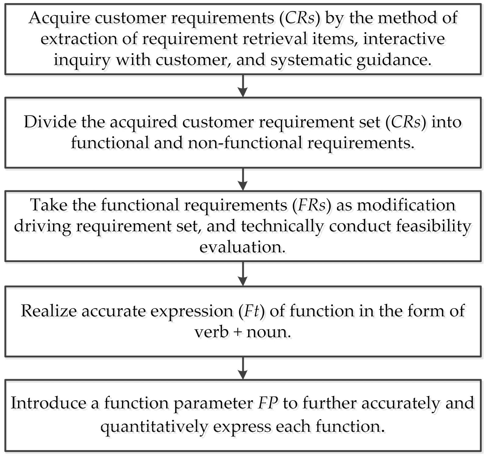
2.1. Analysis of Customer Functional Requirements and Delimiting of Extension Sets

Customer functional requirements (FRs) were used as the driving factors for product modification, so in this paper, analysis of FRs was focused on in the customer requirements (CRs) analysis stage, with non-functional requirements (NFRs) not taken into account temporarily. Figure 1 shows the hierarchical analysis of requirements, and the specific flow chart is shown in Figure 2.
In Figure 1, CRi was defined as the FR or NFR, this research work focused on the hierarchal analysis for the FRs; and each FRi could be described with the form Ftj, that is verb + noun; and Ftj contained one or more function parameters FPs. The analysis flowchart in Figure 2, CRs were firstly collected and then classified into the FRs or NFRs; FRs were taken as the driving factors for structure modification; the form of Ft was adopted to represent each FR, and FP was used to quantitatively evaluate Ft and FR.
For a specific product, the specific use function may have some deviation from the original customer requirement. Consequently, in order to quantify the matching degree between actual function and customer requirement, a customer requirement-product function matching mechanism was constructed by the extension dependent function to express product function domain via extension set.
Definition 1.
Assuming that U is the universe of discourse of functions of a product case, and u is any element of U, then
E = { ( u , y ) | u U , y = k ( u ) R }
is an extension set of function domain in U, where y = k(u) is a dependent function of E, and its specific construction method is shown in Reference [27].
The universe of discourse of functions U in definition 1 were divided into three parts by the value of dependent function, namely, function satisfaction domain (a function domain with actual function satisfying customer requirement V++), function deviation domain (a function domain with actual function deviating from customer requirement V+), and function loss domain (a function domain with actual function lost V), and the specific expression is as follows:
U = { V + + , V + , V } C a s e _ F u n t = { V + + ( C a s e _ F u n t ) = { ( u , y ) | u U , y = k ( u ) [ 1 , + ) } V + ( C a s e _ F u n t ) = { ( u , y ) | u U , y = k ( u ) [ 0 , 1 ) } V ( C a s e _ F u n t ) = { ( u , y ) | u U , y = k ( u ) ( , 0 ) }

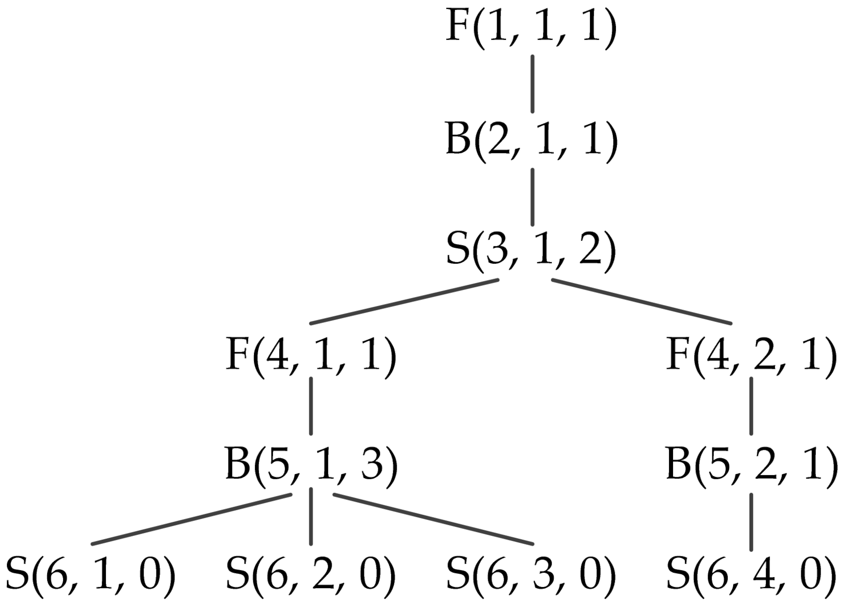
2.2. Multi-Layer FBS Vertical Decomposition of Customer Requirement-Product Function

In adaptive modification of a mechanical product, the specific structural units corresponding to all functional elements in the extension adaptive modification function module need to be defined, so it is needed to further use the multi-layer FBS vertical decomposition method for the product on the basis of original FBS overall division; thus, to obtain function-structure mapping units. In this paper, on the basis of the above delimiting of three function domains, a product function-structure vertical multi-layer mapping model was constructed by extending single-layer FBS to multi-layer FBS based on the decomposition principles of function independence, behavior coexistence and structure independence, to realize the mapping of all functional elements in function domain to structural units, and to qualitatively and quantitatively express the decomposed elements of each layer with the expression form of basic-element in extension design [27]. The formalized description model for multi-layer FBS decomposition of product is as follows:
FBS = i = 1 , j = 1 m , n [ A F ( F ( 3 i 2 , j , k ) , C a f , V a f ) A B ( B ( 3 i 1 , r , t ) , C a b , V a b ) M S ( S ( 3 i , h , l ) , C m s , V m s ) ]
where AF is function affair-element, AB is behavior affair-element, and MS is structure matter-element. The expression of basic-element in each decomposed layer includes layer number, node number, and number of subnodes in next layer. For example, 3i−2, j, and k are the layer number, node number, and number of subnodes in next layer, respectively, of AF, and similarly for AB and MS.
Figure 3 shows the example of multi-layer FBS decomposition model. There were six layers in the example, based on the decomposition model, the upper-layer function F(1, 1, 1) was mapped into lower-layer structures S(6, 1, 0), S(6, 2, 0), S(6, 3, 0), S(6, 4, 0).

3. Analysis of Product Function-Structure Correlation

A product can be regarded as an assembly composed of multiple components and mechanisms, and it executes related behaviors through its internal structure, to realize related functions and further to satisfy customer functional requirements. Correlations run through the real object layer and abstract layer of the product, and the product can be divided into three dimensions, i.e., structure-structure correlation, structure-function correlation, and function-function correlation. In addition, the function-function correlation is transformed into structure-structure correlation in the bottom layer. Through comprehensive consideration, the correlations for various elements can be summarized as integrated correlation conduction with the structure-structure correlation as the base and the structure-function correlation as feedback. Therefore, the discussion in this section focuses on the structure-structure correlation and the structure-function correlation.

3.1. Analysis of Structure-Structure Correlation

In order to realize quantitative expression and study of product structure layer correlation, a correlation network was constructed first with the feature matter-element packages as the nodes of correlation network of product, and the types of relationship between adjacent nodes were expressed with set R in detail. On this basis, a feature matter-element correlation matrix was further constructed, as shown in Figure 4, where Mi denotes the matter-element for the i-th feature.
In Figure 4, the first row and first column give feature matter-elements (M) and the other parts give a relationship matrix (A). The feature matter-elements are four types of geometric feature matter-element packages after breakdown of product parts, and the specific types and expression forms have been given in detail in reference [42]. The relationship matrix is mainly used to record the correlation relationship between any two feature matter-elements in the first row and first column of the feature matter-element correlation matrix. If the elements of the set R of relationship between two feature matter-elements are taken as relationship units r, the correlation relationship of two feature matter-elements relative to a relationship unit can be expressed with value 1 or 0 to denotes true or false relationship. For example, M1 and M2 constitute a relationship matrix R12, and R12 = {r1, r2, r3}. If M1 and M2 correlate relative to r1 and r2, then A12 = [0,1,1] and it is recorded in the matrix.

3.2. Analysis of Structure-Function Correlation

Structure is real object mapping of function. It can be discerned from correlation that the adaptive modification of structure layer may cause change of function layer, so a product structure behavior function reverse conduction model (SBF model) needs to be constructed based on the multi-layer FBS vertical decomposition model, to realize mechanism of reverse conduction from structure layer to function layer. The related feedback conduction steps from structure to function in the SBF model are illustrated in Figure 5, and each step is described as follows:
Step 1: Modification of product structure layer. Select a prior modification trigger unit from the parts in the function domains V+ and V of product based on the affair-element implication reasoning and implement modification operation for the feature structure of the trigger unit.
Step 2: Structure-behavior conduction. The modification of structure layer itself may not influence the behavior layer. When the product is needed to realize corresponding function, the difference of structure layer before and after modification is conducted to the behavior layer.
Step 3: Change of behavior layer. When such changes as increase, substitution, and decrease, occur in the original structure layer owing to transformation operation, such changes as behavior increase, behavior parameter value change, and behavior decrease, may also occur in the corresponding behavior layer, and the change of behavior child layer is fed back first to the behavior parent layer and finally to the target function layer.
Step 4: Behavior-function conduction. The change effect of behavior layer is conducted to the target function layer so that quantitative change effect and qualitative change effect occur in the target function layer.
Step 5: Change of product function layer. For the function elements in the function domains V+ and V, the quantitative change effect and qualitative change effect of function are realized under the conduction of behavior change effect. For the function elements in the V++, the function intensity generally remains unchanged due to the principle of structure independence followed in the early decomposition.
Step 6: Product function-customer requirement matching. Re-match the function parameter value corresponding to product function with that corresponding to the customer required function, to judge whether the condition that the dependent function value k ≥ 1 is tenable. If yes, it indicates that the product function satisfies the actual customer requirement, and the modification of structure layer is stopped. If not, further modification of structure layer is needed till the judgment condition is tenable based on the feedback from the SBF model.

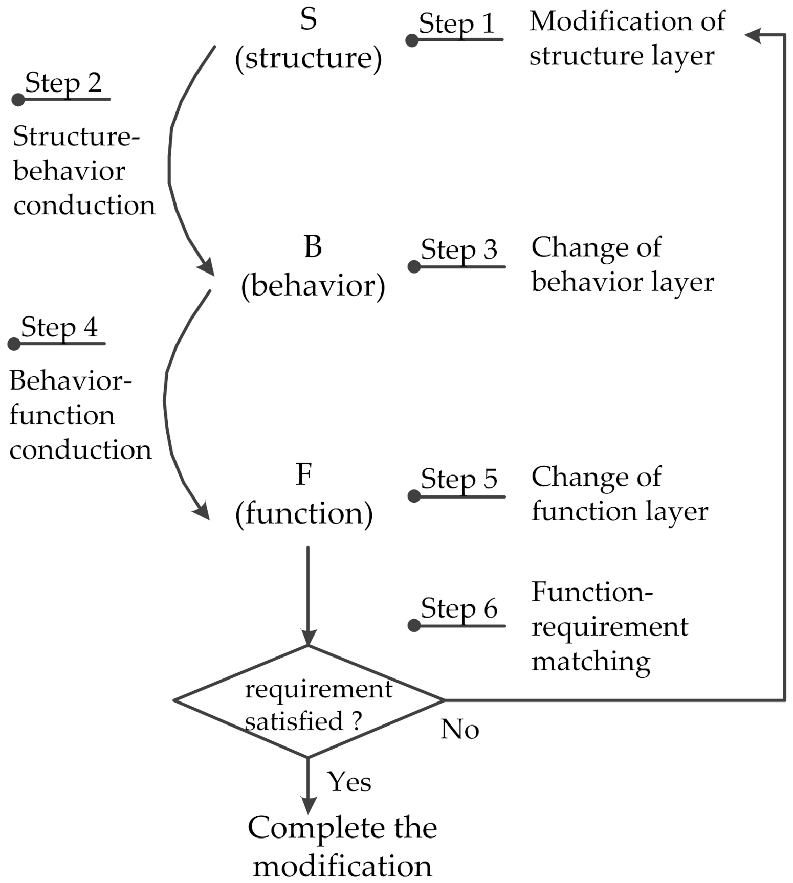
4. Conduction Transformation-Based Coordination for Product Structure Modification

4.1. Creation of Extension Transformation Operation

The contradiction between product function and customer required function is essentially a contradiction between function and structure of product, which can be coordinated through transformation on the internal structure of product. Transformation operations (T) were introduced as modification operation tools, and they were divided into seven types, i.e., substitution transformation operations (TS), increase transformation operation (TI), decrease transformation operation (TD), enlargement transformation operation (TE), reduction transformation operation (TR), copy transformation operation (TC), and identity transformation operation (TY), and the decomposition of T is as follows:
T = {TS, TI, TD, TE, TR, TC, TY}
For any transformation operation TQT, the transformation operation implemented on a node of correlation network can be expressed as:
A T ( v c O ) = T c 1 v 1 c 2 v 2 c 3 v 3 = T r a n s f o r m a t i o n   o p e r a t i o n D o m i n a t e d   o b j e c t v 1 A c t i n g   o b j e c t v 2 T r a n s f o r m a t i o n   d e g r e e v 3
The transformation operations are recorded in the form of affair-element, and then saved, to facilitate the later creation of transformation scheme.
As shown in Table 1, the actual transformation operations on feature matter-element by T can be divided into three types—value transformation, object transformation, and attribute transformation. The scope is restricted in selection of transformation operations for every transformation object so as to raise the selection efficiency. Value transformation corresponds to three transformation operations, for example, T(v) = TQ(v), and here TQ ∈ {TE, TR, TY}. Transformation step length l should be set for value transformation based on the actual problem. When transformation operations are implemented for geometric feature matter-element of part, the “easy or simple first” principle should be followed, so the priority sequence of the three transformation objects are as follows: T(v) > T(c) > T(O).

4.2. Extraction of Conduction Transformation Trigger Unit

Product modification design can be regarded as finding a solution to design contradiction problem. In order to raise production modification design efficiency, the contradiction between product function and customer requirement needs to be analyzed, to extract product core modification unit, i.e., conduction trigger unit (CTU). Affair-element implication analysis was introduced as a tool to extract CTU in the product. A core trigger part was determined first through affair-element implication analysis, and then the core trigger part was analyzed further, to extract core trigger feature of part.
The affair-element implication analysis reasoning can be expressed as:
i   =   1 ,   j   =   1 m , n A i j A i   =   1 ,   j   =   1 m , n A i j A ( i   =   1 ,   k   =   1 m , n A i k ) ( i   =   1 ,   l   =   1 m , s A i l ) A
where “∧” denotes “and” operation, “∨” denotes “or” operation, i is the layer number, and j is the affair-element number in one layer. The affair-elements are divided into lower-level affair-element, which is the “cause”, and upper-level affair-element, which is the “effect”. The occurrence of lower-level affair-element results in that of upper-level affair-element, in other words, the lower-level affair-element implies the upper-level affair-element.
With the contradiction problem in the initial upper-level affair-element being taken as the initial contradiction problem, the conflict resolution for upper-level affair-element can be realized by that for lower-level affair-element, and the conflict resolution for initial upper-level affair-element can be realized by that for bottom-layer affair-element. Therefore, the product structure involved in the bottom-layer affair-element can be extracted, to obtain CTU.

4.3. Judgment of Conduction Transformation Trigger Condition

In product adaptive modification design, modification of a structure in the product sometimes does not cause conduction transformation. Only if the conduction transformation trigger condition is met, linkage conduction may occur. Therefore, the conduction trigger condition needs to be analyzed and judged, to make clear when and where conduction transformation may occur in product modification design. Based on the actual modification situations, the conduction trigger in product modification design is formally expressed as follows:
T a c t i   =   1 n ( C T U i ) { C D U k } { R j } δ ( δ > 0 ) { T C a s e } { T a c t } { T 1 a c t , T 2 1 , T 3 2 , , T n n 1 }
In Equation (4), the conduction trigger occurrence condition is divided into four parts, namely, conduction trigger unit (CTU), conduction driven unit (CDU), correlation relationship {Rj}, and trigger threshold δ (δ > 0), and the conduction transformation is divided into two parts—active transformation Tact, and driven transformation iTj.
Conduction effect (CE) is introduced as a quantitative analysis indicator for transformation. Based on the form of conduction transformation, the effect change generated by conduction transformation is divided into structure-structure conduction transformation effect (CES-S), and structure-function conduction transformation effect (CES-F).
(1)
Structure-structure conduction transformation effect
For product case P to be modified, if the part set of the smallest assembly unit is Part = {Parti | i = 1, 2, 3, …, m}, and the part feature set is Partj = {Mj | j = 1, 2, 3, …, n}, where Mj = (O0, c0, v0), Mi = (O1, c1, v1), and there is active transformation Tact, where TactT, Tact(Mj) = (Mj, Mj) for Mj in MjMi so that (Tact)T1(Mi) = (Mi, Mi), T1T, then it indicates that the active transformation Tact of matter-element Mj causes the conduction transformation of matter-element Mi, the transformation object can be any element in L(O, c, v), the active transformation effect is ATES-S = L(Mj) − L(Mj), and the conduction transformation effect is:
C E S S = L ( M i ) L ( M i )
For multiple correlated geometric feature matter-elements M of part, the conduction transformation caused by one active transformation is:
T a c t ( M 0 , M 0 ) = { T i i 1 | T a c t = ( M 0 , M 0 ) , T 1 a c t = ( M 1 , M 1 ) , T 2 1 = ( M 2 , M 2 ) , , T n 1 n 2 = ( M n 1 , M n 1 ) T n n 1 = ( M n , M n ) , i = 1 , 2 , 3 , , n }
The conduction transformation operation is extracted from the above equation, to obtain the structure-structure driven transformation set {actT1, 1T2, 2T3,…, n−1Tn} caused by the active transformation Tact, thus to acquire a conduction transformation set {Tact}∧{actT1, 1T2, 2T3,…, n−1Tn}, which can be taken as the reference solution of modification in the actual product modification.
(2)
Structure-function conduction transformation effect
Based on the correlation between structure and function, when adaptive modification design is conducted for product structure layer, the related target function intensity will also be changed. Behavior layer is a transition layer, and the resultant effect change of behavior represents the target function intensity change caused by the change of structure layer and its conduction transformation:
T a c t ( M , M ) { T a c t } ( M , M ) E F ( B ) = j = 1 m k = 1 n B j k F P ( F i )
where, EF(B) denotes the resultant effect of behavior, and j denotes the layer number of behaviors, and the k is behavior number in the same layer.
Based on the above expression, the structure-function conduction transformation effect can be expressed with the difference in function parameter FP before and after transformation, that is,
C E S F = F P ( F i ) F P ( F i )
CES-S and CES-F are calculated from two dimensions, based on the correlation network and the SBF conduction mechanism, i.e., structure-structure conduction, structure-function conduction. Positive and negative conduction transformation effects are judged through the signs of CES-S and CES-F based on the actual modification situations. The transformation operations with positive conduction transformation effect should be extracted and saved, for reference by later designers in formulating product modification schemes.
Through summarization of the above analysis, the conduction transformation judgment steps are as follows:
Step 1: Determine CTU, and implement active transformation Tact;
Step 2: Judge whether the CTU has corresponding CDU based on the correlation network; if yes, go to step 3; otherwise, the conduction transformation occurrence condition is insufficient, go to step 5;
Step 3: Define the type of CTU-CDU correlation relationship, and determine the constraint relationship for occurrence of conduction transformation;
Step 4: Calculate the value of conduction transformation effect (CE) of CDU. If CE > δ, conduction transformation will occur; otherwise, the conduction transformation occurrence condition is insufficient, go to step 5;
Step 5: End.

4.4. Creation of Conduction Transformation-Based Coordination Strategy

The realization of qualitative change and quantitative change effects of product function through modification of structure layer requires transformation operations on the nodes of correlation network. Multiple transformation operations may be involved in the actual transformation, and a single transformation operation on one node may also relate to multiple transformation operations. The summarized transformation operation process can be expressed with the following matrix:
T M i = t i j m × n = t 11 t 12 t 1 n t 21 t 22 t 2 n t m 1 t m 2 t m n m   ×   n
In the matrix, Mi denotes the feature nodes in correlation network, and the transformation operation of Mi can be recorded as m × n dimension transformation operation matrix; tij is any one or more transformation operations, if it is identity transformation operation TY, the corresponding element in the matrix can be directly set to 0; the column number n for number of dimensions denotes the sequence of implemented transformation operations, and the row number m denotes the number of operation in single transformation operation.
The above transformation operation matrix is defined as active transformation Tact. Transformation operation of CTU is implemented through Tact, and the structure-structure conduction transformation and structure-function conduction transformation caused by Tact are recorded. The matching degree (MD) between product function and customer required function is judged through k(Epro-func) with the structure-structure conduction transformation set as modification implementation strategy and the structure-function conduction transformation as the feedback to structure modification. The structure-structure conduction transformation set {Tact}∧{actT1, 1T2, 2T3,…, n−1Tn} is extracted as modification strategy with MD ≥ 1 as the feasible resolution output condition. The specific operation of each transformation operation is expressed in the form of affair-element, and it is used as the strategic guidance for actual modification.

5. A Case Study

Cutting machines are commonly used processing equipment in clothing and leather manufacturing industries, and their working efficiency and reliability are crucial to corporate earnings. The working flow of an existing cutting machine mainly includes five processes, i.e., “Feed → Adsorb → Cut → Release pressure → Move out of window”, the schematic diagram of working is shown in Figure 6, and the specific processes are shown in Table 2. The adsorbing process is the optimal mode for cloth fixing, it primarily uses air-powered equipment to adjust the air pressure in the cavity. The current operation processes are independent and time sequenced, and the following operation can be conducted only after the previous operation is completed, so there are time intervals between processes, which influence the working efficiency. Now the proposed method is verified with the modification design of the delivery system of cutting machine as an example.

5.1. Customer Requirement-Product Function Mapping

There are customer requirements—CRs = {01-Moderate price; 02-Automatically material loading and unloading; 03-Low working noise; 04-High cutting efficiency; 05-Less waste produced from cutting; 06-Low energy consumption; 07-Simple equipment operation}. The requirements were categorized as follows:
(1)
FRs = {FR1 = <Automatically material loading and unloading>; FR2 = <Low working noise>; FR3 = <High cutting efficiency>; FR4 = <Less waste produced from cutting>; FR5 = <Low energy consumption>}
(2)
NFRs = {NFR1 = <Moderate price>; NFR2 = <Simple equipment operation>}
The above FRs were further expressed through function extraction and functional parameters as follows:
FRs = {FR1 = <Ft1-Deliver cloth, FP1-1-Material loading speed, FP1–2-Material unloading speed>; FR2 = <Ft2-Reduce noise, FP2-Noise reduction amount>; FR3 = <Ft3-Cut cloth, FP3-Cutting speed>; FR4 = <Ft4-Arrange cloth pattern, FP4-Ratio of surplus material>; FR5 = <Ft5-Reduce energy consumption, FP5-Energy consumption cost>}.
For three items {FRi | i = 2, 4, 5}, the relevant functions had been realized by setting up a sound-damping device, automatically optimizing arrangement of cloth pattern with PC, and evacuating air with variable-frequency vacuum pump, and the equipment could well satisfy the customer requirements in actual working. The {FRi | i = 1, 3} were closely correlated with the improvement of working efficiency of the product, and the customer requirement for actual working efficiency of equipment coincided with the requirement of the enterprise for modification design of cutting equipment in the current stage, so FR1 and FR3 were extracted as the target functional requirements.
The functions Ft1-Deliver cloth and Ft3-Cut cloth, originally realized independently, were combined together through function analysis. In other words, the working mode was changed to “Spread material → Cut → Move out of window”, to realize the function “cut material running through window” of cutting machine, that is, “cutting while moving”. Consequently, the FR1 and FR3 could be converted into the functional requirement FR = <Cut material running through window>. However, if the function “cut material running through window” was realized in actual cutting equipment by directly changing the working mode, there would be a hidden danger of transmission chain fracture.
The function parameter of “cut material running through window”, that is, FP-Cutting speed, was extracted with the cutting machine with changed working mode as research object, based on the target functional requirement. The summary of dependent function values as shown in Table 3 was obtained using the elementary dependent function calculation method in reference [27]. The FtV+ could be obtained with the calculated dependent function value k(FP) ∈ [0, 1) and the function domains, so modification of structure layer was needed.

5.2. Analysis of Structure Layer of Product

The Ft was decomposed into two parts, i.e., Ft1, and Ft3. It could be obtained based on the component modules of cutting machine that the Ft3 was mainly independently controlled by the moving component of cutting head, which was not influenced after the working mode was changed, but there was hidden danger of transmission chain fracture in the delivery system due to the working mode of “cut material running through window”. Therefore, the Ft1 was extracted as the core function item in initial decomposition. The multi-layer FBS decomposition of the delivery system is shown in Figure 7. The following parts of the delivery system of cutting machine could be obtained from the structure layer: 01-Bristle brick support plate, 02-Upper slide rail, 03-Lower slide rail, 04-Main beam, 05-Brick, 06-Motor, 07-Driving shaft, 08-Flange bearing, 09-Driven shaft, 10-Sprocket, 11-Chain.
The above parts were partially reduced to obtain the assembling parts of the product function body, namely, 01-Bristle brick support plate, 02-Upper slide rail, 03-Lower slide rail, 04-Main beam, 07-Driving shaft, 09-Driven shaft, 10-Sprocket, 11-Chain. The corresponding matter-element models are, respectively: M1, M2, M3, M4, M7, M9, M10, M11.
The feature matter-element package units of all parts were constructed as follows:
M1 = {M1-1(Bristle brick mounting hole), M1-2(Plate body mounting hole), M1-3(Plate body)};
M2 = {M2-1(Square through hole), M2-2(Rail body), M2-3(Mounting hole)};
M3 = {M3-1(Square through hole), M3-2(Rail body), M3-3(Mounting hole)};
M4 = {M4-1(Beam body)};
M7 = {M7-1(Power transmission sprocket section), M7-2(Bearing section), M7-3(Sprocket section), M7-4(Intermediate section), M7-5(Sprocket section), M7-6(Bearing section)};
M9 = {M9-1(Bearing section), M9-2(Sprocket section), M9-3(Intermediate section), M9-4(Sprocket section), M9-5(Bearing section)};
M10 = {M10-1(Mounting hole), M10-2(Sprocket body)};
M11 = {M11-1(Chain body)}.
A correlation network (Figure 8) was constructed with the feature matter-element packages of the above parts as nodes. A feature matter-element relationship set was constructed by extracting all feature matter-element nodes in Figure 8:
R = {r1-Dimension relationship; r2-Fit relationship; r3-Position relationship; r4-Transmission relationship; r5-Boolean relationship; r6-Connection relationship}.
The values of 6 types of correlation relationships between all feature matter-element nodes were recorded in a matter-element correlation matrix of delivery system of cutting machine, as shown in Table 4, which clearly described the dimension relationship, fit relationship, position relationship, transmission relationship, Boolean relationship, and connection relationship between feature matter-element nodes.

5.3. Creation of Conduction Transformation-Based Coordination Strategy for Structure Layer of Product

With the correlation analysis as the basis for implementation of conduction transformation-based coordination for the internal structure of delivery system of cutting machine, it can be discerned from further affair-element implication reasoning (shown in Figure 9) that, the occurrence of the initial upper-level affair-element A1-1 was triggered by lowermost-level affair-elements A5-1 and A4-2. The affair-element A5-1 was extracted and analyzed. The cloth was fixed to the bristle brick working table under the adsorption by the negative pressure in the vacuum cavity, and the larger the negative pressure in the vacuum cavity was, the larger the positive pressure N acted on the bristle brick support plate would be. Therefore, the affair-element A4-1 was triggered, and the “and” effect of the affair-element A4-2 was superposed. When f = uN > FLimit (f is the contact friction force between bristle brick support plate and upper slide rail, u is friction coefficient, and FLimit is the ultimate limit tension force the chain can withstand), the occurrence of A1-1 was finally caused.
Based on the above affair-element implication reasoning, reducing the contact friction force f was taken as the fundamental solution to the contradiction problem in the delivery system, and the dominated objects in the lower-level affair elements were extracted as conduction trigger units, i.e., CTU = {ctu1 = Bristle brick support plate, ctu2 = Upper slide rail}, where both ctu1 and ctu2 were components of delivery system, as shown in Figure 10.
The specific modification operations were implemented on ctu1 and ctu2 as below:
Tact was implemented on the extracted ctu1 as follows:
T c t u 1 = { T M i | M i = M 1 3 } T ( O ) = T I T Y 2 × 1 = T I 0 2 × 1
All transformation operations implemented on ctu1 in the above equation were transformed into an affair-element modification package unit as follows:
A T M 1 3 = T I c 1 v 1 c 2 v 2 c 3 v 3 c 4 v 4 = A d d D o m i n a t e d   o b j e c t P e r m a n e n t   m a g n e t A c t i n g   o b j e c t B r i s t l e   b r i c k   s u p p o r t   p l a t e M o u n t i n g   p o s i t i o n B o t t o m   o f   s u p p o r t   p l a t e S h a p e S e g m e n t e d   b a r s h a p e d
Tact was implemented on the extracted ctu2 as follows:
T c t u 2 = { T M i | M i = M 2 2 } = T I 1 T I 2 T I 3 T Y 4   ×   1 =   T I 1 T I 2 T I 3 0 4   ×   1
All transformation operations implemented on ctu2 in the above equation were transformed into an affair-element modification package unit as follows:
A T M 2 2 = A 1 = T I 1 c 1 v 1 c 2 v 2 c 3 v 3 c 4 v 4 = A d d D o m i n a t e d   o b j e c t R e c t a n g u l a r   t h r o u g h   h o l e   A c t i n g   o b j e c t B o t h   s i d e s   o f   u p p e r   s l i d e   r a i l   A r r a n g e m e n t S y m m e t r i c   o n   b o t h   s i d e s   D i m e n s i o n s 35 × 35 A 2 = T I 2 c 1 v 1 c 2 v 2 c 3 v 3 c 4 v 4 = A d d D o m i n a t e d   o b j e c t Teflon   slide   trip   A c t i n g   o b j e c t Top   of   upper   slide   rail   Quantity 10   Shape Bar shaped A 3 = T I 3 c 1 v 1 c 2 v 2 c 3 v 3 c 4 v 4 = A d d D o m i n a t e d   o b j e c t Electric   magnet   A c t i n g   o b j e c t Inside   of   upper   slide   rail   Components Silicone   steel   core   +   coil   Shape Pillar shaped
The above specific modification operation Tact was implemented on CTU = {ctui | i = 1, 2}, as shown in Figure 11. It can be obtained through analysis of structure-structure conduction transformation based on the correlation network and correlation matrix that, after Tact was implemented on M1-3 in ctu1 and M2-2 in ctu2, other feature matter-element trigger items connected with them were not triggered, in other words, there were no corresponding CDU, and the conduction trigger conditions were not satisfied. Therefore, the active transformation of structure layer did not cause conduction transformation of related feature matter-elements. Since the functional requirements were taken as modification drivers in this paper, it can be discerned from further analysis of structure-function conduction transformation based on the SBF reverse conduction model that, after modification transformation was implemented on ctu1 and ctu2, there was negative pressure formed in the vacuum cavity of cutting machine under the air evacuation effect of vacuum pump, and the cloth on the surface of bristle brick closely attached to the bristle brick under the effect of atmospheric pressure. There was an electromagnetic force generated in the reverse direction of the positive pressure on the bristle brick support plate under the principle of repulsion between the identical poles of two magnets, which reduced the contact friction force between the bristle brick support plate and upper slide rail of the delivery system, causing the delivery system to realize the function of delivery through window.
Simplified model construction and simulation was conducted for the delivery system assembly after adaptive modification (Figure 12). With the cloth stacking thickness h = 30 mm, the negative pressure of vacuum cavity P = 22,000 Pa and the size of vacuum cavity (length a = 2900 mm, width b = 2050 mm, height c = 900 mm) as an example, it was obtained that σmax = 7 MPa at the maximum stress place of the simplified model, far less than the yield stress of the chain, indicating that this modification-based coordination scheme was feasible.
The following was extracted by summarizing the above conduction transformation-based coordination strategy:
{ T C a s e } = { T c t u 1 } = { T I , T Y } { T Y } { T c t u 2 } = { T I 1 , T I 2 , T I 3 , T Y } { T Y }
It can be found through comparison with the structure of the original delivery system assembly in Figure 10 that the delivery system assembly (Figure 11) improved using the transformation-based coordination method proposed in this paper well reused the original structure with small degree of change to the original assembly structure, achieving modification-based coordination for the structure layer of product with low cost, thus to satisfy the functional requirements.
Figure 11. Adaptive modification of components of delivery system.
Applsci 11 11757 g011
Figure 12. Simplified model simulation of improved components of delivery system.
Applsci 11 11757 g012
This research work focused on the contradictions solving in adaptive design driven by functional requirements, including construction of customer requirement-product function matching mechanism, analysis of product function-structure correlation, and conduction transformation-based coordination for structure modification.
In the case study, with the goal of improving cutting efficiency of cutting machine, the process of generating the design scheme under the new demand of the user was discussed in detail. Functional requirements FR1 = <Automatically material loading and unloading>, FR3 = <High cutting efficiency>, related to the work efficiency of the cutting machine, were extracted, and then they were converted into FR = <cut material running through window>. However, there was the design contradiction, although the FR was satisfied, it would cause the fracture of the transmission chain. Structure layer analysis for the delivery system of cutting machine was conducted to build the multi-layer FBS model, structure correlation network, and correlation matrix.
Based on the affair-element implication reasoning of transmission chain fracture problem, an effective way to avoid the fracture problem was to reduce the friction force between the bristle brick support plate and the upper slide rail. Thus, conduction trigger units ctu1 = bristle brick support plate, ctu2 = upper slide rail, were extracted; implementing the extension transformation TI <add a permanent magnet> for ctu1, and the extension transformation TI1 <add the rectangular through hole>, TI2 <add the Teflon slide stripe>, TI3 <add the electric magnet> for ctu2, to generate the design scheme, where the magnetic force could help reduce the pressure of the upper slide rail, thereby reducing the friction force between the upper slide rail and the bristle brick support plate.
Therefore, the proposed method of this research work was used to solve the contradictory problem arising from the newly added functional requirement <cut material running through window> of the cutting machine, and the innovative design scheme was successfully generated to verify the feasibility of the method.

6. Discussion

In this paper, an effective conduction transformation-based coordination method was proposed to solve the design conflict in product adaptive design. A case study concerning the realization of new function for the cutting machine was conducted to verify the feasibility of the proposed method; and the theoretical and practical implications of this research work are discussed below.
Adaptive design is an incremental innovative method, which generates new product design schemes that meet the requirements by modifying part of the functions, principles, and structures of existing products, and fully reuses the existing design, manufacturing, and management resources to reduce product development time and cost [43]. However, in actual adaptive modification process, the complex interacted correlation between structural modules and the complex mapping relationship between structure and function lead to the general conduction transformation problem, namely, when a certain structural parameter is modified, the related structural parameters and functional performance will change accordingly, and the resulting conduction problem may be beneficial or harmful. Therefore, it is necessary to clarify the mapping relationship between function and structure, and the interacted correlation among structures, and find the appropriate active transformation structure, that is, the conduction trigger element. This paper established a multi-layer function-behavior-structure vertical decomposition model for the requirement function, constructed a structure-structure correlation analysis model, and proposed a structure-function mapping analysis method based on the SBF feedback model. In the adaptive modification of delivery system of cutting machine for realizing the function of cutting while moving, the core function Ft1-Deliver cloth was decomposed into multi-layer FBS model, which helped to clarify the mapping relationship between functions and structures. For instance, the bristle brick support plates, upper and lower slide rails, main beams, and bristle bricks together constituted a module to achieve the function of laying fabrics on the cutting machine workbench. The correlation network and correlation matrix of structures of delivery system were constructed, and the bristle brick support plate and the upper slide rail were extracted as conduction transformation trigger elements based on the implication analysis.
Based on the correlation analysis of structural modules, the potential conduction transformation could be clearly discovered when conducting the active transformation for the trigger element, and then the conduction transformation scheme with minimal conduction effect could be found to generate the coordination strategy composed of transformation operations for the design contradiction. The design contradiction in adaptive modification for the cutting machine was that when realizing the cutting and moving function, the transmission chain of the delivery system was easy to break. For the trigger element bristle brick support plate, the active transformation, adding the permanent magnet, was conducted; for the trigger element upper slide rail, the active transformations, adding the rectangular through hole, Teflon slide strip, and electric magnet, were performed. Thus, the active transformations and conduction transformations were extracted to generate the coordination strategy. However, this paper did not discuss how to obtain an electromagnetic principle, namely the inspiration of innovative principle was not elaborated, but focused on structure-structure, structure-function correlation analysis, and extracted the coordination strategy through the innovative solution. In this study, we adopted the Extenics to achieve conceptual scheme to solve the contradictory problem with extensible and conjugate analysis. In addition, there are other useful innovative design methods, such as the theory of inventive problems solving (TRIZ, a Russian acronym) [44], constraint satisfaction problem (CSP) [45], case-based reasoning (CBR) [46].
This paper adopted the basic-element model in Extenics to formally describe transformation operations. For example, the transformation operation that adding a permanent magnet in the bristle brick support plate was represented by the affair-element model, where transformation operation was the action of adding, the dominated object was the permanent magnet, the acting object was the bristle brick support plate, and the representation model also described that the mounting position was at the bottom of support plate, and shape of the permanent magnet was a segmented bar. The representation of transformation operations with basic-element model formed the coordination strategy to facilitate the reuse of design knowledge. At the same time, it is also the research basis for intelligent reasoning and decision-making of design contradictory problems solving.

7. Conclusions

In this paper, the product use functions and customer expected functional requirements were expressed with extension function domains, the customer requirement matching to product function mechanism was constructed with the extension dependent function, and a multi-layer function-behavior-structure mapping model of product was created. A feature matter-element correlation matrix was constructed with the feature matter-element packages as the nodes of correlation network of product, the correlation between basic-elements were expressed quantitatively at the “structure-structure” level; the reverse conduction mechanism from structure layer to function layer was formed by constructing a product structure behavior function reverse conduction model, and the correlation between structure and function was obtained further at the “structure-function” level. With transformation operations introduced as modification operation tool, and the nodes of correlation network taken as implementation objects, a conduction transformation-based coordination strategy was formed by extracting conduction trigger units, clarifying conduction trigger condition, and implementing transformation operations to generate design scheme for product adaptive modification.
In our study, the conduction transformation path with the minimal conduction effect is obtained through manual analysis, so as to extract the coordination strategy for the design contradiction. However, the correlation analysis between structural modules, structure and function depends on the experience of designers, and the efficiency is not high. For further research, the machine learning algorithms will be adopted to realize acquisition of structure-structure and structure-function explicit correlation rules and exploration of implicit correlation rules, and we will make more efforts to analyze the conduction mechanism for intelligent adaptive modification of products.

Author Contributions

Conceptualization, J.Z. and Z.X.; methodology, J.Z., Z.X., S.R. and Y.Z.; validation, J.Z., Z.X. and D.Y.; formal analysis, M.Z.; investigation, M.Z.; resources, Y.Z.; data curation, D.Y. and M.Z.; writing—original draft preparation, J.Z. and Z.X.; writing—review and editing, Y.Z. and J.Z.; supervision, Y.Z.; project administration, S.R. All authors have read and agreed to the published version of the manuscript.

Funding

This research was supported by the National Natural Science Foundation of China (grant number. 51875524, 52005444) and the Zhejiang Basic Public Welfare Research Plan Projects (grant number. LGG19F020005) funded by the Science Technology Department of Zhejiang Province, China.

Institutional Review Board Statement

Not applicable.

Informed Consent Statement

Not applicable.

Data Availability Statement

Not applicable.

Acknowledgments

This work was supported by the National Natural Science Foundation of China [grant numbers 51875524, 52005444] and the Zhejiang Basic Public Welfare Research Plan Projects [grant number LGG19F020005].

Conflicts of Interest

The authors declare no conflict of interest.

References

  1. Stone, R.B.; Wood, K.L. Development of a functional basis for design. J. Mech. Des. 2000, 122, 359–370. [Google Scholar] [CrossRef]
  2. Gu, P.; Hashemian, M.; Nee, A.Y.C. Adaptable design. CIRP Ann.–Manuf. Technol. 2004, 53, 539–557. [Google Scholar] [CrossRef]
  3. Xue, D.; Nee, A.Y.C. Adaptable design: Concepts, methods, and applications. Proc. Inst. Mech. Eng. Part B J. Eng. Manuf. 2009, 223, 1367–1387. [Google Scholar]
  4. Pahl, G.; Beitz, W. Engineering Design: A Systematic Approach; Springer: London, UK, 1996. [Google Scholar]
  5. Opran, C.G.; Pricop, M.; Teodorru, C. Research regarding adaptive design of gear pumps used for polymeric products engineering. Appl. Mech. Mater. 2015, 760, 601–606. [Google Scholar] [CrossRef]
  6. Wan, Y.J.; Li, Y.; Li, W.Q.; Yan, X.Q. Method and realization for product innovative design based on endogenous function requirements. Comput. Integ. Manuf. Syst. 2013, 19, 235–243. [Google Scholar]
  7. Liang, R.; Zhang, J.H.; Tan, R.H.; Li, Y. Design process model and application of the existing product function innovation. J. Mech. Eng. 2016, 52, 50–61. [Google Scholar] [CrossRef]
  8. Morris, A.; Halpern, M.; Setchi, R.; Prickett, P. Assessing the challenges of managing product design change through-life. J. Eng. Des. 2015, 27, 25–49. [Google Scholar] [CrossRef] [Green Version]
  9. Jarratt, T.A.W.; Eckert, C.M.; Caldwell, N.H.M.; Clarkson, P.J. Engineering change: An overview and perspective on the literature. Res. Eng. Des. 2010, 22, 103–124. [Google Scholar] [CrossRef]
  10. Ullah, I.; Tang, D.B.; Yin, L.L.; Hussain, I.; Wang, Q. Cost-effective propagation paths for multiple change requirements in the product design. Proc. Inst. Mech. Eng. C-J. Mech. 2018, 232, 1572–1585. [Google Scholar] [CrossRef]
  11. Li, Y.; Zhao, W.; Tong, S. Simulation based scheduling of multiple change propagations in multistage product development processes. Expert Syst. Appl. 2017, 89, 1–19. [Google Scholar] [CrossRef]
  12. Zhang, H.Z.; Ding, G.F.; Li, R.; Qin, S.F.; Yan, K.Y. Design change model for effective scheduling change propagation paths. Chin. J. Mech. Eng. 2017, 30, 1081–1090. [Google Scholar] [CrossRef]
  13. Yang, F.; Duan, G.J. Developing a parameter linkage-based method for searching change propagation paths. Res. Eng. Des. 2011, 23, 353–372. [Google Scholar] [CrossRef]
  14. Tang, D.B.; Xu, R.H.; Tang, J.C.; He, R. Analysis of engineering change impacts based on design structure matrix. J. Mech. Eng. 2010, 46, 154–161. [Google Scholar] [CrossRef]
  15. You, C.F.; Yeh, S.C. Engineering change propagation system using STEP. Concurr. Eng.-Res. Appl. 2002, 10, 349–356. [Google Scholar] [CrossRef]
  16. Lee, J.; Hong, Y.S. Bayesian network approach to change propagation analysis. Res. Eng. Des. 2017, 28, 437–455. [Google Scholar] [CrossRef]
  17. Gong, Z.W.; Mo, R.; Yang, H.C.; Chen, T. Method for forecasting avalanche propagation of engineering change. Comput. Integr. Manuf. Syst. 2012, 18, 2619–2627. [Google Scholar]
  18. Masmoudi, M.; Leclaire, P.; Zolghadri, M.; Haddar, M. Change propagation prediction: A formal model for two-dimensional geometrical models of products. Concurr. Eng.-Res. Appl. 2017, 25, 174–189. [Google Scholar] [CrossRef]
  19. Hamraz, B.; Caldwell, N.H.M.; Clarkson, P.J. A Multidomain engineering change propagation model to support uncertainty reduction and risk management in design. J. Mech. Des. 2012, 134, 1–14. [Google Scholar] [CrossRef]
  20. Tavčar, J.; Duhovnik, J. Engineering change management in individual and mass production. Robot. Cim.-Int. Manuf. 2005, 21, 205–215. [Google Scholar] [CrossRef]
  21. Scholz-Reiter, B.; Hohns, H.; Kruse, A.; Konig, E. Hybrid product change management in the ramp-up phase of the automotive industry. Ind. Manag. 2004, 20, 21–24. [Google Scholar]
  22. Morris, A.; Setchi, R.; Prickett, P. Product change management and future information architectures. Smart. Innov. Syst. Tech. 2016, 52, 241–250. [Google Scholar]
  23. Koh, E.C.Y.; Caldwell, N.H.M.; Clarkson, P.J. A method to assess the effects of engineering change propagation. Res. Eng. Des. 2012, 23, 329–351. [Google Scholar] [CrossRef]
  24. Li, Y.L.; Lin, P.H. Parallel change propagation model of complex product. Comput. Integr. Manuf. Syst. 2017, 23, 737–743. [Google Scholar]
  25. Eisa, H.; Garstenauer, A.; Blackburn, T. Causes of engineering change propagation: An analysis during product lifecycle. Eng. Manag. J. 2018, 30, 3–13. [Google Scholar] [CrossRef]
  26. Eltaief, A.; Louhichi, B.; Remy, S. Associations management and change propagation in the CAD assembly. Comput. Ind. 2018, 98, 134–144. [Google Scholar] [CrossRef]
  27. Yang, C.Y.; Cai, W. Extenics: Theory, Method and Application; Science Press: Beijing, China, 2013. [Google Scholar]
  28. Tang, L.; Yang, C.Y.; Li, W.H. Adopting gene expression programming to generate extension strategies for incompatible problem. Neural. Comput. Appl. 2016, 28, 2649–2664. [Google Scholar] [CrossRef]
  29. Zhan, Y.W.; Su, N. Extension Design; Science Press: Beijing, China, 2010. [Google Scholar]
  30. Li, W.J.; Song, Z.H.; Mao, E.R.; Suh, S. Using Extenics to describe coupled solutions in Axiomatic design. J. Eng. Des. 2018, 30, 1–31. [Google Scholar] [CrossRef]
  31. Ren, S.D.; Gui, F.Z.; Zhao, Y.W.; Xie, Z.W.; Hong, H.H.; Wang, H.W. Accelerating preliminary low-carbon design for products by integrating TRIZ and Extenics methods. Adv. Mech. Eng. 2017, 9, 1–18. [Google Scholar] [CrossRef] [Green Version]
  32. Zhao, Y.W.; Hong, H.H.; Jiang, G.C.; Chen, W.G.; Wang, H.W. Conflict resolution for product performance requirements based on propagation analysis in the extension theory. Adv. Mech. Eng. 2014, 6, 1–17. [Google Scholar] [CrossRef] [Green Version]
  33. Zhou, J.Q.; Zhao, Y.W.; Hong, H.H.; Wang, H.; Chen, W.G. Coordination method of extension conductive transformation for performance conflict based on requirement- driven. Comput. Integr. Manuf. Syst. 2013, 19, 1205–1215. [Google Scholar]
  34. Zhou, J.Q.; Zhao, Y.W.; Hong, H.H.; Wang, H.; He, L. Conduction cooperation method for product performance conflicts based on extension transformation. Chin. Mech. Eng. 2014, 25, 661–668. [Google Scholar]
  35. Tang, L.; Yang, C.Y. Conductive transformation under complicated basic-element correlative network. CAAI Trans. Intell. Syst. 2016, 11, 104–110. [Google Scholar]
  36. Gong, J.Z.; Qiu, J.; Li, G.X.; Li, W. Extension approach for product module variant design. Comput. Integr. Manuf. Syst. 2008, 14, 1256–1267. [Google Scholar]
  37. Chandrasegaran, S.K.; Ramani, K.; Sriram, R.D.; Horvath, I.; Bernard, A.; Harik, R.F.; Gao, W. The evolution, challenges, and future of knowledge representation in product design systems. Comput.-Aided Des. 2013, 45, 204–228. [Google Scholar] [CrossRef]
  38. Gero, J.S.; Kannengiesser, U. The situated function-behaviour-structure framework. Des. Stud. 2004, 25, 373–391. [Google Scholar] [CrossRef]
  39. He, R.; Tang, D.B.; Xue, J.B. Engineering change propagation based on design structure matrix. Comput. Integr. Manuf. Syst. 2008, 14, 656–660. [Google Scholar]
  40. Chen, L.; Zheng, Y.; Xi, J.T.; Li, S.Y. An analysis method for change propagation based on product feature network. Res. Eng. Des. 2020, 31, 491–503. [Google Scholar] [CrossRef]
  41. Zhang, J.H.; Wang, F.L.; Wang, C.K. Integrating case-based with rule-based reasoning in body-in-white fixture design. Int. J. Adv. Manuf. Technol. 2016, 85, 1807–1824. [Google Scholar] [CrossRef]
  42. Xie, Z.W.; Zhao, Y.W.; Ren, S.D.; Gui, F.Z. Study on functional-requirement oriented recognition method of product adaptive modification unit. Comput. Integr. Manuf. Syst. 2020, 26, 426–436. [Google Scholar]
  43. Tomiyama, T.; Gu, P.; Jin, Y.; Lutters, D.; Kind, C.; Kimura, F. Design methodologies: Industrial and educational applications. CIRP Ann.-Manuf. Technol. 2009, 58, 543–565. [Google Scholar] [CrossRef] [Green Version]
  44. Chechurin, L.; Borgianni, Y. Understanding TRIZ through the review of top cited publications. Comput. Ind. 2016, 82, 119–134. [Google Scholar] [CrossRef]
  45. Popoff, A.; Millet, D. Sustainable life cycle design using constraint satisfaction problems and quality function deployment. Proc. CIRP 2017, 61, 75–80. [Google Scholar] [CrossRef]
  46. Roldan Reyes, E.; Negny, S.; Cortes Robles, G.; Le Lann, J.M. Improvement of online adaptation knowledge acquisition and reuse in case-based reasoning: Application to process engineering design. Eng. Appl. Artif. Intell. 2015, 41, 1–16. [Google Scholar] [CrossRef]
Figure 1. Hierarchical analysis of requirements.
Applsci 11 11757 g001
Figure 2. Flow of hierarchical analysis of requirements.
Applsci 11 11757 g002
Figure 3. Example of the multi-layer function-behavior-structure (FBS) decomposition model.
Applsci 11 11757 g003
Figure 4. Feature matter-element correlation matrix.
Applsci 11 11757 g004
Figure 5. The structure-behavior-function (SBF) feedback model.
Applsci 11 11757 g005
Figure 6. Schematic diagram of working of cutting machine.
Applsci 11 11757 g006
Figure 7. Multi-layer FBS decomposition of delivery system of cutting machine.
Applsci 11 11757 g007
Figure 8. Construction of correlation network for delivery system of cutting machine.
Applsci 11 11757 g008
Figure 9. Affair-element implication reasoning of transmission chain fracture problem.
Applsci 11 11757 g009
Figure 10. Components of delivery system.
Applsci 11 11757 g010
Table 1. Type of transformation operation.
Transformation Operation ObjectSymbol ExpressionSelected Transformation OperationsTransformation Priority
Value transformationT(v)TE, TR, TYI
Attribute transformationT(c)TC, TS, TYII
Object transformationT(O)TI, TD, TC, TS, TYIII
Table 2. Working processes of cutting machine.
No.ProcessMain Contents
0PrepareArrange material, e.g., cloth, or leather, with a spreading mechanism, to form a patch with height of ~100 mm, and place the patch onto the cutting table.
1FeedAllow the feeding system to operate; stop feeding after one end of the material to be cut is delivered to the place near the material outlet.
2Adsorb2.1 Cover film: Cover film onto the material to be cut so that the material is in relatively closed environment;
2.2 Depressurize (the cavity): Start the vacuum pump, to evacuate air from the cavity under the film, so that the cavity becomes low pressure environment, resulting in its inside-outside pressure difference, which makes the material to be cut adsorbed to the bristle bed.
3CutAllow the cutter control system to operate so that the material is cut into the required shape by the cutter according to the path preset in the sample arrangement system.
4Move out of window4.1 Raise pressure (in the cavity): After the material in the current window is cut, stop the cutting process, and reduce the air evacuating rate of the vacuum pump, so that the air pressure in the cavity rises slightly, making the material adsorbed to the bristle bed and easy to be moved.
4.2 Move material: Allow the feeding system to operate so that the cut cloth, etc. is delivered to the arranging table and the material to be cut is delivered to the cutting window. Next, repeat processes 1–4.
5EndAfter all materials are cut, turn off the system.
Table 3. Dependent function value calculation.
Functional ParameterIdeal Domain X0
(m/min)
Extended Domain X
(m/min)
Optimal Point x0
(m/min)
Actual Value x
(m/min)
Dependent Function Value k(x)
FP(40,50)(30,50)50350.5
Table 4. Matter-element correlation matrix of delivery system of cutting machine (partial data).
MM1-1M1-2M1-3M2-1M2-2M2-3M3-1M3-2M3-3M4-1M7-1M7-2
M1-1(0,0,0,
0,0,0)
(1,0,0,
0,1,0)
(0,0,0,
0,0,0)
(0,0,0
,0,0,0)
(0,0,0,
0,0,0)
(0,0,0,
0,0,0)
(0,0,0,
0,0,0)
(0,0,0,
0,0,0)
(0,0,0,
0,0,0)
(0,0,0,
0,0,0)
(0,0,0,
0,0,0)
M1-2(0,0,0,
0,0,0)
(1,0,0,
0,1,0)
(0,0,0,
0,0,0)
(0,0,0,
0,0,0)
(0,0,0,
0,0,0)
(0,0,0,
0,0,0)
(0,0,0,
0,0,0)
(0,0,0,
0,0,0)
(0,0,0,
0,0,0)
(0,0,0,
0,0,0)
(0,0,0,
0,0,0)
M1-3(1,0,0,0,1,0)(1,0,0,
0,1,0)
(0,0,0,
0,0,0)
(0,0,1,
0,0,0)
(0,0,0,
0,0,0)
(0,0,0,
0,0,0)
(0,0,0,
0,0,0)
(0,0,0,
0,0,0)
(0,0,0,
0,0,0)
(0,0,0,
0,0,0)
(0,0,0,
0,0,0)
M2-1(0,0,0,
0,0,0)
(0,0,0,
0,0,0)
(0,0,0,
0,0,0)
(1,0,0,
0,1,0)
(0,0,0,
0,0,0)
(0,0,0,
0,0,0)
(0,0,0,
0,0,0)
(0,0,0,
0,0,0)
(0,0,0,
0,0,0)
(0,0,0,
0,0,0)
(0,0,0,
0,0,0)
M2-2(0,0,0,
0,0,0)
(0,0,0,
0,0,0)
(0,0,1,
0,0,0)
(1,0,0,
0,1,0)
(1,0,0,
0,1,0)
(0,0,0,
0,0,0)
(0,0,0,
0,0,0)
(0,0,0,
0,0,0)
(0,0,0,
0,0,0)
(0,0,0,
0,0,0)
(0,0,0,
0,0,0)
M2-3(0,0,0,
0,0,0)
(0,0,0,
0,0,0)
(0,0,0,
0,0,0)
(0,0,0,
0,0,0)
(1,0,0,
0,1,0)
(0,0,0,
0,0,0)
(0,0,0,
0,0,0)
(0,0,0,
0,0,0)
(0,0,0,
0,0,0)
(0,0,0,
0,0,0)
(0,0,0,
0,0,0)
M3-1(0,0,0,
0,0,0)
(0,0,0,
0,0,0)
(0,0,0,
0,0,0)
(0,0,0,
0,0,0)
(0,0,0,
0,0,0)
(0,0,0,
0,0,0)
(1,0,0,
0,1,0)
(0,0,0,
0,0,0)
(0,0,0,
0,0,0)
(0,0,0,
0,0,0)
(0,0,0,
0,0,0)
M3-2(0,0,0,
0,0,0)
(0,0,0,
0,0,0)
(0,0,0,
0,0,0)
(0,0,0,
0,0,0)
(0,0,0,
0,0,0)
(0,0,0,
0,0,0)
(1,0,0,
0,1,0)
(1,0,0,
0,1,0)
(0,0,1,
0,0,1)
(0,0,0,
0,0,0)
(0,0,0,
0,0,0)
M3-3(0,0,0,
0,0,0)
(0,0,0,
0,0,0)
(0,0,0,
0,0,0)
(0,0,0,
0,0,0)
(0,0,0,
0,0,0)
(0,0,0,
0,0,0)
(0,0,0,
0,0,0)
(1,0,0,
0,1,0)
(0,0,0,
0,0,0)
(0,0,0,
0,0,0)
(0,0,0,
0,0,0)
M4-1(0,0,0,
0,0,0)
(0,0,0,
0,0,0)
(0,0,0,
0,0,0)
(0,0,0,
0,0,0)
(0,0,0,
0,0,0)
(0,0,0,
0,0,0)
(0,0,0,
0,0,0)
(0,0,1,
0,0,1)
(0,0,0,
0,0,0)
(0,0,0,
0,0,0)
(0,0,0,
0,0,0)
M7-1(0,0,0,
0,0,0)
(0,0,0,
0,0,0)
(0,0,0,
0,0,0)
(0,0,0,
0,0,0)
(0,0,0,
0,0,0)
(0,0,0,
0,0,0)
(0,0,0,
0,0,0)
(0,0,0,
0,0,0)
(0,0,0,
0,0,0)
(0,0,0,
0,0,0)
(1,0,1,
0,1,0)
M7-2(0,0,0,
0,0,0)
(0,0,0,
0,0,0)
(0,0,0,
0,0,0)
(0,0,0,
0,0,0)
(0,0,0,
0,0,0)
(0,0,0,
0,0,0)
(0,0,0,
0,0,0)
(0,0,0,
0,0,0)
(0,0,0,
0,0,0)
(0,0,0,
0,0,0)
(1,0,1,
0,1,0)
Publisher’s Note: MDPI stays neutral with regard to jurisdictional claims in published maps and institutional affiliations.

