1. Introduction
Rockfall constitutes one of the most hazardous landslide phenomena and can cause fatalities and damages [
1,
2,
3]. For this reason, preventive and protective structures are installed to reduce rockfall risk in inhabited areas. Among them, reinforced drapery meshes, subdivided into secured or pinned draperies, represent an effective solution for minimizing rockfall risk, especially for vertical rock faces overhanging road infrastructures [
4,
5]. The system consists of steel wire mesh panels and a systematic anchoring pattern, which directly acts on the stability of the rock surface [
6,
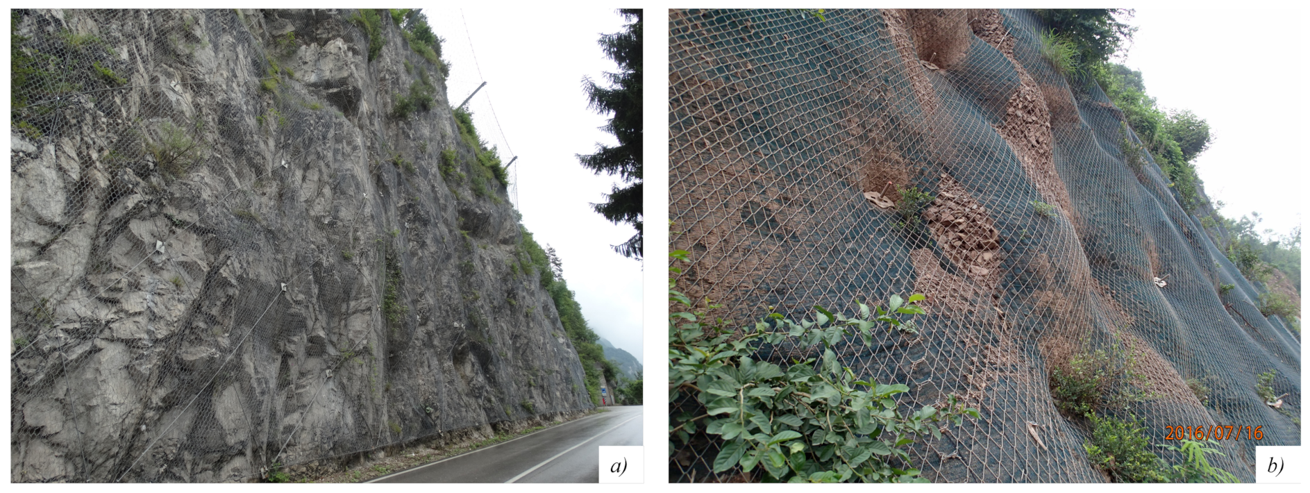
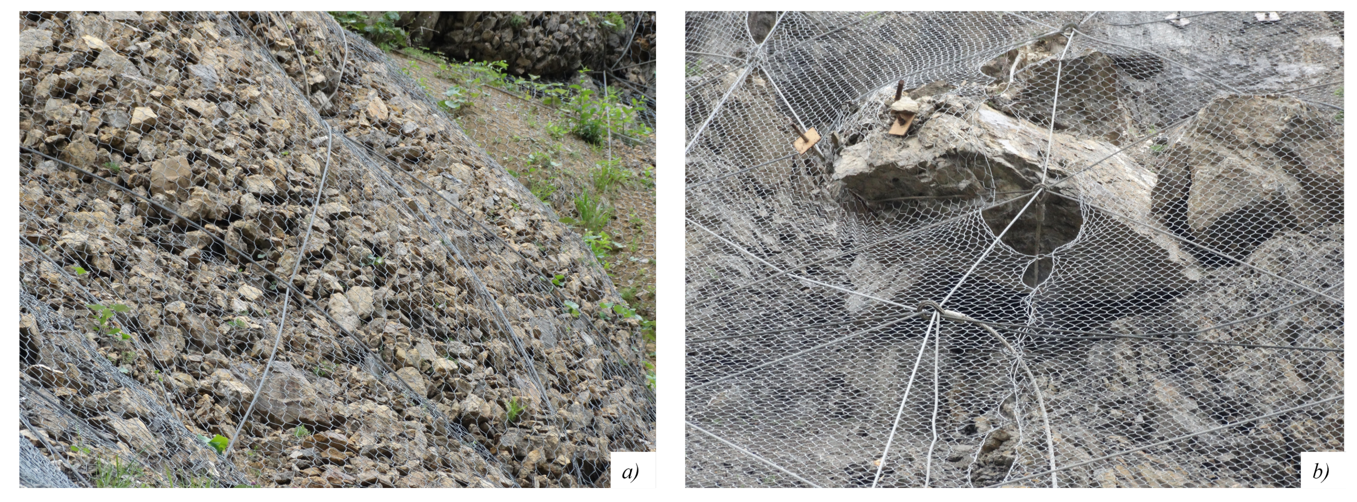
7]. In secured drapery, the anchors, whose pattern can be squared or quincunx-like, are connected to each other and to the net through ropes, forming a rhomboidal or square rope grid. The ropes are generally connected to the heads of the anchors, equipped with eyebolts or plates, proceeding from top to bottom, as seen in
Figure 1a. Alternatively, if no ropes are installed (pinned drapery systems), spike plates, which fasten the anchors and the mesh to the rock, are used, as shown in
Figure 1b. This structure is able to control the movement of rock blocks and fragments by confining small detached fragments into delimited sections of the mesh. The net can be made up of single-torsion or double-twisted steel wire mesh or of several types of fabric, such as a cable net, in which the cables are fixed to each other with studs or wire threads.
As a result of the increasing usage of this system due to its low cost and ease of installation, recent studies have aimed to investigate the most appropriate design method [
8,
9,
10], either with numerical methods [
11,
12,
13,
14] or with real-scale tests [
15,
16,
17,
18]. The scientific literature also includes numerical studies on the net component only [
19,
20,
21,
22].
Despite being widely used, no universally recognized guidelines or technical standards exist for the design of reinforced drapery systems [
15], and the mechanisms of preventive/protective rockfall mitigation measures are still debated today [
8]. As an example, Pol and Gabrieli [
14] subdivided reinforced drapery systems into two categories according to the scope: the prevention of the detachment of unstable single rock blocks, and the retention/stabilization of shallow portions of weathered rock or soil slopes. The former task is generally achieved by using rock bolts, i.e., a passive system; in the framework of the latter case, Cala et al. [
10] assumed that the system is active, i.e., that the mesh can exert pressure normal to the slope, and the anchors have an initial pretension.
Focusing on rock slopes, a different approach was proposed by Giacchetti et al. [
23]: the anchors, acting as a passive system, should prevent the destabilization of a shallow superficial layer of weathered rock (thickness
m), considering that, even if a tightened force is applied to the anchors, this force does not usually exceed 50 kN. This system adopts membranes that are not pretensioned during installation. Furthermore, uncertainties linked to the utilization of an encoded design procedure are also related to the loading conditions [
24], i.e., snow and debris, to the influence of the mesh, to the friction at the interface between the slope and the mesh, and to the possibility of the accumulation of rock fragments [
6,
17]. It is worth mentioning that current engineering practice adopts the limit equilibrium for the design of either active or passive reinforced drapery systems.
The present paper focuses on secured drapery systems specifically for rock slopes, with particular reference to the effectiveness of the ropes. The mesh retaining action is progressively activated, and its stabilizing action is strongly related to its deformation [
25], whose value is a function of the load induced by the detached rock fragments or small blocks. Consequently, the mechanical resistance of the mesh is linked to its puncturing (i.e., punching) force–displacement behavior. For this reason, a standardized procedure to test it against puncturing and tensile forces has been codified [
26,
27,
28]. Laboratory tests do not accurately reproduce in situ conditions [
15,
22], as a mesh panel of standard size is fixed to a rigid frame along its outer edges, and the puncturing element is a semi-spherical press centered in the middle of the panel. As stated by Pol et al. [
25], who performed numerical simulations of pinned drapery meshes, the size of the puncturing block, which is also related to panel size, influences the mode of failure of the panel. While the rupture occurs only in the center of the panel in laboratory tests, two different failure mechanisms are observed in numerical models. Block punching is noted when the rupture emerges in the center of the panel, while anchor punching is observed when the mesh failure occurs at the mesh–plate connection. The occurrence of one or more failure modes is linked to various aspects: the number of wires intercepted, the angularity of the blocks, and the lateral constraints of the panel. Numerous site surveys performed by the authors have confirmed that ruptures in the areas of anchorages are very frequent. These considerations, for the most part, can also be extended to secured drapery meshes.
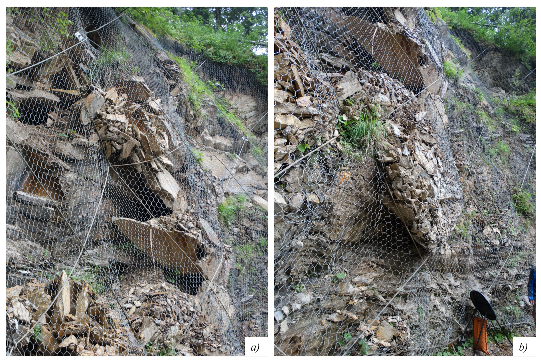
Based on the previous aspects, the leading idea of the present work is that the presence of retaining ropes can exert a confining effect similar to the constraints adopted in laboratory tests, and thus, an appropriate design can minimize differences in the resisting mechanism between in situ and laboratory conditions, or, in the case of anchor punching, it can prevent failure propagation (
Figure 2). Starting from the scheme proposed by Giacchetti and colleagues [
9,
23], a modified and enhanced design procedure for pinned drapery meshes for rock slopes is presented. The paper is organized as follows:
Section 2 highlights the proposed design procedure, subdivided into anchors (
Section 2.1), mesh (
Section 2.2), and ropes (
Section 2.3). An example is provided in
Section 3. Finally, conclusions and future perspectives are presented.
2. System Design
The design of a reinforced drapery system aims to prevent both global instability of the surficial part of the slope and local instability due to the detachment of a single block inside the anchor spaces [
9,
23]. The surficial, that is, cortical, instability is assumed to be of limited depth
s and to involve an unstable band parallel to the slope only. The sliding surface is assumed to be bounded by a joint parallel to the slope, whose inclination is
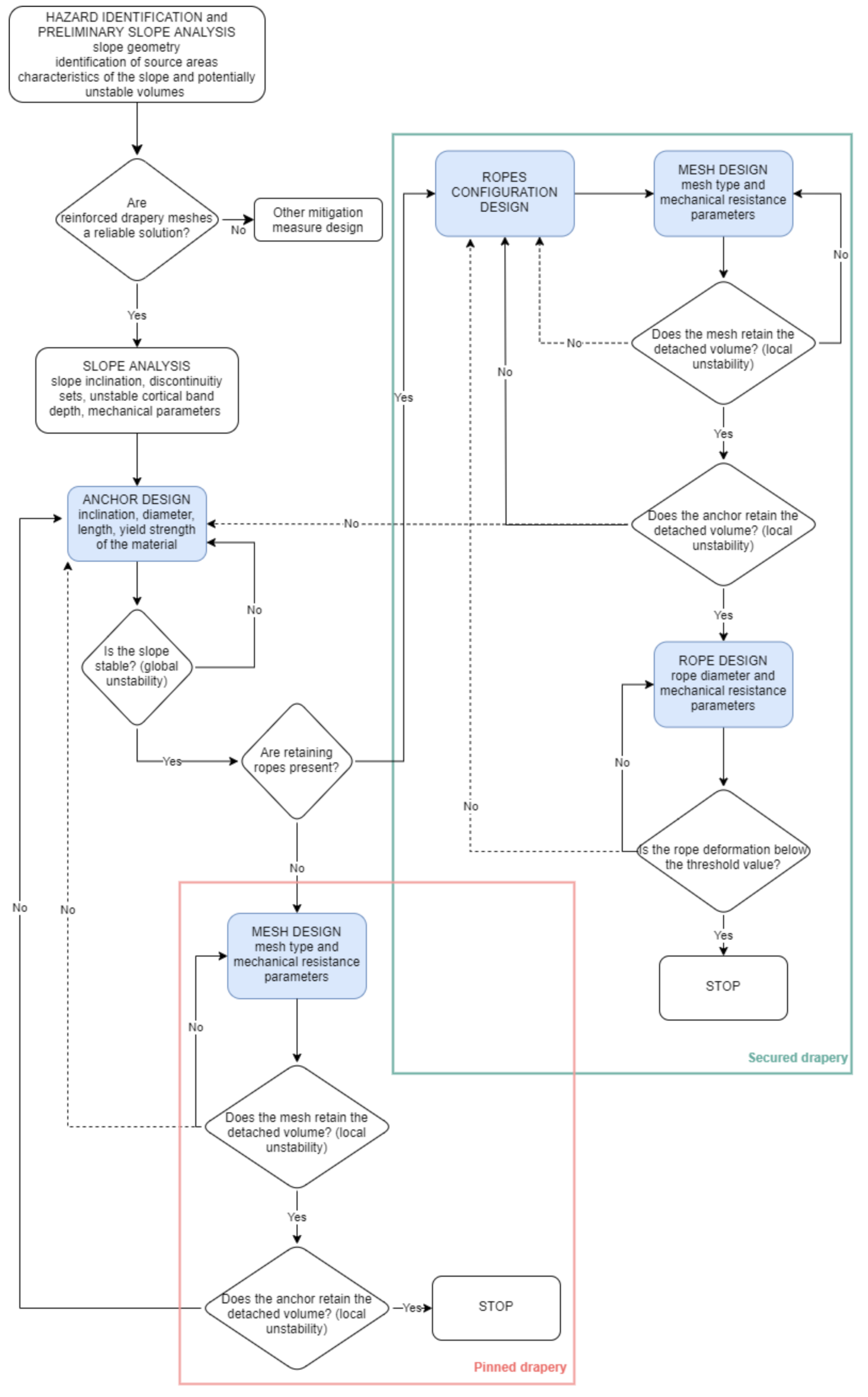
. Inside this zone, different discontinuity sets can be individuated, which can induce the detachment of single blocks. Considering both the cases of pinned and secured draperies, the design flowchart (
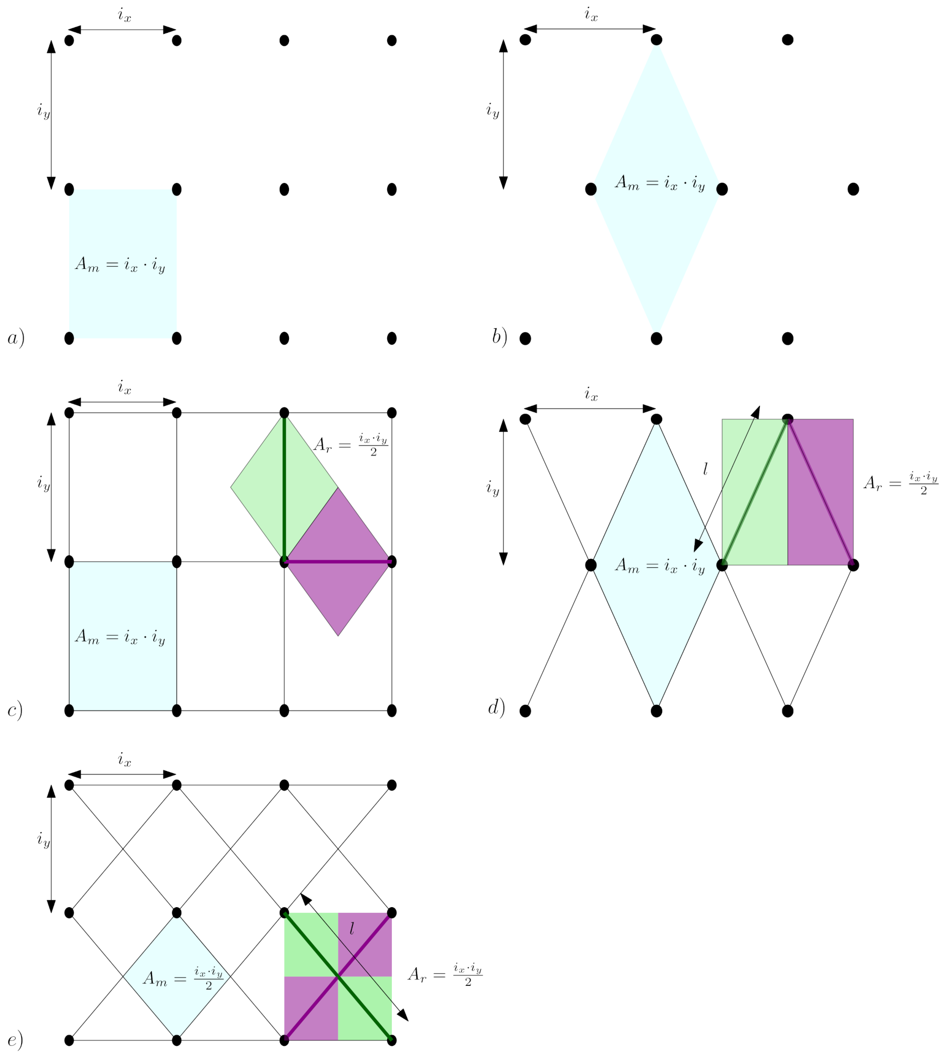
Figure 3) starts with the design of the bolts that have to sustain both the unstable section of the slope and single blocks that eventually detach and are stopped by the net. Secondly, the mesh and the ropes (if present) are designed to retain the detached blocks among the anchors. Generally speaking, the mesh is designed by dividing it into single portions that do not interact with each other. Each portion, whose area is
, is individuated in the space among four anchors in the absence of ropes or in the space among four intercepting ropes if ropes are present (
Figure 4).
As mentioned in
Section 1, the presence of ropes allows computing the punching resistance force of a mesh panel from laboratory measurements according to ISO 11437, where the panel is laterally constrained, decreasing the epistemic uncertainties due to both the difference between lab and in situ conditions and the modeled static scheme of independent portions, hinged at the extremes. The installation of ropes, assumed to be not too slack and in contact with the slope, thus prevents the mesh from moving locally near the anchor when deformed by a detached block, as this type of motion can cause a local rupture of a single wire, which plasticizes and is subjected to tensile forces (
Figure 5). The rupture can propagate, especially in the case of a single wire mesh, as shown in the literature. Consequently, in the case of pinned drapery, the bearing resistance of the mesh should also be verified against the puncturing force acting at the plates of the anchorages.
In the following, the single steps of the design are explained in detail. Refer to
Table 1 for the list of symbols.
2.1. Anchor Design
The reinforced drapery mesh constitutes a mixed passive–active system to mitigate rockfall hazards. The anchors prevent instability of the cortical zone of the slope. Generally, the installed anchors are not prestressed, i.e., bolts, and thus, they are treated as elements that apply a resisting force only after the movement of the slope. Thus, by definition, bolts provide passive support; i.e., they are assumed to increase the resisting force of the slope along the sliding surface, as defined in
Section 2.
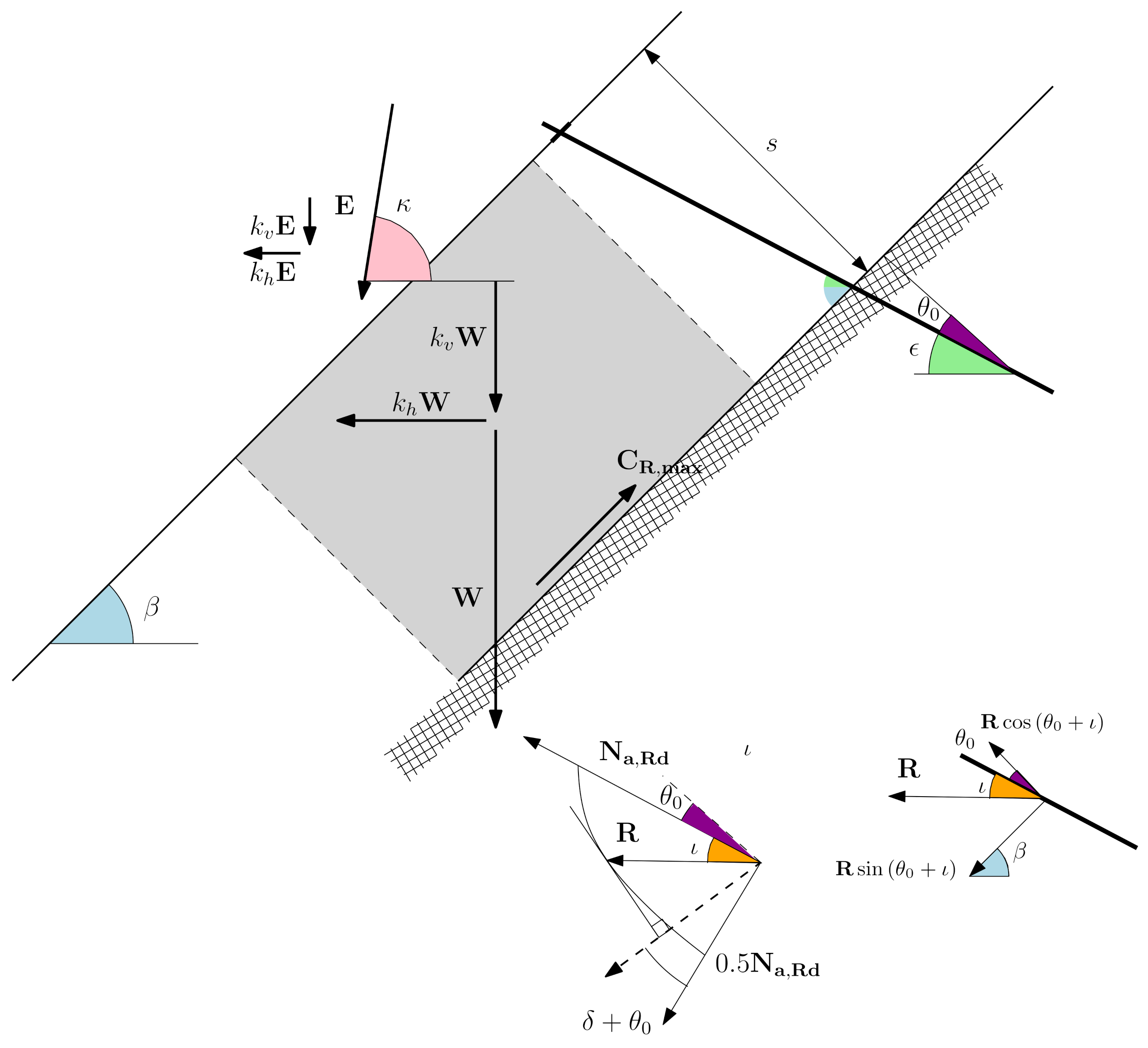
In the proposed approach, based on the limit equilibrium method on an infinite slope, the shear resistance contribution to slope stability due to the bolts is computed as a force along the sliding surface,
(
Figure 6) [
29,
30]. This approach is based on the assumption that the plastic work of the force acting on the bolts at the breaking surface (tensile and shear forces) is at its maximum; i.e., the maximum allowable yield tensile stress on the bolt is mobilized. The force on the bolts is caused by relative joint movements while also accounting for the dilatancy
of the sliding surface. The modulus and direction
of the resultant force
R on the anchor vary as functions of the displacement of the cortical zone: referring to the plastic flow rule, the displacement is normal to the elliptical yield surface at
R, which can be found graphically by tracing a line orthogonal to the displacement and tangent to the elliptical yield surface (
Figure 6). Thus,
is given by the sum of the frictional contribution, proportional to the component of
R normal to the sliding surface, and the cohesive contribution, proportional to the component of
R parallel to the sliding surface, according to:
where
is the inclination of the anchor with respect to the slope normal, and
is the friction angle of the sliding surface. The inclination
of the force and the inclination of the anchor are related according to:
Following the Tresca criterion to evaluate normal-shear forces, the resultant force
R can be computed as:
where
is the tensile yield resisting force of the anchor.
Once selected, the geometrical and mechanical parameters of the anchors and the driving and stabilizing forces along the sliding joint are computed, accounting for the self-weight of the rock among the anchors, the snow load, and other possible external loads. In the framework of the partial safety factor design approach [
31], the design values of unfavorable
and favorable
actions can be computed, and the slope stability analysis can be performed by requiring:
where the minimum safety factor
is selected by the designer according to the reliability of the input parameters as well as the adopted method. Note that
and
are related to the sliding surface. For the adopted theory, the fulfillment of the inequality of Equation (
4) also implies the structural assessment of the anchors themselves. Considering the limit condition and
, the rate of work of the anchors can be evaluated as:
Thus, the tensile force acting on each anchor can be evaluated as
. This force should be compared with the pull-out capacity of the element, assumed to be the minimum among the interface resistance between the body of grout and the steel tendon and the grout/rock interface along the stable part of the rock mass
. The minimum theoretical total length of each anchor,
, is:
where
is the length in the weathered mass (equal to
), and
is the length in which plastic phenomena occur (approximately varying from 0.10 m for hard rock up to 0.45 m for very weak rock [
32]). It is worth noting that the pull-out resistance of the anchor should be higher than the tensile force developed by the stripping by the mesh due to the retention of single blocks.
2.2. Mesh Design
The mesh is designed to retain the detached blocks in delimited portions (
Figure 4), which allow the accumulation of debris/blocks within them without excessive deformation. The mesh should be verified with respect to tensile stresses induced by this accumulation. The design approach starts by considering that each portion of the mesh, taken individually, deforms under the punching effect of the block until the rupture of the mesh occurs. A standard laboratory test procedure defined in [
26,
27,
28] was adopted to evaluate the bearing capacity of the mesh and its load–deformation relationship until the maximum displacement is reached before the rupture. The test consists of loading a panel of the net (
m) perpendicularly to its plane by means of a hemispherical shaped press, located at the central point of the panel and moving with a speed lower than 10 mm/s. It is worth mentioning that, for equal mesh panels, the mode of deformation and, consequently, the maximum allowable punching action vary according to the block shape, its position inside the panel, and panel constraints.
The method proposed herein to assess each portion of mesh, taken individually and henceforth simply called mesh, starts from the assumption that the mesh, such as mesh made of steel wires, has no flexural stiffness, and its deformation is limited to ensure compatibility between in situ and laboratory constraints. The suggested design thus uses a hybrid approach, which starts from the evaluation of the action normal to the mesh , i.e., the main action responsible for its deformation, in the limit equilibrium condition, i.e., in the undeformed condition, for a portion of mesh. This represents the maximum puncturing action that can be mobilized. The displacement is then evaluated on the basis of the load–displacement curve obtained from the laboratory test, assuming that it occurs in the center of the panel. The acting tensile force is then evaluated in the deformed configuration and is compared to the tensile resistance, evaluated through the previously mentioned standardized tensile strength test procedure.
To evaluate potential block detachment and the worst accumulation condition, a geological survey is required to investigate the discontinuity sets. The considered volume is the maximum that can be detached, and it is defined by the anchor spacing, the unstable superficial rock mass, and the orientation of the discontinuity
that involves the greater volume. This orientation represents the sliding plane of the block. Depending on the geometry, the projection of the shape of the block on a vertical section can thus be trapezoidal or triangular, and the volume
can be computed as:
where
is the inclination of the anchor with respect to the horizontal, and
.
In the undeformed condition, considering
to be the difference between the driving
and the stabilizing
forces exerted by the detached block along its sliding plane,
can be computed as (
Figure 7):
The maximum deformation
, i.e., the central displacement of the mesh during the laboratory test at
, is evaluated from the outputs of the laboratory tests through the
relationship. An angle of deformation
can be obtained as:
where
and
are the distances between two anchors along the horizontal and vertical directions, respectively, and
represents a model factor, whose meaning is discussed in
Section 2.2.1.
Once
is determined, the tensile forces acting on the upper
and lower
parts of the mesh portion in relation to its center are obtained through the equilibrium equations in the deformed configuration:
These values have to be compared to the tensile resistance of the mesh .
As explained in
Section 2.3, the load of the mesh is transferred to the ropes and then to the anchors. For pinned drapery systems, the load is directly transferred to anchors, and the detachment of a block inside a portion of mesh that is not retained by ropes also causes the deformation and stress of the mesh at the mesh–plate connection. Consequently, for pinned drapery meshes, in a first approximation, the tensile resistance of the steel wires intercepted by the plates should be verified against the slope normal force
.
2.2.1. Model Factor for Mesh Deformation
The model factor
applied to mesh deformation should encompass all possible variables, i.e., those related to (i) the differences between in situ and laboratory conditions, (ii) the adopted design scheme with individual panels with controlled deformability, and (iii) the choice of a given load and boundary configurations of the laboratory test. Considering secured draperies without retaining ropes, Pol et al. [
33] proposed an equation to correct the force–displacement response, taking into account the geometrical dimensions of the press, panel, and anchors; the press eccentricity; and the multiple panel load configurations. This last variable is assumed to be the worst condition. However, the shape of the punching element and its possible fragmentation are neglected.
Usually, a value
is expected since in situ conditions are more variable than those in a laboratory setup. The presence of retaining ropes can decrease the value of the correction, assuming that they provide boundary constraints close to the laboratory values, applying pressure to the mesh towards the slope face able to guarantee the activation of friction forces between the mesh and the slope face. Moreover, when the mesh deforms, the ropes prevent stresses from concentrating near the anchor plates. Qualitatively speaking, the failure mode of the mesh depends on the number of wires intercepted by the detached block [
25] and by the constraint elements. An anchor plate can intercept from 8 to 10 wires, while a rope can intercept from 15 to 40 (according to panel dimensions and mesh features), enabling better stress distribution. The more slack or the more deformable the installed ropes, the more that this assumption differs from reality. Thus, the elongation of the ropes should be assessed and limited as detailed in
Section 2.3.
2.3. Rope Design
As explained in
Section 2.2, the design of the mesh is performed considering individual portions that are laterally constrained. Consequently, the assessment of the ropes is also performed for individual portions (henceforth simply called rope), whose undeformed length
, in the absence of a gravitational load, is computed as:
where
l is the distance between anchors (
Figure 4), and
is the initial deflection. Due to its gravitational load
(dead load), the rope installed between two anchors is subjected to a tensile force
that can be computed through an iterative procedure starting by assuming a deflection
equal to
and iteratively solving the following equations:
until convergence, where
is elongation due to the gravity load, and
and
are the apparent elastic modulus and the nominal area of the rope, respectively.
The main purpose of the rope is to transfer the loads from the mesh to the anchors, thus ensuring that working conditions are similar to those in laboratory tests by fixing the rope elongation
, which should be smaller than a threshold
. The latter is defined as:
where the first term of the right side is the maximum displacement at failure, and
is the maximum tensile resistance. The second term refers to the maximum deflection
, defined by the designer. Based on the authors’ experience,
.
Thus, the maximum allowable tensile force is:
and the ultimate load
is:
where the maximum deflection
is:
The ropes are subjected to the load transferred from the mesh. In the hypothesis that the ropes provide an efficient constraint for the mesh, the proposed static scheme for the rope (subdivided into individual elements of length
l) accounts for support at the anchorages, while, in addition to the fact that load configurations can vary from case to case, the worst scenario is considered. Consequently, assuming a horizontal/vertical rope pattern, a distributed load along its entire length is assumed, and two adjacent mesh panels are assumed to both load the rope. Combining the forces in the neighboring mesh panels results in a total force proportional to
. Considering the proposed area of influence for each rope
as in
Figure 4, the load
is equal to
. Adopting the same iterative procedure proposed in Equations (
13)–(
15), the tensile force acting on the rope
and its real deflection
can be computed. The safety of the rope must be assessed following the usual approaches for steel cables reported in Eurocode 3 [
34]. The working rate is provided by the ratio between the acting loads
and
.
3. Example
Focusing on the mesh and rope design, in this section, an example of the novel methodology is proposed. A squared anchor pattern with both
and
equal to 3 m is installed, as commonly adopted in current practice. Two cases are considered: Case 1 represents a squared rope pattern (
Figure 4c), and Case 2 is a rhomboidal rope pattern (
Figure 4e). The slope angle
is equal to 70
, while the worst joint inclination
is equal to 40
, with a friction angle of 30
. Applying the partial safety factors proposed by the Italian regulation [
35] to the effect of the actions, the obtained
due to the possible detached block is equal to 44.3 kN for Case 1 and, due to the halved area
, is equal to 22.2 kN for Case 2. Similarly, the punching action
on the mesh is equal to 22.4 kN in Case 1 and 11.2 kN in Case 2. In this example, retaining ropes with a diameter of 14 mm, a cross-sectional area
equal to 115 mm
, a tensile strength grade of 1570 MPa, a minimum breaking force of 162 kN [
36], and an apparent elastic modulus
of 120 GPa are considered. The distance between anchors
l is equal to 3 m in Case 1 and 4.24 m in Case 2, resulting in a maximum elongation
equal to 0.02 and 0.028 m for Case 1 and Case 2, respectively, i.e., about 1% of the rope length. In Case 1, the maximum deflection
is 0.153 m, the ultimate load
is equal to 25.9 kN/m, the real total deflection
is 0.142 m, and the acting load
is equal to 9.7 kN/m. In Case 2,
is 0.217 m,
is 15.8 kN/m,
is 0.201 m, and
is 6.8 kN/m. The working rate of the rope is around 37% in Case 1 and around 43% in Case 2, showing that the latter would be slightly more effective from a design point of view.
This reveals that the working rates of ropes are similar, while the mesh-puncturing action in Case 2 is halved compared to Case 1. From a design point of view, the rhomboidal configuration of Case 2 provides a considerable cost reduction for the required mesh type.
It is worth mentioning that, generally speaking, considering a pinned drapery (namely, Case 3), the action and are equivalent to Case 1. The difference lies in the fact that the applied safety factor in Case 3 should also encompass the model uncertainties related to the assumed static scheme and to the greater difference in boundary conditions between laboratory and real cases. Furthermore, the mesh should also be verified to prevent anchor punching, ensuring that the tensile resistance of the steel wire intercepted by the plate is higher than . Consequently, mesh in which a single wire has very high tensile resistance is often required.
4. Conclusions
Reinforced drapery meshes constitute an effective solution for rockfall risk mitigation, especially along slopes directly facing infrastructures. Due to the presence of anchors, they act as both preventive and protective risk mitigation measures. Several technological solutions have been devised in recent years, with different types of meshes and with or without retaining ropes. Despite this, a codified design method accounting for the beneficial contribution of the ropes in secured drapery has not yet been defined. In the present paper, an enhanced design procedure for reinforced drapery meshes for rock slopes is presented, starting from the scheme proposed by Giacchetti et al. [
9,
23]. Anchors are designed to prevent slope failures along a shear plane in the weathered surficial part, while the mesh is subdivided into portions, each of which should stop single detached blocks. The resistance of the mesh is assessed through codified laboratory tests [
26,
27,
28], with a test procedure that differs from in situ real conditions. In this framework, the presence of retaining ropes allows constraints similar to those in the laboratory, as well as the assumption of individual portions of mesh for the design. The proposed design method includes the contribution of the ropes, whose elongation should be limited such that failure of the mesh near the anchor plates is prevented. A distributed load configuration is considered to be representative of the worst real situation, and the static scheme accounts for the portion of ropes in between two anchors. Moreover, the rope pattern enables the consideration of smaller portions of mesh compared to pinned drapery systems, providing possible cost reductions in the choice of the mesh type. Future studies are required to better understand the behavior of such a complex system and should address various aspects, such as different load patterns for the mesh and the ropes, and should also employ numerical simulations. Finally, for design purposes, an accurate evaluation of
is needed for different boundary conditions, rope patterns, and panel sizes.


