Abstract
To solve the mismatch between the comprehensive mechanical properties of the spinal fusion cage and body, a fusion cage inner hole design method based on controllable TPMS-P to characterize the inner hole structure is proposed to solve the related problems. Firstly, the method of TPMS-P parameterization was used to construct the bionic porous structure model, which was designed as the linear gradual internal porous structure model. Then, we optimized the topology of the obtained porous structure implants to achieve precise control of the overall comprehensive mechanical properties of the fusion cage structure and obtain an optimized model that matched the mechanical properties of the fusion cage. To verify whether the method met the requirements, its simulation model was established. The porous structure was fabricated by selective laser processing, and its properties were tested and analyzed. The results show that its yield strength is 79.83 MPa, which match well with spinal bone tissue.
1. Introduction
The spinal implant devices manufactured by the existing technology have obvious shortcomings, and the comprehensive mechanical properties of the solid metal implants do not match, resulting in a serious stress shielding effect between the solid metal implants and the host bone [1,2]. The ideal interbody fusion cage implantation device should have good biocompatibility, can complete the new bone growth in an effective time, and achieve real interbody fusion. In addition, the device located in the load-bearing position needs to have certain comprehensive mechanical properties. When constructing the implant model of the personalized interbody fusion cage, it is necessary to comprehensively consider the biomechanical properties, porosity, pore distribution, connectivity, and other factors of the fusion cage. The microporous structure design of the fusion cage is the key part of the process of spinal repair and replacement. In the design method of the porous structure model, the typical porous structure design method includes a computer aided design porous structure design method, based on the CT scanning image mapping porous structure design method and TPMS porous structure design method. The computer aided design porous structure design method is a combination of computer graphics and CAD program modeling, through the construction of solid geometry, to build a complex model. This method, as an attempt of the early design of the porous scaffolds, only carries out simple Boolean operations and arrays, and the parameters, such as porosity and gradient pores of the scaffolds, are poorly controllable, as shown in Figure 1A [3]. The method of model reconstruction based on medical images is generally through the analysis and processing of CT or MRI medical data images, using related algorithms to extract features of specific areas and 3D model reconstruction in professional software. According to the number of large-scale images of tibia under the DICOM standard, a clear bone microstructure image was obtained by using image binarization, thermal pixel removal, closure operation, and other algorithms, and then the perimeter and area of bone microstructure pores were measured by the straight line fitting method based on the least square method, as shown in Figure 1B [4,5]. Although the bone tissue 3D model reconstruction algorithm based on medical images can obtain structural and morphological features, and is similar to bone tissue, its implementation process is generally complex and requires high software algorithms, system hardware, and users. The implicit curved surface porous element construction method can effectively parametrically control the pore shape, pore size, specific surface area, porosity, and other parameters of the porous unit, which makes the mechanical and biological properties of the designed porous implant meet the ideal requirements, and has a positive impact on cell migration and tissue inward growth, which has attracted the attention of researchers [6,7,8,9,10,11]. The triply periodic minimal surface (TPMS), as a kind of implicit surface, has the advantages of a controllable parameter design and integrity of model expression, and has the advantages of ideal connectivity and controllability, which provides a new design method for the construction of existing porous implants [12,13,14]. The TPMS construction method can be used to construct a porous structure implant model with a linear change of pore structure. By regulating the pore structure, the pore structure of the porous implant changes linearly from the surface to the inside, so that the surface elastic modulus of the porous implant, in contact with bone tissue, is close to that of bone tissue, as shown in Figure 1C [15,16,17].
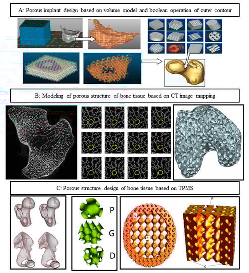
Figure 1.
Design method of porous structure. (A) Computer aided design porous structure design method; (B) based on the CT scanning image mapping porous structure design method; (C) TPMS porous structure design method.
The above studies show that the bone tissue microporous structure design based on the TPMS curved surface porous structure design method can optimize the mechanical properties of porous implants and can be used as the characterization of the inner pore structure of ideal bone implants. However, the following problems need to be solved: (1) at present, the microporous structure of TPMS bone tissue is generally constructed by only one kind of pore-forming element, even if two kinds of elements are used to construct the pore structure element, the boundary of the element is discontinuous and there is a phenomenon of local stress concentration. (2) The existing TPMS inner hole structure uses conventional finite element analysis to realize structure distribution topology optimization and gradient design, which cannot directly predict the comprehensive mechanical properties of the inner hole structure, and the simulation model has a large amount of data, which consumes a lot of computing resources in the follow-up simulation and optimization design process. In this paper, a design method of the porous structure based on parameterized TPMS is proposed. The three-dimensional periodic minimum surface method is used to further realize the correlation mapping between the structure and performance. Through the rapid optimization of the shape and spatial distribution of the micropore structure, the best match between the comprehensive mechanical properties of implant parts and defective bone tissue is realized.
2. Materials and Methods
2.1. Test Material
The test material was selected, EOS, original imported titanium alloy Ti6A14V powder; titanium alloy powder was prepared by argon atomization, the particle size range was 15–45 , the sphericity was 98.9%, the fluidity was 47.2 s/50 g, the powder quality met the requirements, and the chemical composition is shown in Table 1. Figure 2 shows the micromorphology of titanium alloy powder with a small number of satellite planets, high sphericity, and good fluidity. To prevent the powder from dampness during transportation and storage and affect the fluidity of the powder, the powder is kept in a (100 ± 5 °C) oven for 6 h before use and dry.

Table 1.
Ti6Al4V chemical composition (Wt%).
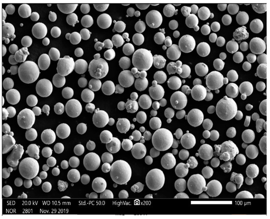
Figure 2.
Microstructure of Ti6A14V powder with magnification of 200 times.
2.2. Manufacturing Equipment
The SLM forming equipment used in this study is the SLM rapid prototyping machine EP-M250 developed by Beijing Yijia 3D Technology Co., Ltd. (Beijing, China), as shown in Figure 3. The main parameters are as follows: equipped with German Yb fiber laser, the wavelength being 1075 nm, and the spot diameter about 70–100 µm—it had the advantages of reliable performance, a long service life, high conversion efficiency, a beam mode close to the fundamental mode, etc. The maximum forming size was 250 × 250 × 300 mm; the thickness of the forming layer was 20–100 µm; galvanometer laser scanning, scanning speed 5–7000 mm/S; the molding room was filled with argon or nitrogen, the oxygen content could be controlled below 0.01%, and the indoor environment was well controlled.

Figure 3.
SLM forming principle and forming equipment EP-M250.
2.3. Design and Performance Simulation Analysis of Porous Structure
In the spinal bone, the pore sizes of different segments of the bone are different, and the distribution of the pore sizes are uneven. The optimal fusion cage bone implant should have similar mechanical and biological characteristics to the original spinal bone. It is of great significance to study how to optimize the spatial distribution of pore structure and pore structure in spinal implants. In this paper, through the construction method of TPMS, the implicit function equation model, the bionic porous structure model and the linear gradual porous structure model are constructed parametrically, and the pore shape, size, linear change rate, and other structural characteristics of the porous model are changed by adjusting the construction parameters of the model, to obtain the ideal porous structure implant parts [18,19,20,21,22]. The detailed design steps are shown in Figure 4.
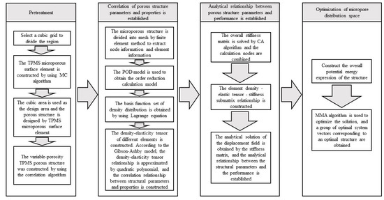
Figure 4.
TPMS pore structure parameters—performance mapping and pore structure spatial distribution optimization, comprehensive mechanical control process.
Step 1: pretreatment: construction of TPMS porous structural units. Taking the regular hexahedral mesh region as the design area, the porous material was designed by digging holes in each hexahedral mesh element; the corresponding relationship between the TPMS element parameters and density distribution was established.
Step 2: homogenization process: we determined the equivalent tensor matrix of the microstructure unit. We extracted the hexahedral grid node information and element information, solved the overall stiffness matrix of the structure, constructed the correlation matrix, including grid node information and material properties. We used the proper orthogonal decomposition (POD) model reduction algorithm to model and map the finite element mesh, and calculate the equivalent elastic tensor matrix corresponding to each mesh sample.
Step 3: structural optimization design: introducing the combinatorial approximation technique (combined approximation, CA), the equivalent tensor matrix of the grid structure was obtained from step (2) to assemble the elastic matrix. The approximate analytical expression of the displacement field was solved in the case of small disturbance of the stiffness matrix, and the optimization problem of the spatial distribution of porous structures was transformed into the standard geometric parameter optimization problem of the equivalent continuous solid model.
Step 4: the method of moving asymptotes (MMA) was used to optimize the set region, and after, the pore shape parameters of each element were obtained, the corresponding porous structure was constructed. The approximate analytical relationship between the structural descriptor and the displacement field was established, which avoids multiple meshing and a finite element simulation, which will greatly accelerate the optimization design process. The core includes the correlation between porous structure parameters and properties and the correlation between properties and performance based on TPMS.
To facilitate the application of pressure, considering the shape of the upper and lower end of the actual interbody fusion cage, a horizontal solid is added to the upper and lower surface of the best TPMS porous structure, as shown in Figure 5:
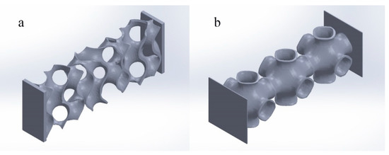
Figure 5.
Optimal TPMS variable pore porous structure entity. ((a) Optimal TPMS variable pore porous structure entity-G; (b) optimal TPMS variable pore porous structure entity-P).
2.4. Study on the Performance of Porous Structure Simulation Model
Through the above TPMS porous structure model design and spatial distribution optimization, the optimal TPMS porous structure solid model with variable pore sizes was obtained. To verify whether its mechanical properties meet the requirements, it is necessary to simulate and analyze its mechanical properties. Based on TPMS homogeneous porous structure modeling, TPMS porous structure units with corresponding porosity were mainly used to build. It is completed in Materialise Magics 21.0 software. The schematic diagram of the TPMS uniform porous structure model is shown in Figure 6A, where a, b, c, are, respectively, the G-TPMS model (a: G model 3 based on the TPMS non-uniform porous structure (hereinafter referred to as G-3); b: G model 2 based on the TPMS non-uniform porous structure (hereinafter referred to as G-2); c: G model 1 based on the TPMS non-uniform porous structure (hereinafter referred to as G-1); and where d, e, f, are, respectively, the P-TMPS model (d: based on the TPMS uniform porous structure P model 3 (hereinafter referred to as P-3); e: based on the TPMS homogeneous porous structure P model 2 (hereinafter referred to as P-2); f: based on the TPMS uniform porous structure P model 1 (hereinafter referred to as P-1)).
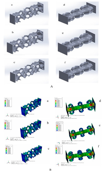
Figure 6.
TPMS porous structure models and simulation results. ((A) (a: G model 3 based on the TPMS non-uniform porous structure; b: G model 2 based on the TPMS non-uniform porous structure; c: G model 1 based on the TPMS non-uniform porous structure; d: based on the TPMS uniform porous structure P model 3; e: based on the TPMS homogeneous porous structure P model 2; f: based on the TPMS uniform porous structure P model 1). (B) (a: the maximum equivalent stress of G-1 is 95.78 Mpa;b: the maximum equivalent stress of G-2 is 111.5 Mpa; c: the maximum equivalent force of G3 is 124.7 Mpa; d:the maximum equivalent stress of P-1 is 83.83 MPa; e: the maximum equivalent stress of P-2 is 84.36 MPa; the maximum equivalent stress of P-3 is 84.49 MPa)).
Considering that the TPMS porous structure entity is mainly used in the lumbar interbody fusion cage, mainly under pressure, this paper only carries on the corresponding compression simulation analysis. In this paper, the grid was divided by HyperMesh 14.0 software, and after the division was complete, it was imported into Abaqus 19.0 software for simulation analysis. The simulation parameters of material Ti6Al4V are as follows: density was 4.4 × 10⁹ kg/m3, Young’s modulus was 1.17 × 10¹¹ Pa, Poisson’s ratio was 0.342, and pressure was 2 × 10⁸ Pa. To facilitate the application of boundary conditions, planar entities are added to the upper and lower surfaces of TPMS porous solids. The results of the simulation analysis are shown in Figure 6B, where a, b, c, are, respectively, maximum equivalent stress (a: the maximum equivalent stress of G-1 is 95.78 MPa, b: the maximum equivalent stress of G-2 is 111.5 MPa, c: the maximum equivalent force of G3 is 124.7 MPa). We can also calculate the porosity of the three porous structures respectively (G-1:86.3%, G-2:77.60%, and G-3:74.41%). Where d, e, f, in Figure 6, right side, are, respectively, d, e, f’s maximum equivalent stress (the maximum equivalent stress of P-1 is 83.83 MPa; that of P-2 is 84.36 MPa; and that of P-3 is 84.49 MPa). Moreover, we can obtain porosity of the three porous structures, respectively (P-1:92.24%, P-2:90.54%, and P-3 89.06%). We unify the maximum equivalent stress of two different TPMS structures with different porosities into a broken line diagram, as shown in Figure 7.
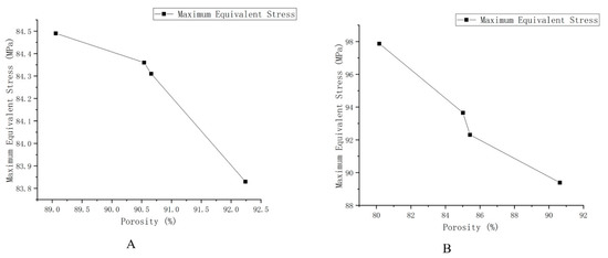
Figure 7.
Schematic diagram of the maximum equivalent stress of different structures and different porosity. (A) The maximum equivalent stress of G structure with different porosity. (B) The maximum equivalent stress of the P structure with different porosity.
As shown in Figure 7, the results show that the maximum equivalent stress decreases with the increase of porosity and increases with the increase of loading force/pressure. The TPMS porous structure with variable pore sizes has a more appropriate maximum equivalent stress and porosity than the non-TPMS uniform porous structure and the TPMS-based uniform porous structure. Moreover, the TPMS-based uniform porous structure has a more appropriate maximum equivalent stress and porosity than the non-TPMS uniform porous structure. According to two related literatures [23,24], the porosity of 10–95% and the compression strength of 0.5–350 MPa can well meet the mechanical properties and medical needs, so the TPMS porous structure entity designed in this paper is reasonable, and it could overcome the current design defects of lumbar interbody fusion cage and help patients accelerate their recovery.
2.5. Simulation of Actual L3–L4 Vertebral Body Model
The corresponding models of cortical bone, cancellous bone, cartilage, upper endplate, lower endplate, nucleus pulposus, fibrous annulus, and ligament are constructed by reverse engineering, and the material properties are given [25]. The L3–L4 vertebral body model is shown in Figure 8.
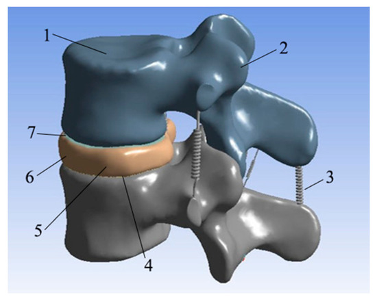
Figure 8.
L3–L4 vertebral body model. (1: Cancellous bone; 2: cortical bone; 3: ligament; 4: lower endplate; 5: nucleus pulposus; 6: annulus fibrosus; 7: upper endplate).
The lower surface of the L4 vertebral body model was restrained by displacement fixation, and then a force of 350 N was applied to the upper surface of the L3 vertebral body model as a simulation of the weight of an adult male upper body. After the vertical downward surface load was applied, six different types of loads were set to simulate the six movements of the human body: forward bending, backward extension, left bending, right bending, left rotation, and right rotation. The simulation results are shown in Figure 9.
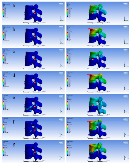
Figure 9.
Diagram of finite element analysis results (the figure on the left shows equivalent stress and the figure on the right shows total deformation). ((a) Standing still; (b) left bend; (c) right bend; (d) forward flexion; (e) backward extension; (f) left rotation; (g) right rotation).
As shown in Figure 9, through the results of the above finite element analysis, it can be found that there will be areas with different colors in different total deformation diagrams. It can be found that the deformation value of the red area is the largest and the deformation value of the blue area is the smallest. When people are moving, the whole body will follow the movement, and the spine will move with it, resulting in corresponding deformation. This time we fixed the lower surface of the L4 vertebral body, and the displacement of the L3 vertebral body changed, but the overall shape change of the bone was relatively small. The main shape variable was generated on the intervertebral disc L3–L4 between L3 and L4 vertebral bodies. It can also be seen that when people are standing still, the deformation of the vertebral disc is small. The total deformation in the L3–L4 segment was 0.60349 mm, which is on the upper surface of the L3 vertebral body. From this, we can draw the following conclusion: during human movement, the deformation of the spine is mainly due to the deformation of the spinal intervertebral disc. Considering that the equivalent stress values of the L3–L4 vertebral body model are different in each motion state, according to the simulation performance results, it can be found that the optimal TPMS variable pore porous structure entity designed by us meets the corresponding equivalent stress range, and is close to the human body itself, which can well avoid the situation of “stress shielding”.
3. Experiment and Discussion
3.1. Experiment
To verify the feasibility of the porous structure proposed in this paper, in the application of the interbody fusion cage, the printing and pressure analysis of SLM porous structure were carried out. The EP-M250 introduced earlier was selected as the printing equipment, and the material was titanium alloy powder. The different porosity structures of TPMS-G and TMPS-P were printed and the mechanical properties were tested. The microstructure of the printed hole structure were detected by SEM. Considering the actual processing process, due to the different process parameters of SLM printing, such as laser power, laser spot diameter, powder layer thickness, scanning speed, and whether the substrate was preheated or not, will lead to some specific phenomena of bone tissue engineering scaffolds. The SLM printing and SEM analysis process of bone tissue engineering scaffold in this paper are shown in Figure 10, where the a diagram shows the L3–L4 vertebral body model; the b diagram shows the interbody fusion cage in the L3–L4 vertebra model printed by SLM; the c diagram shows the pore structure inside the interbody fusion cage, and d and e are SEM analysis diagrams of the porous structure.
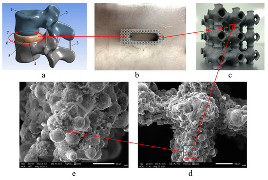
Figure 10.
SLM printing and SEM analysis process of bone tissue engineering scaffolds. ((a) L3–L4 vertebral body model. (b) Interbody fusion cage in the L3–L4 vertebra model printed by SLM. (c) Pore structure inside the interbody fusion cage; (d) and (e) SEM analysis diagrams of the porous structure).
The printed results were processed by scanning electron microscope (SEM). It can be seen that obvious defects and cracks occurred in the printing process, and all appear in the central area of the structure. The main reason for this phenomenon is that the Gaussian distributed laser energy caused a large temperature gradient in the material in the laser scanning area, and the uneven deformation of the material in each area during the cooling process caused residual stress. Moreover, during the SLM printing process, the heat conduction between the powder layers in the z direction was poor, resulting in a temperature gradient, resulting in different residual stress distributions in the upper and lower parts of the print. The rapid heating and cooling during the SLM process will produce huge temperature gradients. This temperature gradient will cause the material to expand or contract, causing residual stress. If the maximum tensile strength of the alloy is exceeded, cracks will form. Based on the analysis of its generation mechanism, this paper proposes two methods of substrate heating and material heat treatment to suppress cracks and pores. When the substrate is used for preheating, it indirectly increases the input of external energy, reduces the laser energy, and the temperature distribution of the entire substrate tends to be consistent, to reduce the effect of residual stress. From the nature of the material itself, increasing the temperature can increase the material toughness and reduce brittleness; when the same deformation occurs, it can reduce the generation of cracks.
3.2. Discussion
The corresponding TPMS porous structure was obtained by pretreatment, and the porous structure with optimal spatial distribution was obtained. For the optimal TPMS variable pore porous structure entity, non-TPMS uniform porous structure entity, TPMS uniform porous structure entity, we carry on the corresponding compression analysis, according to the numerical value, to judge whether these structures meet the actual needs of the human body. Through the detailed data of the above simulation analysis chapter, we get the following information: the P structure with variable pore size is better than the G structure, in terms of porosity and mechanical properties. It not only meets the corresponding better mechanical properties, but it also takes into account the large porosity. It can further ensure the transport of nutrients, and further promote the wound healing and rapid connection of implanted instruments with surrounding bone tissue. The maximum equivalent stress and porosity of the TPMS-based uniform porous structure are basically better than those of the non-TPMS uniform porous structure, indicating that the applicability of the TPMS-based uniform porous structure is higher than that of the non-TPMS uniform porous structure. Considering that the porosity is 10–95%, and the range of compressive strength in 0.5–350 MPa can meet the mechanical properties and medical requirements, the TPMS porous structure entity with variable pore sizes designed in this paper is reasonable [26].
To judge whether the designed porous structure meets the actual needs, we constructed the L3–L4 vertebral body model by reverse engineering, carried out the corresponding compression analysis, and gave the corresponding parameters according to different bone tissues to obtain the stress–strain state of different bone tissues under the actual motion state of the human body. Through the comparison of the relevant data in the fourth chapter, we can judge whether the TPMS porous structure, with variable pore sizes designed above, meets the needs of the actual human body. Finally, it can be found that the TPMS porous structure with variable pore sizes can meet the actual needs.
Finally, we analyzed the performance of bone tissue engineering scaffolds. We used Ti6Al4V powder for SLM printing, and then carried out corresponding SEM analysis and compression experiments. For the specific phenomenon of bone tissue engineering scaffold: spheroidization. Through the analysis, we found that it was due to the fact that the substrate was not preheated, which led to the occurrence of this phenomenon. Spheroidization will make the metal powder “not solidified” to form a continuous and smooth molten pool, which makes the printed products loose and porous, resulting in a decline in quality. We adopted the method of preheating the substrate to heat the printed substrate, so that when the temperature of the substrate reached 80 °C, we began to print. By comparing the pictures of the two SEM analyses, we found that the occurrence of spheroidization decreased significantly. As a result, it was proven that the pre-heating treatment of the substrate could effectively reduce the formation of spheroidization. The purpose of the compression experiment was to confirm whether the performance of the bone tissue engineering scaffold met the requirements of the practical application environment. According to the compression test data, it was confirmed that the compressive yield strength of the P structure with variable pore sizes was smaller than that of the G structure, which could better meet the actual needs of the human body. In summary, the porous implant constructed by Pvariable pore could effectively reduce the “stress shielding” effect between the implant and bone tissue, and could well meet the mechanical properties and medical needs.
Then compression experiments were carried out on the porous implant. The unidirectional compression experiment was carried out on a microcomputer controlled electronic universal testing machine. The running speed of the test head was set as 1 mm/min and the maximum pressure load was set as 10 kN. The samples were compressed experiments. The samples are denoted as: Pvariable pore, P-2, Structure-2, Gvariable pore, G-3, Structure-3, Solid. Then the stress–strain curve was obtained, as shown in Figure 11.
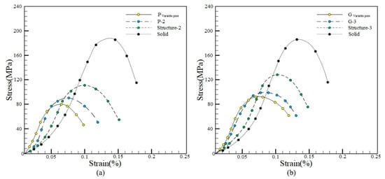
Figure 11.
Stress–strain curve. ((a) P structure stress–strain curve; (b) G structure stress–strain curve).
Figure 11 shows the compressive yield strength of different samples in the stress–strain curve. Among them, the compressive yield strength of Pvariable pore and Gvariable pore is the smallest, while that of Solid is the largest. As can be seen from the value, the compressive yield strength of the sample P variable pore is smaller than that of Gvariable pore, which could better meet the actual needs of the human body, the porous implant constructed by Pvariable pore could effectively reduce the “stress shielding” effect between the implant and bone tissue and could well meet the mechanical properties and medical requirements.
4. Conclusions
- The corresponding non-TPMS uniform porous structure entity and TPMS uniform porous structure entity were designed. Moreover, the corresponding compression analysis was carried out between it and the optimal TPMS entity with variable pore structures. By comparison, the optimal TPMS porous structure with variable pore sizes is better than the non-TPMS uniform porous structure and TPMS-based uniform porous structure. Moreover, based on the TPMS uniform porous structure being better than the non-TPMS uniform porous structure, these three kinds of porous structural entities all meet the corresponding mechanical properties and medical requirements, and all have appropriate maximum equivalent stress and high porosity.
- Through the simulation analysis of the L3–L4 vertebra model, the total deformation and equivalent stress of the human spine in six motion states were obtained. According to the comparison of the simulation results, it was found that the optimal TPMS variable pore structure entity designed by us could meet the actual needs.
- Through SLM printing, the corresponding finished parts were obtained and processed by SEM. Through the comparison of the results, it was found that pre-heating of the substrate could effectively reduce the formation of spheroidization.
Author Contributions
Conceptualization, J.Q., Y.G., H.C. and J.H.; data curation, C.Z., M.W. and X.Z.; formal analysis, W.L. and G.C.; funding acquisition, C.Z. and X.Z.; investigation, Y.G., H.C. and J.H.; methodology, J.Q., Y.G., H.C. and J.H.; project administration, J.Q., Y.G. and H.S.; resources, W.L. and G.C.; software, Z.Q., Y.C. and H.S.; supervision, J.Q., H.S., W.L. and G.C.; validation, J.Q., Y.G. and J.H.; visualization, J.Q., Y.G., Z.Q. and Y.C.; writing—original draft, J.Q., Y.G. and H.C.; writing—review and editing, J.Q., Y.G. and J.H. All authors have read and agreed to the published version of the manuscript.
Funding
The work is supported by the National Natural Science Foundation of China (51805475), Key Laboratory of Underwater Acoustic Environment Institute of Acoustic Chinese Academy of Science, the KEY Research and Development Program of Zhejiang Province (no.2021C03013), and the key laboratory for Technology in Rural Water Management of Zhejiang Province(ZJWEU-RWM-20200303B), Zhejiang Provincial Natural Science Foundation of China (Y22E055902), Open Foundation of the State Key Laboratory of Fluid Power and Mechatronic Systems, and Jiangsu Key Laboratory of 3D Printing Equipment and Manufacturing (3DL202105).
Institutional Review Board Statement
Not applicable.
Informed Consent Statement
Not applicable.
Data Availability Statement
The study did not report any data.
Conflicts of Interest
The authors declare no conflict of interest.
References
- Meng, G.; Liu, J.; Pei, G.; Yuan, Z.; Hu, Y.; Li, D.; Bi, L.; Wang, J.; Lu, R. Research progress of titanium alloy implant materials in trauma orthopaedics and joint surgery. Rare Met. Mater. Eng. 2011, 40, 533–537. [Google Scholar]
- Ding, R.; Wu, W.; Qiu, G.; Wu, G.; Wang, H.; Su, X.; Yin, B.; Ma, S.; Qi, B. Study on bone tissue engineering of porous titanium alloy scaffold by selective laser sintering. Chin. Med. J. 2014, 94, 1499–1502. [Google Scholar]
- Cheah, C.M.; Chua, C.K.; Leong, K.F.; Chua, S.W. Development of a tissue engineering scaffold structure library for rapid prototyping. part 1: Investigation and classification. Int. J. Adv. Manuf. Technol. 2003, 21, 291–301. [Google Scholar] [CrossRef]
- Hollister, S.J.; Levy, R.A.; Chu, T.M.; Halloran, J.W.; Feinberg, S.E. An image-based approach for designing and manufacturing craniofacial scaffolds. Int. J. Oral Maxillofac. Surg. 2000, 29, 67–71. [Google Scholar] [CrossRef] [PubMed] [Green Version]
- Wang, P.; Wang, S. Computer-aided CT image processing and modeling method for tibia microstructure. Bio-Des. Manuf. 2020, 3, 71–82. [Google Scholar] [CrossRef] [Green Version]
- Lu, Y.; Zhao, W.; Cui, Z.; Zhu, H.; Wu, C. The anisotropic elastic behavior of the widely-used triply-periodic minimal surface based scaffolds. J. Mech. Behav. Biomed. Mater. 2019, 99, 56–65. [Google Scholar] [CrossRef] [PubMed]
- Ma, S.; Song, K.; Lan, J.; Ma, L. Biological and mechanical property analysis for designed heterogeneous porous scaffolds based on the refined TPMS. J. Mech. Behav. Biomed. Mater. 2020, 107, 103727. [Google Scholar] [CrossRef] [PubMed]
- Shi, Z.; Zhou, X. The structure of biomimetic bone scaffold was designed based on TPMS modeling method. Machinery 2020, 47, 1–6. [Google Scholar]
- Liu, F.; Ran, Q.; Zhao, M.; Zhang, T.; Zhang, D.Z.; Su, Z. Additively Manufactured Continuous Cell-Size Gradient Porous Scaffolds: Pore Characteristics, Mechanical Properties and Biological Responses In Vitro. Materials 2020, 13, 2589. [Google Scholar] [CrossRef] [PubMed]
- Charbonnier, B.; Manassero, M.; Bourguignon, M.; Decambron, A.; El-Hafci, H.; Morin, C.; Leon, D.; Bensidoum, M.; Corsia, S.; Petite, H.; et al. Custom-made macroporous bioceramic implants based on triply-periodic minimal surfaces for bone defects in load-bearing sites. Acta Biomater. 2020, 109, 254–266. [Google Scholar] [CrossRef] [PubMed]
- Vijayavenkataraman, S.; Kuan, L.Y.; Lu, W.F. 3D-printed ceramic triply periodic minimal surface structures for design of functionally graded bone implants. Mater. Des. 2020, 191, 108602. [Google Scholar] [CrossRef]
- Melchels, F.P.; Bertoldi, K.; Gabbrielli, R.; Velders, A.H.; Feijen, J.; Grijpma, D.W. Mathematically defined tissue engineering scaffold architectures prepared by stereolithography. Biomaterials 2010, 31, 6909–6916. [Google Scholar] [CrossRef] [PubMed] [Green Version]
- Yoo, D. Heterogeneous minimal surface porous scaffold design using the distance field and radial basis functions. Med. Eng. Phys. 2012, 34, 625–639. [Google Scholar] [CrossRef] [PubMed]
- Li, Y. Optimal Design and Controllable Construction of Porous Bone Tissue Engineering Scaffold; Guizhou Normal University: Guizhou, China, 2018. [Google Scholar]
- Shi, J. Study on the Construction of Porous Structure for 3D Printing of Bone Implants; Southeast University: Jiangsu, China, 2018. [Google Scholar]
- Shi, J.; Zhu, L.; Li, L.; Li, Z.; Yang, J.; Wang, X. A TPMS-based method for modeling porous scaffolds for bionic bone tissue engineering. Sci. Rep. 2018, 8, 7395. [Google Scholar] [CrossRef] [PubMed] [Green Version]
- Li, L.; Shi, J.; Zhang, K.; Yang, L.; Yu, F.; Zhu, L.; Liang, H.; Wang, X.; Jiang, Q. Early osteointegration evaluation of porous Ti6Al4V scaffolds designed based on triply periodic minimal surface models. J. Orthop. Transl. 2019, 19, 94–105. [Google Scholar] [CrossRef] [PubMed]
- Lorensen, W.E.; Cline, H.E. Marching cubes: A high resolution 3D surface construction algorithm. ACM SIGGRAPH Comput. Graph. 1987, 21, 163–169. [Google Scholar] [CrossRef]
- Zhang, Z.; Zhao, K.; Yang, X.; Duan, M. Research on modeling method of bone scaffold based on three-periodic minimal surface and isoparametric element method. Mech. Des. Manuf. 2017, 11, 234–238. [Google Scholar]
- Pan, L. Two-Scale Optimal Design of Anisotropic Porous Structure; Zhejiang University: Zhejiang, China, 2018. [Google Scholar]
- Xu, C. Efficient Parameter Optimization Design of Porous Structure; Zhejiang University: Zhejiang, China, 2018. [Google Scholar]
- Mei, C. Analysis of Topology Optimization Algorithm of Tower Structure under Wind Load; Guangzhou University: Guangzhou, China, 2020. [Google Scholar]
- Mullen, L.; Stamp, R.C. Selective laser melting: A regular unit cell approach for the manufacture of porous, titanium, bone in-growth constructs, suitable for orthopedic applications. J. Biomed. Mater. Res. Part B: Appl. Biomater. 2009, 89, 325–334. [Google Scholar] [CrossRef] [PubMed]
- Zhou, C.; Hu, C.; Ma, F. Dynamic stress concentrations in exponential graded materials with two holes of arbitrary shape. Wave Motion. 2014, 51, 466–475. [Google Scholar] [CrossRef]
- Qin, C. Three-Dimensional Model Construction and Finite Element Mechanical Analysis of Human Spine and Lumbar Segment; Xidian University: Xi’an, China, 2014. [Google Scholar]
- Mullen, L.; Stamp, R.C.; Fox, P.; Jones, E.; Ngo, C.; Sutcliffe, C.J. Selective laser melting: A unit cell approach for the manufacture of porous, titanium, bone in-growth constructs, suitable for orthopedic applications. II. Randomized structures. J. Biomed. Mater. Res. Part B: Appl. Biomater. 2009, 92, 178–188. [Google Scholar] [CrossRef] [PubMed]
Publisher’s Note: MDPI stays neutral with regard to jurisdictional claims in published maps and institutional affiliations. |
© 2021 by the authors. Licensee MDPI, Basel, Switzerland. This article is an open access article distributed under the terms and conditions of the Creative Commons Attribution (CC BY) license (https://creativecommons.org/licenses/by/4.0/).