Article

Low-Threshold, High-Power On-Chip Tunable III-V/Si Lasers with Integrated Semiconductor Optical Amplifiers

1
III-V Lab, Avenue Augustin Fresnel 1, F91767 Palaiseau, France
2
Université Grenoble Alpes, CEA, LETI, F38054 Grenoble, France
*
Author to whom correspondence should be addressed.
Appl. Sci. 2021, 11(23), 11096; https://doi.org/10.3390/app112311096
Submission received: 30 September 2021 / Revised: 12 November 2021 / Accepted: 18 November 2021 / Published: 23 November 2021

Abstract

:

Featured Application

Compact on-chip widely tunable lasers and semiconductor optical amplifiers on heterogeneously integrated III-V/SOI platforms for optical communications.

Abstract

Heterogeneously integrated III-V/Si lasers and semiconductor optical amplifiers (SOAs) are key devices for integrated photonics applications requiring miniaturized on-chip light sources, such as in optical communications, sensing, or spectroscopy. In this work, we present a widely tunable laser co-integrated with a semiconductor optical amplifier in a heterogeneous platform that combines AlGaInAs multiple quantum wells (MQWs) and InP-based materials with silicon-on-insulator (SOI) wafers containing photonic integrated circuits. The co-integrated device is compact, has a total device footprint of 0.5 mm2, a lasing current threshold of 10 mA, a selectable wavelength tuning range of 50 nm centered at λ = 1549 nm, a fiber-coupled output power of 10 mW, and a laser linewidth of ν = 259 KHz. The SOA provides an on-chip gain of 18 dB/mm. The total power consumption of the co-integrated devices remains below 0.5 W even for the most power demanding lasing wavelengths. Apart from the above-mentioned applications, the co-integration of compact widely tunable III-V/Si lasers with on-chip SOAs provides a step forward towards the development of highly efficient, portable, and low power systems for wavelength division multiplexed passive optical networks (WDM-PONs).

1. Introduction

Large-scale integration of on-chip III-V lasers and amplifiers with Si-based photonic integrated circuits is considered by many as a game-changing technology for several applications, such as optical communications, microwave photonics, high performance computing, or long-range chip-scale LIDAR systems, among others [1,2,3,4,5,6]. Compact lasers and amplifiers with small footprints are desirable since they offer low power consumption, they can be operated at high speeds, and provide a high integration density [7,8,9]. Several advanced techniques are currently employed to develop III-V lasers on Si photonics, including butt-coupling, flip-chip bonding, heterogeneous integration, microtransfer printing, and direct epitaxial growth [10,11]. Whereas the first two approaches are well-established in industry, the tight alignment requirements and the expensive packaging remain important drawbacks that need to be addressed to make them suitable for high-volume manufacturing [12,13]. On the other side, direct epitaxial growth seems the ultimate solution to fully exploit the potential of both platforms in the long-term [14]. However, this technology is still at an early stage of development, and despite research in this field progressing swiftly, there is still a long way to go before it can be considered for industrial purposes. Alternatively, microtransfer printing has recently been subject of intense research due to the foreseeable advantages over other technologies [15,16]. Microtransfer printing enables parallel device processing of both III-V and silicon photonics devices/circuits on their native substrates, minimizes the material waste, and permits substrate reuse. Moreover, microtransfer printing can be performed over virtually any kind of substrate, which provides a wealth of opportunities that will certainly promote exploratory research in the years to come. For now, however, this technology is still in maturation; therefore, this III-V/Si microtransfer printing activity is mostly localized in academia, although a drift towards industry could be expected in the long-term. Thus, in the short-term, heterogeneous integration remains the most suitable option to implement III-V-on-Si lasers and amplifiers with high volume production and a high technology readiness level [17]. Apart from the CMOS compatibility and the dense device integration, this technology offers an easy alignment between III-V active waveguides with the passive Si photonic circuits using only standard photolithography tools, provided that robust broadband optical transitions are employed.
At the device level, research efforts have been mostly driven to improve the static and dynamic performance of individual III-V-on-Si lasers/amplifiers in terms of laser threshold, output saturation power, spectral and electro-optical bandwidth, chirp or laser linewidth. Tremendous progress has been made since the first demonstration of evanescently coupled III-V/Si lasers and SOAs in 2006 and 2007, respectively [18,19]. A non-exhaustive list of remarkable breakthroughs include the demonstration of a distributed feedback hybrid silicon laser [20,21]; a widely tunable and narrow linewidth laser with a tuning range of 120 nm and an emission linewidth of 140 Hz [22]; a high-speed membrane laser with 108 GHz bandwidth [23]; the demonstration of high-speed evanescent quantum-dot lasers on Si [24]; or a temperature-robust coarse wavelength division multiplexing transceiver composed by four single-wavelength lasers capable of delivering 20 mW of output power at 80 °C [25]. Further details on the recent progress in III-V/Si lasers and amplifiers are available elsewhere [26,27,28,29].
In the last few years, increased research activity on the integration of multiple III-V/Si light sources and amplifiers on a single chip is being carried out. Several demonstrations of complex III-V/Si photonic circuits have been reported, such as a microwave generator, an interferometric optical gyroscope driver, a two-dimensional beam scanner or a network-on-chip [30]. In all these cases, the design of compact devices with small footprints and the sequential placement of optical amplifiers along the photonic circuit to compensate for the insertion loss and relax the on-chip routing constraints are key points to continue growing in that direction [31].
In this work, we report on the co-integration of low-threshold, widely tunable C-band lasers with compact semiconductor optical amplifiers (SOAs) on a heterogeneous III-V-on-SOI platform. Optimum performance of each individual component has been pursued through a thoughtful optical mode engineering of the heterogeneous waveguide modes. We use an extended cavity laser composed by an AlGaInAs-based multiple quantum well (MQW) gain-chip evanescently coupled to a passive Si ring-based Vernier filter. Bragg mirrors with a spectrally broad transmission are used to provide the optical feedback in the laser cavity. A second III-V gain-chip is evanescently coupled to the Si waveguide at the laser output to work as a compact SOA booster. The total footprint area of the co-integrated III-V/Si laser-SOA system is 0.5 mm2. The widely tunable laser presents a threshold current as low as 10 mA, has a tuning range of 50 nm centered at 1549 nm, and shows a laser linewidth of 259 kHz under high current injection. The compact SOA booster generates an on-chip output power exceeding 13 dBm for an on-chip optical input power of 3 dBm, thus offering a 10 dB net gain. The co-integrated widely tunable laser-SOA booster device provides 10 dBm of power in a single mode fiber in butt-coupling configuration. This work puts forward the co-integration of low-threshold widely tunable lasers and high-power optical amplifiers in a heterogeneous III-V-on-SOI platform to develop highly compact and performant on-chip light sources.

2. Device Design and Structure

A 3D schematic view of the co-integrated, widely tunable laser-SOA booster is shown in Figure 1. The co-integration of III-V/Si lasers and optical amplifiers presents several challenging points that need to be carefully evaluated. First, we have designed both devices using the same III-V epitaxial material to make them compatible with the heterogeneous wafer bonding technique, which is the most mature technology for the III-V/SOI platform up to now [32]. Nevertheless, this choice imposes a trade-off on the number of MQWs in the active region since the optimum III-V stack may differ for the laser and the SOA. From the laser’s perspective, a relatively large number of MQWs leading to a high differential gain (a) and a comfortable gain margin may be desirable to target applications where directly modulated lasers are needed, or for high temperature operation [33]. On the other hand, the saturation power (Psat) decreases with the number of MQWs, which is detrimental for the SOA [34]. Moreover, for a given total loss αtotal, there is an optimum number of MQWs that minimizes the laser’s current threshold [35]. In our particular case, we have designed our devices with four MQWs, which seems to be a reasonable trade-off between these two parameters [36]. Concerning the material’s choice, AlGaInAs quantum wells grown by metal organic vapour phase epitaxy (MOVPE) have been used as an optical gain medium. The use of Al-based quaternary alloys provides better performance and a robust operation over temperature compared to P-based alloys (InGaAsP) due to a larger conduction band offset that minimizes thermionic emission of confined electrons.
The optical confinement in the MQWs (Γ) is another parameter that plays a key role on the device performance. As for the number of MQWs, different Γ values are often adopted to optimize the design of the laser and the SOA. A high Γ is desirable to lower the laser’s current threshold, although it also lowers the Psat of the SOA. Fortunately, the heterogeneous III-V/SOI platform allows for a tight control of the Γ value by varying the width of the Si ridge placed underneath the gain section. To illustrate that, optical mode simulations using FIMMwave commercial software are presented in Figure 1, showing the fundamental TE-like mode cross-section in the Si ring-based Vernier filter (the upper inset at the left hand-side); in the active region of the tunable laser (inset at the middle); and in the SOA booster (inset at the right hand-side). The insets below show the fundamental TE-like mode propagation in the laser (left) and in the SOA booster (right). As can be observed, a higher Γ value can be set for the widely tunable laser with respect to the SOA booster by a proper engineering of the device cross-section geometry, attaining Γ = 1.5%/well for the widely tunable laser and Γ = 0.9%/well for the SOA booster. The vertically stacked III-V and Si waveguides are also marked by yellow and pale red traces. A narrow ridge III-V mesa with a width of 2.4 µm has been used. It is worth remarking that, for the Si rib waveguides placed under the III-V gain sections, we have used a higher core height of 500 nm compared to the one used for the rest of Si photonic circuit (300 nm) to ease the mode transfer from the III-V to the Si rib waveguide. For that, adiabatic tapers with over 95% transmission have been designed. This component is crucial to reduce insertion losses in the widely tunable laser and to minimize back-reflections in the SOA booster. A DVS-benzocyclobutene (BCB) passivation cladding has been used to increase the lateral optical confinement, hence avoiding significant mode leakage towards the Si slab while preventing lateral current leakage under high current injection [7]. Such geometry allows for tighter mode confinement in the III-V waveguide compared to other designs with much wider III-V mesas, which helps reducing the laser’s threshold current.
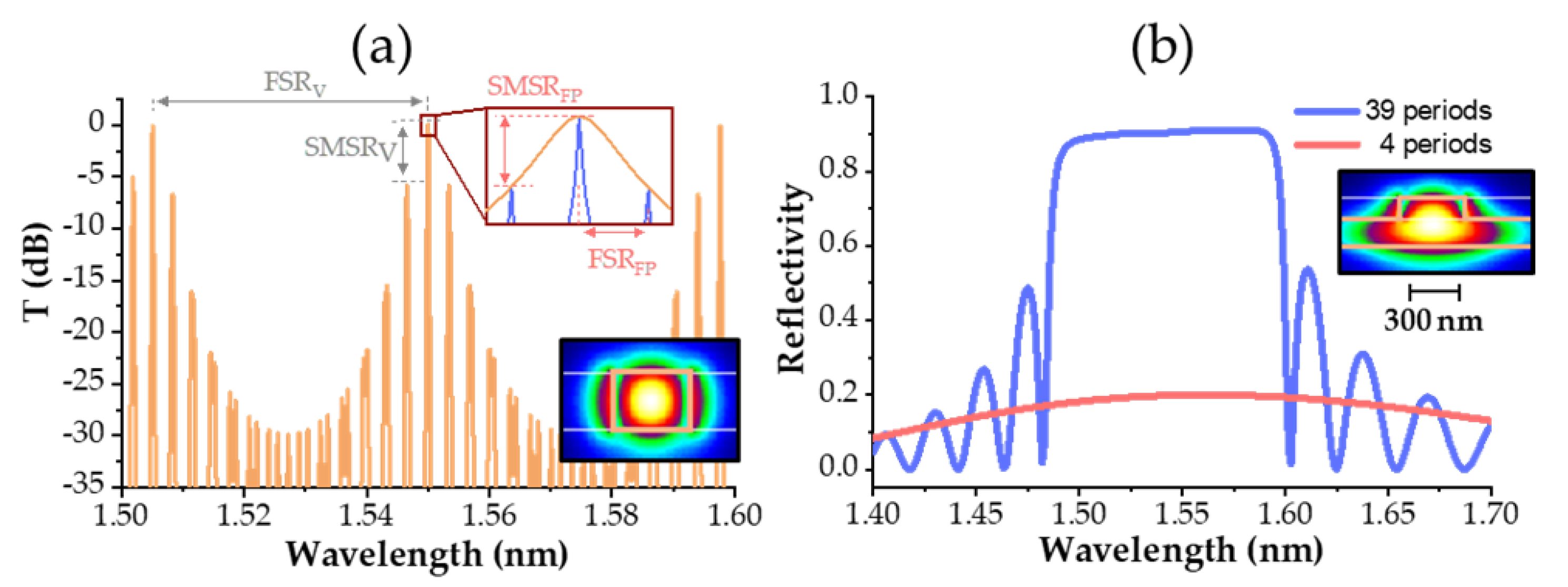
The ring-based Vernier filter has been designed in a 310 nm-thick SOI platform using strip waveguides. The inset below in Figure 2a shows an optical mode cross-section simulation of the fundamental TE-like mode. As seen, the optical mode is tightly confined in the waveguide, which allows designing compact photonic circuits with small bend radius. The Vernier filter is composed by two racetrack resonators coupled to a bus waveguide, each of them with a roundtrip length of 164.6 µm and 153.1 µm, respectively. Such parameters provide a theoretical, Vernier free spectral range (FSR) of 50 nm (see the grey horizontal arrow in Figure 2a). A careful optimization of the self-coupling coefficient (r) between the racetrack resonators and the bus waveguide was carried out to ensure single frequency operation of the widely tunable laser with a low insertion loss penalty. Too low r values would induce negligible insertion loss in the laser cavity, but at the price of a mitigated mode filtering that would derive in multimode unstable operation. To avoid that, the Vernier frequency response should have a sufficiently high side mode suppression ratio (SMSR) between its central lobe with maximum transmission and the adjacent transmission lobes with lower transmission (see the grey vertical arrow at the left-hand side of Figure 2a). In our case, we have defined a Vernier SMSRV of 6 dB. Moreover, the mode selectivity at the central lobe also plays an important role in rejecting adjacent longitudinal close-in modes. The upper inset of Figure 2a provides a zoom-in view of the Vernier’s spectral response around its maximum of transmission (orange trace) overlaid with the simulated longitudinal cavity mode spectrum, assuming an enhanced optical length at resonance (blue trace). As seen, the ability to filter out longitudinal close-in modes can also be evaluated with an SMSRFP parameter, which is around 5 dB in our widely tunable laser (see the vertical pale red arrow at the inset of Figure 2a). This value can be adjusted by either varying the FSR of the longitudinal cavity modes (for instance, by modifying the effective optical length of the cavity) or by narrowing (or widening) the half width at half maximum (HWHM) of the maximum transmission lobe. For the current design presented in this work, we have used a HWHM of 10.3 GHz and a longitudinal mode FSRFP of 13.3 GHz for a wavelength of 1549 nm. Thus, the lasing wavelength of the widely tunable laser is defined by the spectral positioning of such maximum transmission lobes, which is governed by the optical phase of the Vernier filter. In our design, we have used a couple of thermal heaters placed on top of each racetrack resonator to finely control such optical phases by means of the thermo-optic effect. Further details on the design of Vernier filters can be found in [22].
The optical feedback in the widely tunable laser cavity has been performed with two Bragg mirrors etched in a Si rib waveguide with a core height of 310 nm. Inset of Figure 2b shows the fundamental TE-like mode profile. The Si waveguide has a rib width of 2 µm, a slab width of 10 µm and rib height of 143 nm. Total internal reflection is obtained through a highly reflective Bragg mirror that is composed by 39 periods, has an etching depth of 40 nm, a duty cycle of 50% and a period of 276 nm. A second Bragg grating with lower reflectivity is placed at the laser’s output side. In this case, only four periods have been used. Figure 2b displays the simulated transmission of both components. The highly reflective Bragg mirror presents a spectrally flat reflectivity of 90% with a stop band of Δλ = 100 nm centered at λ = 1540 nm. For the output reflective Bragg mirror, we observe a reflectivity spectrum centered at the same wavelength with a maximum reflectivity of 20%, although it shows a much wider stop band that extends over a range of Δλ = 300 nm. In any case, only the wavelength range that overlaps with the optical gain bandwidth of the MQWs will be relevant for the laser design (typically from Δλ = 1500 nm to 1600 nm).
The co-integrated, widely tunable laser-SOA booster has been fabricated by wafer molecular bonding of a 100 mm III-V epilayer on a previously patterned 200 mm SOI wafer containing the Si photonic circuitry. A thin chemically polished silicon dioxide layer is used as a bonding interface. After InP substrate removal, III-V waveguides were patterned and cladded with a BCB polymer. Then, via definition and device metallization was carried out. A detailed description of the device fabrication can be found elsewhere [2,37]. Finally, the co-integrated device was cleaved at the SOA edge (see Figure 1). An anti-reflecting coating was deposited at the output facet to minimize optical back-reflections.

3. Experimental Results

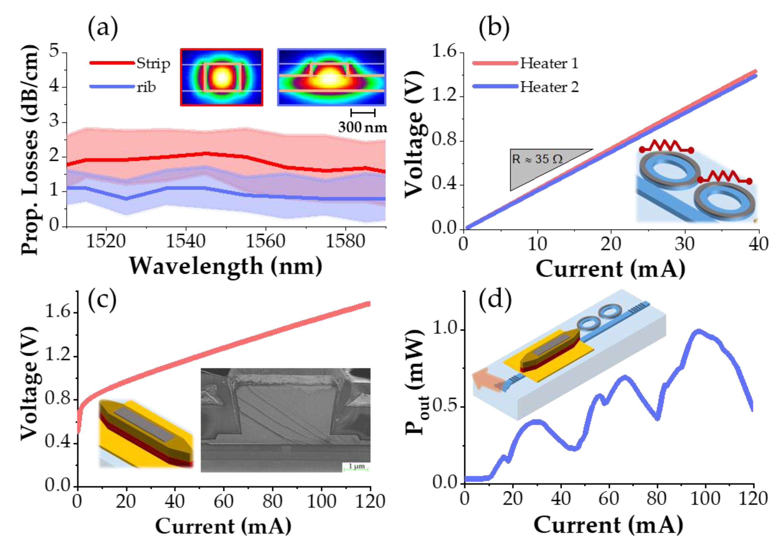
The co-integrated, widely tunable laser-SOA booster was mounted on a temperature-controlled holder set at T = 20 °C. Figure 3a shows the measured propagation losses as a function of the optical wavelength for strip and rib Si waveguides. Narrow lines represent the average value from 10 measured dies, and the colored area around them corresponds to the experimental deviation. Strip (rib) Si waveguides present an average propagation loss of 2 dB/cm (1 dB/cm) all over the measured wavelength range (λ = 1510 nm–1590 nm). Figure 3b represents the measured V-I response of thermal heaters, showing a similar series resistance of R ≈ 35 Ω and a reasonably low voltage. Indeed, ramping up the driving current of an individual heater to 30 mA (V < 1.2 V) is enough to induce a sweep in the laser’s emission wavelength up to half of the Vernier’s FSR (i.e., 25 nm). The remaining lasing wavelength is covered by the other thermal heater, which sweeps the emission wavelength in the opposite direction in the spectrum (one racetrack resonator induces a red shift and the other one a blue shift).
Figure 3c shows the V-I curve of the laser’s gain section (see the 3D schematic at the inset). We measure a differential resistance of 6 Ω, in agreement with the values reported elsewhere in similar devices [18,36]. To evaluate the output optical power of the widely tunable laser uniquely, P-I measurements were performed on equivalent tunable lasers de-coupled from the SOA booster. In this case, however, reflectionless vertical grating couplers were designed at the laser output to allow for on-chip characterization [38]. A cleaved fiber with an angle of 11.5° is used. The P-I characteristic for a laser emission wavelength around of λ = 1549 nm is shown in Figure 2d. A laser threshold of 10 mA (<1 kA/cm2) and a maximum fiber-coupled output power of 1 mW for an injected current of I = 100 mA were obtained. For higher injected currents, thermal roll-off quickly degrades the fiber-coupled optical power. Thus, assuming that the optical mode mismatch between the vertical grating coupler and the optical fiber induces 3 dB of coupling losses, we can consider a maximum on-chip coupled optical power around of 2 mW (3 dBm) in this standalone configuration. The kinks observed on the P-I curve correspond to longitudinal mode hopping in the cavity caused by localized Joule heating in the gain section as the current injection is increased. Such misalignment between the spectral transmission of the passive Vernier filter and the optical phase of the gain’s section can be suppressed by adding a phase shifter in the laser cavity to automatically readjust the optical cavity length [39].
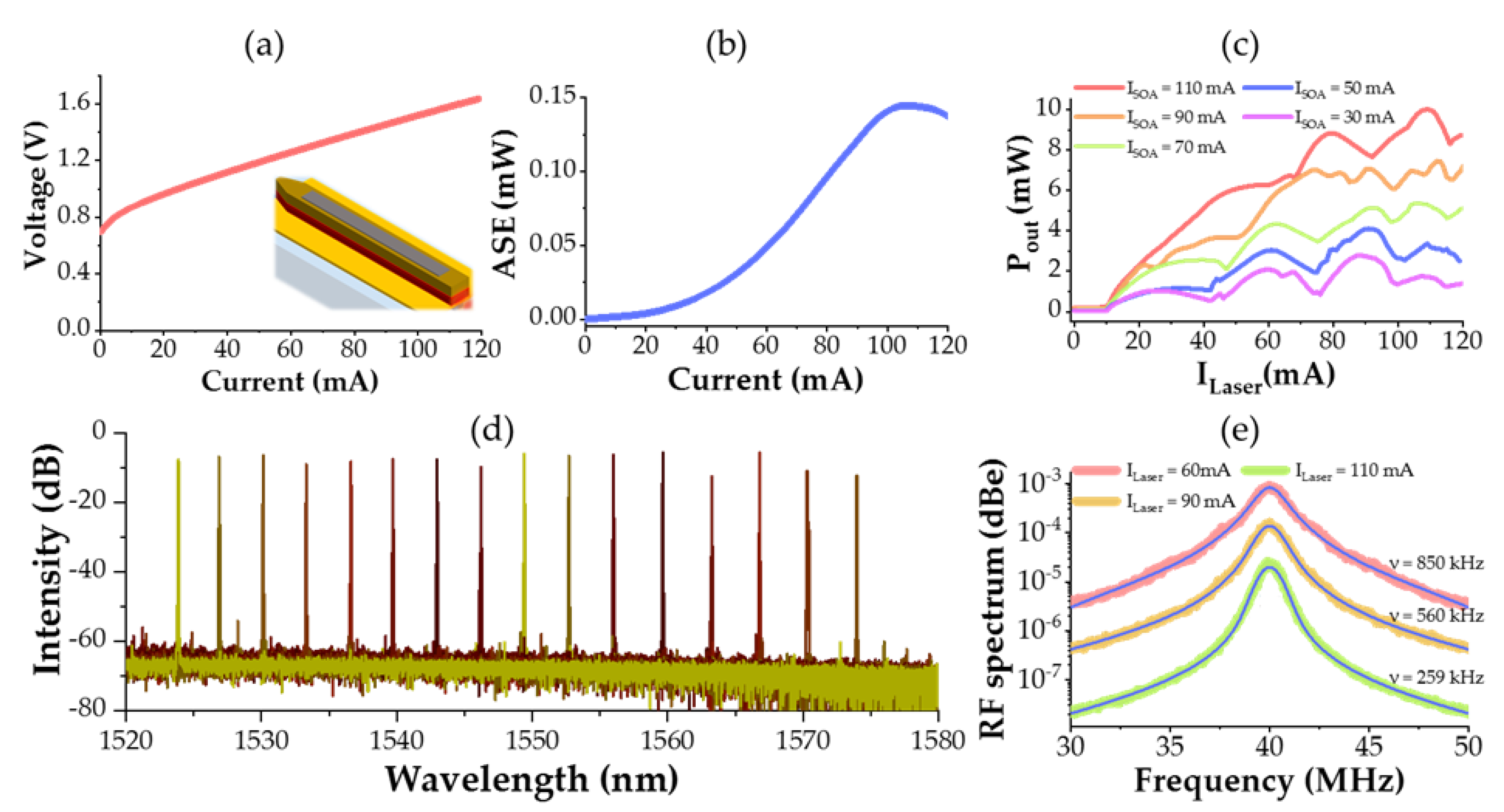
Similar to the widely tunable laser, the SOA booster has been first characterized independently. For that, we used the co-integrated system from Figure 1, characterizing the SOA-booster from its output facet while being the tunable laser in open circuit. The output power is measured in a butt-coupling configuration with a lensed fiber with a waist diameter of 3 µm, accounting 3 dB coupling losses. Figure 4a shows the V-I characteristic of the SOA-booster device. Similar to the tunable laser, we observe a differential resistance of 6 Ω and a similar voltage range. Figure 4b presents the amplified spontaneous emission (ASE) as a function of the injected current in the SOA booster. The curve peaks at I = 110 mA. It is worth remarking that no lasing emission was observed up to a current of I = 120 mA, which denotes the absence of significant back-reflections and, hence, validates the design of adiabatic tapers and the efficacy of the anti-reflection coating at the output facet. Figure 4c displays the fiber-coupled output power of the co-integrated system (y-axis) as a function of the injected current in the laser’s gain section (x-axis) and for different injected current values in the SOA booster. Each curve corresponds to a different driving current in the SOA, in steps of 20 mA up to 110 mA. Similar to the test widely tunable laser device, several kinks in the P-I curve, due to the passive-active phase mismatch, are seen. A consistent increase in the P-I curve is observed for consecutive values of injected current in the SOA booster, with a maximum of 10 mW (10 dBm) for an injected current of I = 110 mA in both the SOA and the laser’s gain section (see the peak value of the pale red curve). Bearing in mind that the butt-coupling configuration induces 3 dB of fiber coupling losses, this value corresponds to a waveguide-coupled optical power of 20 mW (13 dBm). From this value on, the fiber-coupled optical power quickly saturates and decreases steadily for higher SOA current values, denoting the kick-off of nonlinear and/or thermal effects. This observation is in agreement with the peak ASE value in Figure 4b. From this curve, we estimate an on-chip optical gain for the SOA of 10 dB, i.e., 18 dB/mm. This value is comparable with similar III-V/Si SOAs recently reported [40]. Figure 4d shows a superposition of the measured lasing spectra for different driving currents in the Vernier filter. A wavelength tuning range of 50 nm is obtained over a span from 1524 nm to 1574 nm, with a side-mode suppression ratio (SMSR) over 50 dB for the entire wavelength range.
To evaluate the coherence of our system, we have also measured its intrinsic linewidth. Figure 4e shows the measured RF spectrum of the co-integrated widely tunable laser-SOA booster device in a delayed self-heterodyne measurement using an acousto-optic modulation frequency of 40 MHz [41]. The measurement was performed with the SOA booster driven under optimum operation conditions, i.e., at ISOA = 110 mA, while increasing the laser current gradually from ILaser = 60 mA up to 110 mA (driving current for the maximum output power measured). Low-noise current sources were used to avoid spectral broadening of the laser linewidth due to current induced fluctuations. Technical noise is also another important factor that induces remarkable spectral distortion, especially at low frequency values, as it evolves as 1/f. As a consequence, the measured laser linewidth is often fitted with a pseudo-Voigt profile that accounts for the Lorentzian-like shape of the emitted signal and the Gaussian-like shape of the technical noise [22]. As can be observed, the increase in the laser’s driving current induces a consistent linewidth narrowing down to a minimum measured value of ν = 259 KHz for an injected driving current of ILaser = 110 mA. It is worth remarking that all measurements were performed under a negative optical feedback regime to reduce the laser linewidth spectral shape as much as possible. This regime, also called detuned loading, introduces an amplitude-phase coupling of the lasing field that enhances the stability of the laser frequency. To attain such regime, the laser optical frequency of the solitary mode should be slightly detuned (red-shifted) with respect to the frequency-dependent mirror reflectivity spectrum, reff(ω) [42]. Nonetheless, this method often provides an underestimation of the laser linewidth as it is very difficult to completely isolate the device under test from residual noise sources in the setup. Thus, the value of 259 KHz should be considered as an upper bound for the optical linewidth. Alternatively, one can use a direct frequency noise measurement to finely measure the laser linewidth [43]. Despite that, the measured Lorentzian linewidth with the self-delayed heterodyne method is in agreement with previously reported widely tunable lasers containing similar extended Si cavities, proving the good spectral purity of the co-integrated device. Thus, we can discard a remarkable laser linewidth broadening effect caused by an eventual ASE feedback from the SOA booster into the widely tunable laser.
The co-integrated widely tunable laser-SOA booster has a maximum power consumption of 420 mW when operating under the most power demanding conditions, i.e., with Ilaser = ISOA = 110 mA and with Iheater1 = Iheater2 = 30 mA. This value is reasonably low compared to other reported values on single III-V/Si devices [40,44]. Once more, the origin of such low power consumption is attributed to the high compactness of our widely tunable laser-SOA booster device.

4. Conclusions

We have demonstrated compact, low-threshold and high power widely tunable III-V/Si lasers co-integrated with semiconductor optical amplifiers. The device presents a laser current threshold of 10 mA, a fiber-coupled output power of 10 mW, a wavelength tuning range of 50 nm, and a total power consumption below 0.5 W. The spectral purity has been evaluated, obtaining a side mode suppression ratio over 50 dB for the entire wavelength range and a laser linewidth of 259 KHz when delivering its maximum output power.
The demonstrated co-integrated, widely tunable laser–SOA booster device can have a key role in applications where compact, low-threshold, high power, and narrow linewidth lasers are required, such as in coherent communications, LiDAR, coherent sensing, spectroscopy, or frequency synthesis. Future work on the co-integration of compact III-V/Si devices will focus on the inclusion of a high-speed electro-absorption modulator and on the improvement of the fiber-coupled optical power by using optimized edge couplers.

Author Contributions

J.M.R. contributed to the wafer level and chip-on-carrier characterization, methodology, formal analysis, data curation, simulation, and writing/original draft preparation. P.F.d.l.H. contributed to review and editing. J.-G.P. contributed to methodology, chip-on-carrier characterization, review, and editing. S.M. contributed to SOI fabrication. D.N. contributed to III-V fabrication, simulation, review, and editing. C.J. contributed to III-V fabrication. C.B., N.V., and J.D. contributed to III-V epitaxy, review, and editing. K.H. contributed to wafer level characterization, review, and editing. D.B. contributed to simulations, formal analysis, review, and editing. All authors have read and agreed to the published version of the manuscript.

Funding

The authors acknowledge funding from the European program H2020 (Medphab) N° 871345 and from the french economic and financial department through the program Nano 2022-IPCEI.

Institutional Review Board Statement

Not applicable.

Informed Consent Statement

Not applicable.

Data Availability Statement

Not applicable.

Acknowledgments

The authors would like to thank P. Charbonnier, H. Gariah, D. Make, F. Blache, V. Muffato, C. Rostaing et J. Dafonseca for their technical support and useful discussions. All data supporting this review paper is openly available from the III-V lab repository at R&D Activities (3-5lab.fr).

Conflicts of Interest

The authors declare no conflict of interest. The funders had no role in the design of the study; in the collection, analyses, or interpretation of data; in the writing of the manuscript; or in the decision to publish the results.

References

  1. Roelkens, G.; Liu, L.; Liang, D.; Jones, R.; Fang, A.; Koch, B.; Bowers, J. III-V/silicon photonics for on-chip and intra-chip optical interconnects. Laser Photonics Rev. 2010, 4, 751–779. [Google Scholar] [CrossRef]
  2. Duan, G.-H.; Jany, C.; Le Liepvre, A.; Accard, A.; Lamponi, M.; Make, D.; Kaspar, P.; Levaufre, G.; Girard, N.; Lelarge, F.; et al. Hybrid III–V on Silicon Lasers for Photonic Integrated Circuits on Silicon. IEEE J. Sel. Top. Quantum Electron. 2014, 20, 158–170. [Google Scholar] [CrossRef] [Green Version]
  3. Marpaung, D.; Yao, J.; Capmany, J. Integrated microwave photonics. Nat. Photonics 2019, 13, 80–90. [Google Scholar] [CrossRef]
  4. Pérez, D.; Gasulla, I.; Crudgington, L.; Thomson, D.J.; Khokhar, A.Z.; Li, K.; Cao, W.; Mashanovich, G.Z.; Capmany, J. Multipurpose silicon photonics signal processor core. Nat. Commun. 2017, 8, 636. [Google Scholar] [CrossRef] [PubMed] [Green Version]
  5. Poulton, C.V.; Yaacobi, A.; Cole, D.B.; Byrd, M.J.; Raval, M.; Vermeulen, D.; Watts, M.R. Coherent solid-state lidar with silicon photonic optical phased arrays. Opt. Lett. 2017, 42, 4091–4094. [Google Scholar] [CrossRef] [PubMed]
  6. Xie, W.; Komljenovic, T.; Huang, J.; Tran, M.; Davenport, M.; Torres, A.; Pintus, P.; Bowers, J. Heterogeneous silicon photonics sensing for autonomous cars [Invited]. Opt. Express 2019, 27, 3642–3663. [Google Scholar] [CrossRef]
  7. Davenport, M.L.; Skendzic, S.; Volet, N.; Hulme, J.C.; Heck, M.J.R.; Bowers, J.E. Heterogeneous Silicon/III–V Semiconductor Optical Amplifiers. IEEE J. Sel. Top. Quantum Electron. 2016, 22, 78–88. [Google Scholar] [CrossRef]
  8. Tang, M.; Park, J.-S.; Wang, Z.; Chen, S.; Jurczak, P.; Seeds, A.; Liu, H. Integration of III-V lasers on Si for Si photonics. Prog. Quantum Electron. 2019, 66, 1–18. [Google Scholar] [CrossRef]
  9. Dong, P.; Chen, Y.-K.; Duan, G.-H.; Neilson, D.T. Silicon photonic devices and integrated circuits. Nanophotonics 2014, 3, 215–228. [Google Scholar] [CrossRef]
  10. Guo, X.; He, A.; Su, Y. Recent advances of heterogeneously integrated III–V laser on Si. J. Semicond. 2019, 40, 101304. [Google Scholar] [CrossRef]
  11. Ramirez, J.M.; Malhouitre, S.; Gradkowski, K.; Morrissey, P.E.; O’Brien, P.; Caillaud, C.; Vaissiere, N.; Decobert, J.; Lei, S.; Enright, R.; et al. III-V-on-Silicon Integration: From Hybrid Devices to Heterogeneous Photonic Integrated Circuits. IEEE J. Sel. Top. Quantum Electron. 2019, 26, 1–13. [Google Scholar] [CrossRef]
  12. Matsumoto, T.; Kurahashi, T.; Konoike, R.; Suzuki, K.; Tanizawa, K.; Uetake, A.; Takabayashi, K.; Ikeda, K.; Kawashima, H.; Akiyama, S.; et al. Hybrid-Integration of SOA on Silicon Photonics Platform Based on Flip-Chip Bonding. J. Light. Technol. 2018, 37, 307–313. [Google Scholar] [CrossRef]
  13. Verdier, A.; de Valicourt, G.; Brenot, R.; Debregeas, H.; Dong, P.; Earnshaw, M.; Carrère, H.; Chen, Y. Ultrawideband wavelength-tunable hybrid external-cavity lasers. J. Light. Technol. 2017, 36, 37–43. [Google Scholar] [CrossRef]
  14. Han, Y.; Yan, Z.; Ng, W.K.; Xue, Y.; Wong, K.S.; Lau, K.M. Bufferless 1.5 µm III-V lasers grown on Si-photonics 220 nm silicon-on-insulator platforms. Optica 2020, 7, 148–153. [Google Scholar] [CrossRef]
  15. Justice, J.; Bower, A.C.; Meitl, M.; Mooney, M.B.; Gubbins, M.A.; Corbett, B. Wafer-scale integration of group III–V lasers on silicon using transfer printing of epitaxial layers. Nat. Photonics 2012, 6, 610–614. [Google Scholar] [CrossRef]
  16. Zhang, J.; Muliuk, G.; Juvert, J.; Kumari, S.; Goyvaerts, J.; Haq, B.; Op De Beeck, C.; Kuyken, B.; Morthier, G.; Van Thourhout, D.; et al. III-V-on-Si photonic integrated circuits realized using micro-transfer-printing. APL Photonics 2019, 4, 110803. [Google Scholar] [CrossRef] [Green Version]
  17. Szelag, B.; Hassan, K.; Adelmini, L.; Ghegin, E.; Rodriguez, P.; Nemouchi, F.; Brianceau, P.; Vermande, E.; Schembri, A.; Carrara, D.; et al. Hybrid III–V/Silicon Technology for Laser Integration on a 200-mm Fully CMOS-Compatible Silicon Photonics Platform. IEEE J. Sel. Top. Quantum Electron. 2019, 25, 1–10. [Google Scholar] [CrossRef]
  18. Fang, A.W.; Park, H.; Cohen, O.; Jones, R.; Paniccia, M.J.; Bowers, J.E. Electrically pumped hybrid AlGaInAs-silicon evanescent laser. Opt. Express 2006, 14, 9203–9210. [Google Scholar] [CrossRef] [PubMed]
  19. Park, H.; Fang, A.W.; Cohen, O.; Jones, R.; Paniccia, M.J.; Bowers, J.E. A Hybrid AlGaInAs–Silicon Evanescent Amplifier. IEEE Photonics Technol. Lett. 2007, 19, 230–232. [Google Scholar] [CrossRef]
  20. Keyvaninia, S.; Verstuyft, S.; van Landschoot, L.; Lelarge, F.; Duan, G.-H.; Messaoudene, S.; Fedeli, J.M.; de Vries, T.; Smalbrugge, B.; Geluk, E.J.; et al. Heterogeneously integrated III-V/silicon distributed feedback lasers. Opt. Lett. 2013, 38, 5434–5437. [Google Scholar] [CrossRef] [Green Version]
  21. Kaspar, P.; De Valicourt, G.; Brenot, R.; Mestre, M.A.; Jennevé, P.; Accard, A.; Make, D.; Lelarge, F.; Duan, G.-H.; Pavarelli, N.; et al. Hybrid III-V/Silicon SOA in Optical Network Based on Advanced Modulation Formats. IEEE Photonics Technol. Lett. 2015, 27, 2383–2386. [Google Scholar] [CrossRef]
  22. Tran, M.A.; Huang, D.; Bowers, J.E. Tutorial on narrow linewidth tunable semiconductor lasers using Si/III-V heterogeneous integration. APL Photonics 2019, 4, 111101. [Google Scholar] [CrossRef] [Green Version]
  23. Yamaoka, S.; Diamantopoulos, N.; Nishi, H.; Nakao, R.; Fujii, T.; Takeda, K.; Hiraki, T.; Tsurugaya, T.; Kanazawa, S.; Tanobe, H.; et al. Directly modulated membrane lasers with 108 GHz bandwidth on a high-thermal-conductivity silicon carbide substrate. Nat. Photonics 2021, 15, 28–35. [Google Scholar] [CrossRef]
  24. Wan, Y.; Xiang, C.; Guo, J.; Koscica, R.; Kennedy, M.; Selvidge, J.; Zhang, Z.; Chang, L.; Xie, W.; Huang, D.; et al. High Speed Evanescent Quantum-Dot Lasers on Si. Laser Photonics Rev. 2021, 15, 2100057. [Google Scholar] [CrossRef]
  25. Jones, R.; Doussiere, P.; Driscoll, J.B.; Lin, W.; Yu, H.; Akulova, Y.; Komljenovic, T.; Bowers, J.E. Heterogeneously Integrated InP\/Silicon Photonics: Fabricating Fully Functional Transceivers. IEEE Nanotechnol. Mag. 2019, 13, 17–26. [Google Scholar] [CrossRef]
  26. Liang, D.; Labs, H.P.E.H.P.; Bowers, J.E. Recent Progress in Heterogeneous III-V-on-Silicon Photonic Integration. Light. Adv. Manuf. 2021, 2, 59–83. [Google Scholar] [CrossRef]
  27. Shang, C.; Wan, Y.; Selvidge, J.; Hughes, E.; Herrick, R.; Mukherjee, K.; Duan, J.; Grillot, F.; Chow, W.W.; Bowers, J.E. Perspectives on Advances in Quantum Dot Lasers and Integration with Si Photonic Integrated Circuits. ACS Photonics 2021, 8, 2555–2566. [Google Scholar] [CrossRef]
  28. Zhang, S.J.; Liu, Y.; Lu, R.G.; Sun, B.; Yan, L.S. Heterogeneous III–V silicon photonic integration: Components and characterization. Front. Inf. Technol. Electron. Eng. 2019, 20, 472–480. [Google Scholar] [CrossRef]
  29. Haq, B.; Kumari, S.; van Gasse, K.; Zhang, J.; Gocalinska, A.; Pelucchi, E.; Corbett, B.; Roelkens, G. Micro-Transfer-Printed III-V-on-Silicon C-Band Semiconductor Optical Amplifiers. Laser Photonics Rev. 2020, 14, 1900364. [Google Scholar] [CrossRef]
  30. Komljenovic, T.; Huang, D.; Pintus, P.; Tran, M.A.; Davenport, M.L.; Bowers, J.E. Photonic integrated circuits using heterogeneous integration on silicon. Proc. IEEE 2018, 106, 2246–2257. [Google Scholar] [CrossRef]
  31. Margalit, N.; Xiang, C.; Bowers, S.M.; Bjorlin, A.; Blum, R.; Bowers, J.E. Perspective on the future of silicon photonics and electronics. Appl. Phys. Lett. 2021, 118, 220501. [Google Scholar] [CrossRef]
  32. Bao, S.; Wang, Y.; Lina, K.; Zhang, L.; Wang, B.; Sasangka, W.A.; Lee, K.E.K.; Chua1, S.J.; Michel, J.; Fitzgerald, E. A review of silicon-based wafer bonding processes, an approach to realize the monolithic integration of Si-CMOS and III–V-on-Si wafers. J. Semicond. 2021, 42, 023106. [Google Scholar] [CrossRef]
  33. Zhao, B.; Chen, T.R.; Yariv, A. The extra differential gain enhancement in multiple-quantum-well lasers. IEEE Photonics Technol. Lett. 1992, 4, 124–126. [Google Scholar] [CrossRef] [Green Version]
  34. Morito, K.; Tanaka, S.; Tomabechi, S.; Kuramata, A. A broad-band MQW semiconductor optical amplifier with high saturation output power and low noise figure. IEEE Photonics Technol. Lett. 2005, 17, 974–976. [Google Scholar] [CrossRef]
  35. Arakawa, Y.; Yariv, A. Quantum well lasers–Gain, spectra, dynamics. IEEE J. Quantum Electron. 1986, 22, 1887–1899. [Google Scholar] [CrossRef] [Green Version]
  36. Coldren, L.A.; Corzine, S.W.; Mashanovitch, M.L. Diode Lasers and Photonic Integrated Circuits; John Wiley & Sons: Hoboken, NJ, USA, 2012; Volume 218. [Google Scholar]
  37. Keyvaninia, S.; Roelkens, G.G.; Van Thourhout, D.; Jany, C.; Lamponi, M.; Le Liepvre, A.; Lelarge, F.; Make, D.; Duan, G.-H.; Bordel, D.; et al. Demonstration of a heterogeneously integrated III-V/SOI single wavelength tunable laser. Opt. Express 2013, 21, 3784–3792. [Google Scholar] [CrossRef] [PubMed] [Green Version]
  38. Fowler, D.; Grosse, P.; Gays, F.; Szelag, B.; Baudot, C.; Vuillet, N.; Planchot, J.; Boeuf, F. Fiber grating coupler development for Si-photonics process design kits at CEA-LETI. In Smart Photonic and Optoelectronic Integrated Circuits XXI; International Society for Optics and Photonics: Bellingham, DC, USA, 2019; Volume 10922, p. 109225. [Google Scholar]
  39. Boller, Y.K.; van Rees, A.; Fan, Y.; Mak, J.; Lammerink, R.E.M.; Franken, C.A.A.; van der Slot, P.J.M.; Marpaung, D.A.I.; Fallnich, C.; Epping, J.P. Hybrid integrated semiconductor lasers with silicon nitride feedback circuits. Photonics 2020, 7, 4. [Google Scholar] [CrossRef] [Green Version]
  40. Van Gasse, K.; Wang, R.; Roelkens, G. 27 dB gain III–V-on-silicon semiconductor optical amplifier with >17 dBm output power. Opt. Express 2019, 27, 293–302. [Google Scholar] [CrossRef] [Green Version]
  41. Dawson, J.W.; Park, N.; Vahala, K.J. An improved delayed self-heterodyne interferometer for linewidth measurements. IEEE Photonics Technol. Lett. 1992, 4, 1063–1066. [Google Scholar] [CrossRef] [Green Version]
  42. Vahala, K.; Yariv, A. Detuned loading in coupled cavity semiconductor lasers—Effect on quantum noise and dynamics. Appl. Phys. Lett. 1984, 45, 501. [Google Scholar] [CrossRef] [Green Version]
  43. Sorin, W.; Chang, K.; Conrad, G.; Hernday, P. Frequency domain analysis of an optical FM discriminator. J. Light. Technol. 1992, 10, 787–793. [Google Scholar] [CrossRef]
  44. Le Liepvre, A.; Jany, C.; Accard, A.; Lamponi, M.; Poingt, F.; Make, D.; Lelarge, F.; Fedeli, J.-M.; Messaoudene, S.; Bordel, D.; et al. Widely wavelength tunable hybrid III–V/silicon laser with 45 nm tuning range fabricated using a wafer bonding technique. In Proceedings of the 9th International Conference on Group IV Photonics (GFP), San Diego, CA, USA, 29–31 August 2012; pp. 54–56. [Google Scholar]
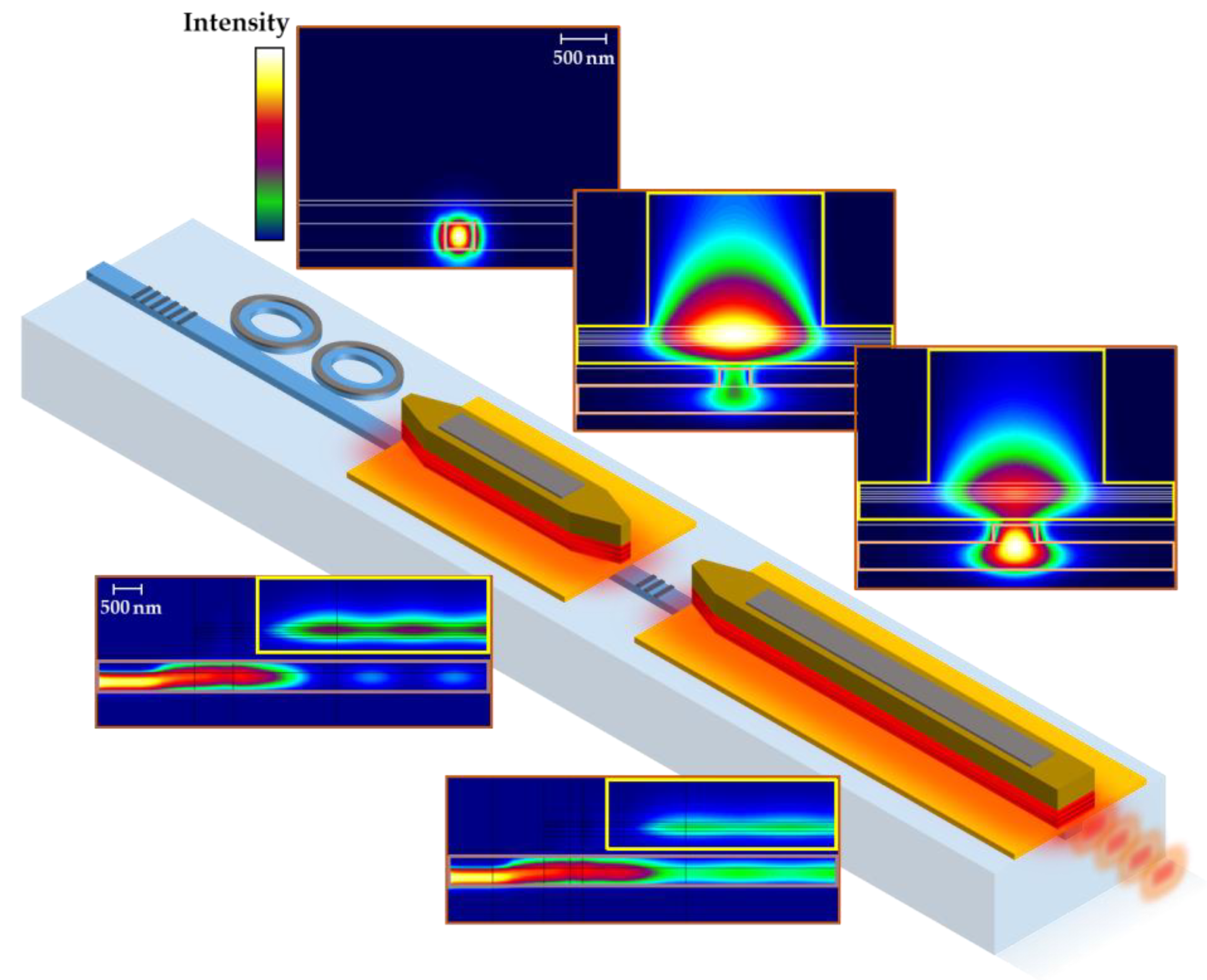
Figure 1. 3D schematic view of the co-integrated, tunable laser-SOA booster. From left to right: the highly reflective Bragg mirror; the Vernier filter; the III-V gain section of the laser; the low reflective Bragg mirror; the III-V gain section of the SOA booster; and the output facet for fiber coupling. The upper insets show the fundamental TE-like mode cross-section for the ring-based Vernier filter (left), the tunable laser (middle), and the SOA booster (right). The insets below show the fundamental TE-like mode propagation in the laser (left) and in the SOA booster (right).
Applsci 11 11096 g001
Figure 2. (a) Simulated Vernier filter transmission for a wavelength range from λ = 1500–1600 nm. The upper inset shows a zoom-in view around one of the Vernier’s maximum transmission lobes (orange trace) overlaid with the simulated longitudinal mode spectrum of the laser cavity (blue trace). The inset below shows a cross-section optical mode simulation of the Si waveguide Vernier filter. (b) Simulated reflectivity spectrum of the Bragg mirror with 39 periods (blue trace) and with four periods (pale red trace). The inset shows a cross-section optical mode simulation of the Si waveguide Bragg mirror.
Applsci 11 11096 g002
Figure 3. (a) Propagation losses of the strip (red trace) and rib (blue trace) Si waveguides as a function of the optical wavelength. Colored zones correspond to the experimental deviation from the average value. Insets show the fundamental TE-like mode simulation for the strip (left) and the rib (right) waveguides. (b,c) present the V-I characteristic of the thermal heaters of the Vernier filter and the laser’s gain section. (d) P-I curve of a test widely tunable laser device containing a vertical grating coupler output. Insets in (bd) show 3D schematic views of each device and an SEM cross-section view of the laser’s gain section.
Applsci 11 11096 g003
Figure 4. (a) V-I characteristic of the SOA booster. (b) Fiber-coupled ASE optical power in function of the SOA injected current. (c) P-I curves of the widely tunable laser for different driving current values in the SOA booster, in steps of 20 mA. (d) Overlaid spectra of the co-integrated device. Each spectrum corresponds to a different driving operation point at the Vernier filter. (e) Measured RF delayed self-heterodyne spectrum for different driving current values in the widely tunable laser (for a single ISOA = 110 mA). Blue traces correspond to the Voigt fitting used to extract the laser linewidth. The curves have been up-shifted for convenience.
Applsci 11 11096 g004
Publisher’s Note: MDPI stays neutral with regard to jurisdictional claims in published maps and institutional affiliations.