Abstract
The design of steel chevron-braced frames as per Eurocode 8 is based on the idea that only the braces should buckle and yield during ground motions, while other members should remain elastic. The elastic design of the braced frames is also allowed. However, in both cases, the seismic performance of the frame may be compromised because of premature yielding/buckling of columns. This paper proposes an alternative design procedure that promotes yielding of beams in addition to yielding of braces. This mitigates the vertical unbalanced force transmitted by compressive and tensile braces to the beam and in turn reduces the internal forces of the columns. The result is the overall improvement of the seismic performance owing to the reduction of the number of cases in which failure of the columns occurs before full exploitation of the ductility capacity of the dissipative members. The proposed design procedure is validated by incremental dynamic analyses performed on a set of chevron-braced frames. In particular, the peak ground accelerations of the frames designed by the proposed procedure at the attainment of Significant Damage and Collapse Prevention limit states are determined and compared to those of frames designed according to Eurocode 8. Furthermore, frames designed according to the Eurocodes and to the proposed method are compared in terms of structural cost.
1. Introduction
Chevron-braced frames have been widely investigated by the scientific community. Studies on these structures were intended either to (i) examine the cyclic response of the brace; (ii) assess the dynamic response of braced structures designed according to seismic codes; or (iii) propose alterative design procedures.
Regarding the first issue, experimental activities were carried on braces with a different slenderness and cross-section shape [1,2,3,4] to evaluate their cyclic behaviour and axial displacement capacity [5]. In this regard, the displacement capacity is expressed as a function of the slenderness of the brace, cross-section aspect ratio and width-to-thickness ratio. Conversely, the displacement demand to be compared to the displacement capacity has been expressed as a function of either the cumulated tensile ductility demand of the brace [6], the cumulated ductility demand in tension and compression [7] or the sum of the maximum ductility demands in tension and compression [8]. A different approach was followed in [9,10], where the displacement capacity is predicted considering the low-cycle fatigue in the numerical model of the brace.
Regarding the second issue, some studies have been carried out to compare the effectiveness of the design procedures included in the European, North American and Canadian seismic codes in ensuring ductile collapse mechanisms [11,12]. Other studies have been focused instead on the evaluation of the impact of design provisions on the response of chevron-braced frames [13,14,15]. In particular, these studies pointed out the need of ensuring an adequate flexural stiffness of the beam of the braced frame and that the out-of-plane buckling of columns often occurs when analysing the response of structures designed according to the European seismic code [16].
Regarding the third issue, authors have proposed procedures for the design of chevron-braced frames. However, the majority of these design procedures can be attributed to three main approaches. In the following section, the leading ideas of the different design approaches/methods are briefly described, mainly focusing on the design of braces, beams and columns. Based on an analysis of features and the shortcomings of these approaches, a new design method is formulated, proposed and investigated in the paper.
2. Seismic Design of Steel Chevron-Braced Frames in Literature
2.1. Conventional Approach with a Buckling-Brace/Yielding-Brace Plastic Mechanism
The most common approach for the design of chevron-braced frames assumes that the inelastic response should be limited to the braces [16,17,18,19]. Based on this concept, braces are designed to sustain the internal forces determined by the selected elastic method of analysis, so as to provide an almost uniform distribution of overstrength along the height of the building, whereas beams and columns are designed according to the capacity design principle. Design procedures suggested in the literature or seismic codes, however, differ because of the recommended behaviour factor, because of the definition of the lateral storey strength provided by the braces and because of the rules for the application of design capacity principles.
Eurocode 8 (EC8) [16] requires that the axial forces determined by the design method of analysis in beams and columns be incremented by a scaling factor equal to 1.1 γov Ωmin. This scaling factor takes into account the overstrength and the hardening of steel (1.1 γov) and the minimum overstrength of the braces (Ωmin). This latter overstrength is defined as the minimum ratio of the buckling resistance to the axial force of braces among all storeys of the building. In addition, the braced beam, i.e., the beam where the chevron braces meet, has to sustain the bending moment produced by the unbalanced vertical force transmitted at midspan by the braces when the brace in compression is in the post-buckling range of behaviour and the brace in tension has yielded. Since beams and columns are designed according to the capacity design, no specific requirement is provided to guarantee a ductile behaviour of these members. Unfortunately, research studies [20,21] have proved that these simplified rules for the application of capacity design principles reported in Eurocode 8 are not effective in preventing the buckling of columns and yielding of the braced beams.
To estimate the axial forces in columns more accurately, Marino [22] proposed to evaluate these internal forces by equilibrium conditions based on two different design situations. In the first situation, axial forces in compressed braces are supposed to be equal to the buckling resistance, while the braces in tension have not yielded yet; in the second situation, braces in tension have yielded and are fully hardened, whereas braces in compression are in the post-buckling range of behaviour.
According to Costanzo et al. [18], the braces of the top storey should be designed to perform in the elastic range of behaviour. Owing to this, the top storey can act as an outrigger system, giving the building a “shear type” displacement profile. Columns are designed to resist the internal forces derived by two combinations of axial forces in braces. In the first combination, the axial forces are calculated according to EC8. However, differently from EC8, the minimum overstrength of the braces is calculated based on the plastic resistance of braces rather than on the buckling resistance. In the second combination, axial forces are calculated via equilibrium conditions, assuming that the braces in tension have yielded and the braces in compression are in their post-buckling range of behaviour. Moreover, in this latter combination, columns are assumed to be subjected to a bending moment equal to 20% of the plastic flexural resistance of the cross sections. Finally, to promote a more dissipative behaviour of braces, a beam stiffness requirement is proposed, suggesting that the beam-to-brace stiffness ratio should be greater than 0.2.
Barbagallo et al. [19] showed that the lateral torsional buckling of columns was the predominant failure mode of concentrically braced frames designed by the abovementioned procedures because of the underestimation of the bending moment in columns. Based on this, the authors proposed a new design procedure where an analytical equation was introduced to predict the bending moments in columns. Further, a stiffness requirement for beams and columns was formulated.
2.2. Approach with a Buckling-Brace/Yielding-Beam Plastic Mechanism
With the aim of reducing the structural costs of concentrically braced frames, some researchers have proposed a design approach that allows yielding of beams [23,24]. Yielding of the braced beams precludes yielding of the brace in tension and this shifts the braced frame from a buckling-brace/yielding-brace plastic mechanism to a buckling-brace/yielding-beam plastic mechanism. Two design situations are considered for the design of the braced beams. In the first situation, both the brace in tension and the brace in compression are subjected to a force equal to the buckling resistance. This situation leads to the maximum axial force in beams. The beam is designed to sustain this axial force, and this ensures that the braces in compression can buckle. In the second design situation, the brace in compression is in the post-buckling range of behaviour, whereas the axial force in the brace in tension is equal to the buckling resistance. In this situation, the braced beams are subjected to combined effects of axial force and bending moments. However, the considered bending moments are significantly lower than those arising from the conventional approach illustrated in Section 2.1.
2.3. Non Dissipative Approach with All Members in Elastic Range of Behaviour
Even if EC8 stipulates a design procedure for the design of concentrically braced frames and provides a maximum value of the behaviour factor to be adopted, the same seismic code allows the design of chevron bracings assuming an almost elastic behaviour. In such a case, a behaviour factor q as close as possible to 1.0 has to be used. In common practice, a behaviour factor equal to 1.5 is adopted, so that only minor damage is expected at the design level.
If such an approach is followed, the cross-section of braces can be selected without any attention to the distribution of the overstrength along the height of the building. Furthermore, beams and columns of the braced frames can be designed based on the internal forces obtained by means of the selected elastic method of analysis; i.e., it is not required to apply capacity design principles.
3. Proposed Design Approach
In this paper, a design procedure is proposed for chevron-braced frames located in low-seismicity areas.
The procedure does not require the application of capacity design provisions. Consistently, yielding of the braced beam due to the unbalanced vertical force caused by the braces is accepted. This yielding is expected to have a beneficial effect on the behaviour of the columns because it limits the axial forces transmitted to the columns of the braced bays.
Since the capacity design is not applied, a behaviour factor equal to 1.5 is considered.
3.1. Design of the Braces
Internal axial forces in braces are calculated as the sum of the axial forces due to gravity loads in the seismic design situation (NEd,G) and the axial forces determined by the elastic method of analysis assuming a behaviour factor equal to 1.5 (NEd,E).
Based on the study by Costanzo et al. [18], the braces of the top storey are designed to perform in the elastic range of behaviour (Equation (1)) whereas the cross-section area of the braces of the other storeys is selected so that the buckling resistance is higher than the design internal force (Equation (2)); i.e.,
where n is the number of storeys. Further, to avoid very slender braces, the normalized slenderness should be lower than 2.0. Since a low ductility is considered, brace cross-sections should be classified as Class 1 (highly ductile) or Class 2 (moderately ductile) according to Eurocode 3 (EC3) [25], but no specific requirement is provided with regard to the heightwise distribution of the brace overstrength.
Nb,Rd,n ≥ NEd,G,n + 1.5 NEd,E,n
Nb,Rd,i ≥ NEd,G,i + NEd,E,i i = 1 to n − 1
3.2. Design of the Braced Beams
When the braces are in the elastic range of behaviour, the braced beam is subjected to the axial force (NEd,b) produced by the seismic loads and shear forces (VEd,G,b) and the bending moments (MEd,G,b) produced by the gravity loads in the seismic design situation.
After buckling of the brace in compression, the braced beam is subjected to an unbalanced vertical force. The proposed procedure admits yielding of the beam under the bending moments produced by this force. Thus, a moderately ductile behaviour of this member is required. For this reason,
- a cross section classified as Class 1 or Class 2 has to be selected;
- the axial force in beams has to be lower than 0.3 times the plastic axial resistance.
Further, flexible braced beams sustain large deflection under the unbalanced vertical force transmitted by braces. In turn, this promotes the large inelastic deformation demand of the brace in compression, which is a premise for the premature fracture of the brace. To prevent this unfavourable yielding mechanism, the axial shortening δb of the braces caused by the vertical displacement produced at midspan of the beam by the unbalanced vertical force should be lower than a rate k of the axial displacement capacity of the brace (δu):
δb ≤ k δu
This study investigates different values for the coefficient k, namely, 0.2, 0.6, 1.0, 1.4 and 1.8.
Under the hypothesis of pinned beam-to-column connections, the axial shortening δb of the braces caused by the vertical displacement at midspan of the beam is calculated as
where Npl,br and Nu,br are the plastic and ultimate resistances of the brace, Es is the elastic modulus of steel, Ib is the moment of inertia of the beam, L is the length of the braced bay and α is the slope of the brace to the horizontal axis. In the equation above, the plastic resistance of the brace in tension is amplified by 1.1 to take into account the effect of hardening.
Parameter δu is calculated here as the elongation of the brace at yield δy times the ductility capacity of the brace at fracture μf, evaluated according to Marino [22] as
where θf is the rotation of the plastic hinge at mid-length of the brace at fracture. This capacity is calculated by the relation proposed by Tremblay [8] for HSS cross-sections and depends on the slenderness λ of the brace and on the cross-section shape by the width-to-thickness (b0/t) and depth-to-thickness (d0/t) ratios:
3.3. Design of Columns
Columns of the braced frames are subjected to axial forces and bending moments. Since an elastic design procedure is considered here, bending moments are neglected and axial forces are evaluated as the sum of the axial contribution due to gravity loads and the contribution due to seismic forces as determined by the design method of analysis. The column cross-section and steel grade are chosen so that the buckling resistance (determined assuming a column effective length factor equal to 1) is larger than the design internal force.
4. Case Study
The proposed design procedure has been applied to design a 4-storey and an 8-storey residential building endowed with braces in the chevron configuration. The plan layout of the buildings is shown in Figure 1. The length L of each bay is equal to 8.0 m, whereas the interstorey height h is equal to 4.0 m. The buildings stand on stiff soil (soil A according to EC8) and are located in a seismic area with a peak ground acceleration (ag) equal to 0.15 g. Based on the values of ag provided by the National Institute of Geophysics and Volcanology (IGNV [26]), this value is larger than that expected for seismic events with a probability of exceedance of 10% in 50 years in the 73.1% of the entire Italian territory.
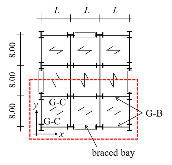
Figure 1.
Layout of the considered structures.
The seismic loads are entirely resisted by the braced bays that are located in the central span of the perimetric frames. Beams and columns denoted as G-B and G-C in Figure 1 are designed to sustain gravity loads only. Geometric and mass properties are assumed to be equal at all storeys. The characteristic values of gravity dead (gk) and live (qk) loads are equal to 4.4 kN/m2 and 2.0 kN/m2, respectively. Specifically, the dead load was derived assuming that the weight of the collaborating steel sheet is equal to 1.91 kN/m2, the weight of the suspended ceilings is equal to 0.40 kN/m2, the weight of screed is equal to 0.84 kN/m2, the weight of the floor porcelain stoneware is equal to 0.44 kN/m2 and the weight of the internal partitions is equal to 0.8 kN/m2. The characteristic value of the live load is that given in Eurocode 1 [27] for category of use type A (areas for residential activities).
Gravity loads in the seismic design situation (gk + ψ2qk) are equal to 5.0 kN/m2. Internal forces are determined by means of a modal response spectrum analysis. To optimize the design, an iterative procedure is adopted. HSS cross-sections with steel grade S355 (characteristic value of yield stress fy equal to 355 MPa) are used for the braces and wide flange cross-sections are used for the braced beams (HEA with steel grade S235) and columns (HEB, HEM with steel grade S235, S275 or S355). IPE cross-sections are used for the beams designed to sustain gravity loads.
The considered structures were designed according to the proposed design procedure assuming a value of k = δb/δu in the range from 0.2 (stiff beam) to 1.8 (flexible beam), in step of 0.4. The obtained structures are named k02, k06, k10, k14 and k18. For the sake of comparison, the same structures also were designed according to the design procedure stipulated in EC8 in accordance with the conventional approach of the buckling-brace/yielding-brace plastic mechanism (Q2.5 case study) or in accordance with the non-dissipative approach with all members in the elastic range of behaviour. In this latter case, a behaviour factor equal to 1.0 (Q1.0 case study) or to 1.5 (Q1.5 case study) was used.
To evaluate the impact of the value of k on the designed structures, the structural costs of the braces, braced beams and braced columns were determined for the 4-storey and 8-storey structures and plotted in Figure 2a,b, respectively. In the same figures, the structural costs of the EC8 designed frames Q1.0, Q1.5 and Q2.5 are also reported. The Sicilia region’s official price list [28] was taken as a reference to evaluate the unit prices. In particular, in the case of H-shaped cross-sections, the unit price is equal to 3.53 €/kg for steel grade S235 or S275 and 3.73 €/kg for S355; in case of hollow cross-sections, the unit price is equal to 6.43 €/kg for steel S235 or S275 and 6.74 €/kg for S355.
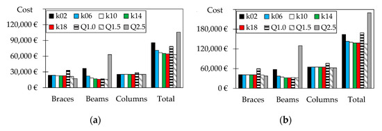
Figure 2.
Structural costs of members of the braced frames: (a) 4-storey structures; (b) 8-storey structures.
Regarding the structures designed according to the proposed criterion, the figure shows that the smaller the value of k, the greater the structural costs of the braced beams. However, for values of k larger than 1.0, the reduction in structural costs is low. Since the elastic lateral stiffness of the braced frame (and consequently the period of vibration) is only marginally affected by the flexural stiffness of the beams, the adopted value of k has a negligible impact on the costs of the braces and columns, regardless of the considered number of stories. Structures designed according to the conventional approach are the most expensive. Indeed, despite the lower cost of the braces due to the adoption of a higher value of the behaviour factor (q = 2.5), a significant increase in the structural costs of the beams is produced by the application of capacity design principles. Structural costs required for case Q1.0 are smaller than those required for case Q2.5 despite an increase in the structural costs of the braces related to the higher seismic internal forces on these members. Case Q1.5 is the least expensive and is characterised by structural costs slightly lower (2%) than those of case k18.
5. Numerical Analyses
Nonlinear incremental dynamic analyses were performed using the OpenSees [29] computer program. The method of numerical integration used to solve the equations of motion was that proposed by Newmark. The values of gamma and beta were set equal to 0.50 and 0.25, which lead to the average acceleration method. To accelerate convergence, the Krylov–Newton algorithm object, which uses a Krylov subspace accelerator, was used [30].
5.1. Seismic Input and Numerical Model
The seismic input consists of a set of ten accelerograms artificially generated by the SIMQKE computer program. Each accelerogram was generated so that its response spectrum matches the elastic spectrum given in EC8 for soil A, with an equivalent viscous damping ratio equal to 5%. Each ground motion had total duration of 30.5 s and was enveloped by a three-branch compound function. The duration of the stationary part was set equal to 7 s. More details about the accelerograms are given in [31]. The value of ag of the ground motions was increased in steps of 0.025 g.
The numerical model developed for each structure includes one braced frame and the gravity columns of half of the structure. The braces were modelled by means of four nonlinear force-based beam-column elements, according to the proposal of Uriz et al. [32]. The inelastic response of each element was monitored at three integration points. To simulate the effects of imperfections, the initial camber was set equal to 0.1% times the length of the brace and large displacements were accounted for through corotational theory. The braced beams were simulated by two beams with hinge elements. The position and weights of the integration points were defined according to the modified Gauss–Radau plastic hinge integration method [33]. The length of the plastic hinge was set equal to the depth of the beam cross-section. The brace cross-section and that of the beams within the plastic hinge was discretized into fibres. Out of the uniaxial material models available in the Opensees library, to replicate the stress–strain curve of the steel members, the one proposed by Giuffrè–Menegotto–Pinto (named as Steel02 in Opensees) was selected. Columns of the braced frame were considered as fragile members and consequently were modelled as elastic members.
The Rayleigh formulation was used to introduce damping. According to this formulation, the damping matrix was obtained as a linear combination of the mass matrix and the stiffness matrix updated at the current step of the analysis. The coefficients of this linear combination were defined so that an equivalent viscous damping ratio equal to 0.03 was assigned to the first and the third modes of vibration of the system. The P-Δ effects were included in the numerical analyses.
5.2. Response Parameters
To evaluate the fulfilment of the SD and NC limit states, the response of the dissipative members (braces and braced beams) was expressed in terms of ductility demand-to-capacity ratios. To this end, the damage index DI of the braces is defined in [19] as follows:
where μd and μf are the ductility demand and capacity of the relevant brace, respectively. Specifically, the ductility demand was calculated as the ratio of the sum of the absolute values of maximum elongation and shortening of the brace over the elongation corresponding to yielding of the brace. In keeping with [19], with regard to the Near Collapse (NC) limit state, a limit value of the DI equal to 1.0 was considered, whereas a limit value of DI equal to 0.75 was considered to be representative of the achievement of the Significant Damage (SD) limit state.
The damage index of the beams was calculated as the ratio of the demanded plastic rotation to the plastic rotation capacity, defined as reported in Eurocode 8 part 3 [34]. Specifically, at the achievement of the NC limit state, for axial load ratios not higher than 0.3, the rotation capacity was equal to 8 and 3 times the chord rotation at yield (θy) for Class 1 and Class 2 cross-sections, respectively. At the achievement of the SD limit state, instead, the rotation capacity was equal to 6 θy and 2 θy for the Class 1 and Class 2 cross-sections, respectively.
Regarding the fragile members (beams and columns), the verifications of yielding or instability were conducted in terms of the resistance index RI, stability index SI and lateral torsional buckling index TI. These indexes were calculated following the prescriptions provided by EC3 [25] for the verification of members subjected to combined axial force and bending moment:
where Nb,Rd,y and Nb,Rd,z are the buckling resistance about the strong and weak axes; MRd,y and MRd,z are the design resistances against bending about the two abovementioned axes; , , and are the interaction factors evaluated according to method 2 in Annex B of EC3 [25]; and χLT is the reduction factor due to lateral torsional buckling. In the abovementioned equations, the values of resistances were determined considering the partial safety factors γM0 and γM1 equalling 1.
Finally, residual drifts were determined according to the procedure reported in [35].
6. Validation of the Proposed Method
6.1. Methodology
The seismic response of the designed case studies was assessed, with reference to the attainment of both the SD and NC limit states, by means of fragility curves. To this end, the ag corresponding to the achievement of the relevant limit state was determined by incremental nonlinear dynamic analysis (IDA). The IDA was run scaling the set of 10 accelerograms (already presented in Section 5.1) for increasing values of ag. For each of the considered accelerograms, the value of the peak ground acceleration ag,LS corresponding to the relevant limit state (LS) was determined according to two criteria: (i) the minimum peak ground acceleration, leading to the achievement of the deformation capacity of the dissipative members (i.e., DI = 1 at the NC limit state or DI = 0.75 at the SD limit state for braces, and the plastic rotation is equal to the relevant plastic rotation capacity in ductile beams); (ii) the minimum value of ag between those corresponding to the attainment of the deformation capacity in the dissipative members and that corresponding to yielding (i.e., RI = 1) or to buckling (i.e., SI = 1 or TI = 1) of fragile members.
The ten values of ag,LS corresponding to each limit state were used to build the fragility function; i.e., the probability of exceedance of the limit state at different intensity measures (IM). A lognormal cumulative distribution function is considered here:
where x is the assigned value of IM (i.e., of ag) and θ and σ are the mean and standard deviation of the logarithms of the peak ground accelerations corresponding to the achievement of the considered limit state, respectively. As reported in [36], θ and σ are calculated as
where n is the number of accelerograms.
Fragility curves were finally used to evaluate the probability of exceedance of the considered limit state for a peak ground acceleration equal to the target value; i.e., 0.15 g at the SD limit state and 0.189 g at the NC limit state. This latter value was determined by the following equation given in Eurocode 8 [16], assuming that the NC limit state should be fulfilled for seismic events with a probability of exceedance PVR equal to 5% in 50 years:
As an example, Figure 3 shows the fragility curves obtained for the 4-storey cases Q1.0 and Q2.5 at the SD limit state. The red curve is obtained starting from the ag,SD values corresponding to the achievement of the deformation capacity of the dissipative members (first option discussed in this Section), whereas the black curve is obtained based on the ag,SD values considering both ductile and fragile members (second option discussed in this Section). With regard to system Q1.0 (Figure 3a), if only ductile members were considered, the probability of exceedance of the SD limit state for ag = 0.15 g (see the red arrow) would be equal to 8.1%, whereas it increases to 18.8% (see the black arrow) because of the earlier fragile collapse of some members. Instead, regarding system Q2.5, the analysis of Figure 3b shows that case Q2.5 is considerably oversized and the probability of exceedance of the SD limit state for ag = 0.15 g is equal to 0% if only ductile members were considered. This is due to the restrictive conditions introduced (1) on the size of the brace of the upper floor due to the normalized slenderness that has to be lower than 2.0; and (2) on the size of the braces of the other storeys because of the limits imposed to the maximum scattering in the distribution of the overstrength . However, the probability of exceedance of the SD limit state increases to 67.3% because of the fragile collapse of some members and thus the response of this case study is deemed not adequate because the abovementioned probability of exceedance is higher than 50%.
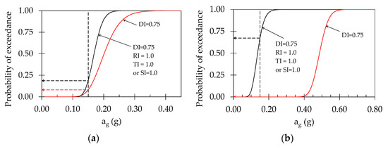
Figure 3.
Fragility curves at the SD limit state of a 4-storey case study: (a) Q = 1.0; (b) Q = 2.5.
6.2. Response at the SD Limit State
The probabilities of exceedance of the SD limit state (i.e., for ag = 0.15 g) obtained for all the considered case studies are represented by the histograms of Figure 4. In particular, Figure 4a,b refer to the 4-storey and 8-storey structures, respectively. Plots in the first line show the results related to ductile members only, while those in the second line show the results obtained considering both the verifications of ductile and fragile members.
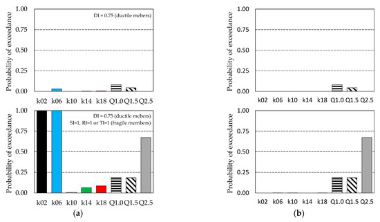
Figure 4.
Probability of exceedance of the SD limit state for ag = 0.15 g: (a) 4-storey structures; (b) 8-storey structures.
As a general trend, the probabilities of exceedance of the SD limit state of the considered systems determined considering only ductile members are always lower than 10%. Thus, all the cases provide a satisfactory response. If the probability of exceedance of the SD limit state is evaluated considering the requirements of both ductile and fragile elements, cases k02 and k06 provide a probability of exceedance larger than 50% in the case of 4-storey structures, whereas case Q2.5 provides no suitable performance independently of the number of storeys of the buildings.
To investigate on this result, Figure 5 shows, for each designed structure, the percentage of cases in which the SD limit state is attained because of the achievement of the capacity in a brace, a column or a beam. For a fixed case study, when the majority of collapses are caused by failure of columns or failure of fragile beams, it means that the considered structure has a poor dissipative capacity and is characterized by a fragile seismic response. On the contrary, a ductile seismic response is provided by those structures that tend to collapse mainly due to the failure of the braces.
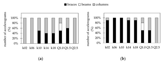
Figure 5.
Percentage number of accelerograms leading to DI = 0.75 in braces or RI = 1, SI = 1, TI = 1 in beams and columns: (a) 4-storey structures; (b) 8-storey structures.
The figure shows that in case Q2.5, the SD limit state is always achieved because of the fragile collapse of columns. In the case of 4-storey structures, this also occurs for cases k02 and k06, whereas in the cases k10 to k18 the column failure occurs for about 50% of the accelerograms. It is interesting to remark that the column cross-sections used for the 4-storey frames are the same as in the case studies k02 to k18 and that the column at the base has a minimum overstrength. Thus, if the column cross-sections are not oversized, a braced beam with moderate flexural stiffness and strength partially prevents column failure.
The performance of the designed case study has also been evaluated in terms of the residual interstorey drifts. The limit value corresponding to the attainment of the SD limit state was equal to 0.5% h, h being the interstorey height, in accordance with the provision given by FEMA [37]. Values of residual interstorey drifts lower than 0.5% h are deemed acceptable and the structure is worthy to be repaired. As the interstorey height of the building is equal to 4.0 m, the limit value of the residual interstorey drift is equal to . The probabilities of exceedance of the maximum value of the residual interstorey drifts for a peak ground acceleration equal to 0.15 g are very low for all the considered structures and thus are not reported in any figure.
6.3. Response at the NC Limit State
Regarding the NC limit state, Figure 6 presents the probabilities of exceedance, whereas Figure 7 shows the percentage of cases in which the limit state is attained because of the collapse of a brace, column or beam. The figure confirms the trends highlighted for the SD limit state for 4-storey structures.
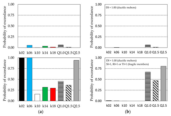
Figure 6.
Probability of exceedance of the NC limit state for ag = 0.189 g: (a) 4-storey structures; (b) 8-storey structures.
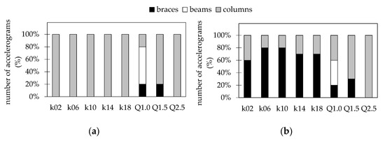
Figure 7.
Percentage number of accelerograms leading to DI = 1.00 in braces or RI = 1, SI = 1, TI = 1 in beams and columns: (a) 4-storey structures; (b) 8-storey structures.
In the case of 8-storey structures, the structures designed according to the proposed approach provide a low probability of exceedance independently of the considered value of k, whereas cases Q1.0, Q1.5 and Q2.5 provide a probability of exceedance close or larger than 50%.
7. Conclusions
This paper proposes a design approach for chevron-braced frames in low seismicity areas. The procedure allows yielding of the braced beams but requires a minimum flexural stiffness of this member to avoid large inelastic deformation demands for the brace in compression. Further, the procedure does not require the application of capacity design rules.
Structures with a 4-storey or 8-storey standing on stiff soil were designed according to the proposed procedure and also following the procedures stipulated in Eurocode 8 for dissipative or non-dissipative braces. This latter procedure was applied twice, assuming a behaviour factor equal to either 1.0 or 1.5. The application of the design procedures led to the following conclusions:
- -
- The structures designed according to the proposed procedure are characterized by structural costs about 35% smaller than those of structures designed according to the European seismic code for dissipative braces.
- -
- The structures designed according to the proposed procedure are characterized by structural costs similar to those obtained in the case of structures designed assuming non-dissipative braces and a behaviour factor equal to 1.5, and smaller (about 15%) than those obtained assuming a behaviour factor equal to 1.0.
The response of the designed structures was determined by incremental nonlinear dynamic analysis, and the probability of exceedance of Significant Damage and Near Collapse limit states for seismic events, with a probability of exceedance equal to 10% and 5% in 50 years, was determined and compared. The assessment of the seismic performance led to the following conclusions:
- -
- The structures designed according to the procedure stipulated in the European seismic code for dissipative braces give a probability of exceedance of the considered limit states larger than 50%.
- -
- The structures designed according to the procedure stipulated in the European seismic code for non-dissipative braces give a probability of exceedance of the Significant Damage limit state smaller than 50%, independently of the building height. The same structures give a satisfactory response at the Near Collapse limit state only for low-rise buildings.
- -
- The structures designed according to the proposed approach provide a satisfactory response for all the considered cases.
The authors underline that the abovementioned conclusions were drawn for structures standing on stiff soil and in low-seismicity areas. Indeed, all the structures were designed to sustain a peak ground acceleration equal to 0.15 g. More analyses are required to generalize the obtained results.
Author Contributions
Conceptualization, methodology, software, formal analysis, writing—review and editing: F.B., M.B., M.C., E.M.M. and P.P.R. All authors have read and agreed to the published version of the manuscript.
Funding
This study was partially supported by the program of University of Catania within the research project “Piano di incentivi per la ricerca di Ateneo 2020/2022 (Pia.ce.ri.)—Starting Grant” of the Department of Civil Engineering and Architecture.
Institutional Review Board Statement
Not applicable.
Informed Consent Statement
Not applicable.
Data Availability Statement
Publicly available datasets were analysed in this study. This data can be found here: http://www.dica.unict.it/users/mbosco/VCBF-AlternativeApproach.htm.
Conflicts of Interest
The authors declare no conflict of interest.
References
- Goggins, J.M.; Broderick, B.M.; Elghazouli, A.Y.; Lucas, A.S. Behaviour of tubular steel members under cyclic axial loading. J. Constr. Steel Res. 2006, 62, 121–131. [Google Scholar] [CrossRef] [Green Version]
- Tremblay, R. Inelastic seismic response of steel bracing members. J. Constr. Steel Res. 2002, 58, 665–701. [Google Scholar] [CrossRef]
- Han, S.W.; Kim, W.T.; Foutch, D.A. Seismic behavior of HSS bracing members according to width e thickness ratio under symmetric cyclic loading. J. Struct. Eng. 2007, 133, 264–273. [Google Scholar] [CrossRef]
- Fell, B.V.; Kanvinde, A.M.; Deierlein, G.G.; Myers, A.T. Experimental investigation of inelastic cyclic buckling and fracture of steel braces. J. Struct. Eng. 2009, 135, 19–32. [Google Scholar] [CrossRef]
- Faytarouni, M.; Shen, J.; Seker, O.; Akbas, B. Evaluation of brace fracture models in seismic analysis of concentrically braced frames. J. Constr. Steel Res. 2019, 162, 105709. [Google Scholar] [CrossRef]
- Tang, X.; Goel, S.C. Brace fractures and analysis of phase I structures. J. Struct. Eng. 1989, 115, 1960–1976. [Google Scholar] [CrossRef]
- Lee, S.; Goel, S.C. Seismic Behavior of Hollow and Concrete-Filled Square Tubular Bracing Members; Research Report UMCE 87–11; Department of Civil Engineering, University of Michigan: Ann Arbor, MI, USA, 1987. [Google Scholar]
- Tremblay, R.; Archambault, M.H.; Filiatrault, A. Seismic response of concentrically braced steel frames made with rectangular hollow bracing members. J. Struct. Eng. 2003, 129, 1626–1636. [Google Scholar] [CrossRef]
- Tirca, L.; Chen, L. Numerical simulation of inelastic cyclic response of HSS braces upon fracture. Adv. Steel Constr. 2014, 10, 442–462. [Google Scholar]
- Karamanci, E.; Lignos, D.G. Computational approach for collapse assessment of concentrically braced frames in seismic regions. J. Struct. Eng. 2014, 140, A4014019. [Google Scholar] [CrossRef]
- Costanzo, S.; D’Aniello, M.; Landolfo, R. Seismic design criteria for Chevron CBFs: European vs. North American codes (Part-1). J. Constr. Steel Res. 2017, 135, 83–96. [Google Scholar] [CrossRef]
- Wang, Y.D.; Nastri, E.; Tirca, L.; Montuori, R.; Piluso, V. Comparative Response of Earthquake Resistant CBF Buildings Designed According to Canadian and European Code Provisions. Key Eng. Mater. 2018, 763, 1155–1163. [Google Scholar]
- Costanzo, S.; D’Aniello, M.; Landolfo, R. Critical review of seismic design criteria for chevron concentrically braced frames: The role of the brace-intercepted beam. Ing. Sismica 2015, 1, 72–89. [Google Scholar]
- D’Aniello, M.; Costanzo, S.; Landolfo, R. The influence of beam stiffness on seismic response of chevron concentric bracings. J. Constr. Steel Res. 2015, 112, 305–324. [Google Scholar] [CrossRef]
- Longo, A.; Montuori, R.; Piluso, V. Seismic reliability of V-braced frames: Influence of design methodologies. Earthq. Eng. Struct. Dyn. 2009, 38, 1587–1608. [Google Scholar] [CrossRef]
- CEN. EuroCode 8: Design of Structures for Earthquake Resistance—Part 1: General Rules, Seismic Actions and Rules for Buildings; EN 1998-1; European Committee for Standardization: Bruxelles, Belgium, 2004. [Google Scholar]
- Marino, E.M.; Nakashima, M. Seismic performance and new design procedure for chevron-braced frames. Earthq. Eng. Struct. Dyn. 2005, 35, 433–452. [Google Scholar] [CrossRef]
- Costanzo, S.; D’Aniello, M.; Landolfo, R. Seismic design criteria for chevron CBFs: Proposal for the next EC8 (part-2). J. Constr. Steel Res. 2017, 138, 17–37. [Google Scholar] [CrossRef]
- Barbagallo, F.; Bosco, M.; Marino, E.M.; Rossi, P.P. Proposal and validation of a design procedure for concentrically braced frames in the chevron configuration. Earthq. Eng. Struct. Dyn. 2021, 50, 3041–3063. [Google Scholar] [CrossRef]
- Longo, A.; Montuori, R.; Piluso, V. Plastic design of seismic resistant V-Braced frames. J. Earthq. Eng. 2008, 12, 1246–1266. [Google Scholar] [CrossRef]
- Barbagallo, F.; Bosco, M.; Marino, E.M.; Rossi, P.P. Seismic performance and cost comparative analysis of steel braced frames designed in the framework of EC8. Eng. Struct. 2021, 240, 112379. [Google Scholar] [CrossRef]
- Marino, E.M. A unified approach for the design of high ductility steel frames with concentric braces in the framework of Eurocode 8. Earthq. Eng. Struct. Dyn. 2014, 43, 97–118. [Google Scholar] [CrossRef]
- Roeder, C.W.; Sen, A.D.; Asada, H.; Ibarra, S.M.; Lehman, D.E.; Berman, J.W.; Tsai, K.-C.; Tsai, C.-Y.; Wu, A.-C.; Wang, K.-J.; et al. Inelastic behavior and seismic design of multistory chevron-braced frames with yielding beams. J. Constr. Steel Res. 2020, 167, 105817. [Google Scholar] [CrossRef]
- Tan, Q.; Lehman, D.E.; Roeder, C.W.; Berman, J.W.; Sen, A.D.; Wu, B. Design-parameter study on seismic performance of chevron-configured SCBFs with yielding beams. J. Constr. Steel Res. 2021, 179, 106561. [Google Scholar] [CrossRef]
- CEN. EuroCode 3: Design of Steel Structures—Part 1-1: General Rules and Rules for Buildings; EN 1993-1-1; European Committee for Standardization: Bruxelles, Belgium, 2005. [Google Scholar]
- Istituto Nazionale Di Geofisica E Vulcanologia. Available online: www.ingv.it (accessed on 31 October 2021).
- CEN. Eurocode 1: Actions on Structures—Part 1-1: General Actions—Densities, Self-Weight, Imposed Loads for Buildings; EN 1991-1; European Committee for Standardization: Bruxelles, Belgium, 2005. [Google Scholar]
- Decreto 27 Febbraio 2013. Nuovo Prezzario Unico Regionale per i Lavori Pubblici. Supplemento Ordinario n. 2 alla Gazzetta Ufficiale della Regione Siciliana (p. I) n. 13 del 15-3-2013 (n. 9). Available online: http://www.gurs.regione.sicilia.it/Gazzette/g13-13o2/g13-13o2.pdf (accessed on 31 October 2021).
- Mazzoni, S.; McKenna, F.; Scott, M.H.; Fenves, G.L.; Jeremic, B. OpenSees Command Language Manual, Pacific Earthquake Engineering Research Center; University of California: Berkeley, CA, USA, 2007; Available online: https://opensees.berkeley.edu/wiki/index.php/Main_Page (accessed on 31 October 2021).
- Scott, M.H.; Fenves, G.L. A Krylov Subspace Accelerated Newton Algorithm: Application to Dynamic Progressive Collapse Simulation of Frames. J. Struct. Eng. 2010, 136, 473–480. [Google Scholar] [CrossRef]
- Amara, F.; Bosco, M.; Marino, E.M.; Rossi, P.P. An accurate strength amplification factor for the design of SDOF system with P-Δ effects. Earthq. Eng. Struct. Dyn. 2014, 43, 589–611. [Google Scholar] [CrossRef]
- Uriz, P.; Filippou, F.C.; Mahin, S.A. Model for cyclic inelastic buckling of steel braces. J. Struct. Eng. 2008, 134, 619–628. [Google Scholar] [CrossRef]
- Scott, M.H.; Fenves, G.L. Plastic hinge integration methods for force-based beam-column elements. J. Struct. Eng. 2006, 132, 244–252. [Google Scholar] [CrossRef]
- CEN. EuroCode 8: Design of Structures for Earthquake Resistance. Part 3: Assessment and Retrofitting of Buildings; EN 1998-3; European Committee for Standardization: Bruxelles, Belgium, 2005. [Google Scholar]
- Bosco, M.; Marino, E.M.; Rossi, P.P. Design of steel frames equipped with BRBs in the framework of Eurocode 8. J. Constr. Steel Res. 2015, 113, 43–57. [Google Scholar] [CrossRef]
- Backer, J.W. Efficient analytical fragility functions fitting using dynamic structural analysis. Earthq. Spectra 2015, 31, 579–599. [Google Scholar] [CrossRef]
- FEMA 356. Prestandard and Commentary for the Seismic Rehabilitation of Buildings; Federal Emergency Management Agency: Washington, DC, USA, 2000.
Publisher’s Note: MDPI stays neutral with regard to jurisdictional claims in published maps and institutional affiliations. |
© 2021 by the authors. Licensee MDPI, Basel, Switzerland. This article is an open access article distributed under the terms and conditions of the Creative Commons Attribution (CC BY) license (https://creativecommons.org/licenses/by/4.0/).