Article

Novel Beam Scan Method of Fabry–Perot Cavity (FPC) Antennas

1
Department of Electrical Engineering, Sejong University, 209 Neungdong-ro, Gwangjin-gu, Seoul 05006, Korea
2
The Specific Radar Team, Hanwha Systems, 491-23, Gyeonggidong-ro, Namsa-myeon, Cheoin-gu, Yongin-si 17121, Gyeonggi-do, Korea
*
Author to whom correspondence should be addressed.
Appl. Sci. 2021, 11(22), 11005; https://doi.org/10.3390/app112211005
Submission received: 13 October 2021 / Revised: 16 November 2021 / Accepted: 17 November 2021 / Published: 20 November 2021

Abstract

:

Featured Application

A new beam scanning method of FPC antennas is proposed, validated by fabrication and measurements.

Abstract

A new beam scanning method of a Fabry–Perot cavity (FPC) antenna is proposed. To obtain high gain in a target direction with a reduced sidelobe level (SLL), we devised a tapered partially reflective surface (PRS) as a superstrate. Moreover, to attain various beam scanning directions, a phase-controllable artificial magnetic conductor (AMC) ground plane with a broad reflection phase range and high reflection magnitudes was introduced. In the proposed method, a new formula to satisfy an FP resonance condition in a cavity for a scanned beam is also suggested. According to the formula, the FPC antenna can precisely scan the main beam in designed target directions with well-maintained high gain, which has been hardly achievable. In addition, our method demonstrates the potential of electrical beam-scanning antennas by employing active RF chips on the AMC cells. To validate the method, we fabricated a prototype FPC antenna for a scanned beam at θ = 30°. Furthermore, we conducted an additional simulation for a different beam scanning angle as well. Good agreement between the expected and experimental results verifies our design approach.

1. Introduction

In state-of-the-art communication technologies, high gain antennas with a beam-scanning ability have been receiving considerable interest to secure a longer and broader communication area. Among various high gain antennas, phased-array [1,2] and reflect-array [3,4,5] antennas are especially renowned due to their beam-forming abilities. In [2,3], for instance, discrete beam-steering and continuous beam-scanning capabilities are realized, respectively. However, the phased-array antennas demand not only complex feeding networks but also phase shifters because of the many radiating elements, which causes high complexity and high expense. On the other hand, the reflect-array antennas do not require complex feeding networks as they usually employ only a single excitation source. Moreover, considering electrical beam-scanning [5], the reflect-array antenna is more favorable than the phased-array antenna because a bias network controlling each active element in the reflect-array is much simpler than the phase shifting of the phased-array antenna. However, the reflect-array antenna requires quite a long feeding distance between a reflect-array and a feeding antenna to guarantee high illumination and accurate reflection behaviors of each cell [3,4,5], making the antenna too bulky for commercial applications.
Meanwhile, a Fabry–Perot cavity (FPC) antenna, consisting of a partially reflective surface (PRS) and a single excitation source, has also been actively studied as it can provide high gain despite its simple configuration [6]. In [7,8], for example, a combination of the PRS and a phase correcting structure is introduced to enhance. In [9], an FPC antenna using an all-dielectric PRS and PEC walls is studied to realize low profile as well as high gain. Furthermore, in [10], a PRS based on low-cost 3D printing technology is employed to obtain not only high gain, but also polarization reconfigurability.
However, they have the shortcoming that the antenna cannot achieve a scanned beam. To overcome this issue, some groups have introduced a phase-controllable PRS and obtained beam-steering capability in the FPC antenna. For example, a 3D printed stepped dielectric [11], a fluidically programmable metasurface [12], and an electrical beam-switching metasurface [13,14,15] have been suggested as a PRS. Nevertheless, they have several crucial problems such as a low beam-switching speed [11,12], fluctuating radiation performances depending on the scanning angle [12], and a narrow steering range [13,14,15].
As a solution to these problems, we propose a new beam-scan method of an FPC antenna. The proposed method introduces an artificial magnetic conductor (AMC) ground plane that is based on a newly introduced design formula instead of an optimization used in [16]. Moreover, a tapered PRS is devised to suppress a sidelobe level (SLL), which is practical for a finite antenna size [17]. Compared with the prior works, the strong points of our method are as follows:
  • A predictable beam-scan direction based on a newly introduced design formula;
  • A wide beam-scan range with a well-maintained high gain;
  • A continuously changeable beam-scan direction.
To validate our idea, we fabricated and measured a prototype FPC antenna for a scanned beam at θ = 30°. Moreover, we performed an additional simulation of a normal radiation (θ = 0°) case as well. Consequently, by comparing simulation and measurement results, we have successfully proven the validity of our design proposal.
All simulations have been conducted using CST Microwave Studio [18].

2. Materials and Methods

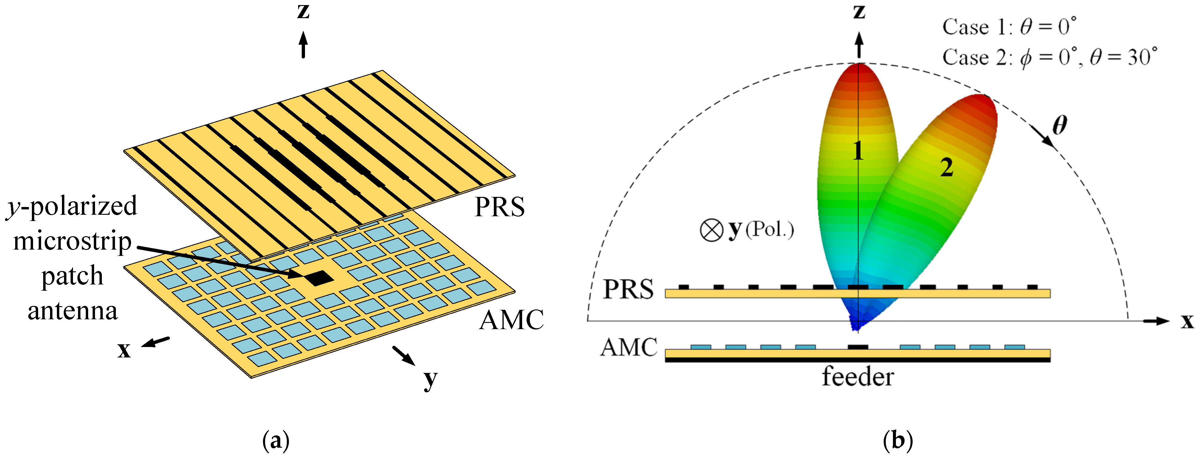
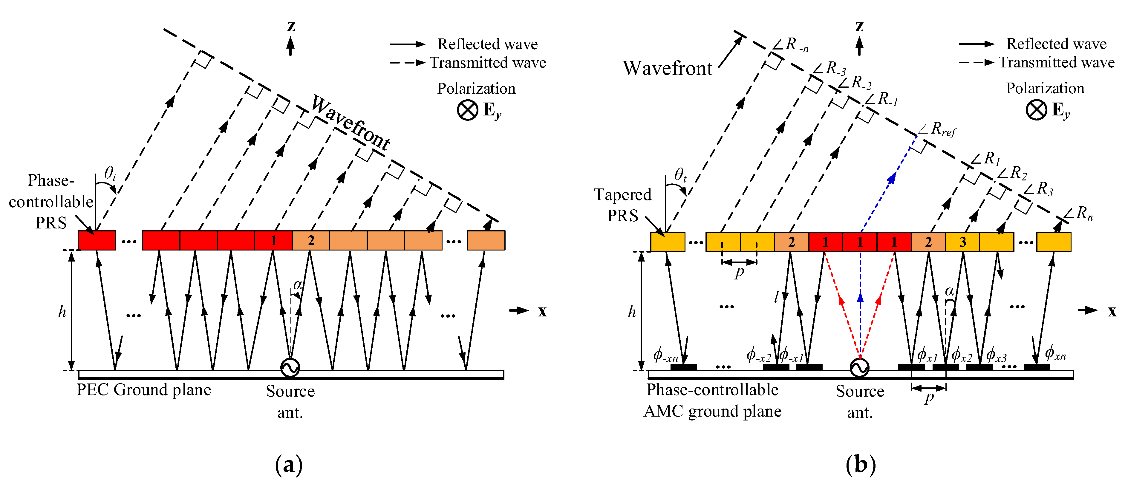
2.1. Operation Principle of the Proposed Antenna

Overviews of the FPC antenna based on the proposed design method and its beam-scanning scheme are presented in Figure 1. The proposed antenna consists of a tapered PRS superstrate and an AMC ground plane, forming an FP cavity. By satisfying an FP resonance condition in the cavity and adequately adjusting the reflection phase of each AMC cell, the antenna can successfully produce a scanned beam with fairly high gain in the desired target direction of θ = 30° on the xz-plane (ϕ = 0°). For a feeding antenna, a y-polarized microstrip patch antenna is employed instead of a slot antenna or others for easy fabrication [19].
Figure 2 describes the conventional and the proposed operation principles of an FPC antenna for a scanned beam. For the FPC antenna, there are two kinds of fields distinguished by the PRS; one is being transmitted through, the other is being reflected. By carefully utilizing the reflected fields to generate an FP resonance in the cavity, the antenna can obtain high gain in a target direction [6].
Now we are going to discuss how to scan a main beam in the FPC antenna. To obtain the scanned beam in the target direction, all fields transmitted through the PRS should be in-phase on the tilted target wavefront. For that, we can consider the following two methods:
  • A phase-controllable PRS superstrate (see Figure 2a);
  • A phase-controllable AMC ground plane (see Figure 2b).
First, let us consider method 1 which is used in previous works. In [11,12,13,14,15], a phase-controllable PRS is devised to make transmitted fields constructively interfere on the inclined target wavefront. However, there is a critical problem that a beam-scan direction is unpredictable as there is no precise design formula. Moreover, method 1 is not suitable for commercial applications, requiring wide beam-scan capability due to the limitations of a PRS: the narrow reflection and transmission phase ranges. In fact, in method 1, the PRS should have wide reflection and transmission phase ranges with a high reflection magnitude to provide various beam scan-directions as well as high gain [6]. However, in general, it is extremely difficult for an ordinary PRS to realize broad phase ranges while maintaining high reflection magnitudes [12,13,14,15]. Though we can use a stacked PRS consisting of two or three layers for the wide ranges, it is obviously unfavorable in obtaining high gain (or high efficiency) due to high material losses [20].
To overcome these problems, we propose method 2 which introduces a phase-controllable AMC ground plane. The phase-controllable AMC is far more desirable than the phase-controllable PRS for various beam-scan directions because the AMC generally provides a much wider reflection phase range with very low loss compared with the PRS [21]. Moreover, another strong point of the AMC is its biasing configuration for electrical beam-scanning. To understand this, we need to revisit the configuration of electrical beam-scanning antennas. As we know well, they employ active RF chips such as varactor- or PIN-diodes that require DC bias lines. Varactor-diodes, for example, are usually selected for continuous beam-scanning as their electrical properties are continuously varied according to the applied reverse DC voltage. When installing the varactor-diodes on the PRS, bias lines will be in the cavity, as described in Figure 3a. In this case, the fatal problem is that the FP resonance becomes extremely difficult to be considered as the bias lines significantly affect the fields in the cavity, which ultimately harms the antenna’s radiation. Even if PIN-diodes were applied for a discrete beam-steering, bias lines would still be located in the radiation area, which would also adversely affect the antenna performance.
However, when using the active AMC instead of the active PRS, all bias lines can be placed beneath the ground plane (see Figure 3b), which hardly affects the radiation performance. Therefore, in these regards, we can conclude that the AMC ground plane is far more favorable than the PRS in respect to numerous future phase-control applications.
So far, we have described the reason why the AMC ground plane is introduced. From now on, we are going to explain how to define a proper reflection phase of each AMC cell to obtain a desired scanned beam. For a scanned beam, each phase of fields transmitted through the PRS should be equal on the tilted target wavefront. These phases, ∠R−n to ∠Rn in Figure 2b, can be derived as
R ± n = β ( p 2 + h 2 + 2 n l ) + i = 1 n ( Γ i + ϕ ± x i ) + Τ n + 1   ( n     1 )  
where β is the propagation constant in free space, h is the height of the PRS, p is the period of each PRS and AMC cell, l is the length of a ray path between the AMC and PRS, ϕ±xn is the reflection phase of each ±nth AMC cell, and ∠Γn and ∠Τn are the reflection and transmission phases of the ±nth PRS cell, respectively. The cell number n is represented in Figure 2.
Equation (1) means that we can control all the transmitting rays’ phases by adequately changing each AMC cell’s reflection phase. However, there are three phase-uncontrollable rays directly passing through the PRS without any reflection by the AMC, which are depicted as red short-dashed lines in Figure 2b. Among the phase-uncontrollable rays, the blue-dashed one (see Figure 2b) must be the most influential on beam-scanning as they are normally bouncing between the PRS and the ground plane, which yields the strongest radiation power. Therefore, we set the strongest ray’s phase as the reference ∠Rref when designing a target wavefront, which is obtainable through a simulation where there is a superstrate of three PRS cells that the phase-uncontrollable fields pass through. According to the simulation, ∠Rref is about −130° above 1 mm from the center of the PRS at the design frequency. Now, the relationship among the phases ∠R±n on the inclined target wavefront (see Figure 2b) can be derived with regard to ∠Rref as follows:
R ± n = R r e f β ( n + 1 ) p sin θ t           ( n 1 )
Finally, by combining the Equations (1) and (2), the required reflection phase of each AMC cell can be derived as
ϕ ± x 1   or   ± y 1 = β ( p 2 + h 2 + 2 l 2 p sin θ t ) Γ 1 P o l . Τ 2 P o l . + R r e f           ( n = 1 )
ϕ ± x n   or   ± y n = β ( 2 l p sin θ t ) Γ n P o l . + Τ n P o l . Τ n + 1 P o l .           ( n 2 )
where ϕ±xn and ϕ±yn are the reflection phases of the ±nth AMC cell along the x- and y-axis, respectively, and the superscript Pol. means the polarization mode of fields incident on the PRS. Since both the reflection and transmission coefficients of the PRS are highly dependent on the incident angle and polarization [20], it is very important to consider the incident conditions when determining the coefficients, which will be further elucidated in Section 2.3.
In the previous paragraphs, we described how the phase-uncontrollable rays passing directly through the PRS are considered for building a target wavefront; the phase of the most influential rays (blue-dotted line in Figure 2b) is selected as the reference. However, another phase of two rays (red dashed lines in Figure 2b) is still out of control, which may adversely affect beam-scanning. Thus, their transmission through the PRS should be suppressed, which is achievable by increasing the reflection magnitude of the PRS cells. On the other hand, at the same time, high reflection magnitudes of the PRS make impedance matching difficult for an FPC antenna. Therefore, the reflection magnitudes of the PRS cells, where the phase-uncontrollable rays pass through, should be determined based on a trade-off relationship between the beam-scan ability and the good impedance matching property. In this work, when the corresponding reflection magnitude is 0.86, the proposed antenna provides a well-scanned beam in the target direction with acceptable impedance matching performance.

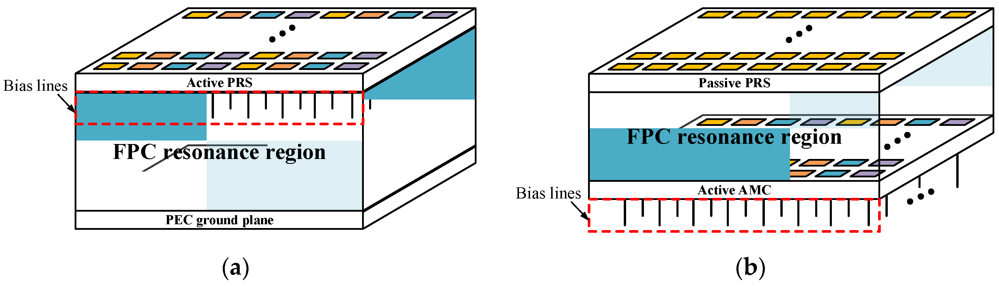
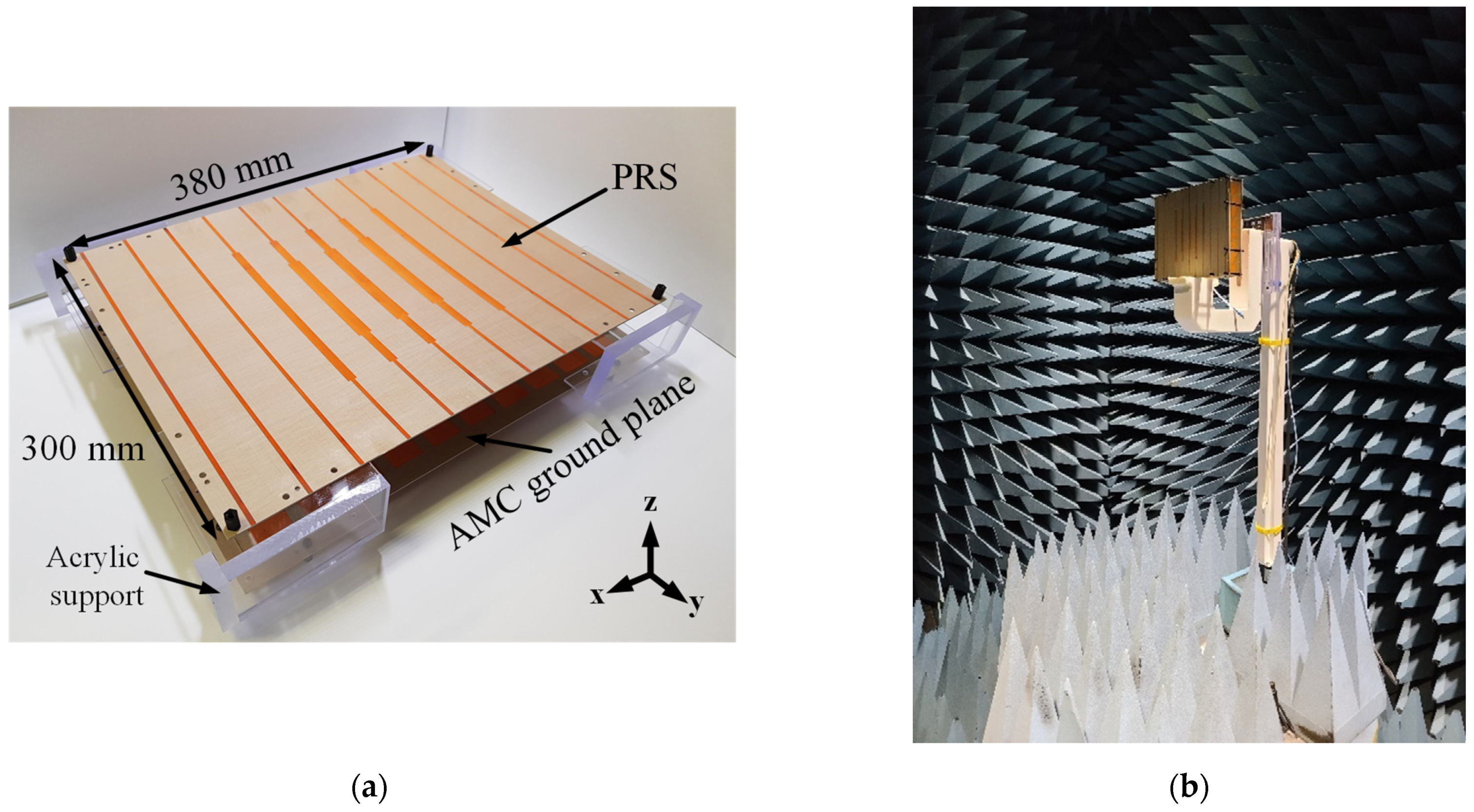
2.2. Deployment of a PRS Superstrate and an AMC Ground Plane

Figure 4 shows the deployment of the proposed PRS superstrate and the AMC ground plane. As we can see in Figure 4a, the strip lines of the PRS are symmetric to the y-axis, which is intended for a symmetrical beam-scan performance on the H-plane (xz-plane). Moreover, they are tapered toward the edges so as to suppress an SLL [17]. By tapering the widths of the strip lines, their reflection magnitudes are lowered to the edges. Thus, while fields in the cavity propagate to lateral openings experiencing multiple reflections between the PRS and the AMC, most of them should be transmitted through the PRS before leaking out of the openings. Consequently, the SLL gets decreased thanks to the reduced leaky components contributing to the undesirable sidelobe. In our work, the proposed PRS has three tapering reflection magnitudes of 0.86, 0.72, and 0.50 toward the edges.
Now, we move on to the AMC ground plane in Figure 4b, which is employed for the aforementioned phase control. The AMC ground plane consists of 76 unit cells arranged with a period p of 35 mm. Each AMC cell has the required reflection phase calculated by (3) and (4) at the design frequency, and their corresponding lengths are listed in Table 1. In Figure 4b, the same-colored cells have the same reflection coefficients, and there are eleven different colors in total. In addition, since the proposed antenna is designed for a scanned beam along the x-axis, the phase distribution of the cells is symmetric with respect to the x-axis. In Figure 4, the regions enclosed by the red and the blue lines are related to polarization modes incident on the cells, which will be explained in the following subsection in more detail.
Figure 5 shows the geometry of the source feeder that is a y-polarized U-slot microstrip patch antenna, whose feeding point is fp far from the center. The U-slot is introduced to improve impedance matching of our antenna, which is difficult due to the strong influence of reflected fields in the cavity.

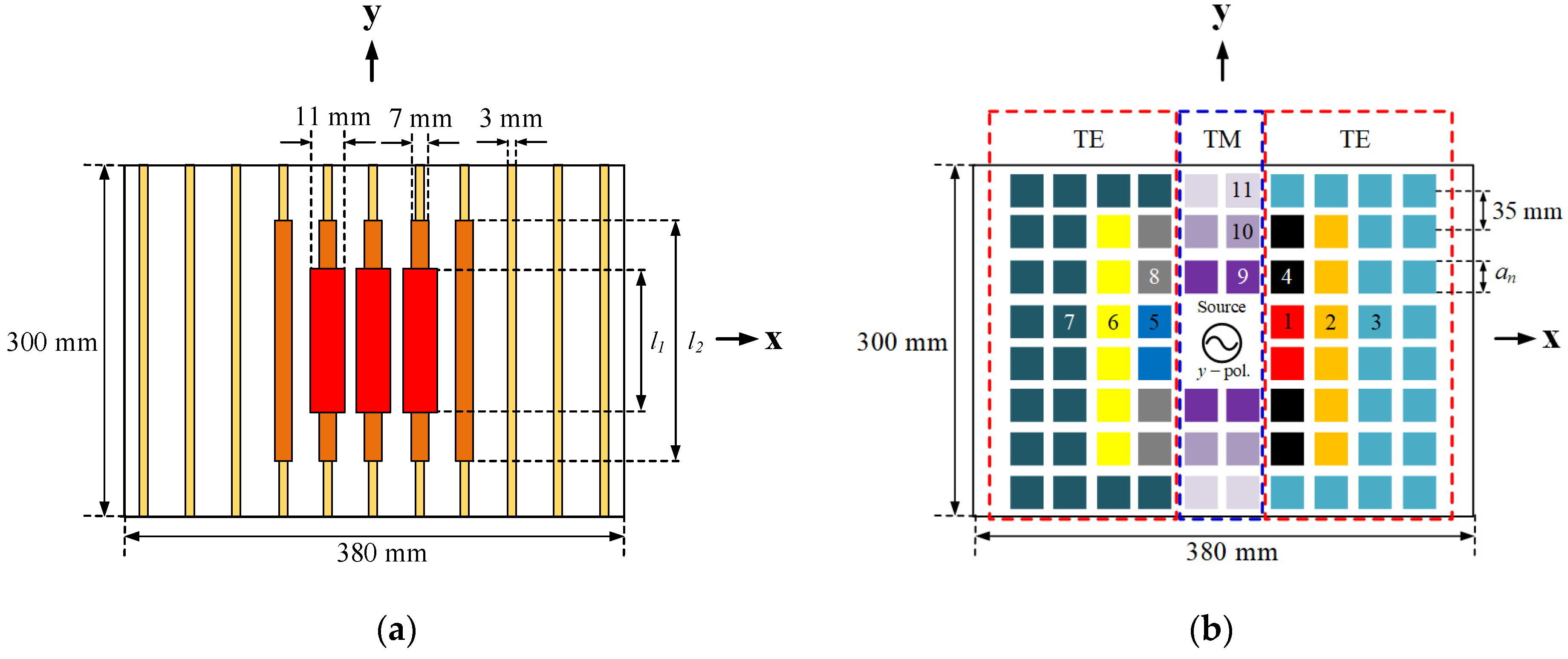
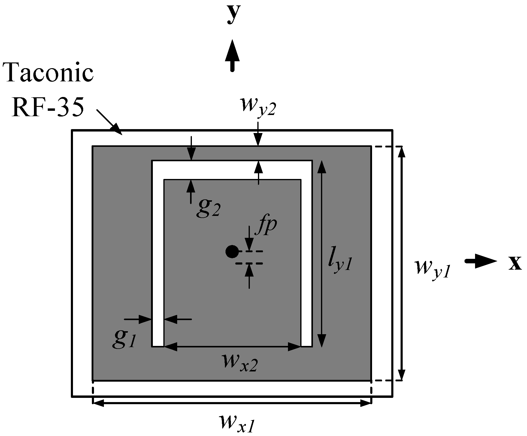
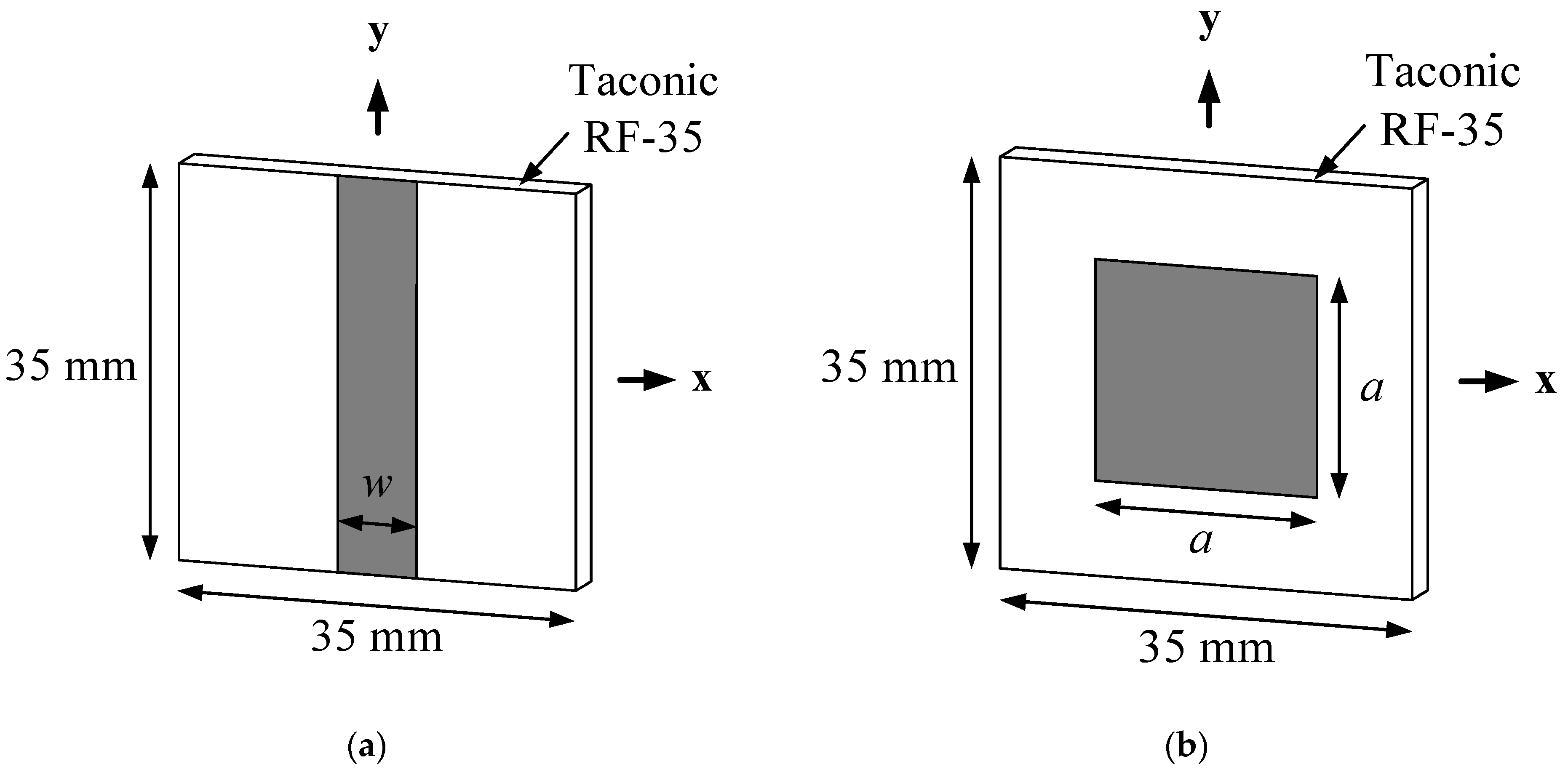
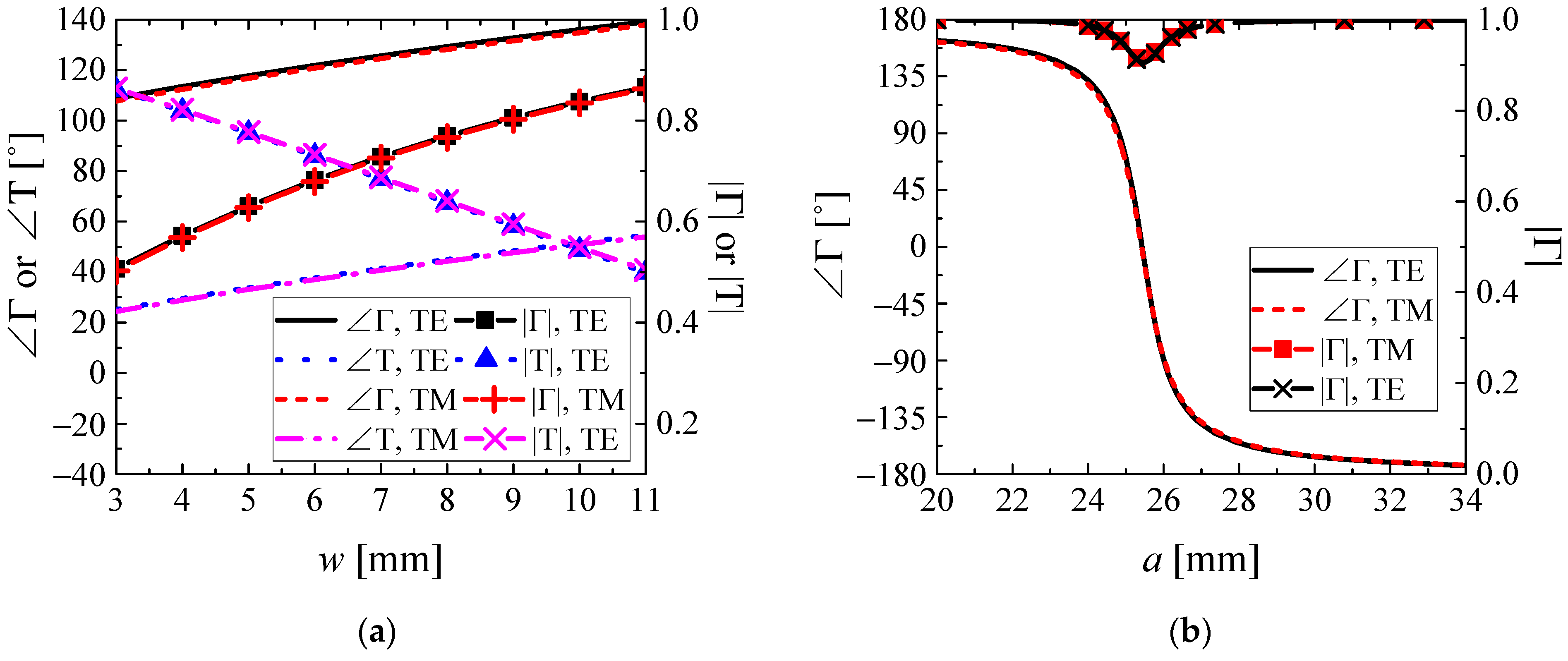
2.3. Design of the AMC and the PRS Unit Cell

Figure 6 represents the configuration of the PRS and the AMC unit cell. Both of them employ a Taconic RF-35 substrate of thickness 1.52 mm with dielectric constant εr = 3.5 and loss tangent tan δ = 0.0025. The PRS cell consists of a copper strip parallel to the y-axis and a fully etched opposite backside. On the other hand, the AMC cell is comprised of a square patch etched on the substrate whose backside is entirely covered with copper. In both cells, the required reflection or transmission phases can be obtained by changing the widths of the patches (w and a in Figure 6).
The unit cell simulations for two different incident modes of a transverse electric (TE) and a transverse magnetic (TM) with the incidence angle α are illustrated in Figure 7. As briefly aforementioned in Section 2.1, when determining the reflection or transmission phases of the PRS and the AMC cell, we should take into account both the incident angle and polarization. In our antenna, the incidence angle is fixed at 19° by the antenna height h = 50 mm and the unit cells’ period p = 35 mm. When it comes to the incident polarization, we have supposed that a TE field is incident on the cells in the region surrounded by the red lines in Figure 4, whereas a TM field is incident in the region enclosed by the blue lines according to the y-polarized feeder antenna.
The reflection or the transmission coefficients of the proposed PRS and the AMC unit cell are plotted in Figure 8. As the incidence angle is low enough, the reflection and transmission behaviors are pretty similar to each other. When we see the reflection phases, we can confirm that the AMC has much wider phase coverage than the PRS, which is favorable for various beam-scan directions. Moreover, the reflection magnitudes of the PRS are varied from 0.50 to 0.86 while those of the AMC are maintained as fairly high from 0.9 to 1.0, which are desirable to reduce an SLL and to obtain high gain, respectively.

3. Results

To prove the proposed beam-scan method in an FPC antenna, we fabricated and measured a prototype antenna for a scanned beam at θ = 30˚ and ϕ = 0˚, which is presented in Figure 9. The total volume of the antenna excluding the four acrylic supports measures 380 mm × 300 mm × 53.04 mm. Here, we could not help but fabricate the y-axis length shorter than that of the x-axis due to the limited fabrication facilities. However, it does not matter for proving our idea because the antenna is designed to scan the beam on the xz-plane (ϕ = 0˚) where the x-axis length plays a crucial role rather than that of the y-axis.
Impedance matching results for different scan angles are plotted in Figure 10. To confirm that our idea is still valid for other beam-scan directions but θt = 30°, we have conducted additional simulations for θt = 0°, θt = 15°, and θt = 45°. As shown in Figure 10, the −10 dB bandwidths are well maintained for the most cases. However, we can find that the impedance matching is slightly deteriorated for θt = 45°. This is owing to the large variation of reflection phases of AMC cells compared to the other cases, which needs to be further improved in future works. A little discrepancy between the simulated and the measured results for θt = 30° is caused by the limited fabrication tolerance, which is significantly influential for our antenna.
Three-dimensional radiation patterns of the proposed antenna for each target direction are also shown in Figure 11. As we can see, the FPC antenna can scan the main beam well by properly adjusting the AMC configurations. To show the beam-scan performance more clearly, we plotted the contours of the radiation patterns on both the H- and E-plane for each scanning case in Figure 12. The specific performances of the proposed antenna at the design frequency are summarized in Table 2. As is described, the antenna can scan the main beam in the target direction with well-maintained high gain and a relatively narrow half-power beamwidth (HPBW). Good agreement between expected and experimental results verifies the validity of our design approach.
A comparison between previous works and own is described in Table 3. Even though [11,12] can scan the main beam continuously, they are hardly applicable for real time-varying systems due to their phase-adjusting methods: mechanically rotating a PRS and injecting water into a PRS. Moreover, while [13,14,15] can electrically switch the main beam using PIN-diodes, they cannot realize continuous beam-scanning and a wide steering coverage. On the other hand, our work can electrically and continuously scan the main beam with high gain as well as a wide scan range by introducing the phase-controllable AMC ground plane, which is far favorable for commercial applications.

4. Conclusions

In this paper, we have proposed a novel beam-scan method in an FPC antenna providing relatively high gain with a low SLL obtained using a tapered PRS. In order to produce the desired tilted main beam, an AMC ground plane was newly introduced, which was easier and more practical to manipulate the reflection phase than modifying PRS cells. In that only changing the AMC’s reflection property is enough to produce a scanned beam, our approach is innovative compared with previous works.
To verify the proposed method, we have performed several simulations for different beam-scan directions and measured the fabricated prototype antenna. Accordingly, we have successfully proved that the proposed antenna indeed provides a well-directed beam in the desired target directions with reasonably high gain.
Although we have shown only a fixed tilted beam, our method can readily expand to electrical beam-scanning applications by employing active RF components in the AMC cells. In addition, our work has also presented a good idea of separating bias networks from a crucial field-bouncing cavity area. Therefore, in the active scanning approach, the expected potential problems that the bias lines will disturb a sensitive cavity mode are already removed. Consequently, we expect our method can be utilized in many practical beam-scan applications that require beam-scanning as well as high gain.

Author Contributions

Formal analysis, W.J. and D.K.; Funding acquisition, J.K.; Investigation, W.J., H.-j.M. and D.K.; Methodology, W.J., Y.-g.J., H.-j.M. and D.K.; Supervision, D.K.; Validation, W.J., Y.-g.J. and H.-j.M.; Writing—original draft, W.J.; Writing—review & editing, Y.-g.J. and D.K. All authors have read and agreed to the published version of the manuscript.

Funding

This research has been supported by a grant-in-aid of HANWHA SYSTEMS based on the Defense Challengeable Future Technology Program of ADD.

Institutional Review Board Statement

Not applicable.

Informed Consent Statement

Not applicable.

Data Availability Statement

Data sharing not applicable.

Conflicts of Interest

The authors declare no conflict of interest.

References

  1. Kim, J.O.; Yoon, W.S.; Han, S.M. Frequency-Selective Beamforming Array Antenna Systems with Frequency-Dependent Phase Shifters. J. Electromagn. Eng. Sci. 2019, 19, 259–265. [Google Scholar] [CrossRef] [Green Version]
  2. Mao, C.; Gao, S.; Wang, Y. Broadband High-Gain Beam-Scanning Antenna Array for Millimeter-Wave Applications. IEEE Trans. Antennas Propag. 2017, 65, 4864–4868. [Google Scholar] [CrossRef]
  3. Nayeri, P.; Yang, F.; Elsherbeni, A.Z. Beam-Scanning Reflectarray Antennas: A technical overview and state of the art. IEEE Trans. Antennas Propag. Mag. 2015, 57, 32–47. [Google Scholar] [CrossRef]
  4. Huang, J.; Encinar, J.A. Reflectarray Antennas, 1st ed.; Wiley: Hoboken, NJ, USA, 2008. [Google Scholar]
  5. Sievenpiper, D.F.; Schaffner, J.H.; Song, H.J.; Loo, R.Y.; Tangonan, G. Two-dimensional beam steering using an electrically tunable impedance surface. IEEE Trans. Antennas Propag. 2003, 51, 2713–2722. [Google Scholar] [CrossRef] [Green Version]
  6. Trentini, G.V. Partially reflecting sheet arrays. IRE Trans. Antennas Propag. 1956, 4, 666–671. [Google Scholar] [CrossRef]
  7. Lalbakhsh, A.; Esselle, K.P. Directivity improvement of a Fabry-Perot cavity antenna by enhancing near field characteristic. In Proceedings of the 17th International Symposium on Antenna Technology and Applied Electromagnetics, Montreal, QC, Canada, 10–13 July 2016; pp. 1–2. [Google Scholar]
  8. Lalbakhsh, A.; Afzal, M.U.; Esselle, K.P.; Smith, S.L. Low-Cost Nonuniform Metallic Lattice for Rectifying Aperture Near-Field of Electromagnetic Bandgap Resonator Antennas. IEEE Trans. Antennas Propag. 2020, 68, 3328–3335. [Google Scholar] [CrossRef]
  9. Lee, J.G. Compact and robust Fabry-Perot cavity antenna with PEC wall. J. Electromagn. Eng. Sci. 2021, 21, 184–188. [Google Scholar] [CrossRef]
  10. Guo, Q.-Y.; Lin, Q.W.; Wong, H. A High Gain Millimeter-Wave Circularly Polarized Fabry–Pérot Antenna Using PRS-Integrated Polarizer. IEEE Trans. Antennas Propag. 2021, 69, 1179–1183. [Google Scholar] [CrossRef]
  11. Afzal, M.U.; Matekovits, L.; Esselle, K.P.; Lalbakhsh, A. Beam-Scanning Antenna Based on Near-Electric Field Phase Transformation and Refraction of Electromagnetic Wave Through Dielectric Structures. IEEE Access 2020, 8, 199242–199253. [Google Scholar] [CrossRef]
  12. Naqvi, A.H.; Lim, S. A Beam-Steering Antenna with a Fluidically Programmable Metasurface. IEEE Trans. Antennas Propag. 2019, 67, 3704–3711. [Google Scholar] [CrossRef]
  13. Xie, P.; Wang, G.; Li, H.; Liang, J. A Dual-Polarized Two-Dimensional Beam-Steering Fabry–Pérot Cavity Antenna with a Reconfigurable Partially Reflecting Surface. IEEE Antennas Wirel. Propag. Lett. 2017, 16, 2370–2374. [Google Scholar] [CrossRef]
  14. Ji, L.; Guo, Y.J.; Qin, P.; Gong, S.; Mittra, R. A Reconfigurable Partially Reflective Surface (PRS) Antenna for Beam Steering. IEEE Trans. Antennas Propag. 2015, 63, 2387–2395. [Google Scholar] [CrossRef]
  15. Ji, L.; Zhang, Z.; Liu, N. A Two-Dimensional Beam-Steering Partially Reflective Surface (PRS) Antenna Using a Reconfigurable FSS Structure. IEEE Antennas Wirel. Propag. Lett. 2019, 18, 1076–1080. [Google Scholar] [CrossRef]
  16. Jopek, Ł.; Hausman, S.; Di Barba, P. Optimization of an Artificial Magnetic Conductor Geometry Using a Paretian Approach. In Proceedings of the 2019 13th European Conference on Antennas and Propagation (EuCAP), Krakow, Poland, 31 March–5 April 2019; pp. 1–5. [Google Scholar]
  17. Niaz, M.W.; Yin, Y.; Zheng, S.; Zhao, Z. Dual-polarized low sidelobe Fabry-Perot antenna using tapered partially reflective surface. Int. J. RF Microw. Comput. Aided Eng. 2020, 30, e22070. [Google Scholar] [CrossRef]
  18. CST Microwave Studio. Available online: http://www.cst.com/ (accessed on 17 November 2021).
  19. Lalbakhsh, A.; Afzal, M.U.; Esselle, K.P.; Smith, S.L.; Zeb, B.A. Single-Dielectric Wideband Partially Reflecting Surface with Variable Reflection Components for Realization of a Compact High-Gain Resonant Cavity Antenna. IEEE Trans. Antennas Propag. 2019, 67, 1916–1921. [Google Scholar] [CrossRef]
  20. Abdelrahman, A.H.; Elsherbeni, A.Z.; Yang, F. Transmission Phase Limit of Multilayer Frequency-Selective Surfaces for Transmitarray Designs. IEEE Trans. Antennas Propag. 2014, 62, 690–697. [Google Scholar] [CrossRef]
  21. Dewan, R.; Rahim, M.K.A.; Hamid, M.R.; Yusoff, M.F.M.; Samsuri, N.A.; Murad, N.A.; Kamardin, K. Artificial magnetic conductor for various antenna applications: An overview. Int. J. RF Microw. Comput. Aided Eng. 2017, 27, e21105. [Google Scholar] [CrossRef]
Figure 1. Overviews of (a) the proposed FPC antenna that can scan the main beam on the xz-plane (ϕ = 0°) and (b) its beam-scanning scenarios.
Applsci 11 11005 g001
Figure 2. Beam-scanning principles of (a), a conventional FPC antenna, and (b) the proposed FPC antenna. To obtain a directional beam in the target direction, transmitted fields should be in-phase on the target wavefront.
Applsci 11 11005 g002
Figure 3. Overviews of FPC antennas consisting of (a) an active PRS and (b) an active AMC. It is desirable for the bias lines to be placed beneath the ground plane as they hardly affect the FP resonance in the cavity.
Applsci 11 11005 g003
Figure 4. Deployment of (a) the tapered PRS superstrate and (b) the AMC ground plane. The design parameters of the PRS are l1 = 105 mm and l2 = 175 mm. Each length of the AMC cell an is determined for a scanned beam in the target direction θt = 30°, and is listed in Table 1.
Applsci 11 11005 g004
Figure 5. The U-slot microstrip patch antenna used as a source antenna. The design parameters are wx1 = 30 mm, wx2 = 15 mm, wy1 = 25.5 mm, wy2 = 1 mm, ly1 = 20 mm, g1 = 1 mm, g2 = 2 mm, and fp = 3 mm.
Applsci 11 11005 g005
Figure 6. The geometry of each unit cell of (a) the PRS and (b) the AMC, respectively. Their reflection and transmission coefficients depend on the parameters w and a.
Applsci 11 11005 g006
Figure 7. Unit cell simulations for two different incident modes of (a) a transverse electric (TE) and (b) a transverse magnetic (TM) with the incidence angle α.
Applsci 11 11005 g007
Figure 8. Reflection and transmission coefficients of (a) the PRS and (b) the AMC cell. All characteristics are obtained at the design frequency.
Applsci 11 11005 g008
Figure 9. (a) The fabricated FPC antenna that consists of the PRS superstrate and the AMC ground plane with four acrylic supports and (b) its measurement environment.
Applsci 11 11005 g009
Figure 10. Input reflection coefficients (S11) according to the frequency for each scanned beam case.
Applsci 11 11005 g010
Figure 11. Simulated 3D radiation patterns for each scanned beam at the designed frequency. All target directions are on the xz-plane (ϕ = 0°): (a) θt = 0°, (b) θt = 15°, (c) θt = 30°, and (d) θt = 45°.
Applsci 11 11005 g011
Figure 12. Radiation patterns for different target directions θt = 0°, 15°, 30° and 45° on the (a) H-plane and (b) E-plane. All results are obtained at the design frequency.
Applsci 11 11005 g012
Table 1. Lengths an (mm) of each AMC cell determined for a scanned beam in θt = 30°.
nth AMC CellLength [mm]
122.53
227.61
327.57
427.24
525.88
625.56
725.56
825.53
925.84
1025.99
1125.98
Table 2. Simulated performance parameters of the proposed antenna.
Beam Scanning
Angle
[°]
Realized Gain
[dBi]
Sidelobe Level
[dB]
Half-Power Beamwidth
[°]
E-PlaneH-PlaneE-PlaneH-Plane
11.8−14.1−19.24536
15°11.4−13.1−18.34336
30°13−18.1−12.83434
41°10.6−8−7.12340
Table 3. Performance comparison of beam-steering FPC antennas.
Ref. # 1Beam Scanning
Type
Beam Scanning Angle 2
[°]
Gain
[dBi]
[11]Continuous1–3912.2–16.0
[12]Continuous±204.67–8.53
[13]Discrete0, ±1011.9–12.0
[14]Discrete0, ±1511.7–16.3
[15]Discrete0, ±229.6–10.4
This workContinuous±4110.6–13.0
1 ‘#’ means the reference number. 2 on the elevation angles.
Publisher’s Note: MDPI stays neutral with regard to jurisdictional claims in published maps and institutional affiliations.

