Article

Hydraulic Fracture Propagation Near the Cavity in a Poroelastic Media

Chinakal Institute of Mining SB RAS, 630091 Novosibirsk, Russia
*
Author to whom correspondence should be addressed.
Appl. Sci. 2021, 11(22), 11004; https://doi.org/10.3390/app112211004
Submission received: 16 October 2021 / Revised: 15 November 2021 / Accepted: 17 November 2021 / Published: 20 November 2021
(This article belongs to the Special Issue Evaluation of Geomechanical Characteristics)

Abstract

:
In this paper, we investigate the problem of the propagation of hydraulic fractures in a poroelastic medium that has a circular cavity. The research was conducted using the extended finite element method (XFEM) implemented in the ABAQUS software package. The problem was considered in a plane formulation. The initial crack was oriented parallel to the surface of the cavity. It was shown that the path of the hydraulic fracture depends strongly on the hydrostatic stress in the medium and the distance between the crack and the cavity. We studied the influences of the poroelastic parameters, such as permeability and the Biot coefficient, on the propagation of cracks. It was shown that the cracks were less curved when the coupled problem of poroelasticity was considered. The features of fluid pressure changes inside the fracture and at the opening of the mouth were studied. It was shown that the fluid pressure in the fracture during injection was minimally sensitive to the state of the stress in the medium, to the position of the initial crack, and to the poroelastic parameters. The solution to the problem in this setting can be used to simulate hydraulic fracturing close to mine workings during a controlled roof’s collapse to prevent it from hanging, and the formation of impervious screens to reduce airflow from the mine to degassing boreholes through the rock, for example.

1. Introduction

Hydraulic fracturing (HF) is used extensively to increase production in the oil and gas industry as well as for solving various problems associated with mining, underground construction, and the management of nature. The idea behind HF, which is relatively simple to implement, has led to its widespread adoption. It has been applied in projects related to the recovery of heat from geothermal sources [1,2,3,4], the storage of carbon dioxide [5,6,7], underground bioleaching [8,9], and the disposal of drill cuttings and waste materials [10,11]. This emphasizes the importance of preparatory work on planning HF operations for the formation of fractures of a given direction, including the construction and analysis of adequate mathematical models.
The main research areas of the mine modification of the method are associated with improving the safety of underground operations. When mining coal seams, HF is used to increase the efficiency of the production of methane from coal by increasing the gas recovery [12,13,14] and creating impervious protective screens in the rock mass near mine workings [15,16]. In the case of the extraction of coal seams by longwall mining, hydraulic fracturing is applied for the controlled roof’s collapse to prevent it from hanging [17,18,19]. This method has many variations for in situ stress measurement based on the analysis of breakdown, shut-in, and reopening pressures [20,21,22]. This helps to control the integrity of the mine’s walls and in planning further activity.
Calculations of the paths of cracks during their propagation are critical for the design of inseam hydraulic fracturing in the underground environment. Modeling errors that occur at this stage can lead to undesirable consequences, i.e., the emergence of cracks in the sides of the working, intersection with adjacent wells, and uncontrolled destruction of the massif.
There are several factors that have significant impacts on the development of fractures. These factors include the stress-strain state of the rock mass, the condition of the borehole walls (presence of casing and perforations) and their directions, the characteristics of the loading that is being applied, i.e., the design and other features of the downhole tool, the rate of injection of the fracturing fluid, and the properties of the fracturing fluid, as well as the location of the crack relative to mine workings.
Modern directions of research are related to the development and verification of the analytical and numerical models of the propagation of hydraulic fractures. Various analytical models are used, including the Kristianovic, Geertsma, and de Klerk (KDG) Model [23,24], the Perkins, Kern and Nordgren (PKN) Model [25,26], and some variations of these models. Despite the fact that these models are based on the assumption of a non-varying and homogeneous stress field, they are suitable for quick analyses, and they allow improvements in numerical methods and approaches. In contrast, numerical models based on various techniques, such as the boundary element method (BEM) [27], the discrete element method (DEM) [28], the finite element method (FEM) [29], and damage mechanics-based approaches [30,31,32] can take into account, for example, the complex geometry of hydraulic fractures under excavation stress conditions.
The propagation of cracks close to hollow inclusions has been considered in several studies, some of which were related to modeling the hydraulic fracture phenomenon near underground work areas. A two-dimensional model for the HF of the roof in the stope was established to investigate the crack-growth features [33]. The numerical simulation was based on the 8203 working face of the Datong Coal Mine in China as the prototype. The results that were obtained showed that the deflection angle of the hydraulic fracture increases as the mining width increases, but it decreases as the side pressure coefficient and the fractured horizon increase. Another model and solution results in the problem’s planar formulation of the hydraulic fracture propagation in the coal seam in the vicinity of the mines were considered in [34]. It was shown that the stress field is important because it can have a significant effect on the path of the crack under certain conditions. Liu et al. applied a phase field method (PFM) to simulate the propagation of a hydraulic fracture close to the cavity, and they verified the results by comparing them with previously published experimental data that were derived from cubic samples made of concrete [35]. Chen et al. investigated the effect of the condition of the excavation stress on the behavior of cracks using a flow-coupled DEM while performing single-stage and multi-stage HF [36]. The results of the numerical simulation indicated that the in situ stresses and the location of the injection have major influences on the propagation of the HF.
Some papers have investigated the situation in which the path of the crack was directed from the medium towards the cavity. The relevance of the problem is associated with two main areas of research:
  • existing possibility of natural and artificial cracks emerging into the working, which can disrupt its integrity and possibly stop the underground activity;
  • carbonate oil and gas reservoirs, which contain abundant natural fractures and cavities and have great potential for development via hydraulic fracturing.
The behavior of a hydraulic fracture near a mine in a plane-parallel formulation was investigated in [37]. It was shown that, when the hydrostatic pressure increases with respect to critical tensile stress, the fracture begins to deviate from the mine opening earlier and does not reach its surface. Zhao et al. developed an extended finite element model (XFEM) for the propagation of HF in fracture-cavity reservoirs that can be used to simulate the extension of cracks in cases of a single cave and a single natural fracture [38]. The results indicated severe stress concentrations near caves, resulting in deflections of the predominant propagation direction of the crack.
Another factor that can affect the trajectory of the propagation of a crack is the poroelastic properties. It was shown that the lengths and openings of cracks in a poroelastic medium, as well as the fracturing pressure, can differ significantly from the values obtained in the elastic model [39]. It was indicated that the trajectories of cracks near the free surface in elastic and poroelastic media differ from each other [40]. A fully coupled fluid flow and geomechanics model for the growth of hydraulic fractures in the near-wellbore region was validated against the experimental results presented in [41]. Wang et al. developed a poro-elasto-plastic HF model that allows the estimation of the growth of fractures by considering the effects of the cohesive zone and the plastic deformation in the bulk formation [42]. Zeng et al. studied the effects of poroelastic properties and permeability on hydraulic fracturing in an anisotropic medium [43]. The analysis and experimental results of the initiation and propagation of tensile fractures in different pore pressure fields were presented in [44]. It was noted that the magnitude of the local pore pressure contributed directly to the energy available for the fracture. Later, Wang et al. applied the RFPA2D code to simulate the hydraulic fracturing mechanism in rock and compared the results with laboratory tests [45]. He et al. used the XFEM code for these same purposes [46]. The process of the propagation of a hydraulic fracture was simulated using different geo-stress conditions, and the effects of rock heterogeneity, the pore-fluid pressure coefficient, and the pore-pressure gradient on the occurrence of hydraulic fracturing were investigated [47].
In this paper, we investigated the development of a hydraulic fracture in a poroelastic medium that contained a circular cavity and was uniformly compressed at infinity. The solution to the problem in this setting can be used to simulate hydraulic fracturing close to mine workings and improve the efficiency and safety of underground operations. The problem was considered in a plane formulation, and numerical modeling was performed using the XFEM implemented in the ABAQUS software package.

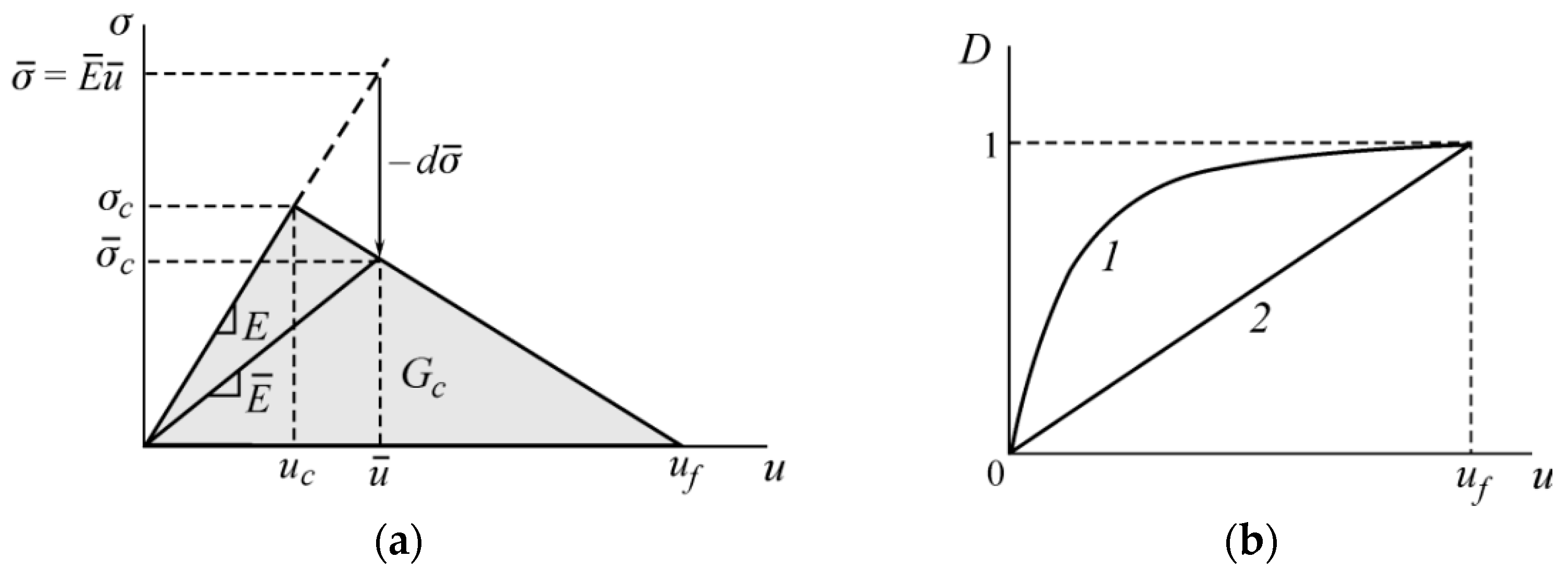
2. Basic Equations of the Model

Let us consider the problem of crack propagation in a homogeneous poroelastic medium, the deformations of which are determined by the following equations:
σ i j = 2 μ ε i j + λ ε 0 δ i j α p δ i j
where σij is the solid body stress tensor; ε i j = ( u i / x j + u j / x i ) / 2 is the solid body strain tensor; ui are the body displacements; λ, μ are the Lame parameters of dry rock; ε0 is the volume strain; p is the fluid pressure within the poroelastic body; and α is the Biot coefficient. The fluid flow in a porous medium is determined by the continuity equation:
1 M p ˙ + α ε ˙ k k + v k , k = 0
where M is the Biot modulus, and v is the fluid flow velocity. The coefficients α and M can be determined through the modulus of volumetric compression of the fluid Kf, the modulus of volumetric compression of the solid phase (skeleton) Ks, the modulus of volumetric compression of the porous medium K and porosity γ:
1 M = γ K f + α γ K s ,         1 K s = 1 α K
Filtration of the fluid through a porous medium is specified by Darcy’s law:
v i = k η p i
where k is the medium permeability, and η is the dynamic viscosity of the fluid.
The fluid flow in the fracture was described by the continuity equation:
d t + · q + v t + v b = 0
where d is the crack opening; q = ( q 1 , q 3 , q 2 ) ; q i = d k ˜ ( p / x i ) ; k ˜ is the effective permeability of the crack in the ith direction; vt and vb are the rates of fluid leakage into the formation through the upper and lower crack surfaces. Within the problem under consideration we believe that the fluid flow inside the crack is Poiseuille flow, and the fluid is Newtonian. Thus, the effective fracture permeability can be defined as:
k ˜ = d 2 12 η
In the process of modeling we assume that the fluid flowing in the fracture and the fluid filtered in the porous medium are the same.
Crack propagation modeling is done using the Cohesive Zone Model (CZM) approach [48]. It is assumed that there is a softening zone of the material formed right before the fracture. In this zone, stresses σ occur, and they are associated with displacements u according to a certain law. Two parameters are required to determine the law, i.e., σc and GIc. The parameter σc is the critical stress, and GIc is the critical energy release rate during fracturing, which is calculated as:
G I c = 0 u f σ d u
where uf is the displacement discontinuity that corresponds to the total destruction of the material.
In the case in which the cohesive failure zone is small compared to the length of the crack, the stress intensity factor and the critical energy released in failing are related by the formula [49]:
K I c = G I c E 1 υ 2
where E is the elasticity modulus of the material.
The destruction of the rock starts when the critical stress, σc, is attained. Then, new values of the critical stress, σ ¯ c , and the elastic modulus, E ¯ , are calculated, according to the specified nature of the fracture, which is determined by the fracture variable D(u), which depends on the deformations outside the linear elastic zone. Figure 1b shows an example of the function D(u), where D = 0 corresponds to the intact state, and D = 1 corresponds to complete damage.
The ratios described above that determine the behavior of a rock with a crack were solved numerically using the XFEM, implemented in the ABAQUS software package. The XFEM allows one to obtain solutions that contain a displacement jump using discontinuous functions, and solutions near the apex of the crack can be found using special asymptotic functions. This method can be used to model the initiation and propagation of the crack in the direction that is determined from the analysis of the stress state in the vicinity of the crack tip, which can be of any kind.
The used XFEM implementation also has several disadvantages. For example, a crack can split a finite element only completely in a straight line, i.e., the crack tip cannot be inside the element; it also cannot change the direction while passing through the element. In addition, the crack is not allowed to turn more than 90° in one increment during analysis. The crack intersection/branching cannot be simulated.

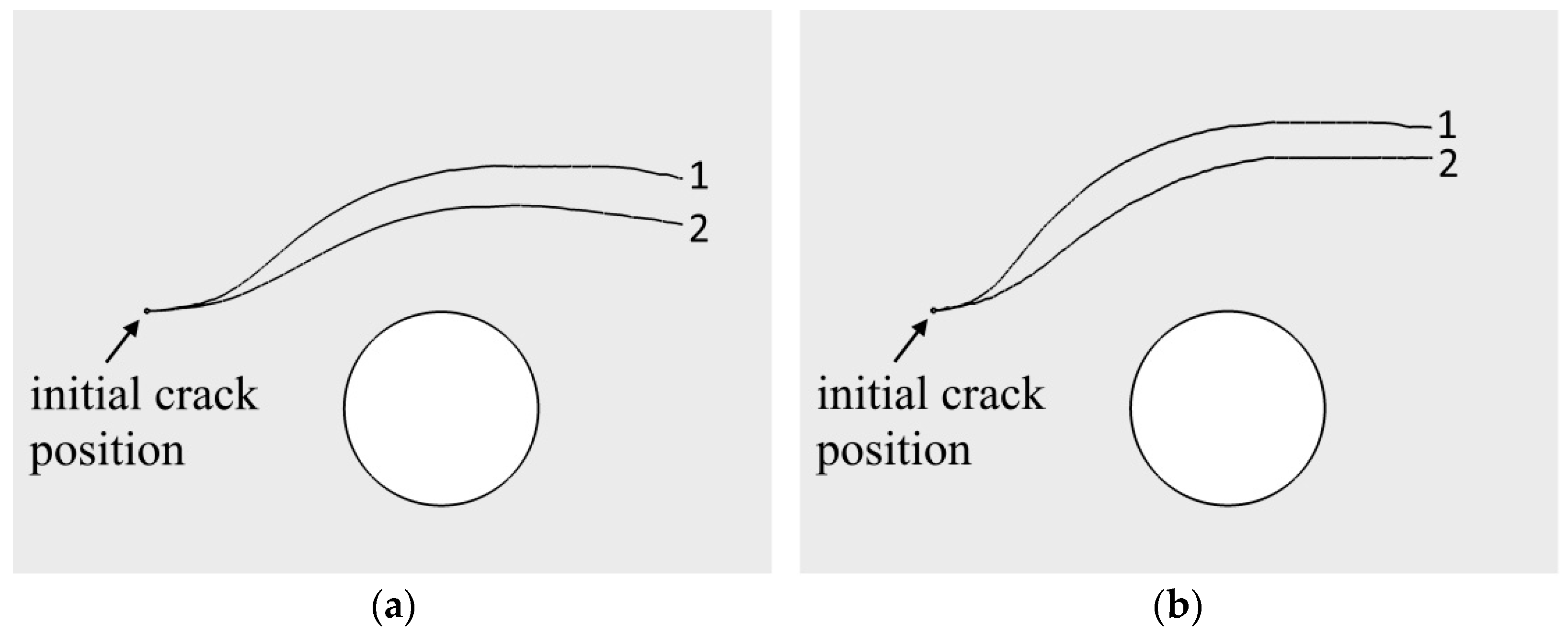
3. Numerical Test Results and Discussion

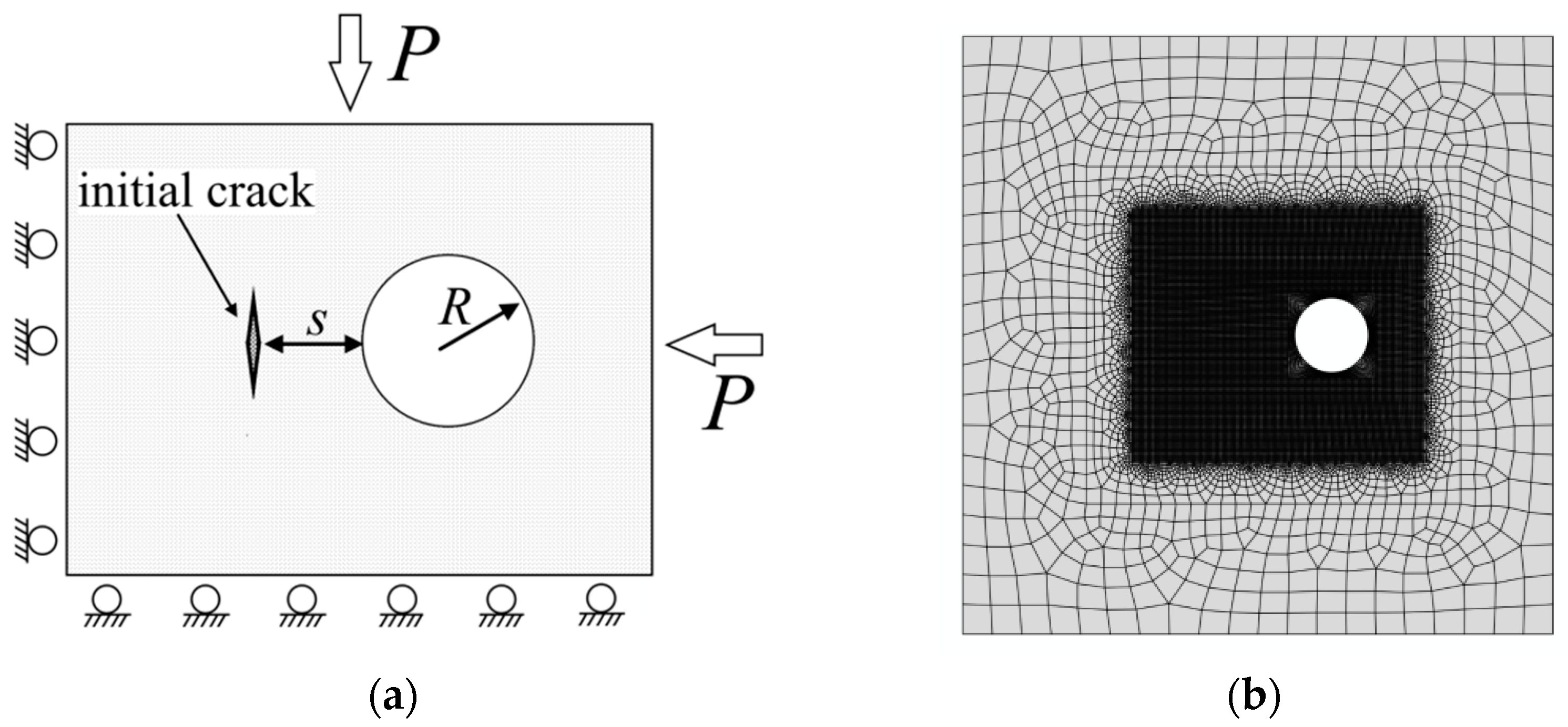
3.1. Formulation of the Problem

Let us consider the problem of interaction between a hydraulic fracture and a circular cavity in a plane formulation. Figure 2 shows a 2D area with a circular cavity that has a radius, R. The initial crack is located at a distance, s, from the surface of the cavity and is oriented vertically.
In numerical experiments, the size of the area is 40 × 40 m, and the radius of the cavity is 2.5 m. Figure 2 shows the position of the cavity and the discretization of the area. The minimum element size is 0.1 m. On the outer boundary of the area, we set the conditions providing hydrostatic compression, P, in the vicinity of the cavity (Figure 2a). The boundary of the circular cavity is free. For numerical calculations we define the following parameters: the elasticity modulus of the rock, E = 3.0 GPa; Poisson’s ratio, υ = 0.3; dynamic viscosity of the fluid, η = 0.001 Pa·s; critical energy release rate, GIc = 280 N/m; critical stress, σc = 0.75 MPa; fluid injection rate into the crack, q = 0.001 m2/s, and porosity, γ = 0.1. The medium permeability, k, Biot coefficient, α and Biot modulus, M, are changed during the calculations.

3.2. Uncoupled Problem

In the first numerical experiment, an uncoupled problem, i.e., α = 0 is considered. In this case, the results of modeling the hydraulic fracturing correspond to the solutions obtained in the elastic model. Some aspects of such a problem already have been studied [35,37,50]. Figure 3 shows the paths of the hydraulic fractures at different hydrostatic stresses, P, and different distances between the initial crack and the cavity. The distance between the initial crack and the cavity, s, is different, i.e., s = 0.5 R, s = R, s = 2 R. The hydrostatic stress in the medium, P, is equal to 0, 1.5, and 6 MPa. In Figure 3, number 1 denotes the curve obtained at P = 0 MPa, number 2 denotes the curve at P = 1.5 MPa, and number 3 denotes the curve at P = 6 MPa. Since the computational area is under hydrostatic compression, the problem is symmetric to the axis normal to the initial crack and passing through its center. Therefore, when calculating and displaying the results, we use only one of the symmetric planes shown in Figure 3. It can be seen that the cavity has a strong influence on the paths of the hydraulic fracturing, and they are different from straight lines. The main reason for the curvature of the cracks is associated with the stresses arising around the cavity under hydrostatic loading. As the hydrostatic stress increases, the fracture path becomes more curved. Also, when the initial crack is placed closer to the circular cavity, the influence of the stress around the cavity is enhanced.
The paths of the cracks also are influenced by the parameters of the medium. Figure 4a,b show the paths of the cracks for different values of the critical tensile stress, σc, and the elastic modulus E. It is seen that, as σc and E increase, the effect of the cavity decreases, and the cracks are less curved. Changes in the other parameters of the medium, such as the critical energy release rate, GIc, Poisson’s ratio, υ, and the dynamic viscosity of the fluid, η, do not lead to significant changes in the directions of the development of the fracture and are not presented in the article.

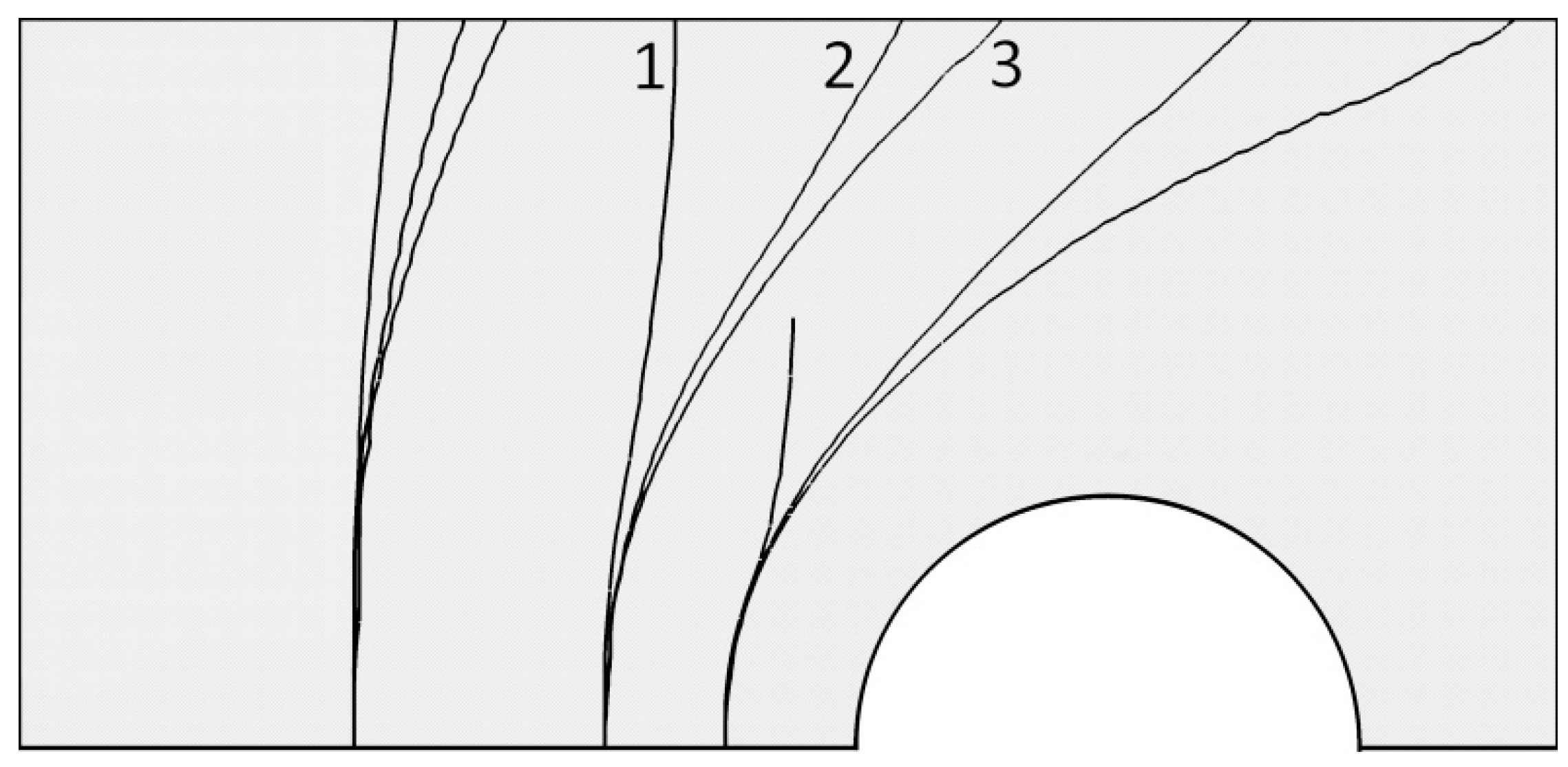
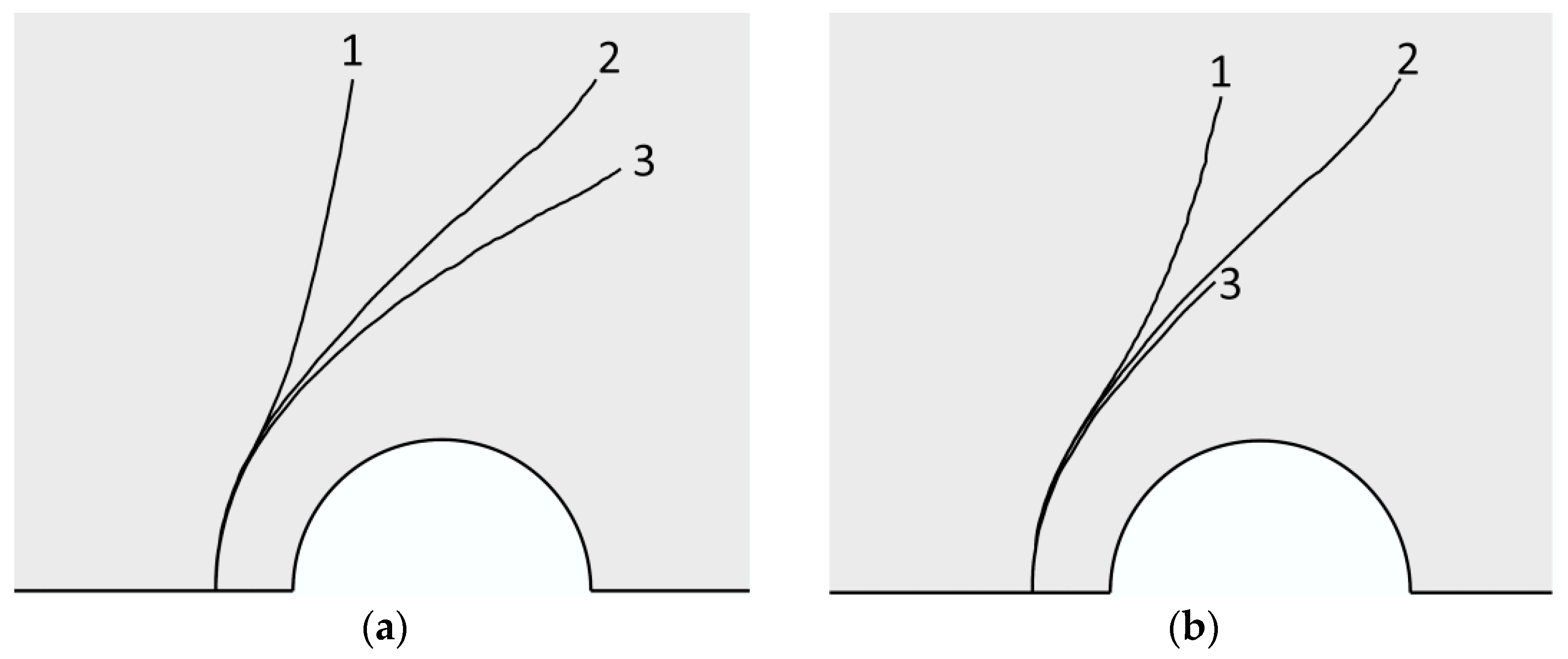
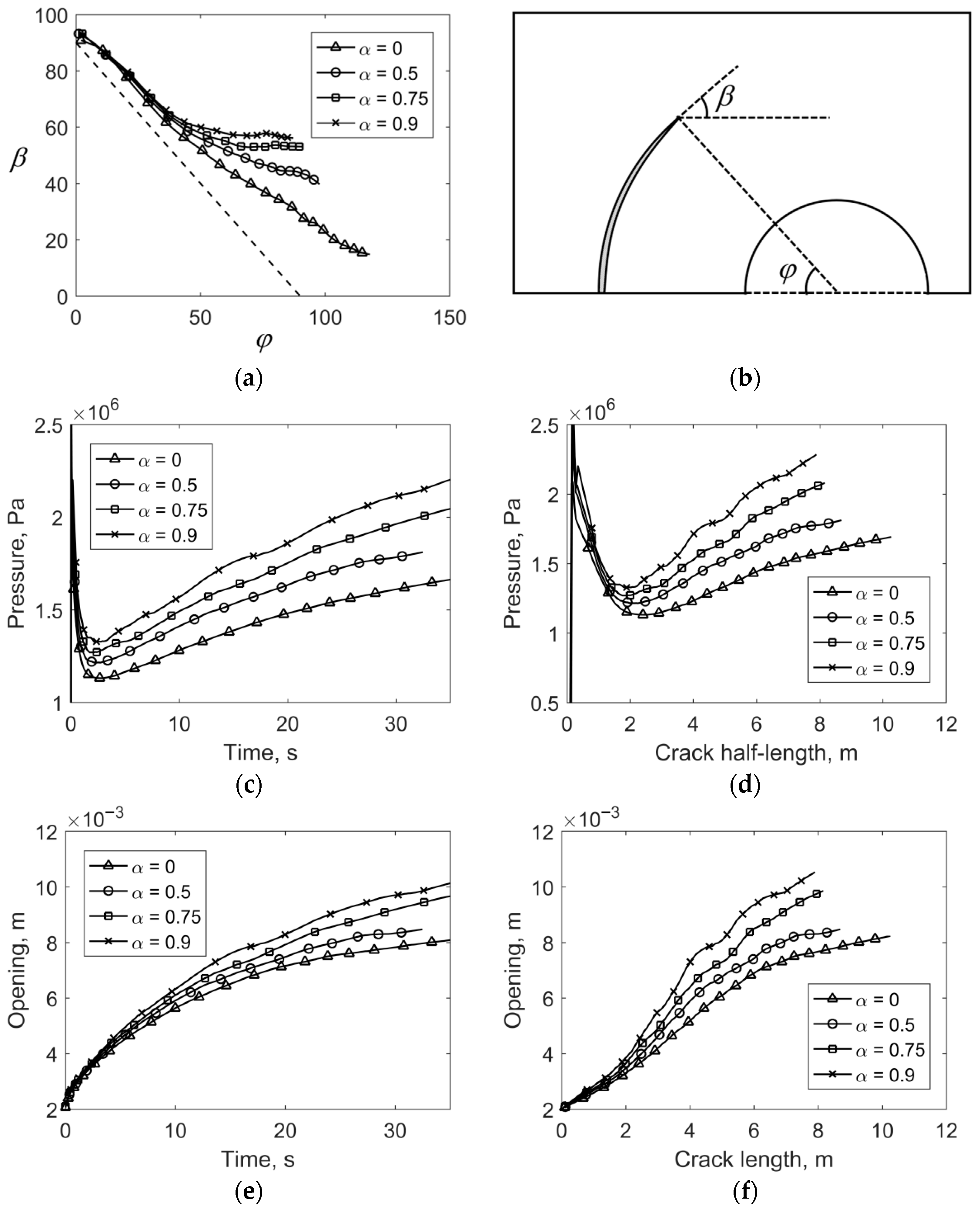
3.3. Influence of Poroelastic Parameters on Hydraulic Fracturing

Next, we consider the influence of the poroelastic parameters on the crack propagation path using the following example. Let the initial crack be oriented parallel to the surface of the circular cavity (Figure 5a) and located at a distance equal to half the radius of the cavity (s = 0.5 R). In the first numerical experiment, the influence of the Biot coefficient, α, on the crack propagation has been investigated at a constant medium permeability, i.e., k = 1 μm2, and a constant hydrostatic stress, P, equal to 1.5 MPa. The value of α determines the degree of mutual influence of the stress-strain state of the solid phase and the pore pressure of the fluid. The value α = 0 corresponds to a fully uncoupled problem (i.e., the pore pressure and the stressed state of the medium do not affect each other), and α = 1 corresponds to a fully coupled problem in which the influence of the stress-strain state and pore pressure on each other is maximal. Figure 5a shows the path of cracks near a circular cavity at α = 0; 0.5; 0.75, and 0.9. At the initial stage of crack growth, the stress state around the cavity has the main influence on the direction of its propagation. In this case, as can be seen in Figure 5a, there are no differences between the paths of the cracks at different values of the Biot coefficient. They appear as the lengths of the cracks increase. Curve 1 (Figure 5a) corresponds to the uncoupled problem and coincides with curve 1, which was obtained by modeling hydraulic fracturing in an elastic formulation. As the value of α increases, the effect introduced by pore pressure intensifies, and the path of the fracture deviates more from curve 1.
The second numerical experiment presents the recorded value, i.e., α = 0.75, and the changed permeability of the medium. The hydrostatic compression of the medium is 1.5 MPa. Figure 5b shows the curves for the permeability of the medium that are equal to 105, 1000, 100, and 1 μm2. When the permeability is high (Figure 5b, curve 1), the fracture path is the same as in the uncoupled problem from the first experiment (Figure 5a, curve 1). This occurs because there is no significant increase in pore pressure during the deformation of the medium, and, therefore, it does not affect the growth of the crack significantly. As the permeability of the medium decreases, the effect of pore pressure increases, and the fracture paths begin to differ. With the chosen parameters of the model, the position of curve 4 is the limiting case, i.e., any additional decrease in permeability does not result in significant changes.
Thus, when the problem coupling increases (α increases) and the permeability decreases, then the fractures are less curved. This fact also can be demonstrated in the following example. Let’s consider a horizontally-oriented, initial crack located at some distance from the cavity (Figure 6). Figure 6a,b show the path of hydraulic fracturing for hydrostatic stress in the medium equal to 0.75 MPa and 3 MPa, respectively. Curve 1 denotes a hydraulic fracture for an uncoupled problem (α = 0). Curve 2 denotes a hydraulic fracture obtained for a coupled problem with the Biot parameter α = 0.75 and permeability k = 1 μm2. In the case of a coupled problem, it is apparent that the cracks are less curved and propagation occurs closer to the cavity.
Next, we consider the features of the behavior of the hydraulic fracturing parameters near a circular cavity. The formulation of the problem is used as shown in Figure 2a. Figure 7a shows the direction of crack propagation, β, as a function of the angle φ, which is the angle between the horizontal line and the segment that connects the center of the cavity and the tip of the crack (Figure 7b).
The curves in Figure 7a were obtained for the initial crack located at a distance s = 0.5 R from the cavity. The hydrostatic stress in the medium is 1.5 MPa. The dotted line represents a curve in case the hydraulic fracture is propagated circumferentially around the cavity. When the problem coupling increases (α increases), it is apparent that the presence of a cavity has less effect on the trajectory of the crack. The curves for high α move away from the dotted line faster, and the direction of the propagation of the crack does not change from the angle φ. Paths differ slightly up to angle values of 40–45 degrees.
The fluid pressure inside the fracture has specific features during the propagation of hydraulic fracturing near the cavity. Figure 7c,d show the fluid pressure on the mouth of the crack, depending on the time of injection and the half-length of the crack. The presence of a minimum on the curves is clearly visible. Such a minimum is not observed during the development of a crack in a homogeneous area. This minimum is associated with the peculiarities of the stress state arising around the cavity under the hydrostatic stress of the medium. In addition, the graphs show that when the Biot coefficient, α, increases, the fluid pressure (including the value of the minimum) also increases. Figure 7e,f show the opening of the mouth of the fracture. Figure 7e shows that no features are observed for the time dependence. As expected, when the problem coupling increases, the opening of the fracture mouth and the fluid pressure increase. If the opening of the fracture mouth is plotted as a function of the fracture half-length (Figure 7e), the inflection points on the curves can be seen.

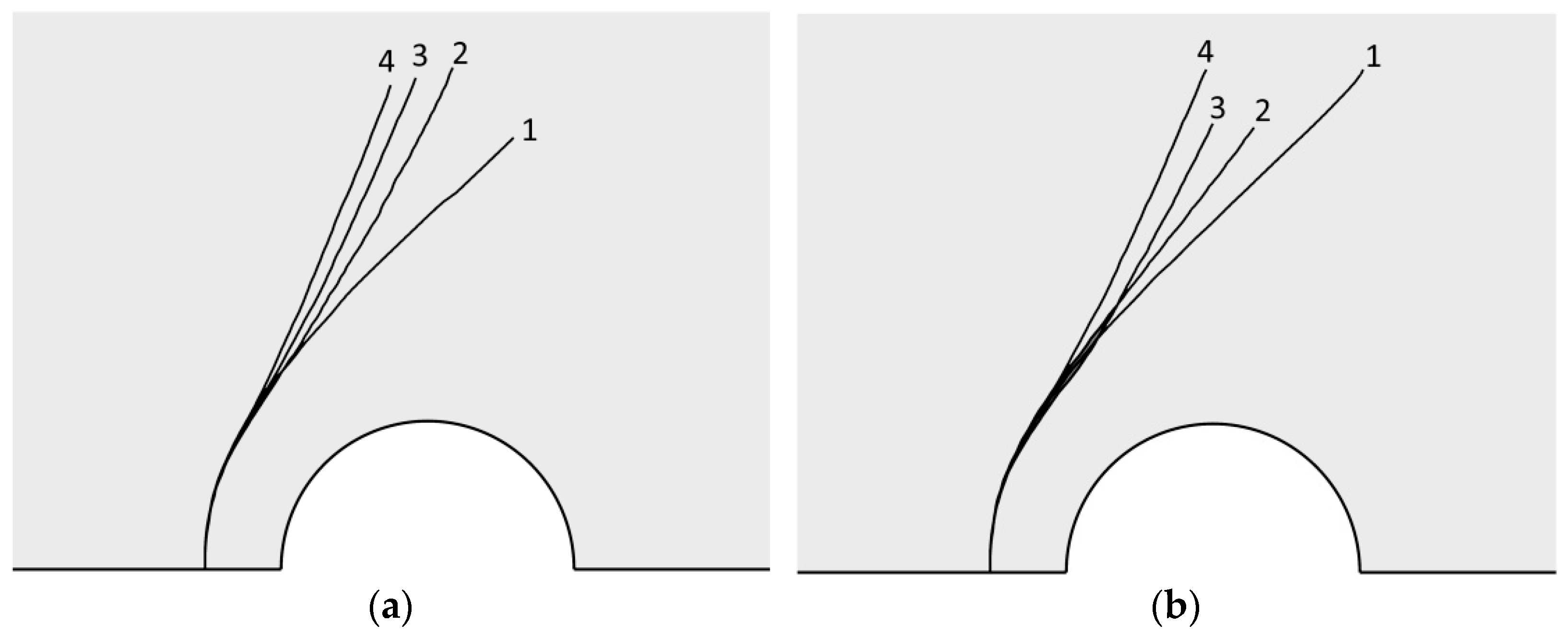
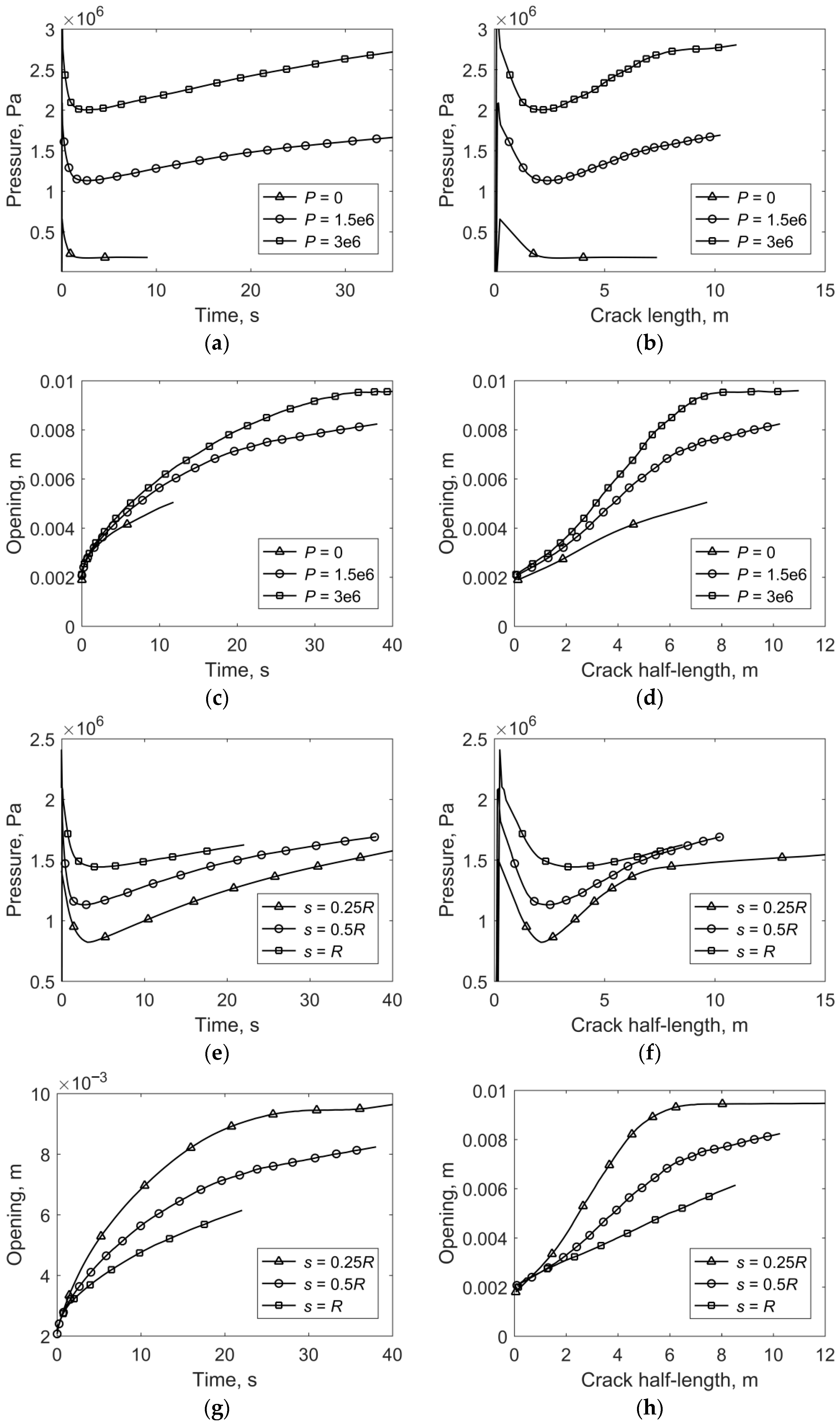
3.4. Influence of s and P on the Hydraulic Fracturing Parameters

In the following numerical experiments, we investigate the effect of the hydrostatic stress in the medium and the distance between the initial crack and the cavity on the fluid pressure and the opening of the mouth of the crack. For simplicity, here, we will consider the uncoupled problem. In the first experiment, the crack was located at a distance equal to half of the radius of the cavity (s = 0.5 R), and the hydrostatic pressure in the medium was changed. Figure 8a,b show the pressure curves that were obtained as a function of injection time and the half-length of the crack for P = 0, P = 1.5 MPa, and P = 3 MPa. The graphs show that the fracture pressure increases as the hydrostatic stress increases. At the same time, the minimum on the pressure curves becomes more pronounced (which can be seen better in Figure 8b) when plotting the pressure versus the half-length of the crack). In the absence of hydrostatic stress, the minimum pressure disappears. Figure 8c,d show the opening of the mouth of the crack. As expected, the opening of the mouth of the crack increases as the pressure of the fluid increases. If the opening of the mouth of the crack is drawn as a function of the half-length of the crack (Figure 8d), it can be seen that, for a hydrostatic stress of 3 MPa, the opening pressure changes insignificantly when a certain length is reached.
In the next experiment, the hydrostatic stress in the medium is 1.5 MPa, and the distance from the initial crack to the cavity changed and is equal to 0.25 R, 0.5 R, and 1.0 R. Figure 8e,f show the fluid pressure at the mouth of the crack. It can be seen that, when the initial crack gets closer to the cavity, the fluid pressure at the mouth for the initial stages of crack propagation decreases, and the minimum becomes more pronounced. Figure 8g,h show graphs of the opening of the mouth of the crack. Figure 8h shows that, when the initial crack is close to the cavity, the opening quickly reaches a certain value, after which it changes insignificantly. At the same time, a decrease of the distance s leads to an increase in the values of the opening of the mouth at the initial stages of the propagation of the crack.
Thus, we have shown that the value of the minimum on the pressure curve is sensitive to the stress state in the medium and the position of the initial crack. Based on these facts, in the future, we plan to develop a method for determining the stress state of a rock mass near mines. The method will consist of performing a series of hydraulic fracturing treatments near the mine in order to record the fluid pressure curves in the crack. In addition, the inverse problem of determining the stress state will be solved.
The results of the provided numerical experiments comport with the existing research. Figure 3, Figure 4, Figure 5 and Figure 6 show that, with an increase in material strength and elastic modulus and decrease in permeability, fracture trajectories are less curved, which is consistent with the conclusions in [41,50,51,52]. Additionally, in the work, the Biot coefficient characterizing the degree of problem coupling was used to study the effect of the medium’s poroelastic model on hydraulic fracturing (Figure 5a and Figure 7).
Additionally, unlike in other research [35,52,53], the problem was formulated when the initial crack is oriented parallel to the surface of the circular cavity and removed from it at a given distance, thus making it possible to observe the change in fluid pressure at the fracture and crack mouth opening during the crack’s growth. Figure 7 shows that, when taking the poroelasticity into account, it leads to fluid pressure increases in the fracture, which was observed in other research [39,51].

4. Conclusions

This article describes a study that was conducted to determine the propagation of a hydraulic fracture near a circular cavity in a poroelastic medium. Numerical method XFEM implemented in the ABAQUS software package was used for research. It was shown that the presence of a cavity affects the path of a crack. The path of a crack depends strongly on the state of the stress in the medium and the distance between the crack and the cavity. The closer the initial crack is to the cavity and the higher the stress is in the medium, the more curved the crack will become. It was shown that the values of the Biot coefficient and the permeability of the medium also affect the paths of hydraulic fractures. The crack curved less for a high value of Biot’s coefficient and low permeability. It was shown that the fluid pressure in the crack during injection has a minimum value, and this value depends on the poroelastic parameters, the stress state of the medium, and the position of the initial crack. The higher the stress is in the medium and the smaller the distance is between the initial crack and the cavity, the more pronounced the minimum becomes. It also was shown that the opening in the mouth of the crack increases both with an increase in the stress and a decrease in the distance between the crack and the cavity.
In this work, we considered the 2D problem in order to understand the main features of the development of hydraulic fractures near cavities, depending on the parameters of the model used. This simplification is clearly not always correct. Therefore, further efforts will be aimed at solving a similar 2D problem. Despite the importance of studying the process of crack propagation near the cavity in a 3D setting, few studies, to the best of our knowledge, cover this issue. One of the reasons for this is the high computational complexity of existing modeling algorithms. However, we hope that the XFEM method with its advantages remains a suitable tool for solving the problem.
We also note that, in this study, much attention is paid to the behavior of the fluid pressure in the fracture depending on the parameters and geometry of the problem, which complements the existing work in the literature. One of the reasons why this was considered in such detail is the possibility of creating a new method for determining the stress state of a rock mass by analyzing the pressure of fracturing fluid carried out near a mine working. The development of this method is the goal of future research.

Author Contributions

Conceptualization, methodology and formal analysis, A.A. and A.P.; software, validation, A.A.; investigation and writing, A.A., A.P. and S.S.; supervision, S.S. All authors have read and agreed to the published version of the manuscript.

Funding

This research was supported by the Russian Science Foundation, project number 20-17-00087.

Institutional Review Board Statement

Not applicable.

Informed Consent Statement

Not applicable.

Data Availability Statement

Not applicable.

Conflicts of Interest

The authors declare no conflict of interest.

References

  1. Yoo, H.; Park, S.; Xie, L.; Kim, K.I.; Min, K.B.; Rutqvist, J.; Rinaldi, A.P. Hydro-mechanical modeling of the first and second hydraulic stimulations in a fractured geothermal reservoir in Pohang, South Korea. Geothermics 2021, 89, 101982. [Google Scholar] [CrossRef]
  2. AbuAisha, M.; Loret, B.; Eaton, D. Enhanced Geothermal Systems (EGS): Hydraulic fracturing in a thermo-poroelastic framework. J. Pet. Sci. Eng. 2016, 146, 1179–1191. [Google Scholar] [CrossRef]
  3. Xing, Y.; Zhang, G.; Luo, T.; Jiang, Y.; Ning, S. Hydraulic fracturing in high-temperature granite characterized by acoustic emission. J. Pet. Sci. Eng. 2019, 178, 475–484. [Google Scholar] [CrossRef]
  4. Cladouhos, T.; Petty, S.; Larson, B.; Iovenitti, J.; Livesay, B.; Baria, R. Toward more efficient heat mining: A planned enhanced geothermal system demonstration project. GRC Trans. 2009, 33, 165–170. [Google Scholar]
  5. Eshiet, K.I.; Sheng, Y. Carbon dioxide injection and associated hydraulic fracturing of reservoir formations. Environ. Earth Sci. 2014, 72, 1011–1024. [Google Scholar] [CrossRef] [Green Version]
  6. Fu, P.; Settgast, R.R.; Hao, Y.; Morris, J.P.; Ryerson, F.J. The influence of hydraulic fracturing on carbon storage performance. J. Geophys. Res. Solid Earth 2017, 122, 9931–9949. [Google Scholar] [CrossRef] [Green Version]
  7. Fu, P.; Ju, X.; Huang, J.; Settgast, R.R.; Morris, J.P. THM modeling of poroelastic sustainability of hydraulic fracture in CO2 storage reservoirs. In Proceedings of the 53rd US Rock Mechanics/Geomechanics Symposium, New York, NY, USA, 23–26 June 2019; pp. 4369–4374. [Google Scholar]
  8. Schlüter, R.; Mischo, H. In-situ underground bioleaching—Novel conditioning technologies. In Proceedings of the 2015 SME Annual Meeting and Conference, Denver, CO, USA, 15–18 February 2015; pp. 299–303. [Google Scholar]
  9. Werner, A.; Haseneder, R.; Repke, J.U. Design and conception of a membrane pilot plant for the in situ treatment of bioleaching solutions. Chem. Ing. Tech. 2019, 91, 145–150. [Google Scholar] [CrossRef] [Green Version]
  10. Guo, Q.; Geehan, T.; Ovalle, A.P. Increased assurance of drill cuttings re-injection-challenges, recent advances and case studies. SPE Drill. Complet. 2007, 22, 99–105. [Google Scholar] [CrossRef]
  11. Gaurina-Međimurec, N.; Pašić, B.; Mijić, P.; Medved, I. Deep underground injection of waste from drilling activities—An overview. Minerals 2020, 10, 303. [Google Scholar] [CrossRef] [Green Version]
  12. Jeffrey, R.; Mills, K.; Zhang, X. Experience and results from using hydraulic fracturing in coal mining. In Proceedings of the 3rd International Workshop on Mine Hazards Prevention and Control, Brisbane, Australia, 19–21 November 2013; pp. 110–116. [Google Scholar]
  13. Plaksin, M.S.; Rodin, R.I. Improvement of degasification efficiency by pulsed injection of water in coal seam. In Proceedings of the IOP Conference Series: Earth and Environmental Science, Novokuznetsk, Russia, 4–7 June 2019; Volume 377, p. 012052. [Google Scholar] [CrossRef]
  14. Guanhua, N.; Hongchao, X.; Zhao, L.; Lingxun, Z.; Yunyun, N. Improving the permeability of coal seam with pulsating hydraulic fracturing technique: A case study in Changping coal mine, China. Process Saf. Environ. Prot. 2018, 117, 565–572. [Google Scholar] [CrossRef]
  15. Shilova, T.; Patutin, A.; Serdyukov, S. Sealing quality increasing of coal seam gas drainage wells by barrier screening method. In Proceedings of the International Multidisciplinary Scientific GeoConference SGEM, Albena, Bulgaria, 16–22 June 2013; Volume 1, pp. 701–708. [Google Scholar] [CrossRef]
  16. Shilova, T.; Patutin, A.; Rybalkin, L.; Serdyukov, S.; Hutornoy, V. Development of the impermeable membranes using directional hydraulic fracturing. Procedia Eng. 2017, 191, 520–524. [Google Scholar] [CrossRef]
  17. Lekontsev, Y.M.; Sazhin, P.V. Directional hydraulic fracturing in difficult caving roof control and coal degassing. J. Min. Sci. 2014, 50, 914–917. [Google Scholar] [CrossRef]
  18. Huang, B.; Wang, Y. Roof weakening of hydraulic fracturing for control of hanging roof in the face end of high gassy coal longwall mining: A Case study. Arch. Min. Sci. 2016, 61, 601–615. [Google Scholar] [CrossRef] [Green Version]
  19. Yang, J.; Liu, B.; Bian, W.; Chen, K.; Wang, H.; Cao, C. Application Cumulative Tensile Explosions for Roof Cutting in Chinese Underground Coal Mines. Arch. Min. Sci. 2021, 66, 421–435. [Google Scholar] [CrossRef]
  20. Kang, H.; Zhang, X.; Si, L.; Wu, Y.; Gao, F. In-situ stress measurements and stress distribution characteristics in underground coal mines in China. Eng. Geol. 2010, 116, 333–345. [Google Scholar] [CrossRef]
  21. Rubtsova, E.V.; Skulkin, A.A. Hydraulic fracturing stress measurement in underground salt rock mines at Upper Kama Deposit. In Proceedings of the IOP Conference Series: Earth and Environmental Science, Novosibirsk, Russia, 2–6 October 2017; Volume 134, p. 012049. [Google Scholar] [CrossRef] [Green Version]
  22. Serdyukov, S.V.; Kurlenya, M.V.; Patutin, A.V. Hydraulic fracturing for in situ stress measurement. J. Min. Sci. 2016, 52, 1031–1038. [Google Scholar] [CrossRef]
  23. Khristianovic, S.A.; Zheltov, Y.P. Formation of vertical fractures by means of highly viscous liquid. In Proceedings of the World Petroleum Congress Proceedings, Rome, Italy, 6–15 June 1955; pp. 579–586. [Google Scholar]
  24. Geertsma, J.; de Klerk, F. A rapid method of predicting width and extent of hydraulically induced fractures. J. Pet. Technol. 1969, 21, 1571–1581. [Google Scholar] [CrossRef]
  25. Perkins, T.K.; Kern, L.R. Widths of hydraulic fractures. J. Pet. Technol. 1961, 13, 937–949. [Google Scholar] [CrossRef]
  26. Nordgren, R.P. Propagation of a vertical hydraulic fracture. SPE J. 1972, 12, 306–314. [Google Scholar] [CrossRef]
  27. Zhang, X.; Jeffrey, R.G.; Thiercelin, M. Deflection and propagation of fluid-driven fractures at frictional bedding interfaces: A numerical investigation. J. Struct. Geol. 2007, 29, 396–410. [Google Scholar] [CrossRef]
  28. Wang, T.; Zhou, W.; Chen, J.; Xiao, X.; Li, Y.; Zhao, X. Simulation of hydraulic fracturing using particle flow method and application in a coal mine. Int. J. Coal Geol. 2014, 121, 1–13. [Google Scholar] [CrossRef]
  29. Olovyanny, A.G. Mathematical modeling of hydraulic fracturing in coal seams. J. Min. Sci. 2005, 41, 61–67. [Google Scholar] [CrossRef]
  30. Yan, X.; Huang, Z.; Yao, J.; Zhang, Z.; Liu, P.; Li, Y.; Fan, D. Numerical simulation of hydro-mechanical coupling in fractured vuggy porous media using the equivalent continuum model and embedded discrete fracture model. Adv. Water Resour. 2019, 126, 137–154. [Google Scholar] [CrossRef]
  31. Bubshait, A.; Jha, B. Coupled poromechanics-damage mechanics modeling of fracturing during injection in brittle rocks. Int. J. Numer. Methods Eng. 2020, 121, 256–276. [Google Scholar] [CrossRef]
  32. Yun, K.; Kim, T.J.; Jang, P.S.; Wang, Z.; Ronald, S. An improved crack tracking algorithm with self-correction ability of the crack path and its application in a continuum damage model. Int. J. Numer. Methods Eng. 2019, 117, 249–269. [Google Scholar] [CrossRef]
  33. Xia, B.; Zhang, X.; Yu, B.; Jia, J. Weakening effects of hydraulic fracture in hard roof under the influence of stress arch. Int. J. Min. Sci. Technol. 2018, 28, 951–958. [Google Scholar] [CrossRef]
  34. Cherdantsev, N.V. Approach to constructing a hydraulic fracture trajectory in a rock mass near a mine working. Mech. Solids 2020, 55, 1372–1391. [Google Scholar] [CrossRef]
  35. Liu, Z.; Lu, Q.; Sun, Y.; Tang, X.; Shao, Z.; Weng, Z. Investigation of the Influence of Natural Cavities on Hydraulic Fracturing Using Phase Field Method. Arab. J. Sci. Eng. 2019, 44, 10481–10501. [Google Scholar] [CrossRef]
  36. Chen, Z.; Li, X.; Dusseault, M.B.; Weng, L. Effect of excavation stress condition on hydraulic fracture behaviour. Eng. Fract. Mech. 2020, 226, 106871. [Google Scholar] [CrossRef]
  37. Azarov, A.V.; Serdyukov, S.V.; Patutin, A.V. Investigation of hydraulic fracture growth near a mine opening. J. Fundam. Appl. Min. Sci. 2019, 6, 26–31. [Google Scholar] [CrossRef]
  38. Zhao, H.; Xie, Y.; Zhao, L.; Liu, Z.; Li, Y.; Li, N. Simulation of mechanism of hydraulic fracture propagation in fracture-cavity reservoirs. Chem. Technol. Fuels Oils 2020, 55, 814–827. [Google Scholar] [CrossRef]
  39. Golovin, S.V.; Baykin, A.N. Influence of pore pressure on the development of a hydraulic fracture in poroelastic medium. Int. J. Rock Mech. Min. Sci. 2018, 108, 198–208. [Google Scholar] [CrossRef] [Green Version]
  40. Azarov, A.V.; Kurlenya, M.V.; Serdyukov, S.V.; Patutin, A.V. Features of hydraulic fracturing propagation near free surface in isotropic poroelastic medium. J. Min. Sci. 2019, 55, 1–8. [Google Scholar] [CrossRef]
  41. Feng, Y.; Gray, K.E. Modeling of curving hydraulic fracture propagation from a wellbore in a poroelastic medium. J. Nat. Gas Sci. Eng. 2018, 53, 83–93. [Google Scholar] [CrossRef]
  42. Wang, H.; Marongiu-Porcu, M.; Economides, M.J. Poroelastic and poroplastic modeling of hydraulic fracturing in brittle and ductile formations. SPE Prod. Oper. 2016, 31, 47–59. [Google Scholar] [CrossRef]
  43. Zeng, Q.D.; Yao, J.; Shao, J. Study of hydraulic fracturing in an anisotropic poroelastic medium via a hybrid EDFM-XFEM approach. Comput. Geotech. 2019, 105, 51–68. [Google Scholar] [CrossRef]
  44. Bruno, M.S.; Nakagawa, F.M. Pore pressure influence on tensile fracture propagation in sedimentary rock. Int. J. Rock Mech. Min. Sci. Geomech. Abstr. 1991, 28, 261–273. [Google Scholar] [CrossRef]
  45. Wang, S.Y.; Sloan, S.W.; Fityus, S.G.; Griffiths, D.V.; Tang, C.A. Numerical modeling of pore pressure influence on fracture evolution in brittle heterogeneous rocks. Rock Mech. Rock Eng. 2013, 46, 1165–1182. [Google Scholar] [CrossRef]
  46. He, B.; Zhuang, X. Modeling hydraulic cracks and inclusion interaction using XFEM. Undergr. Space 2018, 3, 218–228. [Google Scholar] [CrossRef]
  47. Yang, T.; Zhu, W.; Yu, Q.; Liu, H. The role of pore pressure during hydraulic fracturing and implications for groundwater outbursts in mining and tunnelling. Hydrogeol. J. 2011, 19, 995–1008. [Google Scholar] [CrossRef]
  48. Ortiz, M.; Pandolfi, A. Finite-deformation irreversible cohesive elements for three-dimensional crack-propagation analysis. Int. J. Numer. Methods Eng. 1999, 44, 1267–1282. [Google Scholar] [CrossRef]
  49. Irwin, G.R. Analysis of stresses and strains near the end of a crack traversing a plate. J. Appl. Mech. 1957, 24, 361–364. [Google Scholar] [CrossRef]
  50. Martynyuk, P.A.; Sher, E.N. Development of a crack close to a circular opening with an external field of compressive stresses. J. Min. Sci. 1996, 32, 453–463. [Google Scholar] [CrossRef]
  51. Cheng, W.; Lu, C.; Zhou, Z. Modeling of borehole hydraulic fracture initiation and propagation with pre-existing cracks using the displacement discontinuity method. Geotech. Geol. Eng. 2020, 38, 2903–2912. [Google Scholar] [CrossRef]
  52. Shi, F.; Wang, D.; Chen, X. A numerical study on the propagation mechanisms of hydraulic fractures in fracture-cavity carbonate reservoirs. CMES 2021, 127, 575–598. [Google Scholar] [CrossRef]
  53. Cheng, L.; Luo, Z.; Yu, Y.; Zhao, L.; Zhou, C. Study on the interaction mechanism between hydraulic fracture and natural karst cave with the extended finite element method. Eng. Fract. Mech. 2019, 222, 106680. [Google Scholar] [CrossRef]
Figure 1. (a) Dependence of tensile stress, σ, in the material on deformations u; (b) the fracture variable function D(u): 1—exponential, 2—linear damage evolution laws.
Applsci 11 11004 g001
Figure 2. (a) 2D area containing circular cavity and initial crack; (b) Discretization of the model used for numerical experiments.
Applsci 11 11004 g002
Figure 3. Path of hydraulic fractures at different positions of the initial crack and different hydrostatic stresses, P. Curve numbers: 1—P = 0 MPa; 2—P = 1.5 MPa; 3—P = 6 MPa.
Applsci 11 11004 g003
Figure 4. Crack path at hydrostatic stress P = 1.5 MPa: (a) various values of the critical stress σc (1—σc = 7.5 MPa; 2—σc = 0.75 MPa; 3—σc = 0.075 MPa); (b) various values of the elastic modulus, E (1—E = 30 GPa; 2—E = 3 GPa; 3—E = 0.3 GPa).
Applsci 11 11004 g004
Figure 5. Path of a crack near a cavity: (a) hydrostatic compression of the medium is 1.5 MPa, permeability k = 1 μm2, and the different numbers indicate the curves obtained for different values of the Biot coefficients: 1—α = 0; 2—α = 0.5; 3—α = 0.75; 4—α = 0.9; (b) hydrostatic compression of the medium is 1.5 MPa, the Biot coefficients, α, is 0.75, and different numbers indicate the curves obtained for different values of the permeability: 1—k = 105 μm2; 2—k = 1000 μm2; 3—k = 100 μm2; 4—k = 1 μm2.
Applsci 11 11004 g005
Figure 6. Results of modeling the hydraulic fracture propagation for an uncoupled (curves 1) and a coupled (curves 2) problem at various hydrostatic stresses: (a) hydrostatic stress is 0.75 MPa; (b) hydrostatic stress is 3 MPa.
Applsci 11 11004 g006
Figure 7. (a) The direction of crack propagation, β, as function of the angle, φ, between the horizontal line and the segment that connects the center of the cavity and the tip of the crack; (b) image of angles β and φ; (c,d) pressure on the mouth of the crack as a function of injection time and the half-length of the crack for different values of α; (e,f) opening of the mouth of the crack as a function of injection time and the half-length of the crack for different values of α; (a,cf) were obtained for a hydrostatic stress in the medium equal to 1.5 MPa and an initial crack located at the distance of s = 0.5 R from the cavity (half of the radius of the cavity).
Applsci 11 11004 g007
Figure 8. (a,b) Fluid pressure at the mouth of the crack as a function of injection time and fracture half-length for s = 0.5 R and different hydrostatic stresses, P; (c,d) the crack mouth opening as a function of injection time and crack half-length for s = 0.5 R and different hydrostatic stress, P; (e,f) the fluid pressure at the mouth of the crack as a function of injection time and fracture half-length for P = 1.5 MPa and different distance, s; (g,h) the opening of the mouth of the crack as a function of injection time and the half-length of the crack for P = 1.5 MPa and different distance, s.
Applsci 11 11004 g008
Publisher’s Note: MDPI stays neutral with regard to jurisdictional claims in published maps and institutional affiliations.

