Article

Control of an Omnidirectional UAV for Transportation and Manipulation Tasks

by
Michelangelo Nigro
*,
Francesco Pierri
and
Fabrizio Caccavale
School of Engineering, University of Basilicata, Via dell’Ateneo Lucano 10, 85100 Potenza, Italy
*
Author to whom correspondence should be addressed.
Appl. Sci. 2021, 11(22), 10991; https://doi.org/10.3390/app112210991
Submission received: 27 September 2021 / Revised: 8 November 2021 / Accepted: 17 November 2021 / Published: 19 November 2021
(This article belongs to the Special Issue Advances in Aerial, Space, and Underwater Robotics)

Abstract

:
This paper presents a motion control scheme for a new concept of omnidirectional aerial vehicle for transportation and manipulation tasks. The considered aerial platform is a novel quadrotor with the capability of providing multi-directional thrust by adding an actuated gimbal mechanism in charge of modifying the orientation of the frame on which the four rotors are mounted. The above mechanical design, differently from other omnidirectional unmanned aerial vehicles (UAVs) with tilted propellers, avoids internal forces and energy dissipation due to non-parallel propellers’ axes. The proposed motion controller is based on a hierarchical two-loop scheme. The external loop computes the force to be applied to the vehicle and the reference values for the additional joints, while the inner loop computes the joint torques and the moment to be applied to the multirotor. In order to make the system robust with respect to the external loads, a compensation of contact forces is introduced by exploiting the estimate provided by a momentum based observer. The stability of the motion control scheme is proven via Lyapunov arguments. Finally, two simulation case studies prove the capability of the omnidirectional UAV platform to track a 6-DoFs trajectory both in free motion and during a task involving grasping and transportation of an unknown object.

1. Introduction

In recent years, the use of aerial robotic platforms, due to their nearly unlimited motion space, has become popular in many applications scenarios, e.g., inspection and maintenance services [1], data collection and exploration operations [2], and precision agriculture [3]. More and more frequently, aerial robots are involved in tasks requiring both autonomous flight and physical interaction capabilities, such as assembly of structures in remote environments, object grasping [4], and payload transportation [5,6].
The most popular configuration of vertical take off and landing (VTOL) unmanned aerial vehicle (UAV) is that of a multi-rotor vehicle, i.e., an aerial vehicle equipped with four or more coplanar propellers, which offers the best trade-off between mobility, simplicity, and cost. The main drawback of classical multi-rotor vehicles is that they are underactuated systems, since thrusts generated by propellers are directed along parallel axes, orthogonal to the plane of the propellers [7]. Therefore, in order to change its position and/or counteract external disturbances, rotation of vehicle’s body is required: thus, only four degrees of freedom (DOFs) are left to execute the task assigned to the UAV. This limitation may become severe in some applications that might benefit from availability of all six DOFs, e.g., manipulation tasks involving contact with the environment [8], and/or limit the disturbance counteraction capabilities of the system. To overcome this problem, in recent years, platforms with multi-directional thrust have been designed. One of the most common approaches is based on the use of tilted propellers, e.g., as in [9,10]. The overactuated platforms require additional motors for tilting the propellers, and this has the negative effect of increasing the system weight and the complexity of the control for handling both vertical and lateral air flows. Such a problem can be overcame by adopting hexarotors with tilted propellers, e.g., as in [11], where each rotor is mounted in a fixed configuration rotated about two axes. More efficient solutions are proposed in [12,13]. More in detail, in [12], an additional motor is added in order to tilt all propellers at the same time, in such a way as to reduce the energy consumption and the total mass, allowing to drive the platform from a configuration energetically efficient, but underactuated to a fully actuated but less efficient one. In [13], an hexarotor with independently tiltable rotors is designed; the tilting angle of the rotors is computed online via a suitable control allocation scheme. This platform by exploiting its bi-directional thrusters can apply forces in any direction, while for the other platforms using uni-directional thrusters, the forces are usually limited in the upper hemisphere. An interesting analysis conducted in [14] proved that, for uni-directional thrusters, the minimum number of rotors in order to achieve omnidirectional forces is seven. Such analysis leads to the platform in [15], which is equipped with seven propellers, whose tilting angles are computed according to the optimization procedure in [14] and guarantee the omnidirectional property of the platform, while enforcing equal sharing of the desired forces between the propellers.
The previous solutions, do not avoid internal wrenches caused by counteracting actuators and require redundant control inputs. In order to overcome this problem, in [16], a quadrotor vehicle is designed, with the tilting angle of the propellers simultaneously controlled by two additional actuators via a parallelogram mechanism. In this way, only six inputs are adopted to control six degrees of freedom (DOFs), and the thrust generated by all propellers is always aligned along the same direction, thus avoiding energy dissipation due to internal wrench. A similar configuration has been proposed in [17], where a new concept of omnidirectional aerial vehicle, named ODQuad, is designed in particular for transportation and manipulation tasks. The ODQuad is a quadrotor with the capability of providing multi-directional thrusts by rotating the frame on which the four rotors are mounted through two actuated rotational joints realizing a two-axis (roll and pitch) gimbal mechanism.
For classical underactuated multi-rotors, several controllers have been proposed, mostly based on linear approaches [18,19], often requiring model linearization about a set of equilibrium conditions. Such controllers allow to achieve satisfactory performance near the design conditions and in hovering conditions, but performance degradation is usually observed when the aircraft moves away from these conditions. To overcome these drawbacks, nonlinear controllers have been designed, including model predictive control [20], backstepping and sliding mode techniques [21,22], adaptive control [23], impedance control [24,25], and geometric control [26]. More recently, data-based control approaches have been designed for achieving high-performance trajectory tracking with UAVs: in detail, in [27], an innovative iterative learning control algorithm is proposed based on an estimation of repetitive disturbances to improve the learning performance.
Regarding the omnidirectional aerial platforms, the most common control approach is feedback linearization, aimed at decoupling the six DOFs that can be controlled separately. Such approaches are model-based; the nonlinear dynamical effects are compensated, and then the thrust is derived from the inversion of the control allocation matrix. Some examples of feedback linearization approaches can be found in [11,16,28]. One of the main issues occurring in feedback linearization is that the actuator saturation can destabilize the system. Solutions to this drawback have been proposed. In [29], the six inputs of a coplanar hexarotor are mapped in a four dimensional task output (i.e., the total thrust and the three moment components) via a weighted pseudoinverse. In [30], for constant position and attitude references, input saturation is avoided by resorting to an approach based on the explicit reference governor, which provides constraint handling capabilities by suitably manipulating the derivative of the applied reference [31]. In [32], a general geometric tracking controller for time-varying references is proposed, which also takes into account the bounds on the lateral control force.
The aim of this paper is to present a novel motion control scheme for the ODQuad vehicle [17] and to test it both in free-space motion and in the presence of external disturbances, such as the contact with an object during a task of manipulation and transportation. More in detail, a model-based feedback linearization controller is proposed that computes the reference signals using a hierarchical two-loop scheme: the outer loop is a position controller aimed at computing the global thrust force and the reference values for the pitch and roll angles of the gimbal mechanism; then, in the inner loop, an attitude and gimbal controller, on the basis of these references, computes the moments acting on the quadrotor and the joint torques. A preliminary version of such a scheme has been introduced in [17]; here, two contribution are added: (i) the stability analysis of the system, based on Lyapunov arguments; and (ii) the extension to the case of contact with an object with the compensation of the interaction wrench performed via an online estimator. Finally, in order to prove the effectiveness of the approach, simulation case studies have been developed, in which the controller is tested in a non-ideal context by considering model uncertainties and sensor noise.
It is worth pointing out that, although the ODQuad is conceived to perform tasks both in free space and involving interaction with the environment, the aim of this paper is to design and validate the first building block of the whole control architecture, namely the motion control. Notice that the sole motion controller presented in this paper cannot tackle interaction with the environment and needs to be integrated in an interaction control scheme (e.g., impedance control, hybrid force/position control).
The paper is organized as follows. In Section 2, the mechanical design of the ODQuad is reported and detailed; Section 3 reports both the kinematic and dynamic models, which will be exploited by the control law. The two-loop control scheme is presented in Section 4, while its stability properties are analyzed in Section 5. Section 6 reports the formulation of the control laws in the presence of contact with an object during transportation or manipulation tasks. Section 7 reports the simulation results and finally some conclusions are drawn.

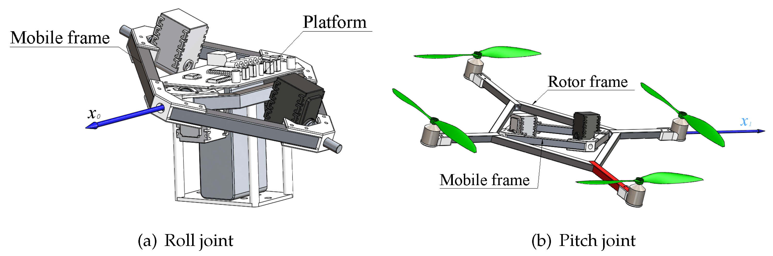
2. ODQuad: A Novel Omnidirectional Quadrotor

The ODQuad vehicle, firstly introduced in [17], is an omnidirectional quadrotor composed of the following three components:
  • A platform, hosting computing hardware, electronics, batteries, and sensors;
  • A rotor frame that supports the propellers;
  • A mobile frame that connects the platform and the rotor frames with the roll and pitch rotational joints.
The first rotational joint connects the platform to the mobile frame (roll joint, see Figure 1a), while the other joint (pitch joint, see Figure 1b) connects the mobile frame to the rotor frame. Both the joints are actuated by servo motors equipped with angular position sensors.
Differently from the common multi-rotor design, the ODQuad is able to change the orientation of the total thrust with respect to the horizontal plane without modifying the platform orientation by moving the roll and pitch joints. This allows one to have all the six DOFs available for the platform motion. In the current design, due to mechanical constraints, the roll and pitch joints can be moved in a range from −25 deg to 25 deg.
The mechanical limits imposed to the roll and pitch joints limit the solid angle that the total trust could span. Thus, according to the taxonomy introduced in [33], it could be more appropriate to refer to the ODQuad as a platform with multi-directional thrust instead of an omnidirectional platform, but in practical applications and in the absence of acrobatic maneuvers, the spanned wrench space is enough to guarantee the fulfillment of the most common tasks.
In order to derive the ODQuad’s kinematics, let us define the following coordinate frames:
  • The inertial coordinate frame, Σ { O , x , y , z }
  • The coordinate frame Σ 0 { O 0 , x 0 , y 0 , z 0 } , attached to the platform in such a way that the axis x 0 coincides with the axis of the roll joint
  • The coordinate frame Σ 1 { O 1 , x 1 , y 1 , z 1 } , attached to the mobile frame in such a way that the axis x 1 coincides with the axis of the pitch joint
  • The coordinate frame Σ 2 { O 2 , x 2 , y 2 , z 2 } , attached to the rotor frame in such a way that the axis x 2 coincides with x 1 .
The reference frames Σ 0 , Σ 1 , and Σ 2 have the same origin, i.e., O 0 O 1 O 2 , while the relative orientation is expressed by the following rotation matrices:
R 1 0 ( α ) = 0 1 0 c α 0 s α s α 0 c α , R 2 1 ( β ) = 1 0 0 0 c β s β 0 s β c β ,
where α is the pitch angle, β is the roll angle, c α = cos α , s α = sin α , c β = cos β , s β = sin β , and R i j denote the rotation matrix expressing the orientation of Σ i with respect to Σ j .

3. Modeling

The dynamic model of the system has been derived in [17] according the Euler–Lagrange formulation, using the following generalized coordinates:
q = p 0 T ϕ 0 T δ T T I R 8 ,
where p 0 I R 3 is the position of O 0 with respect to the inertial frame, ϕ 0 = ϕ θ ψ T I R 3 is the vector of roll-pitch-yaw angles, which express the platform orientation with respect to the inertial frame, and δ = α β T I R 2 collects the roll-pitch joint positions.

3.1. Kinematics

To properly derive the dynamic model of the system, the position and velocities of the center of mass (CoM) of the ODQuad components, i.e., platform, mobile frame, and propeller’s frame, have to be computed. To this aim, let us define three new reference frames: Σ C 0 , Σ C 1 and Σ C 2 , attached, respectively, to the CoM of the platform ( C 0 ), mobile frame ( C 1 ) and propeller’s frame ( C 2 ). The linear and angular velocities of Σ C * , ( * = 0 , 1 , 2 ) , can be expressed in terms of the generalized coordinates as
p ˙ C 0 = J P 0 ( q ) q ˙ , ω C 0 = J O 0 ( q ) q ˙ , p ˙ C 1 = J P 1 ( q ) q ˙ , ω C 1 = J O 1 ( q ) q ˙ , p ˙ C 2 = J P 2 ( q ) q ˙ , ω C 2 = J O 2 ( q ) q ˙ ,
where the Jacobian matrices J P * I R 3 × 8 and J O * I R 3 × 8 , ( * = 0 , 1 , 2 ) are given by [17]
J P 0 = I 3 S ( r 0 , C 0 ) T ( ϕ 0 ) 0 3 0 3 , J O 0 = O 3 T ( ϕ 0 ) 0 3 0 3 , J P 1 = I 3 S ( r 1 , C 1 ) T ( ϕ 0 ) S ( r 1 , C 1 ) x 0 0 3 , J O 1 = O 3 T ( ϕ 0 ) x 0 0 3 , J P 2 = I 3 S ( r 2 , C 2 ) T ( ϕ 0 ) S ( r 2 , C 2 ) x 0 S ( r 2 , C 2 ) x 1 , J O 2 = O 3 T ( ϕ 0 ) x 0 x 1 ,
the vector r * , C * denotes the position of C * with respect to O * , ( * = 0 , 1 , 2 ) , expressed in the inertial frame; T ( ϕ 0 ) is the matrix relating the derivative of the roll-pitch-yaw angles, ϕ ˙ 0 , to the angular velocity, ω 0 [34]; I 3 and O 3 are the ( 3 × 3 ) identity and null matrices, respectively; 0 3 is the ( 3 × 1 ) null vector; while x * is the first column of R * ( * = 0 , 1 ) , which is the rotation matrix expressing the orientation of the frame Σ * with respect to the inertial frame.

3.2. Dynamics

The dynamic model can be written in compact form as
M ( q ) q ¨ + C ( q , q ˙ ) q ˙ + g ( q ) = η ,
where M ( q ) I R 8 × 8 is the symmetric and positive definite inertia matrix
M ( q ) = I = 0 2 m i J P i T ( q ) J P i ( q ) + J O i T ( q ) M i J O i ( q ) ,
m i ( i = 0 , 1 , 2 ) is the mass of the ith component (platform, rotor frame, and mobile frame) of the ODQuad, M i is its inertia tensor expressed in the inertial frame. The matrix C ( q , q ˙ ) I R 8 × 8 collects the Coriolis and centrifugal terms
C ( q , q ˙ ) q ˙ = M ˙ ( q ) q ˙ q 1 2 q ˙ T M ( q ) q ˙ T .
The vector g ( q ) I R 8 contains the generalized gravitational forces
g ( q ) = i = 0 2 m i g ¯ T J P i ( q ) ,
with g ¯ T = [ 0 0 9.81 ] T .
The vector η collects the external generalized forces acting as inputs, i.e.,
η = f 0 μ 0 τ δ ,
where f 0 and μ 0 are the force and moment, respectively, acting on the platform, and τ δ I R 2 are the torques acting on the roll-pitch joint. The force f 0 depends on the four propellers’ thrusts, σ i ( i = 1 , , 4 ), that are directed along the z 2 axis. Therefore, the total force acting on the platform, expressed in Σ 2 , has the following expression, f 2 = [ 0 0 f z ] T . The input f 0 can be derived from f 2 , expressed in the inertial frame
f 0 = R 2 f 2 ,
where R 2 represents the orientation of the frame Σ 2 with respect to the inertial one. Analogously, the moment μ 0 can be written as
μ 0 = R 2 μ 2 + S ( r 2 , C 2 2 ) f 2 ,
where μ 2 is the moment generated by the propellers expressed in frame Σ 2 . In turn, f 2 and μ 2 can be expressed as [7]
f z μ 2 = 1 1 1 1 l 0 l 0 0 l 0 l c c c c σ 1 σ 2 σ 3 σ 4 = N σ ,
where l > 0 is the distance of each rotor from O 2 , c = γ d / γ t , while γ d and γ t are the drag and thrust coefficients, respectively.
The torque vector τ δ is given by the sum of the torques generated by the joint actuators, τ c , and the effect of the thrusts on the joints
τ δ = τ c + J 2 T h 2 ,
where
J 2 = J P 2 J O 2 , h 2 = R 2 f 2 R 2 μ 2 .
For control design purposes, the matrices in (5) can be written as block matrices
M = M p p M p ϕ M p δ M p ϕ T M ϕ ϕ M ϕ δ M p δ T M ϕ δ T M δ δ ,
where M p p I R 3 × 3 , M p ϕ I R 3 × 3 , M p δ I R 3 × 2 , M ϕ ϕ I R 3 × 3 , M ϕ δ I R 3 × 2 and M δ δ I R 2 × 2 , and
C = C p C ϕ C δ , g = g p g ϕ g δ ,
where C p I R 3 × 8 , C ϕ I R 3 × 8 , C δ I R 2 × 8 , g p I R 3 , g ϕ I R 3 , g δ I R 2 .
The block decomposition allows us to rearrange the dynamic model (5) as
M p p p ¨ 0 + M p ϕ ϕ ¨ 0 + M p δ δ ¨ + C p p ˙ 0 + g p = f 0
M p ϕ T p ¨ 0 + M ϕ ϕ ϕ ¨ 0 + M ϕ δ δ ¨ + C ϕ ϕ ˙ 0 + g ϕ = μ 0
M p δ T p ¨ 0 + M ϕ δ T ϕ ¨ 0 + M δ δ δ ¨ + C δ δ ˙ + g δ = τ δ ,
where the arguments of the matrices have been dropped for compactness.

4. Motion Control

The proposed motion control is a two-loop model-based scheme inherited from [35]: the outer loop performs the position controller, while the inner loop controls the platform orientation and the roll-pitch joint position. A sketch of the control block scheme is reported in Figure 2. More in detail, the position controller is in charge of computing the force, f 0 , to be exerted to the vehicle’s platform in order to achieve the desired vehicle’s position trajectory and the reference angles, α d e s and β d e s , for the roll-pitch joints. The reference angles are fed to the inner loop, which computes, on the basis of the platform’s desired orientation, both the torques τ c for the roll-pitch joint actuators and the moment μ 0 .
The control purpose is the tracking of an off-line planned desired trajectory for the platform (i.e., for the coordinate frame Σ 0 ) defined by the vectors p 0 , d ( t ) and ϕ 0 , d ( t ) , their corresponding velocities, p ˙ 0 , d ( t ) , ϕ ˙ 0 , d ( t ) , and accelerations, p ¨ 0 , d ( t ) , ϕ ¨ 0 , d ( t ) .
Remark 1.
It is worth noticing that the ODQuad, differently from usual underactuated quadrotors, allows us to control both position and orientation, provided that the assigned orientation, ϕ 0 , d , can be reached without violation of the limit of roll and pitch angles of the gimbal mechanism (i.e., α , β [ 25 , + 25 ] deg for the current design).

4.1. Outer Loop: Position Controller

The outer control loop is designed to track the assigned position by introducing a virtual control vector aimed at linearizing the position dynamics. In order to design the control law, it is worth rewriting Equation (14) as
M p p p ¨ 0 + M p ϕ ϕ ¨ 0 + C p p ˙ 0 + g p = f 0 ,
where it has been assumed M p δ O 3 × 2 , with O 3 × 2 the ( 3 × 2 ) null matrix. This assumption allows to decouple the inner and the outer loop. Hence, on the basis of (17), the force to be exerted to the platform is computed as
f 0 = M p p γ p + M p ϕ γ ϕ + C p p ˙ 0 + g p ,
where the auxiliary inputs γ * ( * = p , ϕ ) are defined as
γ p = p ¨ 0 , d + K D , p p ˙ 0 , d p ˙ 0 + K P , p p 0 , d p 0 + K I , p 0 t p 0 , d p 0 d ρ ,
γ ϕ = ϕ ¨ 0 , d + K D , ϕ ϕ ˙ 0 , d ϕ ˙ 0 + K P , ϕ ϕ 0 , d ϕ 0 + K I , ϕ 0 t ϕ 0 , d ϕ 0 d ρ ,
and K D , * , K P , * , K I , * ( * = p , ϕ ) are symmetric and positive definite gain matrices.
Remark 2.
The position control law is designed on the basis of (17) in lieu of (14), because (14) depends on δ , and thus computing f 0 would have required the reference values for δ not available at this stage.
Once the force f 0 is determined, it is possible to compute the reference values for the roll-pitch angles by exploiting (10) and the expression of R 1 0 and R 2 1 . More in detail, let us express f 0 in the frame Σ 0 , i.e.,
f 0 0 = R 0 T f 0 .
Then, in view of (10), it is
f 0 0 = R 2 0 f 2 = R 1 0 R 2 1 f 2 .
By considering (1), the following relation can be derived
f 0 , x 0 f 0 , y 0 f 0 , z 0 = 0 c β s β c α s α s β c β s α s α c α s β c α c β 0 0 f z .
Therefore, the desired values of the joints angles and the total thrust to be provided by the propellers are given by
f z = f 0 0 = f 0 ,
α d e s = arctan f 0 , y 0 f 0 , z 0 ,
β d e s = arcsin f 0 , x 0 f 0 0 .
The desired velocity and acceleration of the roll-pitch joints can be derived by numerical differentiation; in practice, since α d e s and β d e s are affected by noise, it is recommended to use suitable robust-to-noise filters. An effective approach is detailed in [35], where the time-varying filter proposed in [36] is adopted in order to compute both the first and second time-derivatives of the reference values.
Remark 3.
In view of (23), it could be noted that (25) and (26) are not well defined if
  • f 0 vanishes: it can happen only if f z = 0 , namely in the presence of a null total thrust;
  • α = ± 90 deg or β = ± 90 deg. It cannot happen since both α and β are mechanically limited to [ 25 + 25 ] deg.
The assumption of total thrust always being non-null is a reasonable assumption for vehicles not involved in acrobatic maneuvers.

4.2. Inner Loop: Attitude and Roll-Pitch Controller

Once the reference values for roll-pitch angles, δ d = [ α d e s , β d e s ] T , and their derivatives, δ ˙ d and δ ¨ d , have been determined, the auxiliary input γ δ is computed as
γ δ = δ ¨ d + K D , δ δ ˙ d δ ˙ + K P , δ δ d δ + K I , δ 0 t δ d δ d ρ ,
where K D , δ , K P , δ and K I , δ are symmetric and positive definite gain matrices.
Therefore, the moment to be applied to the platform and the joint torques can be computed similarly to (18)
μ 0 = M p ϕ T γ p + M ϕ ϕ γ ϕ + M ϕ δ γ δ + C ϕ ϕ ˙ 0 + g ϕ
τ c = M p δ T γ p + M ϕ δ T γ ϕ + M δ δ γ δ + C δ δ ˙ + g δ J 2 T h 2 .
In view of (11), the commanded total moment to be provided by the four propellers, μ 2 , can be computed as
μ 2 = R 2 T μ 0 , c S ( r 2 , C 2 2 ) f 2 .
Finally, the rotor thrusts can be computed via (12) as
σ = N 1 f z μ 2 .

5. Stability Analysis

By folding the control inputs (18), (28), and (29) into the ODQuad dynamics (14)–(16), the following set of equations can be written
M p p ( p ¨ 0 γ p ) + M p ϕ ( ϕ ¨ 0 γ ϕ ) + M p δ δ ¨ = 0 3
M p ϕ T ( p ¨ 0 γ p ) + M ϕ ϕ ( ϕ ¨ 0 γ ϕ ) + M ϕ δ ( δ ¨ γ δ ) = 0 3
M p δ T ( p ¨ 0 γ p ) + M ϕ δ T ( ϕ ¨ 0 γ ϕ ) + M δ δ ( δ ¨ γ δ ) = 0 2 ,
where 0 2 is the ( 2 × 1 ) vector of zeros. By adding and subtracting M p δ γ δ , (32) can be rearranged in the form
M p p ( p ¨ 0 γ p ) + M p ϕ ( ϕ ¨ 0 γ ϕ ) + M p δ ( δ ¨ γ δ ) + M p δ γ δ = 0 3 .
By defining the vector γ and the block matrix M ˜ as
γ = γ p γ ϕ γ δ I R 8 , M ˜ = O 3 O 3 M p δ O 3 O 3 O 3 × 2 O 2 × 3 O 2 × 3 O 2 I R 8 × 8 ,
where O 2 and O 2 × 3 are, respectively, the ( 2 × 2 ) and ( 2 × 3 ) null matrices, Equations (33)–(35) can be rewritten in the following compact form:
M ( q ¨ γ ) + M ˜ γ = 0 8 ,
where 0 8 is the (8 × 1) vector of zeros. By exploiting Equations (19), (20) and (27), the following error dynamics is obtained:
e ¨ + K D e ˙ + K p e + K I e + M 1 M ˜ γ = 0 8 ,
where e = q d q , with q d = [ p 0 , d T , ϕ 0 , d T , δ d T ] T , and the matrices K 🟉 ( 🟉 = { I , P , D } ) are
K 🟉 = blkdiag K 🟉 , p , K 🟉 , ϕ , K 🟉 , δ .
Define the state vector z = z 1 T , z 2 T , z 3 T T = e T , e T , e ˙ T T and rewrite (37) in the state space form as
z ˙ 1 = z 2 z ˙ 2 = z 3 z ˙ 3 = ( K D z 3 + K p z 2 + K I z 1 ) M 1 M ˜ γ ,
which can be rewritten as
z ˙ = O 8 I 8 O 8 O 8 O 8 I 8 K I K P K D z + 0 8 0 8 M 1 M ˜ γ = K z + γ ˜ ,
where I 8 and O 8 are the ( 8 × 8 ) identity and null matrices, respectively. In other words, the system (39) can be seen as a nominal linear system ( z ˙ = K z ) with a perturbation term γ ˜ . Since matrix K is in block companion form and can be proven to be Hurwitz [37], the nominal system is exponentially stable.
As for the perturbation term, the following property of the inertia matrix can be exploited [34,38]:
Property 1.
M is symmetric and positive definite; therefore, if λ m i n · ( λ m a x · ) denotes the minimum (maximum) eigenvalue, it is
0 < λ m i n ( M ) I 8 M ( q ) λ m a x ( M ) I 8 .
Thus, based on Property 1, the following holds:
λ m a x 1 ( M ) < M 1 < λ m i n 1 ( M ) .
Regarding matrix M ˜ , it is worth considering the explicit expression of its sole non-null block (6), i.e.,
M p δ = m 1 S ( r 1 , C 1 ) + m 2 S ( r 2 , C 2 ) x 0 , m 2 S ( r 2 , C 2 ) x 1 ,
where x 0 and x 1 are unit vectors and all the other elements are constant and depend on the system’s geometrical and inertial properties. Thus, its norm is constant
M ˜ = M p δ = Λ .
Finally, the term γ can be written in the explicit form as
γ = q ¨ d + K D e ˙ + K P e + K I e .
The following assumption on the planned trajectory is made:
Assumption 1.
The planned acceleration q ¨ d is bounded t T , i.e., q ¨ d ( t ) q ¯ ¨ .
Therefore, the non-null block of the perturbation term can be rewritten as sum of two terms
γ ˜ 3 = M 1 M ˜ q ¨ d + M 1 M ˜ K D e ˙ + K P e + K I e .
The first term, in view of (41), (43) and of Assumption 1, is norm-bounded t
M 1 M ˜ q ¨ d 1 λ m i n ( M ) Λ q ¯ ¨ .
The second term in (44) is a vanishing perturbation (in the sense of [39]), since the following chain of inequalities holds:
M 1 M ˜ K D e ˙ + K P e + K I e 1 λ m i n ( M ) Λ K D e ˙ + K p e + K I e 1 λ m i n ( M ) Λ k M z ,
where k M = max { K P , K D , K I } .
Thus, by recurring to the theory of perturbed systems [39], the effects of the two perturbation terms can be summarized as follows:
  • by virtue of Lemma 9.1 in [39], the origin of the system (39), under the vanishing perturbation is an exponentially stable equilibrium;
  • by virtue of Lemma 9.2 in [39], the origin of the system (39), under the non-vanishing bounded perturbation is uniformly bounded.
By exploiting the linearity of the nominal system (39), it can be stated that, under Assumption 1, the error z is uniformly bounded. Moreover, if the planned acceleration vanishes after a time instant t f T , the error converges to zero exponentially.

6. Interaction Wrench Compensation

In tasks involving contact with the environment, e.g., manipulation or cooperative transportation, the capability of exerting both forces and moments without modifying the orientation of the load make the omnidirectional platforms preferable with respect to standard multirotors [8,40].
Moreover, even in simple transportation tasks, it is of the utmost importance to react to external disturbances due to contact with the object by compensating the wrench exerted by the object. Namely, an estimation of the wrench exerted by the object on the vehicle is fed back to the controller as an additional term in (18), (28), and (29). In fact, in the presence of contact with an object, the dynamics (5) of the ODQuad becomes
M ( q ) q ¨ + C ( q , q ˙ ) q ˙ + g ( q ) = η + J C T h C ,
where J C is the Jacobian matrix that relates the velocity of the contact point to the velocity of the generalized coordinates q, and h C is the wrench exerted by the object on the contact point of the ODQuad. Given an estimate, h ^ C , of h C , the control outputs (18), (28), and (29) become
f 0 = M p p γ p + M p ϕ γ ϕ + C p p ˙ 0 + g p J C , f T h ^ C , μ 0 = M p ϕ T γ p + M ϕ ϕ γ ϕ + M ϕ δ γ δ + C ϕ ϕ ˙ 0 + g ϕ J C , μ T h ^ C τ c = M p δ T γ p + M ϕ δ T γ ϕ + M δ δ γ δ + C δ δ ˙ + g δ J 2 T h 2 J C , τ T h ^ C ,
where J C , f , J C , μ , and J C , τ are obtained from J C by selecting, respectively, the first three columns, the forth to sixth columns, and the last two columns.

Wrench Estimation

In order to measure the wrench exerted by the object on the ODQuad, a force/torque sensor could be mounted on the contact point robot-object [6]. This is usually capable to provide a reliable measure, but increases both the cost and the weight of the robot. In the aerial robotics field, a more viable solution is the adoption of a wrench estimator, which can provide a sufficiently accurate estimation [8].
In this work, the interaction wrench, exerted by the manipulated object on the vehicle, has been estimated via a momentum-based observer [41]. With reference to the system dynamics (47), the angular momentum ν can be computed as
ν = M ( q ) q ˙ .
Let us recall the following property of dynamic model (5) [34,38]:
Property 2.
There always exists a choice of C, such that
M ˙ ( q ) = C ( q , q ˙ ) + C T ( q , q ˙ ) .
By exploiting Property 2 and model (5), the time-derivative of (49) can be expressed as
ν ˙ = C T ( q , q ˙ ) q ˙ g ( q ) + η + J C T h C .
An estimate of h C is, then, computed as
h ^ C = J C T K o ( ν ( t ) ν ( t 0 ) ) t 0 t ( C T ( q , q ˙ ) q ˙ g ( q ) + η + J C T h ^ C ) d ς ,
where t and t 0 are the current and initial time instant, respectively, K o is a positive definite gain matrix, and J C is the right pseudo-inverse of the Jacobian matrix.
The estimation dynamics is
h ^ ˙ C + K o h ^ C = K o h C ,
which is a first-order low-pass dynamic system. Under the assumption of constant or slowly varying interaction wrench, h ^ C converges to h C when t for any positive definite gain matrix K o . The matrix K o is chosen as a trade-off between the convergence rate and the filtering properties of the observer: larger values of the gains allow faster convergence, while smaller values allow us to filter the high-frequency noise.

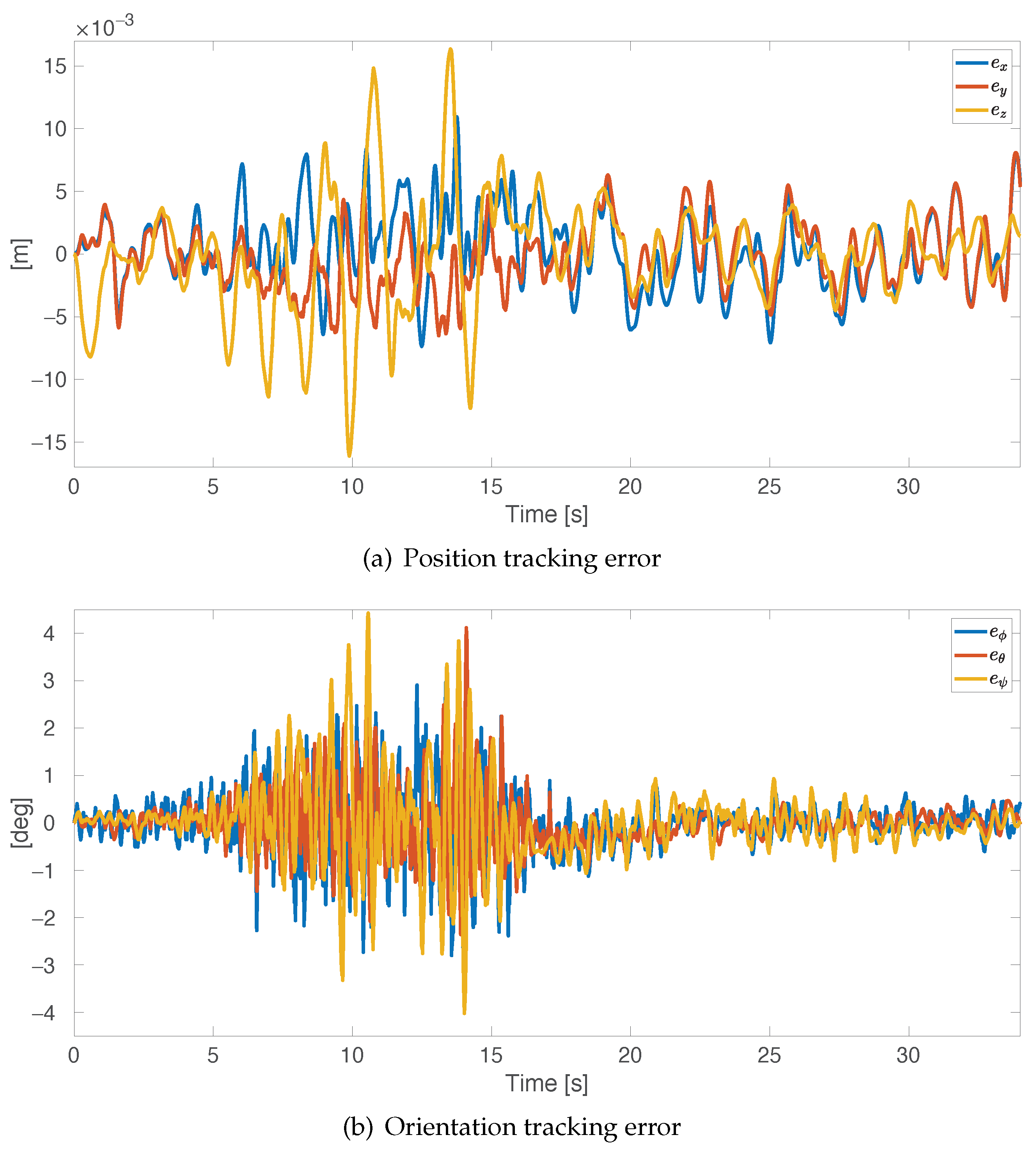
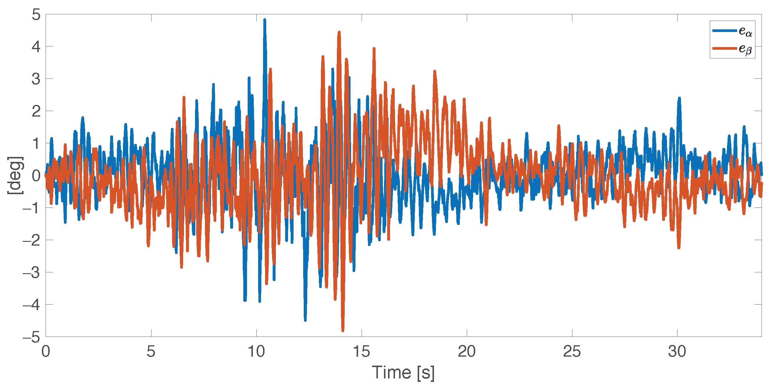
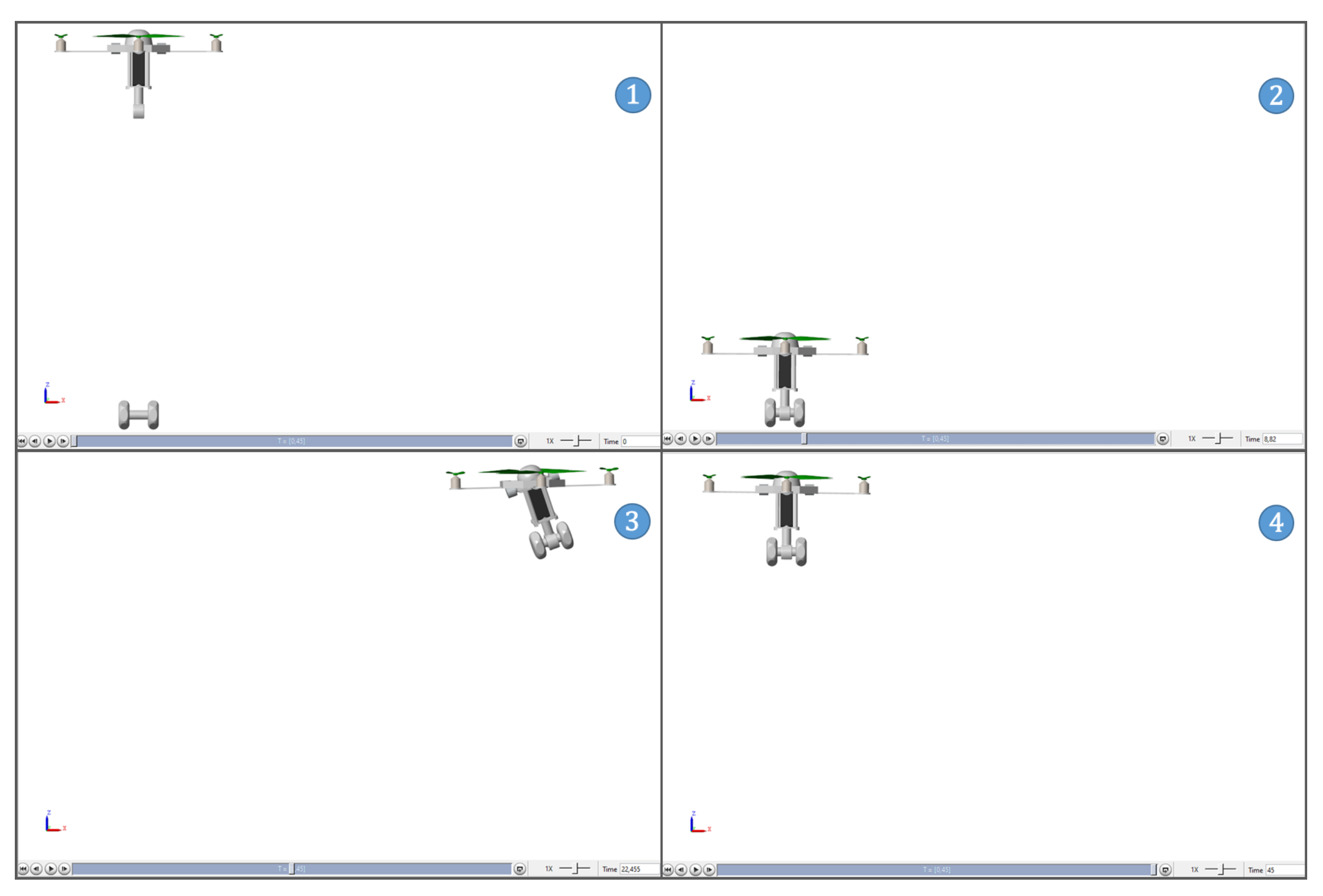
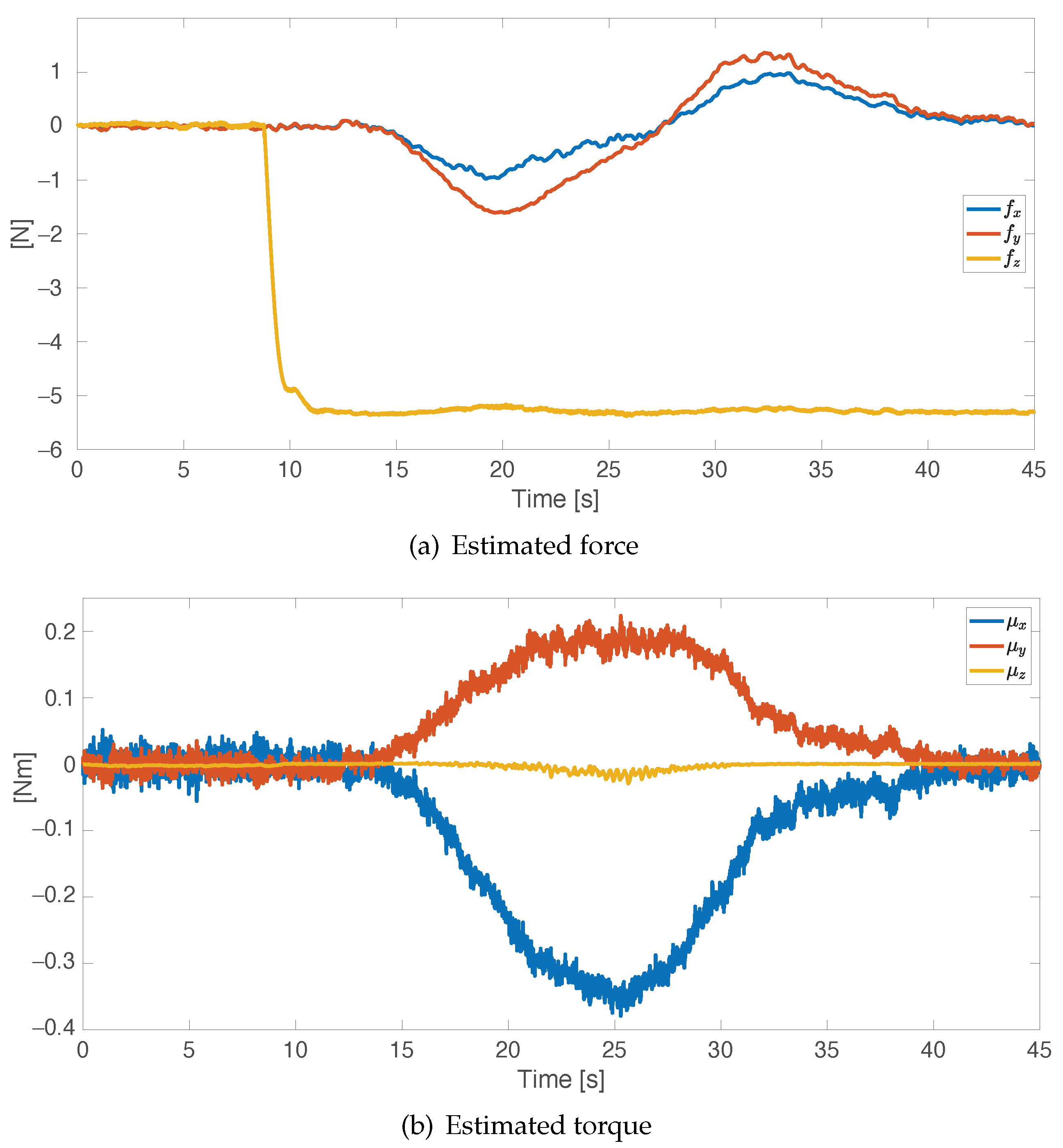
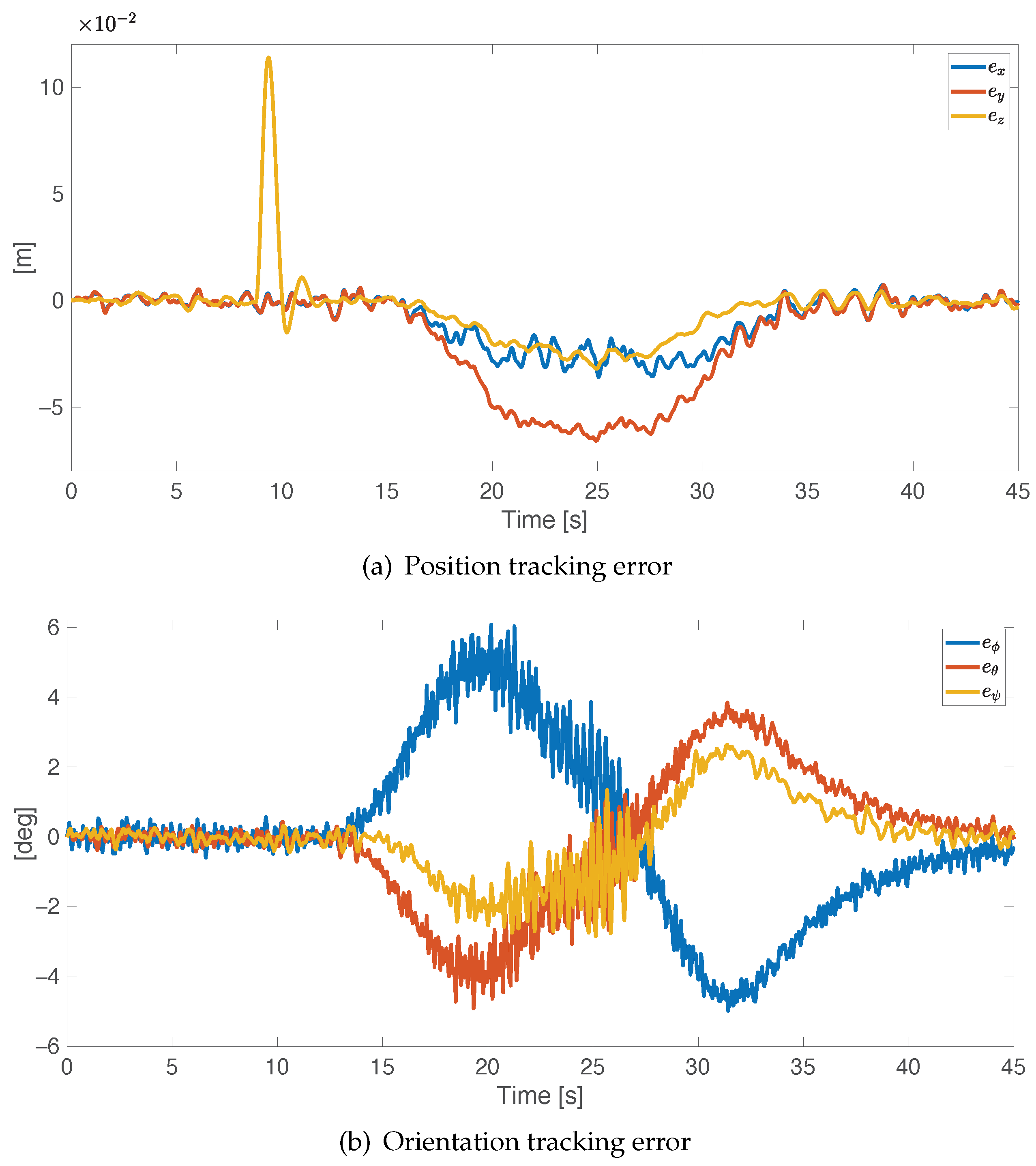
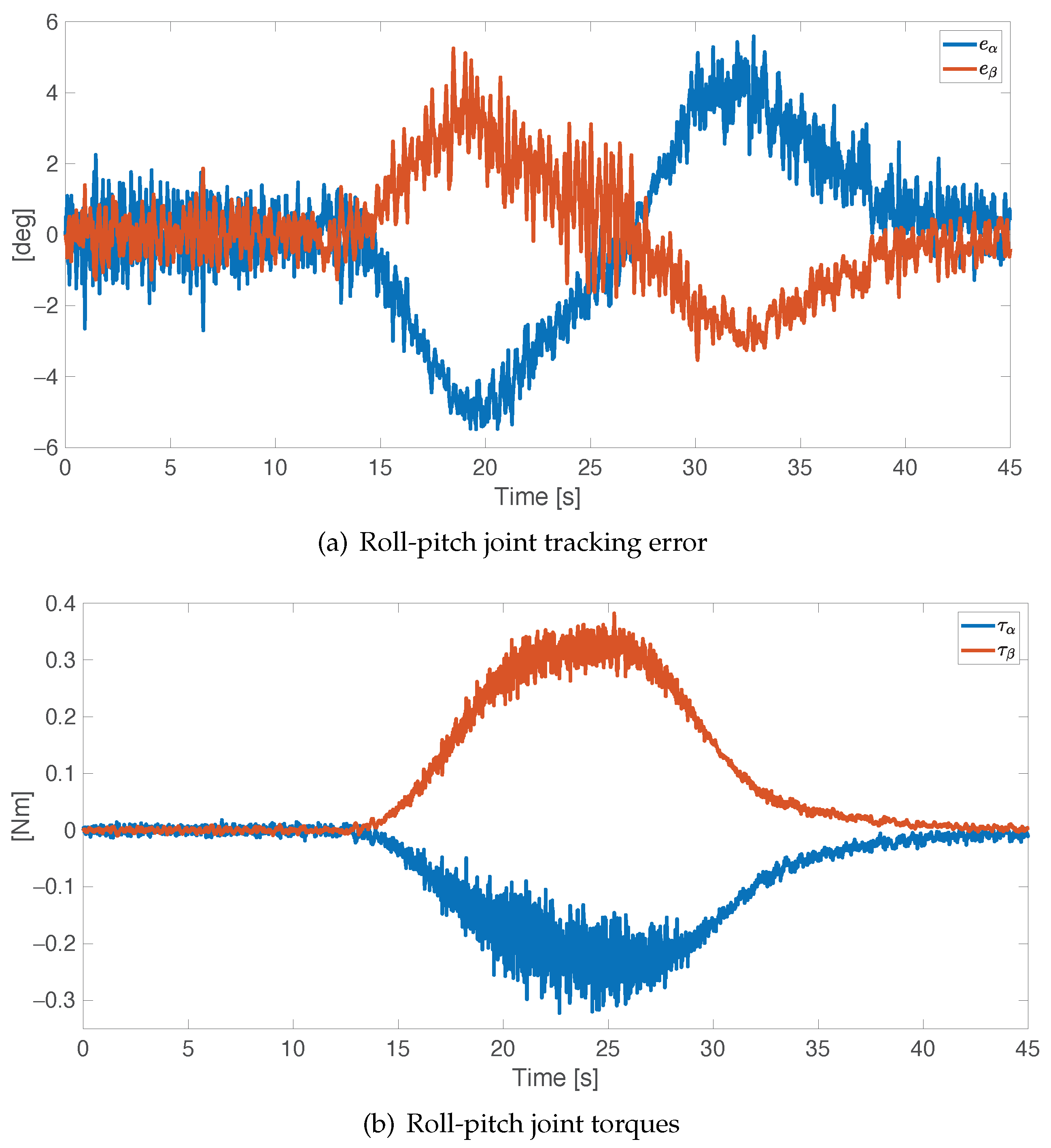
7. Simulation Results

The proposed controller has been tested via numerical simulation in the MATLAB© SimMechanics environment. The geometric and dynamic parameters of the ODQuad as well as details on the multi-body SimMechanics model can be found in [17]. In order to verify the effectiveness and the robustness of the controller, simulations in free-space motion and in the presence of contact with an object have been conducted. In the first one, in order to show the capability of controlling both position and orientation at same time, a trajectory in free-space has been commanded to the vehicle platform; in the latter simulation, the behavior in the presence of a task requiring grasp and transportation of an object has been tested.
The following realistic assumptions have been considered:
  • reliable, but noisy, measurements of the platform position and orientation are available, e.g., provided by a motion capture system and an IMU;
  • white noise has been added to measures of the platform position (with standard deviation 10 2 m) and orientation (with standard deviation 10 2 rad);
  • the angular positions of the roll and pitch joints are available via sensors usually integrated into the servomotors, while the angular velocities are obtained via numerical filtering. Thus, the orientation of the rotor frame relative to the platform frame can be computed via (1);
  • centrifugal and Coriolis terms have been neglected in control laws (18), (28), and (29);
  • viscous friction has been included in the simulation model but not considered in the control design.
The control gains that are reported in Table 1 have been tuned via a trial-and-error procedure by taking into account that the internal loop must be faster than the outer one and with the goal of minimizing the tracking error. The observer gain is reported in Table 2, and it has been set via a trial-and-error procedure by looking for the best trade-off between the convergence rate and the robustness to measurement noise.
In order verify the trajectory tracking capabilities, in the first simulation case study, time-varying desired position (see Figure 3a) and orientation (see Figure 3b) are commanded to the ODQuad platform. As previously remarked, it is worth noticing that, differently from common quadrotors, motion involving all six degrees of freedom can been assigned.
The obtained results are reported in Figure 4a,b in terms of position ( p 0 , d p 0 ) and orientation ( ϕ 0 , d ϕ 0 ) errors. In both cases, satisfactory performance is achieved, since the maximum position error is about 5 mm along the axes x and y and 15 mm along the z axis, while the orientation error oscillates around zero, with some peaks below 5 deg.
The performance of the internal control loop is measured by the roll-pitch joint tracking errors (( α d e s α ) and ( β d e s β )), reported in Figure 5. Furthermore, in this case, the peak error is below 5 deg, and the oscillation magnitude is about 2 degrees.
The second simulation case study is aimed to prove the controller robustness in the presence of an external disturbance. In this case, the control outputs (18), (28), and (29) are replaced by (48). A task involving grasping and transportation of an object has been considered: the ODQuad moves to the grasping point, grasps the object, and then rigidly holds it during its motion. Figure 6 shows some snapshots of the simulation.
The position tracking error, reported in Figure 7a, increases along the z axis during the grasping phase (at about 10 s), as expected, and comes back to the initial value after 3 s. In other words, after an initial transition due to the first contact with the object, the wrench estimator allows to correctly compensate the effect of the additional load attached to the vehicle.
Then, during the transportation, an error is experienced along the y axis and in the platform orientation (with a peak of about 6 deg), probably due to the dynamics of the gimbal mechanism.
Figure 8a reports the roll-pitch joint tracking errors: the roll and pitch errors during the transportation oscillate between −5 and 5 deg. Figure 8b reports the actuation torques of the roll-pitch joints: it can be noticed that, even in the presence of an external load, the required effort can be easily obtained via off-the-shelf motors.
Finally, the estimated interaction forces and torques, computed via the observer (52), are reported in Figure 9a,b. In detail, the force along z axis correctly converges to the load weight (Figure 9a), while small forces along x and y axes are experienced during the transportation, due to the object inertia and the unmodeled ODQuad’s dynamics (Coriolis and friction terms are neglected both in controller and in observer). Regarding the estimated torques (Figure 9b), small torques are experienced around the x and y axes due to the misalignment during the motion between the object and the platform CoM.

8. Discussion

This paper has reported the design and verification of a model-based motion control scheme for an omnidirectional UAV, the ODQuad, enriched with a wrench estimation approach to manage situations in which contact with the external environment is involved. Verification has been carried out via simulations, where the simulation model includes several real-world effects (e.g., measurement noise, unmodeled friction). The results confirm that the adopted control scheme achieves satisfactory performance in terms of tracking capabilities of free-space motion as well as of correct estimation and compensation of the contact wrench. This work is part of a long-term project aimed at developing a complete prototype of the ODQuad. Ongoing work is indeed focused on the mechanical, hardware, and software development of the ODQuad. Current research work is focused on the experimental verification of the designed control scheme on the developed prototype, as well as on the design and verification of interaction control schemes for tasks involving contact with the external environment.

Author Contributions

All authors contributed equally to this work. Conceptualization, M.N., F.P. and F.C.; methodology, M.N., F.P. and F.C.; software, M.N.; validation, M.N. and F.P.; formal analysis, M.N., F.P. and F.C.; investigation, M.N., F.P. and F.C.; resources, F.P. and F.C.; writing—original draft preparation, M.N.; writing—review and editing, F.P. and F.C.; funding acquisition, F.C. All authors have read and agreed to the published version of the manuscript.

Funding

This research received no external funding.

Institutional Review Board Statement

Not applicable.

Informed Consent Statement

Not applicable.

Conflicts of Interest

The authors declare no conflict of interest.

Abbreviations

The following abbreviations are used in this manuscript:
CoMCenter of Mass
DOFDegree of Freedom
ODQuadOmniDirectional Quadrotor
UAVUnmanned Aerial Vehicles

References

  1. Jordan, S.; Moore, J.; Hovet, S.; Box, J.; Perry, J.; Kirsche, K.; Lewis, D.; Tse, Z.T.H. State-of-the-art technologies for UAV inspections. IET Radar Sonar Navig. 2017, 12, 151–164. [Google Scholar] [CrossRef]
  2. Alejo, D.; Cobano, J.A.; Heredia, G.; Martínez-de Dios, J.R.; Ollero, A. Cooperative Robots and Sensor Networks 2015; Springer International Publishing: Cham, Switzerland, 2015; pp. 53–75. [Google Scholar]
  3. Tokekar, P.; Vander Hook, J.; Mulla, D.; Isler, V. Sensor planning for a symbiotic UAV and UGV system for precision agriculture. IEEE Trans. Robot. 2016, 32, 1498–1511. [Google Scholar] [CrossRef]
  4. Augugliaro, F.; Lupashin, S.; Hamer, M.; Male, C.; Hehn, M.; Mueller, M.W.; Willmann, J.S.; Gramazio, F.; Kohler, M.; D’Andrea, R. The Flight Assembled Architecture installation: Cooperative construction with flying machines. IEEE Control. Syst. Mag. 2014, 34, 46–64. [Google Scholar]
  5. Caccavale, F.; Giglio, G.; Muscio, G.; Pierri, F. Cooperative impedance control for multiple UAVs with a robotic arm. In Proceedings of the 2015 IEEE/RSJ International Conference on Intelligent Robots and Systems (IROS), Hamburg, Germany, 28 September–3 October 2015; pp. 2366–2371. [Google Scholar]
  6. Pierri, F.; Nigro, M.; Muscio, G.; Caccavale, F. Cooperative manipulation of an unknown object via omnidirectional unmanned aerial vehicles. J. Intell. Robot. Syst. 2020, 100, 1635–1649. [Google Scholar] [CrossRef]
  7. Nonami, K.; Kendoul, F.; Suzuki, S.; Wang, W. Atonomous Flying Robots, Unmanned Aerial Vehicles and Micro Aerial Vehicles; Springer: London, UK, 2010. [Google Scholar]
  8. Ryll, M.; Muscio, G.; Pierri, F.; Cataldi, E.; Antonelli, G.; Caccavale, F.; Bicego, D.; Franchi, A. 6D interaction control with aerial robots: The flying end-effector paradigm. Int. J. Robot. Res. 2019, 38, 1045–1062. [Google Scholar] [CrossRef] [Green Version]
  9. Ryll, M.; Bülthoff, H.H.; Giordano, P.R. A novel overactuated quadrotor unmanned aerial vehicle: Modeling, control, and experimental validation. IEEE Trans. Control. Syst. Technol. 2015, 23, 540–556. [Google Scholar] [CrossRef] [Green Version]
  10. Segui-Gasco, P.; Al-Rihani, Y.; Shin, H.S.; Savvaris, A. A novel actuation concept for a multi rotor UAV. J. Intell. Robot. Syst. 2014, 74, 173–191. [Google Scholar] [CrossRef]
  11. Rajappa, S.; Ryll, M.; Bülthoff, H.H.; Franchi, A. Modeling, control and design optimization for a fully-actuated hexarotor aerial vehicle with tilted propellers. In Proceedings of the IEEE International Conference on Robotics and Automation (ICRA), Seattle, WA, USA, 26–30 May 2015; pp. 4006–4013. [Google Scholar]
  12. Ryll, M.; Bicego, D.; Franchi, A. Modeling and control of FAST-Hex: A fully-actuated by synchronized-tilting hexarotor. In Proceedings of the IEEE/RSJ International Conference on Intelligent Robots and Systems (IROS), Daejeon, Korea, 9–14 October 2016. [Google Scholar]
  13. Kamel, M.S.; Verling, S.; Elkhatib, O.; Sprecher, C.; Wulkop, P.; Jeremy Taylor, Z.; Siegwart, R.; Gilitschenski, I. The Voliro Omnidirectional Hexacopter: An Agile and Maneuverable Tiltable-Rotor Aerial Vehicle. IEEE Robot. Autom. Mag. 2018, 25, 34–44. [Google Scholar] [CrossRef] [Green Version]
  14. Tognon, M.; Franchi, A. Omnidirectional aerial vehicles with unidirectional thrusters: Theory, optimal design, and control. IEEE Robot. Autom. Lett. 2018, 3, 2277–2282. [Google Scholar] [CrossRef] [Green Version]
  15. Hamandi, M.; Sawant, K.; Tognon, M.; Franchi, A. Omni-Plus-Seven (O7+): An Omnidirectional Aerial Prototype with a Minimal Number of Unidirectional Thrusters. In Proceedings of the 2020 International Conference on Unmanned Aircraft Systems (ICUAS), Athens, Greece, 1–4 September 2020; pp. 754–761. [Google Scholar]
  16. Odelga, M.; Stegagno, P.; Bülthoff, H.H. A fully actuated quadrotor UAV with a propeller tilting mechanism: Modeling and control. In Proceedings of the 2016 IEEE International Conference on Advanced Intelligent Mechatronics (AIM), Banff, AB, Canada, 12–15 July 2016; pp. 306–311. [Google Scholar]
  17. Nigro, M.; Pierri, F.; Caccavale, F. Preliminary design, modeling and control of a fully actuated quadrotor uav. In Proceedings of the 2019 International Conference on Unmanned Aircraft Systems (ICUAS), Atlanta, GA, USA, 11–14 June 2019; pp. 1108–1116. [Google Scholar]
  18. Hoffmann, G.; Huang, H.; Waslander, S.; Tomlin, C. Quadrotor helicopter flight dynamics and control: Theory and experiment. In Proceedings of the AIAA Guidance, Navigation, and Control Conference and Exhibit, Keystone, CO, USA, 21–24 August 2007. [Google Scholar]
  19. Araar, O.; Aouf, N. Full linear control of a quadrotor UAV, LQ vs. ∞. In Proceedings of the 2014 UKACC International Conference on Control (CONTROL), Loughborough, UK, 9–11 July 2014; pp. 133–138. [Google Scholar]
  20. Bangura, M.; Mahony, R. Real-time model predictive control for quadrotors. Ifac Proc. Vol. 2014, 47, 11773–11780. [Google Scholar] [CrossRef]
  21. Antonio-Toledo, M.E.; Sanchez, E.N.; Alanis, A.Y.; Flórez, J.; Perez-Cisneros, M.A. Real-time integral backstepping with sliding mode control for a quadrotor UAV. IFAC-PapersOnLine 2018, 51, 549–554. [Google Scholar] [CrossRef]
  22. Nadda, S.; Swarup, A. Development of backstepping based sliding mode control for a quadrotor. In Proceedings of the 2014 IEEE 10th International Colloquium on Signal Processing and Its Applications, Kuala Lumpur, Malaysia, 7–9 March 2014; pp. 10–13. [Google Scholar]
  23. Palunko, I.; Cruz, P.; Fierro, R. Agile load transportation. Safe and efficient load manipulation with aerial robots. IEEE Robot. Autom. Mag. 2012, 19, 69–79. [Google Scholar] [CrossRef]
  24. Ruggiero, F.; Cacace, J.; Sadeghian, H.; Lippiello, V. Passivity-based control of VToL UAVs with a momentum-based estimator of external wrench and unmodeled dynamics. Robot. Auton. Syst. 2015, 72, 139–151. [Google Scholar] [CrossRef]
  25. Forte, F.; Naldi, R.; Macchelli, A.; Marconi, L. Impedance control of an aerial manipulator. In Proceedings of the American Control Conference (ACC), 2012, Montreal, QC, Canada, 27–29 June 2012; pp. 3839–3844. [Google Scholar]
  26. Watterson, M.; Zahra, A.; Kumar, V. Geometric Control and Trajectory Optimization for Bidirectional Thrust Quadrotors. In Proceedings of the International Symposium on Experimental Robotics, Buenos Aires, Argentina, 5–8 November 2018; pp. 165–176. [Google Scholar]
  27. Meraglia, S.; Lovera, M. Smoother-Based Iterative Learning Control for UAV Trajectory Tracking. IEEE Control. Syst. Lett. 2021, 6, 1501–1506. [Google Scholar] [CrossRef]
  28. Park, S.; Her, J.; Kim, J.; Lee, D. Design, modeling and control of omni-directional aerial robot. In Proceedings of the 2016 IEEE/RSJ International Conference on Intelligent Robots and Systems (IROS), Daejeon, Korea, 9–14 October 2016; pp. 1570–1575. [Google Scholar]
  29. Ducard, G.; Hua, M.D. Discussion and practical aspects on control allocation for a multi-rotor helicopter. Int. Arch. Photogramm. Remote Sens. Spat. Inf. Sci. 2011, 38, 95–100. [Google Scholar] [CrossRef] [Green Version]
  30. Convens, B.; Merckaert, K.; Nicotra, M.M.; Naldi, R.; Garone, E. Control of fully actuated unmanned aerial vehicles with actuator saturation. IFAC-PapersOnLine 2017, 50, 12715–12720. [Google Scholar] [CrossRef]
  31. Nicotra, M.M.; Naldi, R.; Garone, E. A robust explicit reference governor for constrained control of unmanned aerial vehicles. In Proceedings of the 2016 American Control Conference (ACC), Boston, MA, USA, 6–8 July 2016; pp. 6284–6289. [Google Scholar]
  32. Franchi, A.; Carli, R.; Bicego, D.; Ryll, M. Full-pose tracking control for aerial robotic systems with laterally bounded input force. IEEE Trans. Robot. 2018, 34, 534–541. [Google Scholar] [CrossRef] [Green Version]
  33. Hamandi, M.; Usai, F.; Sablé, Q.; Staub, N.; Tognon, M.; Franchi, A. Design of multirotor aerial vehicles: A taxonomy based on input allocation. Int. J. Robot. Res. 2021, 40, 1015–1044. [Google Scholar] [CrossRef]
  34. Siciliano, B.; Sciavicco, L.; Villani, L.; Oriolo, G. Robotics—Modelling, Planning and Control; Springer: London, UK, 2009. [Google Scholar]
  35. Pierri, F.; Muscio, G.; Caccavale, F. An adaptive hierarchical control for aerial manipulators. Robotica 2018, 36, 1527–1550. [Google Scholar] [CrossRef] [Green Version]
  36. Reger, J.; Ramírez, H.S.; Fliess, M. On non-asymptotic observation of nonlinear systems. In Proceedings of the IEEE Conference on Decision and Control and European Control Conference CDC-ECC’05, Seville, Spain, 12–15 December 2005; pp. 4219–4224. [Google Scholar]
  37. Pereira, F.M. Block matrices and stability theory. Tatra Mt. Math. Publ. 2007, 38, 147–162. [Google Scholar]
  38. Siciliano, B.; Villani, L. An adaptive force/position regulator for robot manipulators. Int. J. Adapt. Control. Signal Process. 1993, 7, 389–403. [Google Scholar] [CrossRef]
  39. Khalil, H. Nonlinear Systems, 3rd ed.; Prentice Hall: Upper Saddle River, NJ, USA, 2002. [Google Scholar]
  40. Cataldi, E.; Muscio, G.; Trujillo, M.A.; Rodríguez, Y.; Pierri, F.; Antonelli, G.; Caccavale, F.; Viguria, A.; Chiaverini, S.; Ollero, A. Impedance control of an aerial-manipulator: Preliminary results. In Proceedings of the 2016 IEEE/RSJ International Conference on Intelligent Robots and Systems (IROS), Daejeon, Korea, 9–14 October 2016; pp. 3848–3853. [Google Scholar]
  41. De Luca, A.; Mattone, R. Sensorless robot collision detection and hybrid force/motion control. In Proceedings of the 2005 IEEE International Conferenc on Robotics and Automation, Barcelona, Spain, 18–22 April 2005; pp. 999–1004. [Google Scholar]
Figure 1. Roll joint axis (a), pitch joint axis (b).
Applsci 11 10991 g001
Figure 2. Block scheme of the overall control architecture, including the two loop controller, the interaction force estimator, and the propeller’s thrust mapping.
Applsci 11 10991 g002
Figure 3. First case study: desired position and orientation trajectories for the platform.
Applsci 11 10991 g003
Figure 4. First case study: position and orientation tracking errors.
Applsci 11 10991 g004
Figure 5. First case study: roll-pitch joint errors.
Applsci 11 10991 g005
Figure 6. Second case study: screenshots of Matlab’s Mechanics Explore. (1) ODQuad stays in hovering position. (2) ODQuad grasps the object, (3) ODQuad performs a position and orientation trajectory. (4) ODQuad comes to the initial configuration moving the grasped object.
Applsci 11 10991 g006
Figure 7. Second case study: platform position and orientation tracking errors.
Applsci 11 10991 g007
Figure 8. Second case study: roll-pitch joint tracking error (a) and torques (b).
Applsci 11 10991 g008
Figure 9. Second case study: estimated wrench.
Applsci 11 10991 g009
Table 1. Gain matrices for the auxiliary inputs (19), (20) and (27).
GainValueGainValueGainValue
  K P , p 25 0 0 0 25 0 0 0 25 K D , p 6.3 0 0 0 6.3 0 0 0 6.3 K I , p 0.025 0 0 0 0.025 0 0 0 0.025
  K P , ϕ 375 0 0 0 375 0 0 0 125 K D , ϕ 25.5 0 0 0 25.5 0 0 0 8.5 K I , ϕ 150 0 0 0 150 0 0 0 50
K P , δ 375 0 0 375 K D , δ 25.5 0 0 25.5 K I , δ 150 0 0 150
Table 2. Momentum observer gain.
GainValue
K o diag 1000 1000 1000 400 400 35 200 200
Publisher’s Note: MDPI stays neutral with regard to jurisdictional claims in published maps and institutional affiliations.

