Article

Local Failure Modes and Critical Buckling Loads of a Meta-Functional Auxetic Sandwich Core for Composite Bridge Bearing Applications

by
Pasakorn Sengsri
and
Sakdirat Kaewunruen
*
Laboratory for Track Engineering and Operations for Future Uncertainties (TOFU Lab), School of Engineering, The University of Birmingham, Edgbaston, Birmingham B15 2TT, UK
*
Author to whom correspondence should be addressed.
Appl. Sci. 2021, 11(22), 10844; https://doi.org/10.3390/app112210844
Submission received: 27 October 2021 / Revised: 10 November 2021 / Accepted: 16 November 2021 / Published: 17 November 2021
(This article belongs to the Special Issue Extreme Sciences and Engineering Ⅱ)

Abstract

:
This paper presents a novel meta-functional auxetic unit (MFAU) cell designed to improve performance and weight ratio for structural bridge bearing applications. Numerical investigations were conducted using three-dimensional finite element models validated by experimental results. The validated models were exposed to compression and buckling actions to identify structural failure modes, with special attention placed on the global behaviours of the meta-functional auxetic (MFA) composite bridge bearing. This bearing uses an unprecedented auxetic sandwich core design consisting of multiple MFAU cells. Numerical predictions of the elastic local critical buckling loads of the MFAU cell were in excellent agreement with both the analytical and experimental results, with an observed discrepancy of less than 1%. These results demonstrate that local buckling failures of MFAU cells can potentially be incurred prior to yielding under compression due to their slenderness ratios. Surprisingly, the designed sandwich core used in the MFA composite bridge bearing model can mimic an auxetic structure with significant crashworthiness, implying that this novel core composite structure can be tailored for structural bridge bearing applications. Parametric studies were thus carried out in order to enrich our insight into the MFA composite elements. These insights, stemming from both experimental and numerical studies, enable a novel design paradigm for MFAU that can significantly enhance the structural performance of MFA composite bridge bearings in practice.

1. Introduction

To date, one of the most widely adopted design approaches for highway bridges subject to static and dynamic conditions is the performance-based design concept [1,2,3]. As such, a designer needs better insight into structural requirements and responses in order to determine failure modes of each individual component of a bridge structure prior to the installation of metamaterials in practice. Common elastomeric bridge bearings, also called laminated rubber bearings (LRBs), are comprised of rubber layers and steel shims, resulting in a tradeoff between horizontal flexibility and high vertical stiffness. During dynamic loading, these bearings are vital components in a bridge system because they must alternately experience vertical forces and large horizontal displacements induced by the bridge deck. This leads to tensile (uplift) and compressive deformation to the LRBs, due to the rotation of a pier cap around a transverse axis [4]. In addition, these bearings are vulnerable to tensile loading, resulting in local failures in the interior of rubber as a well-known cavitation phenomenon if they are not bolted through top and bottom external plates [5,6,7,8]. Unlike compression loading, the rubber is capable of easily sustaining large pressures without sustaining damage, as the tensile stresses are very low during the initial cavitation stage [6]. Under exceptional earthquakes, the horizontal displacement can range from 150 percent to more than 300 percent shear strain. Another failure of rubber bearings is rollover for dowelled bearings [9]. These limit states are not examined in this work.
In our previous work [10], we reviewed numerous recent studies on the development of elastomeric bridge bearings using fibre reinforcement (fibre-reinforced rubber bearings, FRRBs), which exhibit improved mechanical properties [11,12,13,14,15,16,17,18,19,20,21,22]. In contrast to LRBs, the fibre reinforcement used in FRRBs offers such benefits as light weight, lower stresses in bearings, and simple installation [10]. Nevertheless, the materials used in these bearings, whether reinforced by steel or fibre, can be better designed in order to obtain specific properties under expected loading conditions using metamaterials which cannot be found in nature [23,24]. Their properties are obtained from the structural design rather than from their constituent materials. Recently, many researchers have investigated auxetic structures used for sandwich cores in a range of engineering applications. Auxetic structures possess the novel property of a negative Poisson’s ratio (PR) [9,25,26]. Negative PR materials are well-known for their excellent of lateral contraction behaviour and resistance to expansion when exposed to compression and tension, respectively [27,28,29,30,31,32,33,34]. While common natural materials, also referred to as positive PR materials, exhibit swell behaviour perpendicular to compressive loading and contraction behaviour under tensile loading, as given in Figure 1 [25,35], these auxetic materials provide a wide range of engineering advantages with superior mechanical properties such as shear resistance [9], higher fracture toughness, lower fatigue crack propagation [36,37,38,39,40,41], vibration mitigation [42], indentation resistance [43], crashworthiness [44,45], light weight [46], energy absorption [47,48], etc.
Therefore, auxetic structures are likely to be the ideal core for sandwich panels. A conventional sandwich panel consists of a lightweight core, for instance honeycomb [49,50,51,52,53,54,55], foam [56,57,58], etc. They are adhesively connected to two relatively thin facets which have high stiffness and strength. Numerous studies have been performed on sandwich panels with a two-dimensional auxetic metamaterial core to determine their vibration and bending behaviours [49,50,51,52,53,54,55]. On the other hand, there are only a few studies regarding sandwich panels with a three-dimensional auxetic lattice metamaterial core. In one study [59], it was found that the use of the designed auxetic cellular core had enhanced dynamic response. For impact resistance applications, sandwich plates with an auxetic lattice core confined between two thin metal facets have been proposed, and results show that the modelling of a lattice core can be used for beam components which have massive solid elements instead. On the other hand, to the best of our knowledge following a critical review of the available literature, there are no extant studies determining the local failure modes and critical buckling loads of a meta-functional auxetic sandwich core for bridge bearing applications.
In this paper, we present a new design and analysis of a novel unit cell structure with a negative Poisson’s ratio (which cannot be found in nature [23,24] but can be synthetically 3D-printed) for composite bridge bearings. This designed novel structure is investigated in order to identify its local failure modes and critical buckling loads under compression, as well as to observe the overall behaviour of an MFA composite bridge bearing model with an auxetic sandwich core made of these novel unit cells under compression. Additionally, the buckling failure curve of an MFAU cell is presented in order to predict its buckling behaviour for design and development in the near future. This proposed auxetic 3D unit cell, fabricated through additive manufacturing, should have an extensive range of versatility in applications including anomalous elastic wave polarization [60], acoustic metamaterials for dominated band gaps [61,62], and sandwich structure cores for bridge bearing applications under vibration. Numerical model design, including the 3D printed rubber-like material used, will be detailed in the following section, followed by the comparative results and discussion of the analytical and numerical buckling analysis. Furthermore, the model validation for additive manufacturing is conducted by comparing the numerical and experimental results.

2. A Numerical Model for an Auxetic Sandwich Core Used for Bridge Bearings

2.1. An MFAU Cell Computer-Aided Design (CAD) Model

In this section, the designed MFAU cell model of a sandwich core for bridge bearing is provided, as shown in Figure 2. It is characterised by a re-entrant shape and selected for its negative Poisson’s behaviour. Additionally, the selection of this structure is based on a relatively simple design that which is able to be produced by additive manufacturing. The MFAU cell has a three-dimensional geometry developed from a well-known two-dimensional re-entrant auxetic unit (AU). The benefit of using a 3D AU cell is that it allows for biaxial response in all loading directions, instead of the common uniaxial response of a 2D AU cell [63,64]. Compared to honeycomb structures, the MFAU cell designed in this paper is a truss-like structure for bridge bearing applications. Importantly, it maintains its auxetic behaviour at high strains, which is required for the exceptional loading conditions of bridge bearing designs. The configuration parameters used in this MFAU model include the length of the diagonal strut L, and two angles, β and α. The dimensions of the AU cell model are depicted in Figure 2, where L = 12.57 mm, β = 56.16°, and α = 37.30°. To avoid contact between the beams and ensure effective auxetic behaviour, these angle parameters are limited. The height of the beams set in the vertical direction is represented as m = 3 mm, while the connective beams set in the horizontal direction can be determined as n = L cos α sin β ( 1 tan α ) + 1 . The eight struts of the upper and lower bases have a square cross-section of width, w = 1.50 mm. Unlike the other beam components, they have a circular cross-section of radius, a = 1.50 mm. The MFAU cell has a square base, and the width is determined as K = 2 L cos α . The whole height of the model is M = 2 m + 2 L cos β , and the whole width is K . The thickness of all components is 1.50 mm. As demonstrated in Figure 2, the three-dimensional MFAU cell structure is 21.50 × 21.50 × 21.50 mm in size.

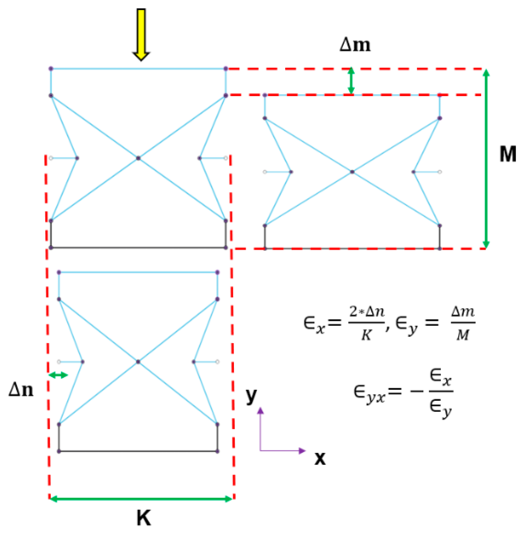
2.2. Effective Poisson’s Ratio of the MFAU Cell Model

Poisson’s ratio (PR) was first introduced by Simeon Dennis Poisson [65]. In this paper, the effective PR of the MFAU cell model is defined as the ratio of transverse engineering strain, induced by the lateral deformation, to axial engineering strain, which is induced by the vertical deformation. Figure 3 illustrates the procedure for determining the effective PR of the model. The lower base is simply supported in the vertical direction, while a uniform static force is applied on the upper base of the MFAU cell model.

3. Materials and Methods

In this work, we focused on the modes of local failures and the local critical buckling loads of a 3D novel auxetic unit cell for composite bridge bearings. Using a metastructure with negative Passions’ ratio, we observed the overall compressive behaviour of an MFA composite bridge bearing with an auxetic sandwich core in order to obtain its compressive stiffness. The MFAU cell can be fabricated via additive manufacturing from a thermoplastic polyurethane (TPU) material; because of its complex structure, traditional manufacturing is unable to meet the requirements. The TPU material is a common 3D printing material and possesses rubber-like properties. Hence, it shows high elasticity, flexibility, shock resistance, thermoplasticity, and high hardness, as well as outstanding abrasion and tear resistance [66,67,68]. For the material properties used in the MFAU cell and MFA composite bridge bearing models for simulations, TPU had the following properties [69]: Young’s modulus 2410 MPa; density 1235 kg/m3; Poisson’s ratio 0.39; yield strength 21 MPa; and ultimate tensile strength 38.4 MPa. In the MFA composite bridge bearing model, a proposed material for additive manufacturing shown in the application section which has more vertical stiffness than the TPU material was selected for simulation. In addition, a titanium carbide material was used for one facet connected to the auxetic sandwich core model due to its high strength-to-weight ratio and improved vertical stiffness for composite bridge bearing applications under compression.
The buckling analysis, in both analytical and numerical methods, was chosen because of the geometry of the model, which is a truss-like structure. It is important to mention that buckling is not a proportional phenomenon; it is instead likely to be a critical one. When the compression level is relatively low, the behaviour of the component shows stability without overall buckling behaviour. However, when the compressive loading takes place at a critical level, the buckling behaviour appears suddenly. Obviously, the buckling corresponds to the stiffness of the component and not to its strength. In addition, the fully compressive behaviour of the composite bridge bearing with an auxetic sandwich core using the proposed material was investigated to observe its vertical stiffness, as presented in the result section. Model validation for the compression analysis was achieved by comparing the vertical stiffness between the numerical and experimental results.

3.1. Analytical Analysis

In analytical buckling analysis, Euler buckling theory is a fundamental theory elucidated in many reviews. It is important to note that the linear Euler buckling equation found in these reviews is valid only when the material is still within its elastic limit (that is, the critical slenderness ratio of a material, α c r i   , is less than the slenderness ratio of a column, α c o l ). The slenderness ratio α c o l is defined as L e f f   / R   , where R is the least radius of gyration; R is defined as I m i n A . The slenderness ratio of a material α c r i is expressed as 2 π 2 E σ y , where σ y is the yield strength of a material. However, if the value of α c r i is higher than the value of α c o l , the critical buckling load is calculated by using the Johnson equation, as shown below:
F c r i = A [ ( σ y ) 1 E ( σ y 2 π ) 2 ( α c o l ) 2 ] .
As mentioned, the classical buckling analysis does not depend on a material’s yield strength. Therefore, yield considerations are required in the buckling analysis of a column in order to obtain a stress (Euler’s load divided by the cross-section area of the column, A, given in the equation below) and compare this value to the yield strength of a material to identify a failure mode of the material under compression if yielding appears before buckling.
σ c r i = F c r i A  

3.2. Numerical Analysis

To conduct numerical analysis, two 3D CAD models for the MFAU cell and MFA composite bridge bearing using a sandwich core (5 × 5 × 3 unit cells) were generated by Fusion 360 software, as shown in Figure 4. Then, a 3D finite element method-based approach using Siemens NX 12.0 Nastran (Siemens, Munich, Germany) software was followed in order to simulate the analytical buckling analysis on the two column components (vertical and diagonal) of the MFAU cell, as shown in Figure 5c.
Two 3D column finite element models with the same boundary condition used in the analytical analysis (free–fixed) were produced, with 1925 and 5872 tetra10 elements for the vertical and diagonal columns, respectively. These two solid element models had a very refined mesh (0.2 mm element size). The compressive load of 1 N was applied to each component in the vertical direction, as shown in Figure 5a,b. When the simulation of the eigenvalue problem was carried out, the obtained buckling load factor, δ , was used for calculating critical loads for the two components. To obtain the critical loads, the initial compressive loads were multiplied by the buckling load factor, δ . Furthermore, the numerical investigation included the overall compressive behaviour of the MFAU cell under the highest local critical buckling load obtained. In terms of bridge bearing applications, a full three-dimensional model consisted of 13,319 and 2,301,690 tetra10 solid elements for the MFAU cell and MFA composite bridge bearing model, respectively. Their entire three-dimensional tetrahedral method is presented in Figure 5c,d. Both solid elements models had the same element size, 1 mm. The highest local critical buckling load face was imposed on the top surface of the MFAU cell model; for the other model, the enforced displacement constraint of 4 mm was applied to the top surface of a thin metallic facet connected to the top surface of the auxetic core by using a glue surface-to-surface contact. The base of each model was fixed.
Validation of the simulations was carried out by comparing the numerical critical buckling loads of the two column components of the MFAU cell with the analytical ones under the free-fixed condition, as shown in Figure 6. Under compression, the diagonal column showed an analytical critical buckling load of 9.68 N and a numerical one of 9.74 N (relative error 0.62 per cent), while in the case of the vertical column it presented an analytical critical buckling load of 108.28 N and a numerical one of 109.55 N (relative error 0.70 per cent). In fact, the relative error of the vertical column would be higher if the actual critical buckling load were calculated from the Johnson formula instead of the Euler formula, due to the slenderness ratio of the TPU material being less than the critical one.

4. Results

The analytical and numerical results presented herein were obtained using a Johnson–Euler buckling approach and the finite element method (FEM), using Siemens NX 12.0 Nastran (Siemens, Munich, Germany) software for the analytical and numerical approaches, respectively.

4.1. Analytical Results

Table 1 presents the analytical results of the critical Euler and yield load analysis for each component of the MFAU cell, based on the linear Euler and Johnson theory. In this section, the critical slenderness ratio of the TPU material, α c r i , is compared with that of each column component, α c o l . As mentioned, if the slenderness ratio of a material is less than that of each column component, the Euler theory is valid for the analysis, while if the value of α c r i is higher than the value of α c o l , the Johnson theory is employed instead. As can be seen in Table 1, the two column components of the MFAU cell model, which are set for a free-fixed boundary condition, fail in buckling before yielding under uniaxial compression. It is important to mention that this boundary condition was chosen because it can potentially predict the critical buckling load in a worst-case design, and because it is difficult to identify the boundary conditions of both columns in the MFAU cell model due to its complex geometry.
Nevertheless, the value of the critical buckling load of the vertical column is close to the load at the yield point of the TPU material. This means that the failure behaviour of the vertical column can alternately fail in buckling and yielding if the higher load level is applied to the MFAU cell model. While the critical load of the diagonal column is 0.26× of the yield load of the material, the column first shows buckling behaviour in the linear elastic region before yielding as the compressive loading is applied. It is worth noting that the independent buckling behaviour of each component will be provided in the following section through the numerical results.

4.2. Numerical Results

The results of the finite element model calculations in this paper are based on linear Euler buckling theory. Obviously, the numerical results of the critical buckling load analysis for the diagonal column are in good agreement with the analytical solutions, as shown in Table 2, while in the case of the vertical column there is a large difference in the critical buckling load analysis between the numerical and analytical results. This is because the critical buckling load obtained from the FEM tends to overestimate Euler’s critical load when the critical slenderness ratio of a material is higher than that of a column. To address this issue, the nonlinear Euler buckling analysis should be conducted and compared to the critical buckling load obtained from the analytical calculation using the Johnson equation, which is more accurate for the calculation in this case. It is important to mention that in this paper we focus on the linear buckling analysis in order to identify the local failure modes of a meta-functional auxetic unit cell for bridge bearing using a linear isotropic material, which at low strain is TPU. Furthermore, Figure 7 and Figure 8 demonstrate the numerical buckling behaviour (including displacement and stress distribution) of the vertical and diagonal columns with a free–fixed boundary condition under compression, respectively.
Therefore, it can be concluded that the local buckling behaviours of the MFAU cell using a TPU material with rubber-like properties for bridge bearing applications are dominated by the diagonal column at the critical buckling load of 9.74 N, and that local buckling failure occurs in both columns before yielding. Furthermore, the results of the overall behaviours of the MFAU cell and the MFA composite bridge bearing both exhibit auxetic behaviour (contraction) under compression and have a local buckling failure located on the vertical and diagonal columns, as shown in Figure 9 and Figure 10.
For the bridge bearing applications, we found that the previous MFAU cell model using a TPU material was not suitable for the applications due to its low compressive stiffness. Therefore, in this paper, the selection of an optimised material for the MFA composite bridge bearing model was considered, especially for Young’s modulus, in order to act as a typical bridge bearing. The variation of the mechanical properties used in this model is given in Table 3. Surprisingly, the auxetic sandwich core used in the MFA composite bridge bearing model (given in Figure 11) was still stable in the vertical direction under compression, while the core showed auxetic behaviour. In addition, Figure 12 demonstrates that the appearance of individual area corresponds to the mechanisms of deformation and the interactions among these novel unit cells at different strain regions (0, 20, and 40 per cent of strain, respectively), which has been widely investigated in many studies.
In order to validate the MFA composite bridge bearing model for practical use, Figure 13 shows the comparative results for vertical stiffness of the model with various Young’s moduli, presented in Table 3, and a common bridge bearing under compression at a vertical displacement of 4 mm, comparing numerical predictions and experimental measurements, respectively. It is clear that there is a small difference in vertical stiffness between the numerical and observed experimental results on the curve of the figure, with the proposed material having a compressive stiffness close to that typical of the common bridge bearing used in the model (less than 0.78%). This means the proposed model acts as a typical bridge bearing which can possibly resist the weight of a superstructure of a common bridge. However, the model should be further investigated using static and dynamic shear analysis in order to ensure better performance in reality. Note that the proposed material is considered as a linear material and the proposed model would be fabricated using a 3D printed composite with a high stiffness to density ratio (Cyanate ester/HM carbon fibre) composed of polymer (30%) and carbon fibre (60%), as obtained from the CES Edupack 2019 (Granta Design, Cambridge, UK) [70] software and as given in Figure 14. The experimental measurements are based on the journal provided in [71].

5. Conclusions

In this article, we have proposed a novel 3D meta-functional auxetic unit (MFAU) cell with a negative Poisson’s ratio (NPR) for 3D printed composite bridge bearing applications. Experimental results have been used to validate numerical models. The models have been used for parametric studies and tailored design of the MFAU in order to develop new insights. The key benefit of using a designed structure with NPR is a high-performance to weight ratio. Their performance under compression was analytically and numerically studied, considering the local buckling failures and also determining the critical buckling loads and the buckling failure curve of the MFAU cell. Validation of the proposed model for additive manufacturing was conducted to obtain vertical stiffness by comparing experimental results. Major conclusions include:
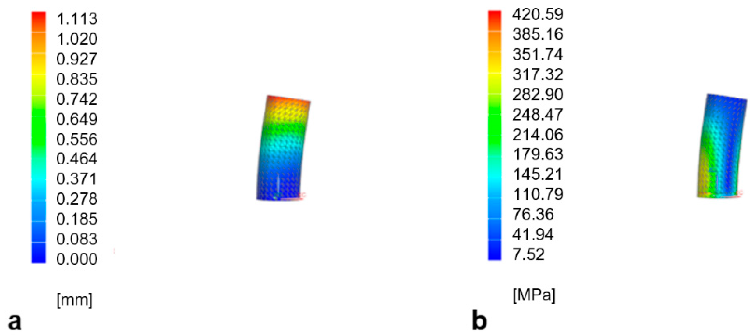
  • Local buckling failure can potentially appear before yielding in the vertical and diagonal columns of the MFAU cell under compression.
  • The comparative results of the critical buckling load analysis of the vertical and diagonal column between the analytical solutions and the numerical predictions are in good agreement, with less than 0.70% and 0.62%, respectively, when the TPU material is in a linear elastic regime.
  • The failure curve of the MFAU cell model has been identified in order to predict its local buckling phenomena based on the slenderness ratios.
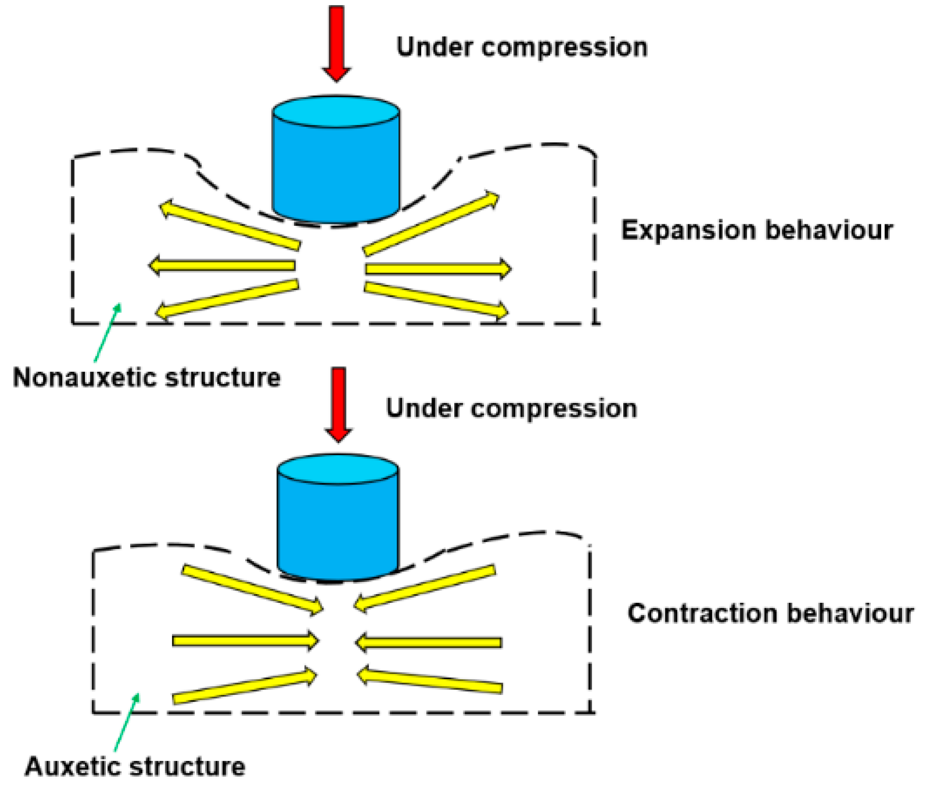
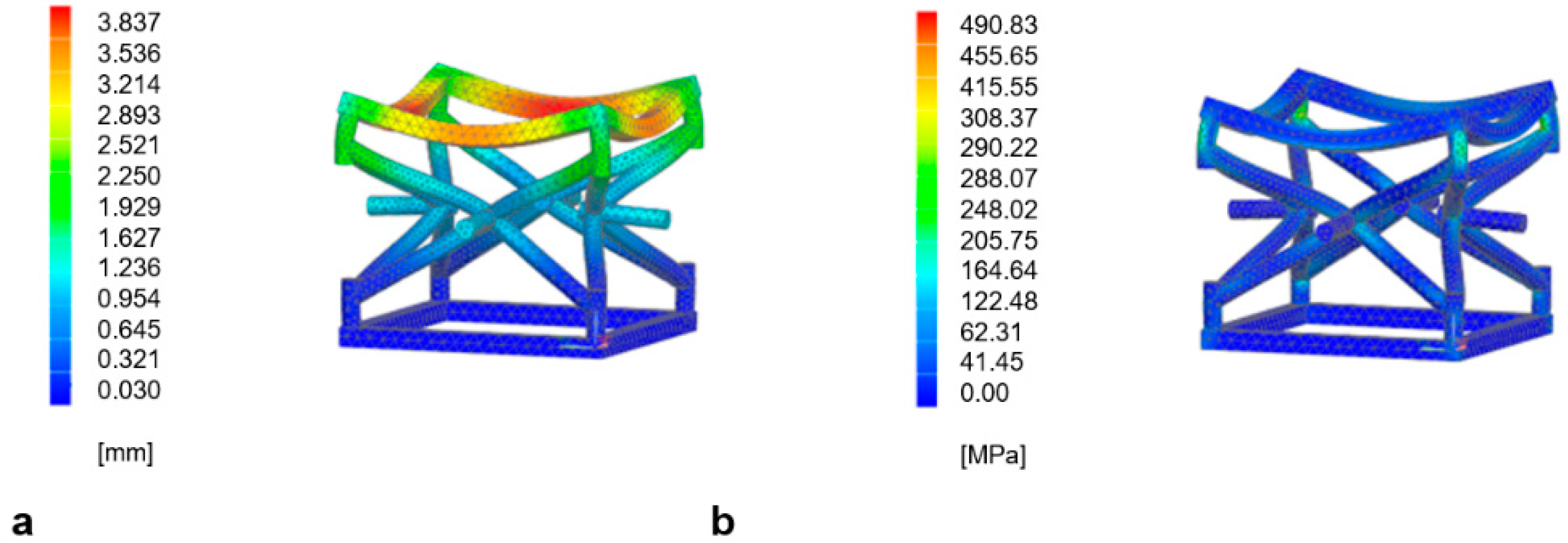
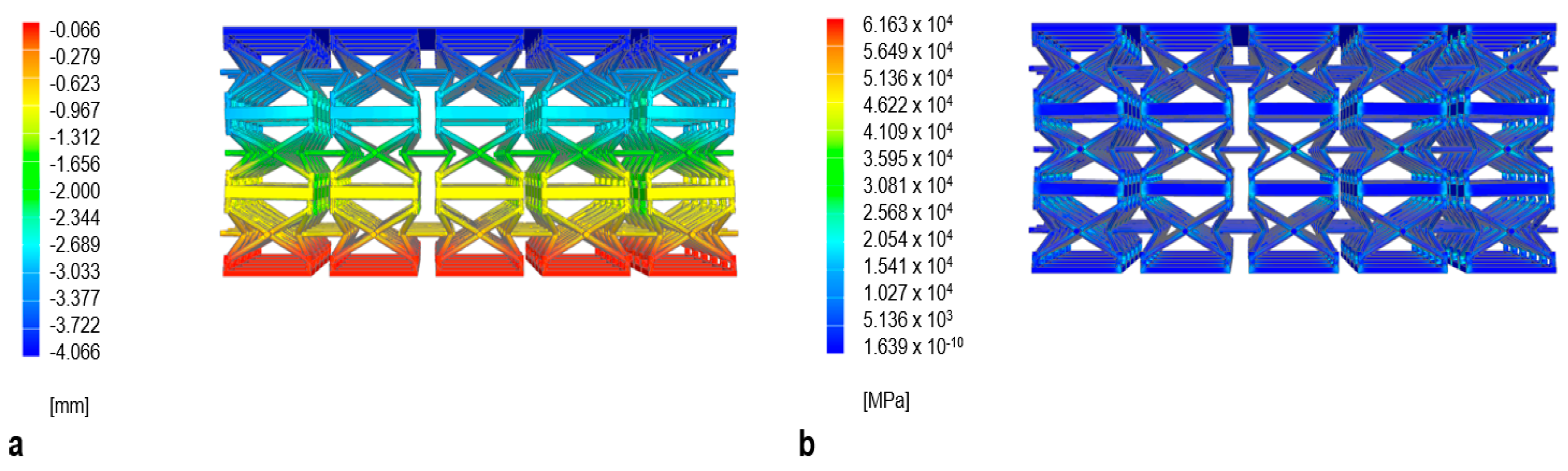
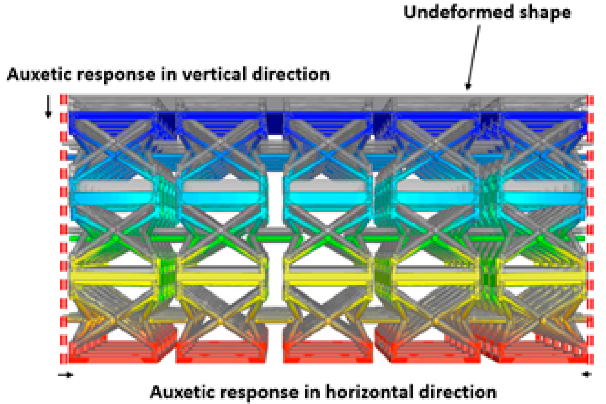
  • For bridge bearing applications, the overall compressive behaviour of the MFA composite bridge bearing model shows auxetic behaviour (contraction), with promising crashworthiness under compression.
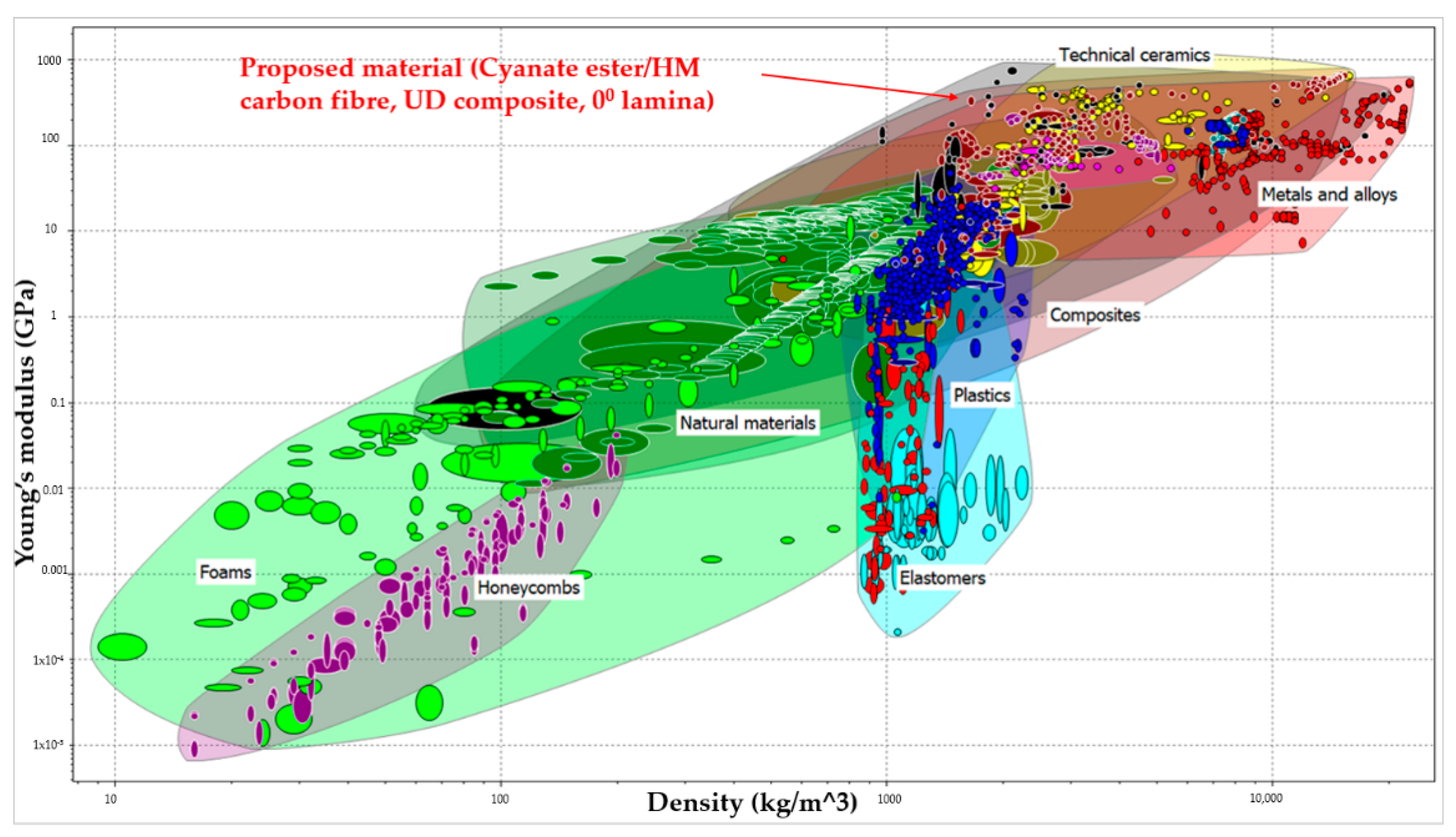
  • For additive manufacturing, the findings in this paper indicate that the MFA composite bridge bearing model using a proposed material can, when compared to experimental results, perform well under compression as a common bridge bearing. Thus, fabrication by 3D printing and the development of this design for application could be possible for practical use in the near future.
In short, robust analyses demonstrate that the proposed novel 3D auxetic sandwich core model is promising for composite bridge bearing applications. Further studies on the compression–shear behaviour of this novel core model for different environmental conditions will be presented in the future.

Author Contributions

Conceptualization, S.K.; methodology, S.K.; software, S.K.; validation, P.S.; formal analysis, P.S.; investigation, S.K., P.S.; resources, S.K.; writing—original draft preparation, P.S.; writing—review and editing, S.K.; visualization, P.S.; supervision, S.K.; project administration, S.K.; funding acquisition, S.K. All authors have read and agreed to the published version of the manuscript.

Funding

This research was funded by European Commission, grant numbers: H2020-MSCA-RISE No. 691135. The APC was funded by the University of Birmingham Library’s Open Access Fund.

Institutional Review Board Statement

Not applicable.

Informed Consent Statement

Not applicable.

Data Availability Statement

The data that support the findings of this study are available from the corresponding author upon reasonable request.

Acknowledgments

The first author wishes to thank the Royal Thai Government for his Scholarship at the University of Birmingham. The last author wishes to gratefully acknowledge the Japan Society for Promotion of Science (JSPS) for his JSPS Invitation Research Fellowship (long-term), Grant No. L15701, at the Track Dynamics Laboratory, Railway Technical Research Institute and at Concrete Laboratory, the University of Tokyo, Tokyo, Japan. The JSPS financially supports this work as part of the research project, entitled ‘‘Smart and reliable railway infrastructure”. Special thanks to the European Commission for H2020-MSCA-RISE Project No. 691135 ‘‘RIS-EN: Rail Infrastructure Systems Engineering Network” (www.risen2rail.eu) [72]. Partial support from H2020 Shift2Rail Project No. 730849 (S-Code) is acknowledged. In addition, the sponsorships and assistance from LORAM, Network Rail, RSSB (Rail Safety and Standard Board, UK) are highly appreciated.

Conflicts of Interest

The authors declare no conflict of interest.

References

  1. AASHTO. Guide Specifications for Seismic Isolation Design, 3rd ed.; American Association of State Highway and Transportation Officials: Washington, DC, USA, 2010. [Google Scholar]
  2. CSA. S6-14—Canadian Highway Bridge Design Code; Canadian Standards Association: Toronto, ON, Canada, 2014. [Google Scholar]
  3. Priestley, M.; Calvi, G.; Kowalsky, M. Displacement-Based Seismic Design of Structures; IUSS Press: Pavia, Italy, 2007. [Google Scholar]
  4. Kelly, J. Dynamic and Failure Characteristics of Bridgestone Bearings; Tech rep UCB/EERC-91/04; Earthquake Engineering Research Center, University of California: Berkeley, CA, USA, 1991. [Google Scholar]
  5. Gent, A.N.; Lindley, P.B. Internal rupture of bonded rubber cylinders in tension. Proc. R. Soc. Math. Phys. Eng. Sci. 1959, 249, 195–205. [Google Scholar] [CrossRef]
  6. Gent, A.N. Cavitation in Rubber: A Cautionary Tale. Rubber Chem. Technol. 1990, 63, 49–53. [Google Scholar] [CrossRef]
  7. Pond, T.J. Cavitation in bonded natural rubber cylinders repeatedly loaded in tension. J. Nat. Rubber Res. 1995, 10, 14–25. [Google Scholar]
  8. Dorfmann, A.; Burtscher, S.L. Aspects of Cavitation Damage in Seismic Bearings. J. Struct. Eng. 2000, 126, 573–579. [Google Scholar] [CrossRef]
  9. Lakes, R. Foam Structures with a Negative Poisson’s Ratio. Science 1987, 235, 1038–1040. [Google Scholar] [CrossRef] [PubMed]
  10. Sengsri, P.; Kaewunruen, S. Additive manufacturing meta-functional composites for engineered bridge bearings: A review. Constr. Build. Mater. 2020, 262, 120535. [Google Scholar] [CrossRef]
  11. Al-Anany, Y.; Van Engelen, N.; Tait, M.; Konstantinidis, D. Examination of Fiber Reinforced Elastomeric Isolators for Bridge Applications, In Proceedings of the 8th World Congress on Joints, Bearings and Seismic Systems for Concrete Structures, International Joints and Bearings Research Council, Atlanta, GA, USA, 25–29 September 2016.
  12. Ashkezari, G.D.; Aghakouchak, A.A.; Kokabi, M. Design, manufacturing and evaluation of the performance of steel like fiber reinforced elastomeric seismic isolators. J. Mater. Process. Technol. 2008, 197, 140–150. [Google Scholar] [CrossRef]
  13. Kang, B.-S.; Kang, G.-J.; Moon, B.-Y. Hole and lead plug effect on fiber reinforced elastomeric isolator for seismic isolation. J. Mater. Process. Technol. 2003, 140, 592–597. [Google Scholar] [CrossRef]
  14. Kelly, J. Analysis of fiber-reinforced elastomeric isolators. J. Seismol. Earthq. Eng. 1999, 2, 19–34. [Google Scholar]
  15. Kelly, J.M. Seismic Isolation Systems for Developing Countries. Earthq. Spectra 2002, 18, 385–406. [Google Scholar] [CrossRef]
  16. Moon, B.-Y.; Kang, G.-J.; Kang, B.-S.; Kelly, J.M. Design and manufacturing of fiber reinforced elastomeric isolator for seismic isolation. J. Mater. Process. Technol. 2002, 130–131, 145–150. [Google Scholar] [CrossRef]
  17. Mordini, A.; Strauss, A. An innovative earthquake isolation system using fibre reinforced rubber bearings. Eng. Struct. 2008, 30, 2739–2751. [Google Scholar] [CrossRef]
  18. Naghshineh, A.K.; Akyüz, U.; Caner, A. Comparison of fundamental properties of new types of fiber-mesh-reinforced seismic isolators with conventional isolators. Earthq. Eng. Struct. Dyn. 2014, 43, 301–316. [Google Scholar] [CrossRef]
  19. Naghshineh, A.K.; Akyüz, U.; Caner, A. Lateral Response Comparison of Unbonded Elastomeric Bearings Reinforced with Carbon Fiber Mesh and Steel. Shock. Vib. 2015, 2015, 1–10. [Google Scholar] [CrossRef] [Green Version]
  20. Toopchi-Nezhad, H.; Tait, M.J.; Drysdale, R.G. Testing and modeling of square carbon fiber-reinforced elastomeric seismic isolators. Struct. Control. Health Monit. 2007, 15, 876–900. [Google Scholar] [CrossRef]
  21. Toopchi-Nezhad, H.; Tait, M.J.; Drysdale, R.G. Lateral Response Evaluation of Fiber-Reinforced Neoprene Seismic Isolators Utilized in an Unbonded Application. J. Struct. Eng. 2008, 134, 1627–1637. [Google Scholar] [CrossRef]
  22. Van Engelen, N. Adaptive Characteristics of Fiber-Reinforced Elastomeric Isolator. Ph.D. Thesis, McMaster University, Hamilton, ON, Canada, 2015. [Google Scholar]
  23. Kolken, H.M.A.; Zadpoor, A.A. Auxetic mechanical metamaterials. RSC Adv. 2017, 7, 5111–5129. [Google Scholar] [CrossRef] [Green Version]
  24. Kshetrimayum, R. A brief intro to metamaterials. IEEE Potentials 2004, 23, 44–46. [Google Scholar] [CrossRef]
  25. Evans, K.E.; Nkansah, M.A.; Hutchinson, I.J.; Rogers, S.C. Molecular network design. Nat. Cell Biol. 1991, 353, 124. [Google Scholar] [CrossRef]
  26. Lakes, R. Response: Negative Poisson’s ratio materials. Science 1987, 238, 551. [Google Scholar] [CrossRef]
  27. Yang, L.; Harrysson, O.; West, H.; Cormier, D. Mechanical properties of 3D re-entrant honeycomb auxetic structures realized via additive manufacturing. Int. J. Solids Struct. 2015, 69–70, 475–490. [Google Scholar] [CrossRef]
  28. Wang, X.-T.; Li, X.-W.; Ma, L. Interlocking assembled 3D auxetic cellular structures. Mater. Des. 2016, 99, 467–476. [Google Scholar] [CrossRef] [Green Version]
  29. Xue, Y.; Gao, P.; Zhou, L.; Han, F. An Enhanced Three-Dimensional Auxetic Lattice Structure with Improved Property. Mater. 2020, 13, 1008. [Google Scholar] [CrossRef] [PubMed] [Green Version]
  30. Faraci, D.; Driemeier, L.; Comi, C. Bending-Dominated Auxetic Materials for Wearable Protective Devices against Impact. J. Dyn. Behav. Mater. 2021, 7, 425–435. [Google Scholar] [CrossRef]
  31. Madke, R.R.; Chowdhury, R. Anti-impact behavior of auxetic sandwich structure with braided face sheets and 3D re-entrant cores. Compos. Struct. 2020, 236, 111838. [Google Scholar] [CrossRef]
  32. Lim, T.C. Auxetic Materials and Structures; Springer: Singapore, 2015. [Google Scholar] [CrossRef]
  33. Hu, H.; Zhang, M.; Liu, Y. Auxetic Textiles; Elsevier: Amsterdam, The Netherlands, 2019. [Google Scholar] [CrossRef]
  34. Lim, T.-C. Mechanics of Metamaterials with Negative Parameters. Suppl. Cem. Mater. 2020. [Google Scholar] [CrossRef]
  35. Saxena, K.K.; Das, R.; Calius, E. Three Decades of Auxetics Research − Materials with Negative Poisson’s Ratio: A Review. Adv. Eng. Mater. 2016, 18, 1847–1870. [Google Scholar] [CrossRef]
  36. Alderson, A.; Alderson, K. Auxetic materials. J. Aerosp. Eng. 2007, 221, 565–575. [Google Scholar] [CrossRef]
  37. Evans, K.E.; Alderson, A. Auxetic materials: Functional materials and structures from lateral thinking! Adv. Mater. 2000, 12, 617. [Google Scholar] [CrossRef]
  38. Argatov, I.I.; Guinovart-Díaz, R.; Sabina, F.J. On local indentation and impact compliance of isotropic auxetic materials from the continuum mechanics viewpoint. Int. J. Eng. Sci. 2012, 54, 42–57. [Google Scholar] [CrossRef]
  39. Pasternak, E.; Dyskin, A. Materials and structures with macroscopic negative Poisson’s ratio. Int. J. Eng. Sci. 2012, 52, 103–114. [Google Scholar] [CrossRef]
  40. Zhang, X.-C.; An, L.-Q.; Ding, H.-M.; Zhu, X.-Y.; El-Rich, M. The influence of cell micro-structure on the in-plane dynamic crushing of honeycombs with negative Poisson’s ratio. J. Sandw. Struct. Mater. 2014, 17, 26–55. [Google Scholar] [CrossRef]
  41. Scarpa, F.; Yates, J.; Ciffo, L.G.; Patsias, S. Dynamic crushing of auxetic open-cell polyurethane foam. Proc. Inst. Mech. Eng. Part J. Mech. Eng. Sci. 2002, 216, 1153–1156. [Google Scholar] [CrossRef]
  42. Chekkal, I.; Remillat, C.; Scarpa, F. Acoustic properties of auxetic foams. High Perform. Struct. Mater. VI 2012, 124, 119–129. [Google Scholar] [CrossRef] [Green Version]
  43. Hu, L.L.; Deng, H. Indentation resistance of the re-entrant hexagonal honeycombs with negative poisson’s ratio. Mater. Res. Innov. 2015, 19, S1-442–S1-445. [Google Scholar] [CrossRef]
  44. Hou, S.; Liu, T.; Zhang, Z.; Han, X.; Li, Q. How does negative Poisson’s ratio of foam filler affect crashworthiness? Mater. Des. 2015, 82, 247–259. [Google Scholar] [CrossRef]
  45. Mohsenizadeh, S.; Alipour, R.; Rad, M.S.; Nejad, A.F.; Ahmad, Z. Crashworthiness assessment of auxetic foam-filled tube under quasi-static axial loading. Mater. Des. 2015, 88, 258–268. [Google Scholar] [CrossRef]
  46. Compton, B.G.; Lewis, J.A. 3D-Printing of Lightweight Cellular Composites. Adv. Mater. 2014, 26, 5930–5935. [Google Scholar] [CrossRef] [PubMed]
  47. Fleck, N.A.; Deshpande, V.; Ashby, M.F. Micro-architectured materials: Past, present and future. Proc. R. Soc. A Math. Phys. Eng. Sci. 2010, 466, 2495–2516. [Google Scholar] [CrossRef]
  48. Li, D.; Yin, J.; Dong, L.; Lakes, R.S. Strong re-entrant cellular structures with negative Poisson’s ratio. J. Mater. Sci. 2018, 53, 3493–3499. [Google Scholar] [CrossRef]
  49. Whitty, J.; Alderson, A.; Myler, P.; Kandola, B. Towards the design of sandwich panel composites with enhanced mechanical and thermal properties by variation of the in-plane Poisson’s ratios. Compos. Part A Appl. Sci. Manuf. 2003, 34, 525–534. [Google Scholar] [CrossRef]
  50. Scarpa, F.; Tomlinson, G. Theoretical characteristics of the vibration of sandwich plates with in-plane negative poisson’s ratio values. J. Sound Vib. 2000, 230, 45–67. [Google Scholar] [CrossRef]
  51. Duc, N.D.; Cong, P.H. Nonlinear dynamic response and vibration of sandwich composite plates with negative Poisson’s ratio in auxetic honeycombs. J. Sandw. Struct. Mater. 2018, 20, 692–717. [Google Scholar]
  52. Cong, P.H.; Khanh, N.D.; Khoa, N.D.; Duc, N.D. New approach to investigate nonlinear dynamic response of sandwich auxetic double curves shallow shells using TSDT. Compos. Struct. 2018, 185, 455–465. [Google Scholar] [CrossRef]
  53. Duc, N.D.; Seung-Eock, K.; Cong, P.H.; Anh, N.T.; Khoa, N.D. Dynamic response and vibration of composite double curved shallow shells with negative Poisson’s ratio in auxetic honeycombs core layer on elastic foundations subjected to blast and damping loads. Int. J. Mech. Sci. 2017, 133, 504–512. [Google Scholar] [CrossRef]
  54. Hajmohammad, M.H.; Nouri, A.H.; Zarei, M.S.; Kolahchi, R. A new numerical approach and visco-refined zigzag theory for blast analysis of auxetic honeycomb plates integrated by multiphase nanocomposite facesheets in hygrothermal environment. Eng. Comput. 2019, 35, 1141–1157. [Google Scholar] [CrossRef]
  55. Hajmohammad, M.H.; Kolahchi, R.; Zarei, M.S.; Nouri, A.H. Dynamic response of auxetic honeycomb plates integrated with agglomerated CNT-reinforced face sheets subjected to blast load based on visco-sinusoidal theory. Int. J. Mech. Sci. 2019, 153-154, 391–401. [Google Scholar] [CrossRef]
  56. Wang, J.; Wang, H.; Chen, X.; Yu, Y. Experimental and numerical study of the elastic properties of PMI foams. J. Mater. Sci. 2010, 45, 2688–2695. [Google Scholar] [CrossRef]
  57. Wang, J.; Waas, A.M.; Wang, H. Experimental and numerical study on low-velocity impact behavior of foam-core sandwich panels. Compos. Struct. 2013, 96, 298–311. [Google Scholar] [CrossRef]
  58. Zhang, P.; Wang, Z.; Zhao, L. Dynamic crushing behavior of open-cell aluminum foam with negative Poisson’s ratio. Appl. Phys. A 2017, 123, 321. [Google Scholar] [CrossRef]
  59. Novak, N.; Starčevič, L.; Vesenjak, M.; Ren, Z. Blast response study of the sandwich composite panels with 3D chiral auxetic core. Compos. Struct. 2019, 210, 167–178. [Google Scholar] [CrossRef]
  60. Patil, G.U.; Shedge, A.B.; Matlack, K.H. 3D auxetic lattice materials for anomalous elastic wave polarization. Appl. Phys. Lett. 2019, 115, 091902. [Google Scholar] [CrossRef]
  61. Krödel, S.; Delpero, T.; Bergamini, A.; Ermanni, P.; Kochmann, D.M. 3D Auxetic Microlattices with Independently Controllable Acoustic Band Gaps and Quasi-Static Elastic Moduli. Adv. Eng. Mater. 2014, 16, 357–363. [Google Scholar] [CrossRef]
  62. Chen, M.; Xu, W.; Liu, Y.; Yan, K.; Jiang, H.; Wang, Y. Band gap and double-negative properties of a star-structured sonic metamaterial. Appl. Acoust. 2018, 139, 235–242. [Google Scholar] [CrossRef] [Green Version]
  63. Evans, A.; He, M.; Deshpande, V.; Hutchinson, J.; Jacobsen, A.; Carter, W. Concepts for enhanced energy absorption using hollow micro-lattices. Int. J. Impact Eng. 2010, 37, 947–959. [Google Scholar] [CrossRef] [Green Version]
  64. Imbalzano, G.; Tran, P.; Ngo, T.D.; Lee, P.V.S. A numerical study of auxetic composite panels under blast loadings. Compos. Struct. 2016, 135, 339–352. [Google Scholar] [CrossRef]
  65. Lee, S.; Barthelat, F.; Hutchinson, J.; Espinosa, H. Dynamic failure of metallic pyramidal truss core materials—Experiments and modeling. Int. J. Plast. 2006, 22, 2118–2145. [Google Scholar] [CrossRef]
  66. Hentschel, T.; Munstedt, H. Thermoplastic polyurethane the material used for the erlanger silver catheter. Infection 1999, 27, 43–45. [Google Scholar] [CrossRef]
  67. Burke, A.; Hasirci, N. Polyurethanes in Biomedical Applications. Adv. Exp. Med. Biol. 2004, 553, 83–101. [Google Scholar] [CrossRef]
  68. Mi, H.-Y.; Salick, M.R.; Jing, X.; Jacques, B.R.; Crone, W.C.; Peng, X.-F.; Turng, L.-S. Characterization of thermoplastic polyurethane/polylactic acid (TPU/PLA) tissue engineering scaffolds fabricated by microcellular injection molding. Mater. Sci. Eng. C 2013, 33, 4767–4776. [Google Scholar] [CrossRef] [Green Version]
  69. Lee, H.; Eom, R.-I.; Lee, Y. Evaluation of the Mechanical Properties of Porous Thermoplastic Polyurethane Obtained by 3D Printing for Protective Gear. Adv. Mater. Sci. Eng. 2019, 2019, 1–10. [Google Scholar] [CrossRef] [Green Version]
  70. Ashby, M.F. Materials Selection in Mechanical Design, 4th ed.; Butterwortg—Heinemann: New York, NY, USA, 2011. [Google Scholar]
  71. Mori, A.; Carr, A.; Cooke, N.; Moss, P. Compression behaviour of bridge bearings used for seismic isolation. Eng. Struct. 1996, 18, 351–362. [Google Scholar] [CrossRef]
  72. Kaewunruen, S.; Sussman, J.M.; Matsumoto, A. Grand Challenges in Transportation and Transit Systems. Front. Built Environ. 2016, 2, 4. [Google Scholar] [CrossRef] [Green Version]
Figure 1. Different behaviours of nonauxetic structure and auxetic structures under compression.
Applsci 11 10844 g001
Figure 2. Schematic design of a meta-functional auxetic unit cell.
Applsci 11 10844 g002
Figure 3. Effective Poisson’s ratio (EPR) determination for the MFAU cell.
Applsci 11 10844 g003
Figure 4. A three-dimensional CAD model for the meta-functional auxetic unit cell model (a) and composite bridge bearing model (b), respectively.
Applsci 11 10844 g004
Figure 5. A 3D solid element model of the vertical column (a), the diagonal column (b), the MFAU unit cell (c), and the MFA composite bridge bearing (d).
Applsci 11 10844 g005
Figure 6. Stress–slenderness ratio construction of an MFAU cell failure line.
Applsci 11 10844 g006
Figure 7. Displacement (a) and stress distribution (b) of the vertical column with free–fixed boundary condition in the buckling analysis.
Applsci 11 10844 g007
Figure 8. Displacement (a) and stress distribution (b) of the diagonal column with free–fixed boundary condition in the buckling analysis.
Applsci 11 10844 g008
Figure 9. Overall deformation (a) and stress distribution (b) of the meta-functional auxetic unit cell under compression at the highest critical buckling load.
Applsci 11 10844 g009
Figure 10. Overall deformation (a) and von Mises stress distribution (b) of the meta-functional auxetic composite bridge bearing model under compression at vertical displacement of 4 mm.
Applsci 11 10844 g010
Figure 11. Auxetic deformation behaviour of the meta-functional auxetic composite bridge bearing model in vertical and horizontal directions under compression at vertical displacement of 4 mm.
Applsci 11 10844 g011
Figure 12. The numerical auxetic deformation modes of this novel structure at different strain regions in the vertical and horizontal directions.
Applsci 11 10844 g012
Figure 13. A comparison of the vertical stiffness of the meta-functional auxetic composite bridge bearing model, with different Young’s moduli and a common bridge bearing at the vertical displacement of 4 mm, between numerical and experimental relationships, respectively.
Applsci 11 10844 g013
Figure 14. Young’s modulus–density Ashby diagram. The diagram compares the proposed material against alternative materials.
Applsci 11 10844 g014
Table 1. Analytical buckling results for both column components.
Vertical ColumnDiagonal Column
α c r i < α c o l 47.60 > 2047.60 < 67.04
TheoryJohnsonEuler
F c r i (N)34.009.68
P y (N)37.1737.17
σ c r i (MPa)19.215.47
σ y (MPa)21.0021.00
Mode of failureBucklingBuckling
Table 2. Numerical buckling results for both column components.
Vertical ColumnDiagonal Column
Buckling load factor, δ 109.559.74
F a p p l i e d (N)11
F c r i (N)109.559.74
Relative error ( % ) , compared to analytical resultsoverestimation0.62
Type of failureBucklingBuckling
Table 3. The various Young’s moduli used in the MFA composite bridge bearing model.
SimulationYoung’s Modulus, E (GPa)
Model 1200
Model 2300
Proposed model350
Model 3400
Publisher’s Note: MDPI stays neutral with regard to jurisdictional claims in published maps and institutional affiliations.

