Article

Spectral Characteristics of the Double-Folded Slot Antennas with Cold-Electron Bolometers for the 220/240 GHz Channels of the LSPE Instrument

by
Leonid S. Revin
1,2,
Dmitry A. Pimanov
2,
Anton V. Blagodatkin
1,2,
Anna V. Gordeeva
1,2,
Andrey L. Pankratov
1,2,
Alexander V. Chiginev
1,2,
Igor V. Rakut’
1,2,
Viktor O. Zbrozhek
2,
Leonid S. Kuzmin
2,3,*,
Silvia Masi
4 and
Paolo de Bernardis
4
1
Institute for Physics of Microstructures of RAS, GSP-105, 603950 Nizhny Novgorod, Russia
2
Superconducting Nanoelectronics Laboratory, Nizhny Novgorod State Technical University, n.a. R.E. Alekseev, 603950 Nizhny Novgorod, Russia
3
Microtechnology and Nanoscience Department, Chalmers University of Technology, 41296 Gothenburg, Sweden
4
Dipartimento di Fisica, Università La Sapienza, I-00185 Roma, Italy
*
Author to whom correspondence should be addressed.
Appl. Sci. 2021, 11(22), 10746; https://doi.org/10.3390/app112210746
Submission received: 14 October 2021 / Revised: 8 November 2021 / Accepted: 9 November 2021 / Published: 14 November 2021
(This article belongs to the Special Issue Design and Application of Cold-Electron Bolometers)

Abstract

:
We present the results of the experimental and theoretical study of the resonant properties and noise of a single cell of a receiving system based on cold-electron bolometers (CEB) with a double-folded slot antenna and coplanar lines. The system was designed to receive signals at 220/240 GHz frequencies with a 5% bandwidth. In measurements, we used the samples of the double-folded slot antennas with slot lengths of 162 um and coplanar line lengths from 185 to 360 um. Measurements of the resonance properties of CEB located at 0.3 K cryostat plate were carried out using a generator based on a high-temperature YBCO Josephson junction located inside the same cryostat at 4 K plate. This arrangement made it possible to obtain smooth amplitude-frequency characteristics with a clearly defined peak of a 15–21 GHz bandwidth at different frequencies. Based on these results, 2-D array of double-folded slot antennas with CEBs as 220/240 GHz LSPE channel prototype was calculated.The absorption efficiency of the array has reached 81% and 77% for 220 and 240 GHz channels, respectively.

1. Introduction

Current work is aimed at the creation of a bolometric system with an antenna and an on-chip filter as an application in ultra-sensitive balloon-borne receiving systems for the study of cosmic microwave background radiation (CMB)—one of the important and actual issues of modern astronomy and cosmology. The Large Scale Polarization Explorer (LSPE) [1] is an experiment of the Italian Space Agency for studying the polarization pattern of the B-mode of CMB. In this experiment, it is supposed to observe a signal at the central frequency of 145 GHz with a bandwidth of 30%, and at frequencies of 220 and 240 GHz (with a bandwidth of 5%). The channel of 145 GHz is the main one for measuring the CMB. The 220 GHz and 240 GHz bands are ancillary frequency channels. They are needed to eliminate the influence of cosmic dust radiation on the measurements of the CMB [2], giving the offset of the main channel. The main difficulty of this project is the creation of a two-channel system for frequencies of 220 GHz and 240 GHz with a small HPBW of 5%.
As sensitive radiation detectors for this project, we propose to use the cold-electron bolometers (CEBs) [3,4,5]. These detectors have several advantages: a wide dynamic range due to the presence of effective electron cooling [5,6], high sensitivity to the received useful signal [7], and low internal noise below the photon noise of incoming signal [7,8]. The CEBs are insensitive to cosmic rays because of the small absorber volume and weak coupling between the electron and phonon subsystems of the absorber at low temperatures [9]. Besides, CEBs have a compact size of the order of several microns, which allows them to be placed directly into the antenna slot or a cut of a coplanar line [10,11,12]. CEBs allow fabrication of the integrated on-chip filters, consisting of tunnel superconducting-insulator-normal metal (SIN) capacitances, antenna and coplanar reactances.

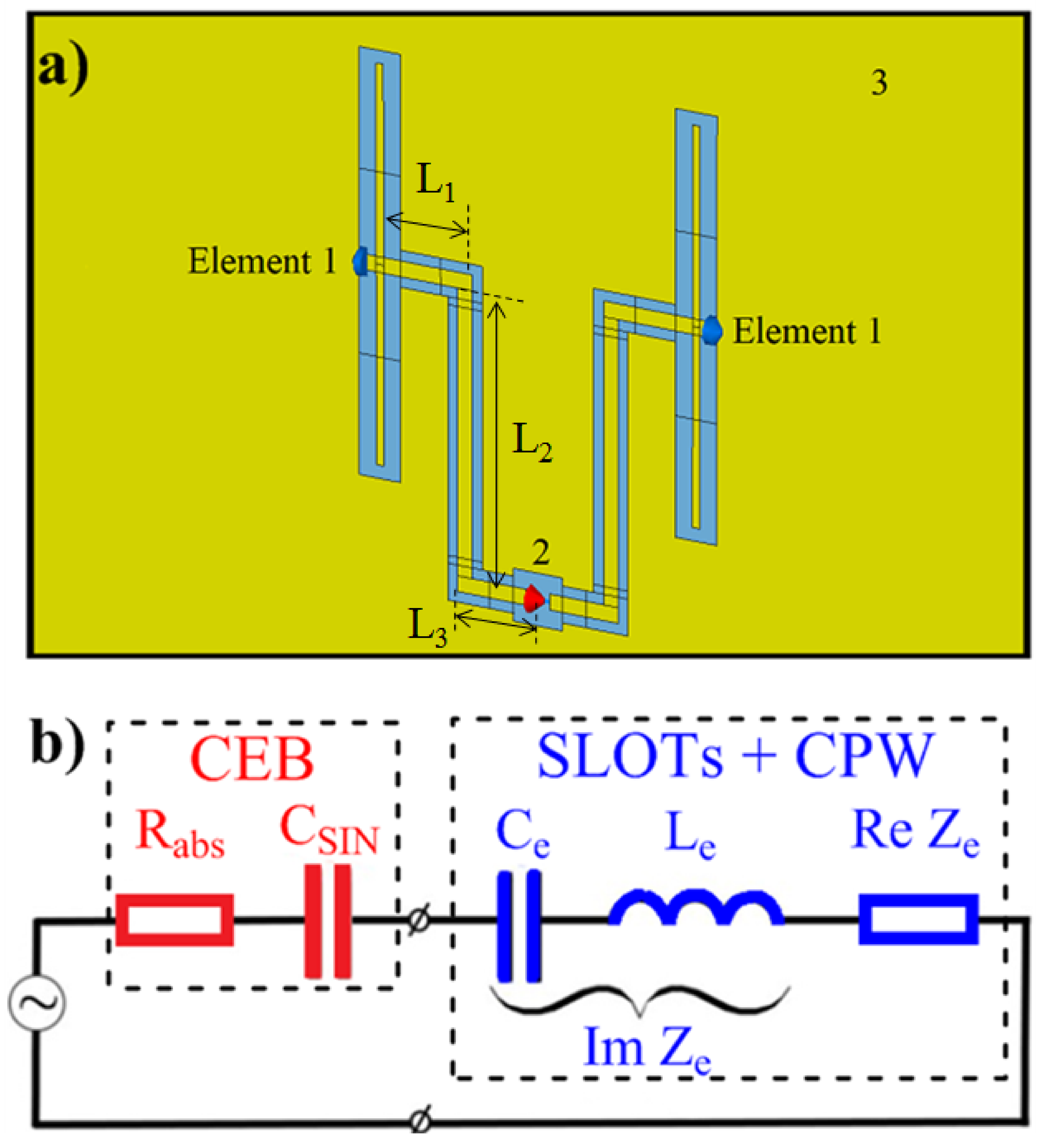
2. Electromagnetic Model

As a model of the antenna cell, we use a double slot antenna. These antennas have been tested with various sensors, such as bismuth bolometers [13], quasioptical SIS mixers [14], and so on. The concept of double slot antenna has also been applied in the seashell antenna [11,12,15,16] which has been designed for use with CEBs and suggested for COrE project [17]. To make a single cell of the antenna matrices, we actually take one frequency channel of the seashell antenna. This antenna cell represents double-folded slot antennas connected by a coplanar line [18,19]. We started with simple double-slot antennas but could not achieve the required bandwidth of 5%. Then we tried double-folded slot antennas and managed to approach this value of the bandwidth. The peculiarity of this antenna with the CEB is that we do not simply match the resistance of the bolometer but must first compensate for the capacitance of the SIN junction, and then match it with the resistance of the bolometer.
As a sensor, we use a CEB inserted into a cut in the middle of the coplanar line (Figure 1a). This antenna cell is characterized by a narrow bandwidth, which is one of the critical requirements for the ancillary channels of the LSPE project. Since a single bolometer has rather low saturation power, to make the antenna system operating at a larger optical load, these cells are proposed to be combined into an array [20]. The cells can be connected by DC conductors either in series or in parallel, to provide either current or voltage bias to CEBs, respectively. The required radiation diagram of the receiving system will be provided by a special back-to-back horn.
We perform numerical simulations of a single antenna cell in the CST Microwave Studio software package. The method of calculation of frequency characteristics of the antenna cell is described in [15,16]. First, we calculate the S-parameter of the system, and then Z-parameter in 3D electromagnetic simulations using the frequency domain solver. We place the discrete port to the position of the CEB. As the proposed antenna operates near serial resonance, i.e., near frequency fres where ImZ(fres) = 0 and d(ImZ)/df > 0, in the vicinity of this resonance, the impedance of the antenna can be represented as Z = ReZe+2πfLe+1/(2πfCe) (Figure 1b). Here Le and Ce are the equivalent inductance and capacitance of the slot antennas and coplanar lines near fres, respectively. Then, for CEB modeling the RC-chain (Figure 1b) is used. Here Rabs is the resistance of an absorber; CSIN is the two serial SIN junction capacitance of the bolometric system. We calculate Rabs and CSIN values using these relations: CSIN = (2πf0ImZ(f0))−1, Rabs = ReZ(f0). Here Z(f) is the Z-matrix diagonal component calculated in the electrodynamic part. We select CSIN values in the way that total CSIN and Ce capacitances form a series resonance with Le at frequencies of 220 and 240 GHz, respectively. The value of Rabs is chosen such to achieve the maximal coupling efficiency of an antenna system and a CEB. This parameter selection method is applicable only if ImZ(f0) > 0 and if |Smn (f0)| << 1. Here Smn are off-diagonal components in the S-parameter matrix, which we calculate in the electrodynamic part. These relations lead to resonance at the operating frequency f0. The numerical simulation takes into account the effect of direct current conductors on the antenna electrodynamics. We simulate DC conductors by lumped capacitances, which we connect between the central coplanar line ends and the ground plane. The value of these capacitances is 350 fF.

3. Experimental Setup

Cold-electron bolometer represents double SIN (SIN—superconductor-insulator-normal metal) junctions Al/Al2O3/Fe-Al/Al2O3/Al with normal metal nanoabsorber made of aluminum, whose superconductivity is suppressed by a 1 nm thin underlayer of Fe. The radiation through the antenna comes to the superconducting leads of the bolometer, and through a tunnel junction capacitance heats electrons in the normal metal nanoabsorber. The ‘hot’ electrons then tunnel through the barrier, forming the response current. With this current, ‘hot’ electrons are removed from the absorber decreasing its electron temperature, thus improving sensitivity and dynamic range [7]. CEBs with antenna systems were fabricated at Chalmers University of Technology. The substrate is made of silicon, the dielectric layer is made of SiO2. Figure 2 shows a SEM image of a fragment of the chip, which consists of a cell with CEB and a two-slot antenna with coplanar lines.
To investigate the resonance properties of CEBs we have used a cooled generator based on high-temperature Josephson junctions as it was done in [21,22,23]. Long Josephson junction samples based on YBa2Cu3O7─δ film (YBCO) on the surface of 24° [001]-tilt Zr1-xYxO2 bicrystal substrates were deposited by magnetron sputtering using preliminary topology mask method [24,25]. The preliminary CeO2 mask was applied to the substrate, and with further deposition of the superconducting film, an insulator grew in the modified regions and a superconducting film in the unmodified regions. Thus, a pattern of a planar structure of a superconducting generator on a substrate was formed. At the same time, the superconducting film did not grow on the bicrystal boundary resulting in the formation of a superconductor─weaklink─superconductor structure, which is a Josephson junction. Figure 3 (top left) shows a fragment of a chip that consists of a long Josephson junction with a dipole antenna. When a direct current is passed through such a structure, an alternating voltage (electromagnetic field) arises, and the frequency of this generation is strictly determined by the average voltage in the junction and is in the range of 50–800 GHz [23]. Thus, Josephson junctions are effective generators for studying the amplitude-frequency characteristics of bolometric and detector systems.
Figure 3 shows a schematic view of the experiment. The generator chip consisted of a Josephson junction integrated with dipole antennas was mounted on a holder with a Si hyperhemisphere lens (4 mm diameter) located on a 4 K cryostat plate. The control magnetic field, perpendicular to the Josephson junction boundary, was created by current flowing through a coil of a copper wire. A bolometric system with the lens on the backside of the silicon substrate was placed on a 300 mK plate. The copper shield, covered with a black body, was used to avoid signal reflections from the shield back to the generator. The distance between the detector and the source was 3 cm.
Varying the current through the Josephson junction, we measured the bolometric response (voltage difference dVCEB at a fixed bias current through the CEB) and the voltage on the YBCO generator (the Josephson radiation frequency f = 2 eVYBCO/ħ). The generator was calibrated independently by a broadband CEB receiver, studied in [23], and compared with the response of the backward wave oscillator (BWO). In addition, the oscillator antenna was investigated by measuring the Shapiro steps [25] using the same BWO. Substituting the Josephson relation between the frequency and the voltage on the generator, we obtained the amplitude-frequency characteristic of the receiving system.

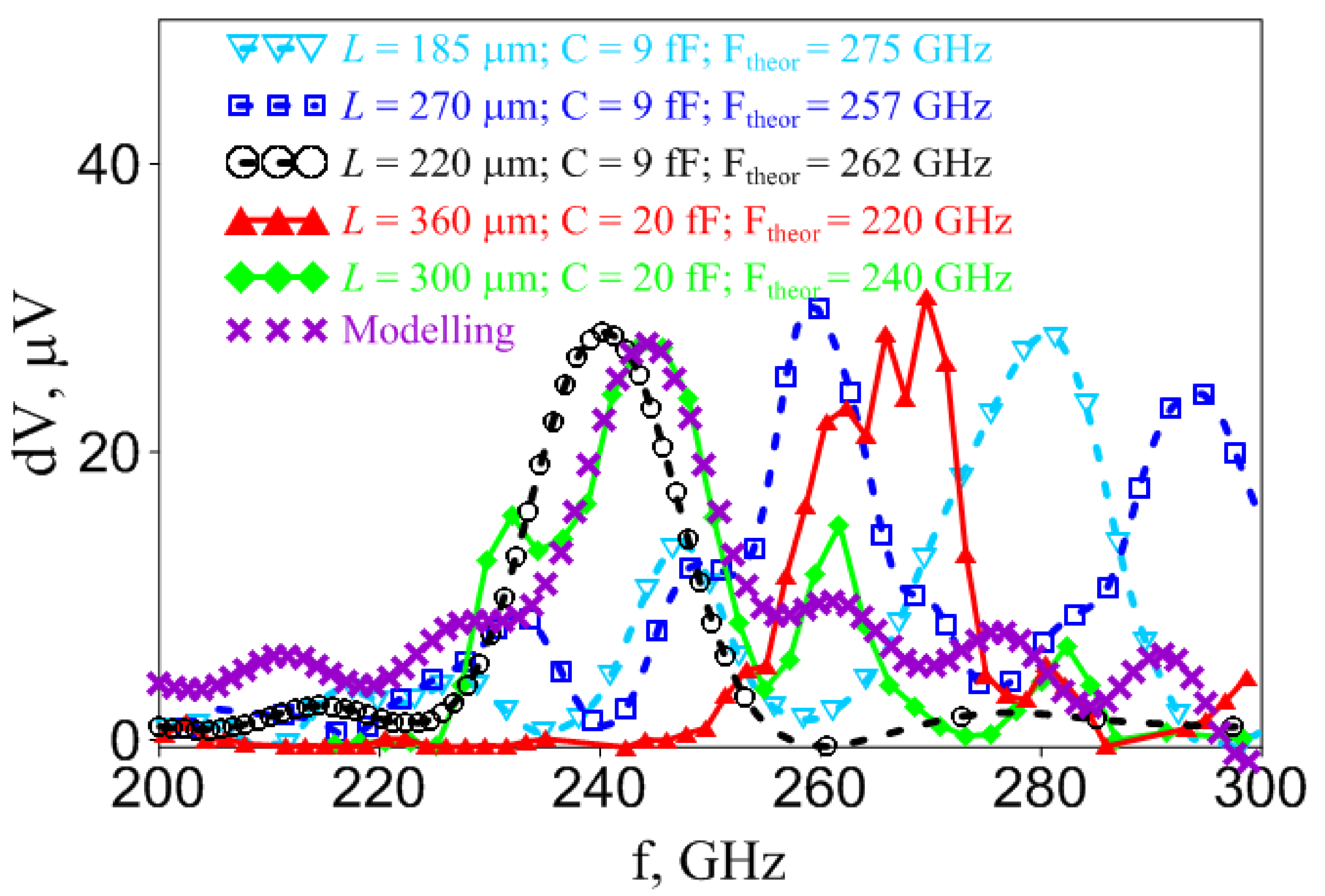
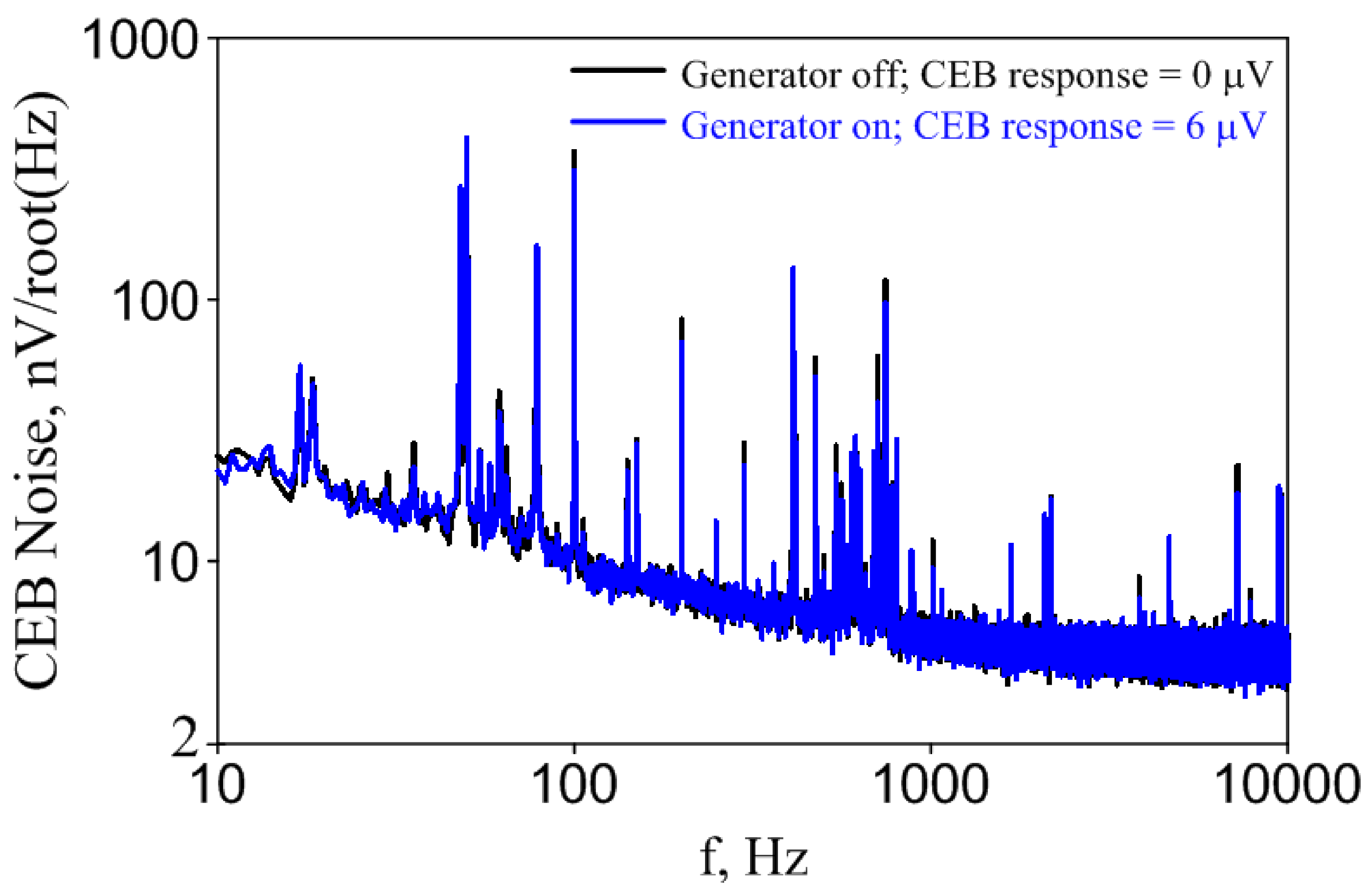
4. Measurement Results

Figure 4 presents the results of an experimental study of the resonant properties of CEBs with a double-folded slot antenna and coplanar lines. To develop a resonant receiving system at given frequencies, it is necessary to adjust the elements of the system, in particular, the capacity of the SIN junction in CEB and the length L = 2 · (L1 + L2 + L3) of the central coplanar line (see Figure 1). During the experiments, the effect of changes in these system parameters on the operating frequency was tested (Figure 4). We have also analyzed various designs of coplanar lines with rectangular turns as in Figure 3 (solid curves) and with rounded turns (dashed curves). It can be seen that by selecting the capacitance and lengths of the coplanar lines, the system can be tuned to the specified frequency range. It is seen that all characteristics have a clearly defined peak at different frequencies with a bandwidth of around 15 GHz. So, the resulting bandwidth of 6–9% practically meets the requirements for the LSPE experiment receiving system. Out of band peaks can be attributed both to peaks of YBCO amplitude-frequency characteristic and to the methodic of CEB sample irradiation. Due to the necessity to test the first on-chip filter prototypes we have placed up to 6 samples with various antennas on one chip and certain receivers are shifted from the chip center and standing waves differently affect various antennas. These issues will be corrected in future designs of both YBCO sources with more suitable broadband antennas and new designs of CEBs with on-chip filters with only one antenna at the chip center. Nevertheless, our experimental setup where the generator lens was mounted close to the receiver lens separated by infrared filters, allowed significantly reducing spurious resonances, which inevitably arose in experiments with room temperature sources of GHz radiation outside the cryostat [15] due to additional reflections from cryostat shields and much larger power.
The experimental center frequencies are in some cases shifted from the calculated values (see Figure 4, calculated center frequencies are given in the legend). This difference is most probably caused by the influence of the standing waves in a substrate, which were not taken into account in the initial simulations. Another possible reason for the frequency shift, found when designing the system [7], was the effect of dc wires, which will be precisely calculated in future designs. However, the most critical reason for the frequency shift is the fact that at low capacitance of the order of 10 fF, a small increase in capacitance due to overexposure of a tunnel junction may significantly shift the resonance to lower frequencies. Besides, at frequencies of several hundred GHz and at low temperatures it may be necessary to take into account the surface impedance of gold, which differs from the one at low frequencies and room temperature, and is known to be frequency-dependent. Also, as follows from the experimental results, the samples with rectangular coplanar lines demonstrate a stronger effect of standing waves leading to sharper satellite spikes. The simulation results, taking into account reflections from the substrate edges, are shown by crosses for the parameters close to the experiment for green solid curve with diamonds and qualitative agreement with the experiment is observed. Finally, among all the data we have found a sample (black dashed curve), which has a smooth shape and is centered exactly at the required 240 GHz. These sample parameters will be scaled in future designs to form a pair of antennas for 220/240 GHz channel of LSPE.
Figure 5 presents the comparison of CEB output voltage noise in the absence and in the presence of YBCO GHz signal. It can be seen that the noise level does not change due to rather weak external signal power (on the order of 1 pW, which was got from fitting as in [23]), received by the CEB, and narrow spectral linewidth of YBCO oscillator, operating at 4 K temperature. The total voltage noise of a bolometer δVtot consists of three components: the noise of the amplifier δVamp, the noise of the bolometer itself δVCEB and the noise of an external signal δVex, thus δVtot2 = δVamp2 + δVCEB2 + δVex2. Measured total noise (pedestal level) in the absence of an external signal at the frequency of 120 Hz is 8.5 nV/sqrt(Hz) (see Figure 5). Taking into account that the amplifier noise δVamp = 5 nV/sqrt(Hz), this means that the intrinsic noise of the bolometer δVCEB = 6.9 nV/sqrt(Hz) is slightly larger than the amplifier noise δVamp. When an external high-frequency signal is applied, the total noise of the bolometer may increase due to the amplitude and phase noise of the external generator (as it was in our experiments with the backward wave oscillator [15]) or due to photon noise δVph. The absence of changes in our case, Figure 5, indicates high stability of the source based on the high-temperature YBCO Josephson junction. On the other hand, we also do not observe the contribution of photon noise. It was shown [23] that for a power load of 5 pW the total noise-equivalent power of a single CEB with room temperature amplifiers AD745 equals 10−16 W/sqrt(Hz) and is larger than photon NEP. That is why we did not see noise growth in our experiments.
Finally, on the basis of this single cell, we are developing an array of resonant CEBs which are able to work in the photon noise limited regime for larger signal powers. Such regime was demonstrated in our previous works [7,8] for parallel-series arrays of cold-electron bolometers [26].

5. Multi-Cell Double-Folded Slot Antenna with Coplanar Lines and CEBs for Ancillary Frequency Channels of LSPE

In this section, we consider rounded arrays of double-folded slot antenna cells with resonant cold-electron bolometers for secondary frequency channels of SWIPE instrument, designed for the LSPE project. These frequency channels are set to 220 and 240 GHz with the required bandwidths around 5% for both channels and intended for receiving signals from a horn.
It is quite a challenging task to create such a narrowband array of antenna cells for so high frequency. While there are works on antenna metasurfaces [27,28,29,30,31,32,33], normally the resulting bandwidths are much above 10%. In difference with standard metasurfaces, where the signal from all antennas is fed to a single receiver, due to the small size of CEBs of order 1 um, it is possible to place the bolometer inside each antenna in the array, so we deal with the antenna array with distributed receivers. Here we show that certain progress in narrowband arrays is possible with double-folded slot cells, where a coplanar line is used for better impedance matching.
Previously, similar design of a current-biased array of double-slot cells with coplanar lines showed rather good results for creating a narrowband amplitude-frequency characteristic, as shown in simulations [20]. Now these antenna cells, grouped into rounded array, are connected in parallel with DC wires to work in a voltage-biased mode. DC wires are connected to coplanar lines, and they are put under the ground plane, so the construction requires an insulating layer between DC wires and the ground plane. For this design, the insulator is SiO2, while DC wires are made of gold.
Totally, there are three technological stages. The first one is for golden DC connection lines under cells ground planes. The second one creates insulation for these lines, providing no connection between DC wires and ground planes. At the third stage, we make ground planes with double-slot design and coplanar lines. Major DC connection wires are also created at this stage. A quarter of the rounded array used for calculations is shown in Figure 6.
The diameter of this rounded array should not exceed 4.5 mm. It is because of a predefined configuration of a back-to-back feedhorn, which will be used with this system. The optimal antenna cells number to fill this feedhorn configuration is 112.
The feedhorn is located on the opposite side of the substrate. In the numerical modeling, the feedhorn is simulated by a waveguide port as a source of radiation. Here we work only with the mode E01.
Calculation of such quite a large array will require a lot of computational resources, so we use symmetry planes to decrease the calculation time. For the mode E01 it is electric (Et = 0) symmetry plane at YZ plane and magnetic (Ht = 0) symmetry plane at XZ plane. Due to this, we have to perform calculations for 28 antenna cells and the mesh cells number is about 3.5 million only. Without symmetry planes, these numbers would have increased by a factor of four.
Figure 7 shows the accepted power versus frequency curves for all CEBs of the array at 220 and 240 GHz frequency channels, respectively. The bandwidth for the 220 GHz channel at half of the accepted power is about 18 GHz or 8.2%, from 210 to 228 GHz. It is quite close to meet the requirements for LSPE. The deviation from the required bandwidth is mostly at the lower frequencies, so to decrease the bandwidth an additional external filter can be used. The 240 GHz channel bandwidth is very close to meet LSPE project requirements. At half of the accepted power, the bandwidth is about 14 GHz or 5.8%, from 232.5 to 246.5 GHz. The absorption efficiency of the array has reached 81% and 77% for 220 and 240 GHz channels, respectively. The work on optimization of frequency response for 220 and 240 GHz channels is being continued.

6. Discussion

A prototype of a single detecting cell in the form of a double-folded slot narrow-band antenna for the LSPE experiment has been developed. During this stage, technological issues of fabrication of these antennas were investigated, the influence of the length of coplanar lines and capacitances of SIN junctions on the operating frequency of the receiving system was checked. This allowed selecting a double-folded slot receiving system with the coplanar line, having smooth amplitude-frequency characteristic centered at 240 GHz, which can be used for further design of double frequency 220/240 GHz receiver for LSPE mission. Based on these results, 2-D array of double-folded slot antennas with CEBs as 220/240 GHz LSPE channel prototype was calculated.
A double-folded slot antenna with coplanar lines represents a type of planar antenna, which is suitable for cosmology projects due to its compactness, flexibility of adjustment, and ease of fabrication. This antenna can be used for a wide range of tasks with multi-frequency systems.

Author Contributions

Conceptualization—L.S.K., S.M. and P.d.B.; Methodology—L.S.K., S.M., P.d.B. and A.L.P.; Formal analysis—L.S.K., A.L.P., L.S.R. and A.V.G.; Investigation—L.S.R., D.A.P., A.V.B., A.V.G., A.L.P., A.V.C., I.V.R. and V.O.Z.; Data curation—L.S.R., D.A.P., A.V.B., A.V.G. and A.L.P.; Writing—original draft preparation—L.S.R., D.A.P., A.V.G., A.L.P. and A.V.C.; Writing—review and editing—L.S.K., A.L.P., S.M. and P.d.B.; Supervision—L.S.K. and A.L.P.; Project administration—A.L.P.; Funding acquisition—A.L.P. All authors have read and agreed to the published version of the manuscript.

Funding

This work was supported by the Center of Excellence «Center of Photonics» funded by The Ministry of Science and Higher Education of the Russian Federation, contract № 075-15-2020-906.

Institutional Review Board Statement

Not applicable.

Informed Consent Statement

Not applicable.

Data Availability Statement

The data that support the findings of this work are available from the corresponding author upon reasonable request.

Conflicts of Interest

The authors declare no conflict of interest. The funders had no role in the design of the study; in the collection, analyses, or interpretation of data; in the writing of the manuscript, or in the decision to publish the results.

References

  1. Aiola, S.; Amico, G.; Battaglia, P.; Battistelli, E.; Baù, A.; de Bernardis, P.; Bersanelli, M.; Boscaleri, A.; Cavaliere, F.; Coppolecchia, A.; et al. The Large-Scale Polarization Explorer (LSPE). Proc. SPIE 2012, 8446, 84467A. [Google Scholar] [CrossRef] [Green Version]
  2. Planck, C.; Adam, R.; Ade, P.; Aghanim, N.; Arnaud, M.; Aumont, J.; Baccigalupi, C.; Banday, A.J.; Barreiro, R.B.; Bartlett, J.G.; et al. Planck intermediate results. XXX. The angular power spectrum of polarized dust emission at intermediate and high Galactic latitudes. Astron. Astrophys. 2016, 586, A133. [Google Scholar] [CrossRef] [Green Version]
  3. Kuzmin, L. Optimization of the Hot-Electron Bolometer and A Cascade Quasiparticle Amplifier for Space Astronomy. In International Workshop on Superconducting Nano-Electronics Devices; Pekola, J., Ruggiero, B., Silvestrini, P., Eds.; Springer Science and Business Media LLC: Boston, MA, USA, 2002; pp. 145–154. [Google Scholar] [CrossRef] [Green Version]
  4. Kuzmin, L. An array of cold-electron bolometers with SIN tunnel junctions and JFET readout for cosmology instruments. J. Phys. Conf. Ser. 2008, 97, 012310. [Google Scholar] [CrossRef] [Green Version]
  5. Tarasov, M.; Kuzmin, L.S.; Edelman, V.S.; Mahashabde, S.; de Bernardis, P. Optical Response of a Cold-Electron Bolometer Array Integrated in a 345-GHz Cross-Slot Antenna. IEEE Trans. Appl. Supercond. 2011, 21, 3635–3639. [Google Scholar] [CrossRef]
  6. Gordeeva, A.V.; Pankratov, A.L.; Pugach, N.G.; Vasenko, A.S.; Zbrozhek, V.O.; Blagodatkin, A.V.; Pimanov, D.A.; Kuzmin, L.S. Record electron self-cooling in cold-electron bolometers with a hybrid superconductor-ferromagnetic nanoabsorber and traps. Sci. Rep. 2020, 10, 21961. [Google Scholar] [CrossRef]
  7. Kuzmin, L.S.; Pankratov, A.L.; Gordeeva, A.V.; Zbrozhek, V.O.; Shamporov, V.A.; Revin, L.S.; Blagodatkin, A.V.; Masi, S.; De Bernardis, P. Photon-noise-limited cold-electron bolometer based on strong electron self-cooling for high-performance cosmology missions. Commun. Phys. 2019, 2, 104. [Google Scholar] [CrossRef] [Green Version]
  8. Gordeeva, A.V.; Zbrozhek, V.O.; Pankratov, A.L.; Revin, L.S.; Shamporov, V.A.; Gunbina, A.A.; Kuzmin, L.S. Observation of photon noise by cold-electron bolometers. Appl. Phys. Lett. 2017, 110, 162603. [Google Scholar] [CrossRef] [Green Version]
  9. Salatino, M.; de Bernardis, P.; Kuzmin, L.S.; Mahashabde, S.; Masi, S. Sensitivity to Cosmic Rays of Cold Electron Bolometers for Space Applications. J. Low Temp. Phys. 2014, 176, 323–328. [Google Scholar] [CrossRef] [Green Version]
  10. Kuzmin, L.S. A Resonant Cold-Electron Bolometer with a Kinetic Inductance Nanofilter. IEEE Trans. Terahertz Sci. Technol. 2014, 4, 314–320. [Google Scholar] [CrossRef]
  11. Kuzmin, L.S.; Chiginev, A.V.; Matrozova, E.A.; Sobolev, A.S. Multifrequency Seashell Slot Antenna with Cold-Electron Bolometers for Cosmology Space Missions. IEEE Trans. Appl. Supercond. 2016, 26, 2300206. [Google Scholar] [CrossRef]
  12. Kuzmin, L.S.; Chiginev, A.V. Multichroic bandpass seashell antenna with cold-electron bolometers for CMB measurements. Proc. SPIE 2016, 9914, 99141. [Google Scholar] [CrossRef] [Green Version]
  13. Filipovic, D.F.; Gearhart, S.S.; Rebeiz, G.M. Double-slot antennas on extended hemispherical and elliptical silicon die-lectric lenses. IEEE-MTT 1993, 41, 1738. [Google Scholar] [CrossRef]
  14. Gaidis, M.; LeDuc, H.; Bin, M.; Miller, D.; Stern, J.; Zmuidzinas, J. Characterization of low-noise quasi-optical SIS mixers for the submillimeter band. IEEE-MTT 1996, 44, 1130–1139. [Google Scholar] [CrossRef]
  15. Kuzmin, L.S.; Blagodatkin, A.V.; Mukhin, A.S.; Pimanov, D.; O Zbrozhek, V.; Gordeeva, A.V.; Pankratov, A.L.; Chiginev, A.V. Multichroic seashell antenna with internal filters by resonant slots and cold-electron bolometers. Supercond. Sci. Technol. 2019, 32, 035009. [Google Scholar] [CrossRef]
  16. Mukhin, A.S.; Kuzmin, L.S.; Chiginev, A.; Blagodatkin, A.V.; Zbrozhek, V.O.; Gordeeva, A.V.; Pankratov, A.L. Multifrequency seashell antenna based on resonant cold-electron bolometers with kinetic Inductance Nanofilters for CMB measurements. AIP Adv. 2019, 9, 015321. [Google Scholar] [CrossRef] [Green Version]
  17. Trappe, N.; Bucher, M.; De Bernardis, P.; Delabrouille, J.; Deo, P.; Depetris, M.; Doherty, S.; Ghribi, A.; Gradziel, M.; Kuzmin, L.; et al. Next generation sub-millimeter wave focal plane array coupling concepts: An ESA TRP project to develop multichroic focal plane pixels for future CMB polarization experiments. Proc. SPIE 2016, 9914, 991412. [Google Scholar]
  18. Weller, T.; Katehi, L.; Rebeiz, G. Single and double folded-slot antennas on semi-infinite substrates. IEEE Trans. Antennas Propag. 1995, 43, 1423–1428. [Google Scholar] [CrossRef]
  19. Gauthier, G.; Rebeiz, G.; Raman, S. A 90-100 GHz double-folded slot antenna. IEEE Trans. Antennas Propag. 1999, 47, 1120–1122. [Google Scholar] [CrossRef]
  20. Kuzmin, L.S.; Pimanov, D.; Gordeeva, A.V.; Chiginev, A.V.; Masi, S.; De Bernardis, P. A dual-band cold-electron bolometer with on-chip filters for the 220/240 GHz channels of the LSPE instrument. Supercond. Sci. Technol. 2019, 32, 084005. [Google Scholar] [CrossRef] [Green Version]
  21. Stepantsov, E.; Tarasov, M.; Kalabukhov, A.; Kuzmin, L.S.; Claeson, T. THz Josephson properties of grain boundary YBaCuO junctions on symmetric, tilted bicrystal sapphire substrates. J. Appl. Phys. 2004, 96, 3357–3361. [Google Scholar] [CrossRef] [Green Version]
  22. Revin, L.S.; Pimanov, D.; Blagodatkin, A.V.; Gordeeva, A.V.; Zbrozhek, V.; Masterov, D.V.; Parafin, A.E.; Pavlov, S.A.; Pankratov, A.L.; Rakut’, I.V.; et al. Investigation of the narrow-band receiving system of Cold Electrons Bolometers for channels 220/240 GHz by HTSC YBCO generator. Radiophys. Quantum Electron. 2019, 62, 556–561. [Google Scholar] [CrossRef]
  23. Revin, L.; Pankratov, A.; Gordeeva, A.; Masterov, D.; Parafin, A.; Zbrozhek, V.; Kuzmin, L. Response of a Cold-Electron Bolometer on THz Radiation from a Long YBa2Cu3O7-δBicrystal Josephson Junction. Appl. Sci. 2020, 10, 7667. [Google Scholar] [CrossRef]
  24. Masterov, D.V.; E Parafin, A.; Revin, L.S.; Chiginev, A.; Skorokhodov, E.V.; A Yunin, P.; Pankratov, A.L. YBa2Cu3O7−δ long Josephson junctions on bicrystal Zr1−xYxO2 substrates fabricated by preliminary topology masks. Supercond. Sci. Technol. 2017, 30, 025007. [Google Scholar] [CrossRef]
  25. Revin, L.S.; Pankratov, A.L.; Masterov, D.V.; Parafin, A.E.; Pavlov, S.A.; Chiginev, A.V.; Skorokhodov, E.V. Features of Long YBCO Josephson Junctions Fabricated by Preliminary Topology Mask. IEEE Trans. Appl. Supercond. 2018, 28, 1100505. [Google Scholar] [CrossRef]
  26. Kuzmin, L. A Parallel/Series Array of Cold-Electron Bolometers with SIN Tunnel Junctions for Cosmology Instruments. IEEE/CSC ESAS Eur. Supercond. News Forum 2008, 3, 1–9. [Google Scholar]
  27. Alibakhshikenari, M.; Virdee, B.S.; Althuwayb, A.A.; Aïssa, S.; See, C.H.; Abd-Alhameed, R.A.; Falcone, F.; Limiti, E. Study on on-Chip Antenna Design Based on Metamaterial-Inspired and Substrate-Integrated Waveguide Properties for Millimetre-Wave and THz Integrated-Circuit Applications. J. Infrared Millim. Terahertz Waves 2021, 42, 17–28. [Google Scholar] [CrossRef]
  28. Althuwayb, A.A. On-Chip Antenna Design Using the Concepts of Metamaterial and SIW Principles Applicable to Terahertz Integrated Circuits Operating over 0.6–0.622 THz. Int. J. Antennas Propag. 2020, 2020, 6653095. [Google Scholar] [CrossRef]
  29. Beiranvand, B.; Sobolev, A.; Larionov, M.; Kuzmin, L. A Distributed Terahertz Metasurface with Cold-Electron Bolometers for Cosmology Missions. Appl. Sci. 2021, 11, 4459. [Google Scholar] [CrossRef]
  30. Alibakhshikenari, M.; Virdee, B.S.; Khalily, M.; See, C.H.; Abd-Alhameed, R.; Falcone, F.; Denidni, T.A.; Limiti, E. High-Gain On-Chip Antenna Design on Silicon Layer with Aperture Excitation for Terahertz Applications. IEEE Antennas Wirel. Propag. Lett. 2020, 19, 1576–1580. [Google Scholar] [CrossRef]
  31. Alibakhshikenari, M.; Virdee, B.S.; See, C.H.; Shukla, P.; Salekzamankhani, S.; Abd-Alhameed, R.A.; Falcone, F.; Limiti, E. Study on improvement of the performance parameters of a novel 0.41–0.47 THz on-chip antenna based on metasurface concept realized on 50 μm GaAs-layer. Sci. Rep. 2020, 10, 11034. [Google Scholar] [CrossRef] [PubMed]
  32. Alibakhshikenari, M.; Virdee, B.S.; See, C.H.; Abd-Alhameed, R.A.; Falcone, F.; Limiti, E. High-Gain Metasurface in Polyimide On-Chip Antenna Based on CRLH-TL for Sub-Terahertz Integrated Circuits. Sci. Rep. 2020, 10, 4298. [Google Scholar] [CrossRef] [PubMed] [Green Version]
  33. Kuzmin, L.S.; Sobolev, A.S.; Beiranvand, B. Wideband Double-Polarized Array of Cold-Electron Bolometers for OLIMPO Balloon Telescope. IEEE Trans. Antennas Propag. 2021, 69, 1427–1432. [Google Scholar] [CrossRef]
Figure 1. (a) Double-slot antenna single cell design: 1—slots; 2—receiving port cold-electron bolometers (CEB); 3—metal layer. Here the slot length is 162 um and the length of the coplanar line is L = 2 · (L1 + L2 + L3), and is equal to 360 um, which corresponds to the sample photo in Figure 3. (b) CEB connected to a double-slot antenna, equivalent circuit.
Applsci 11 10746 g001
Figure 2. SEM image of fabricated CEB integrated into the double-folded slot antenna. Short red arrows show the electric field distribution in the slot and in the coplanar waveguide (CPW).
Applsci 11 10746 g002
Figure 3. The experimental setup view, its schematic representation, and samples design.
Applsci 11 10746 g003
Figure 4. The amplitude-frequency characteristics of cold-electron bolometers with different capacitance C and lengths L of coplanar lines. Solid curves—rectangular coplanars, dashed curves—rounded coplanars, crosses—theory for the parameters close to the experiment for green solid curve with diamonds.
Applsci 11 10746 g004
Figure 5. Voltage noise of CEB under the influence of YBaCuO signal and in the absence of external GHz radiation.
Applsci 11 10746 g005
Figure 6. A quarter of the antenna cells array, used for numerical modelling with symmetry planes. Blue circle shows the 4.5 mm waveguide feedhorn opening.
Applsci 11 10746 g006
Figure 7. Frequency response curves of the receiving system for LSPE ancillary channels 220 GHz (blue curve) and 240 GHz (red curve).
Applsci 11 10746 g007
Publisher’s Note: MDPI stays neutral with regard to jurisdictional claims in published maps and institutional affiliations.

