
Biomechanical Evaluation of Cortical Bone Trajectory Fixation with Traditional Pedicle Screw in the Lumbar Spine: A Finite Element Study


Abstract
:1. Introduction
2. Materials and Methods
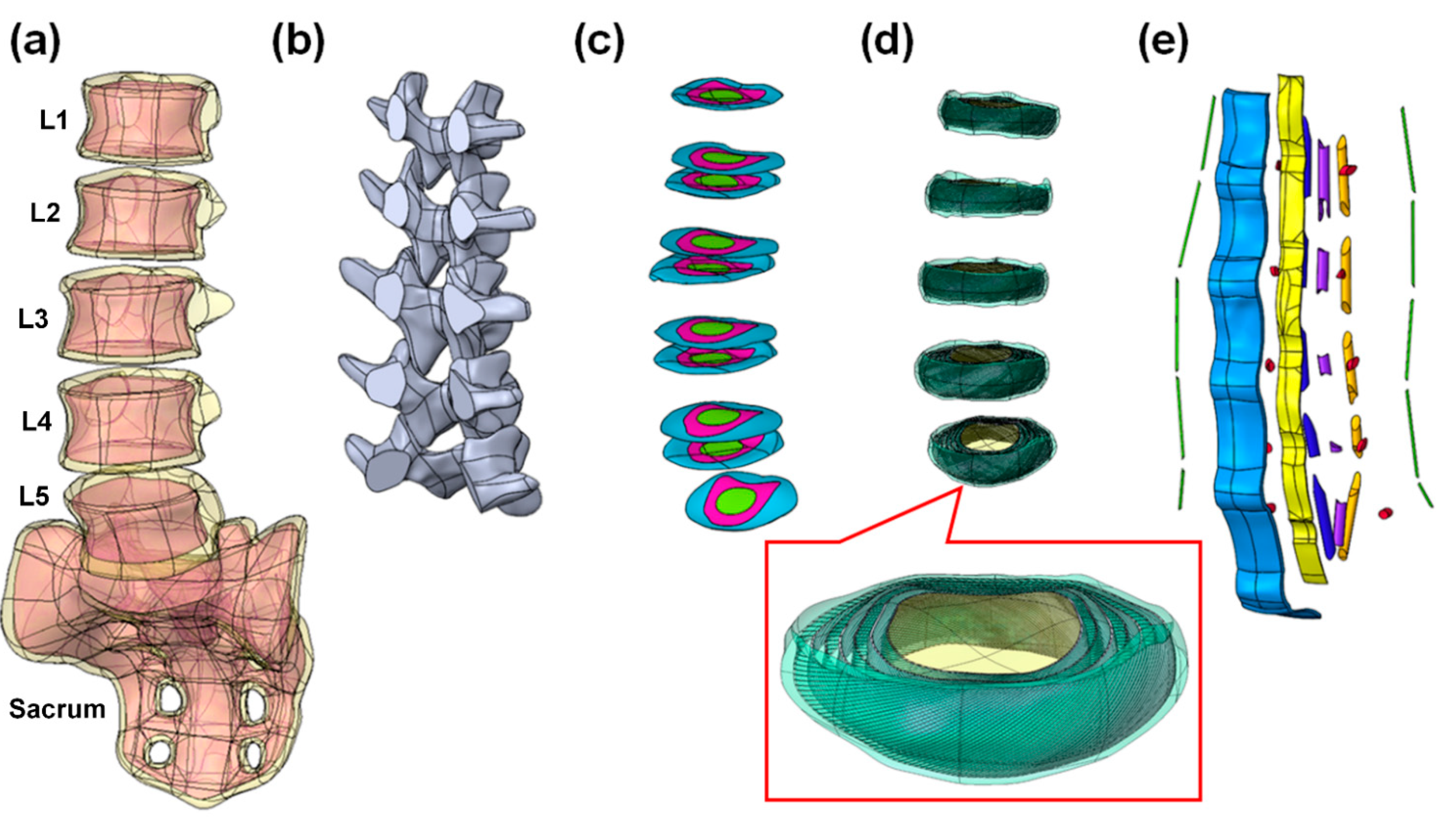
2.1. Simulation of Lumbar Geometry Model
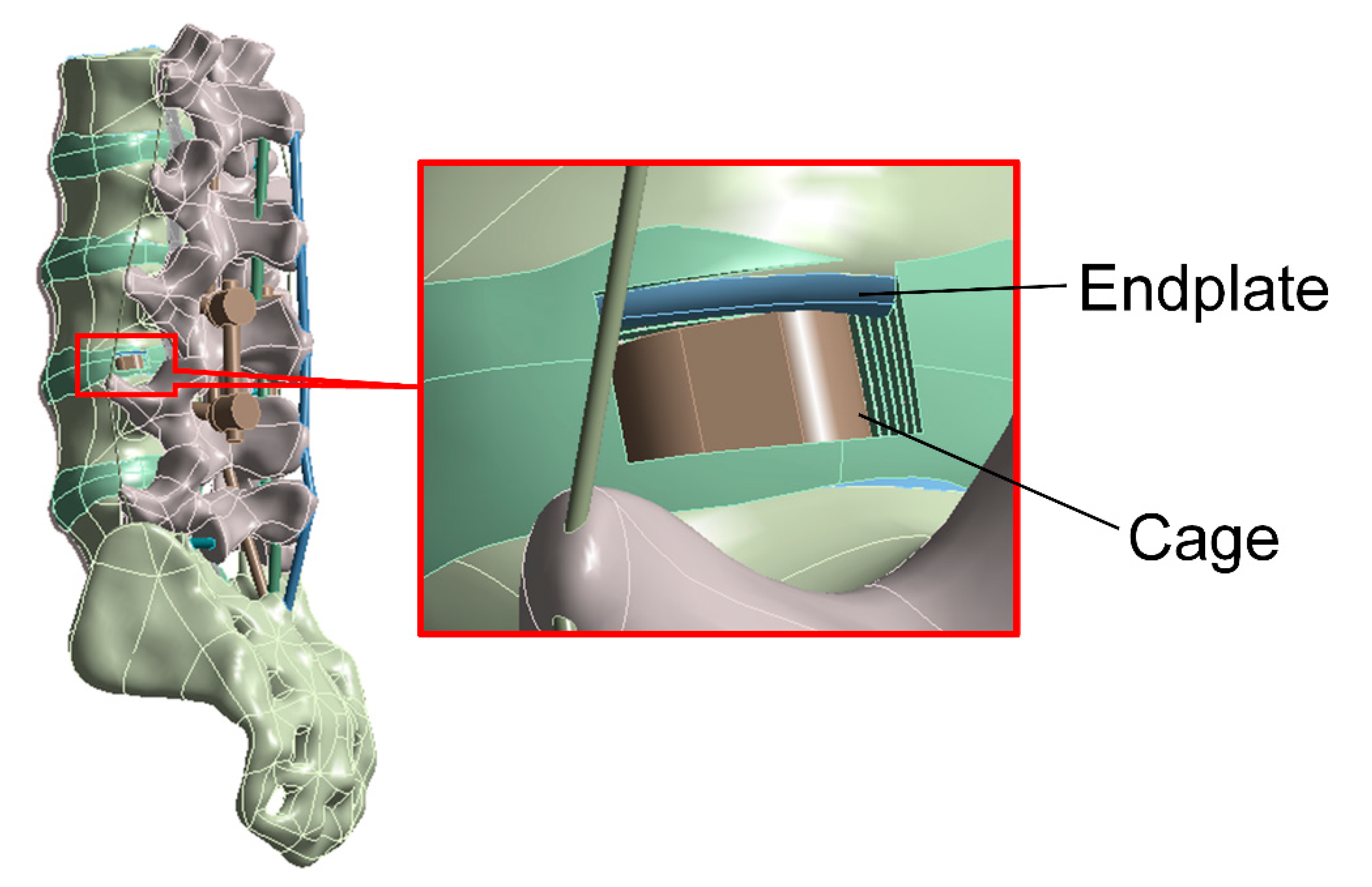
2.2. Traditional Pedicle Screw System and Cortical Bone Trajectory System
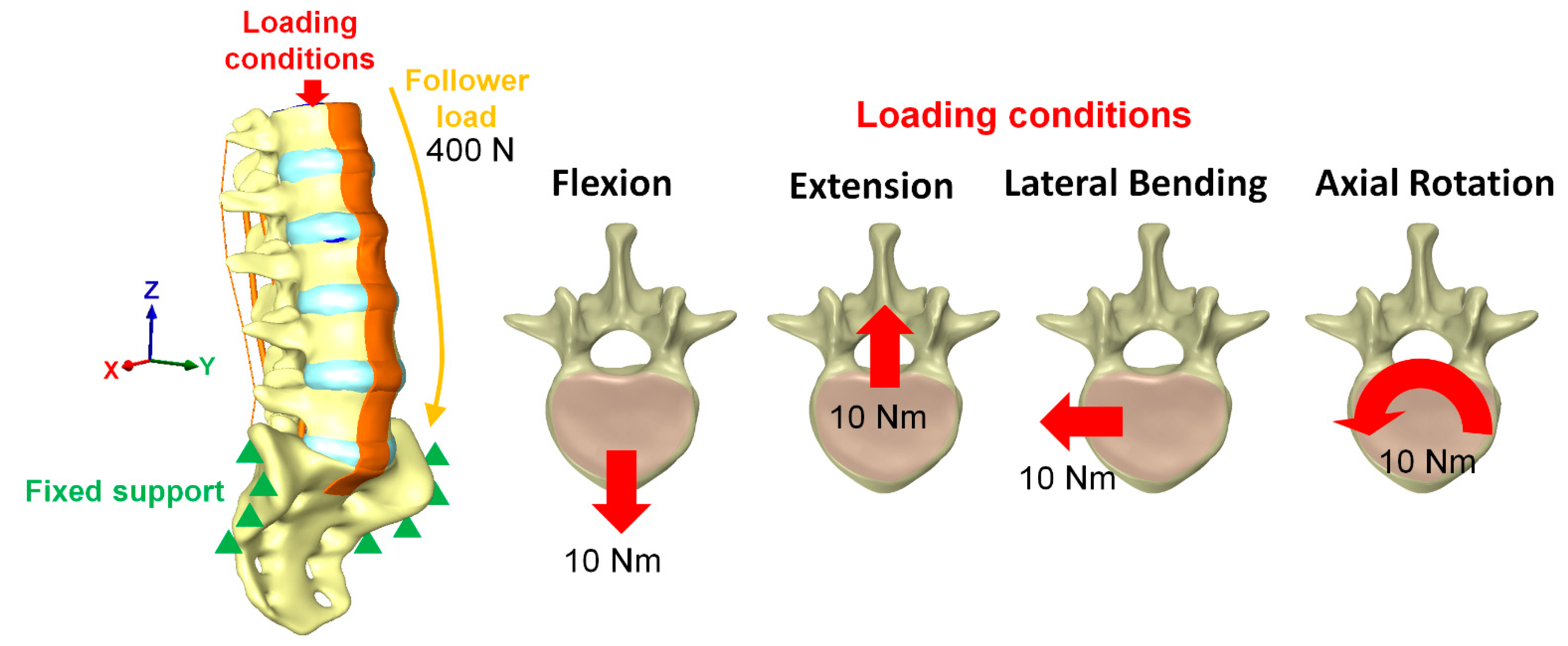
2.3. Loading Conditions and Boundary Conditions
2.4. Material Properties of the Model
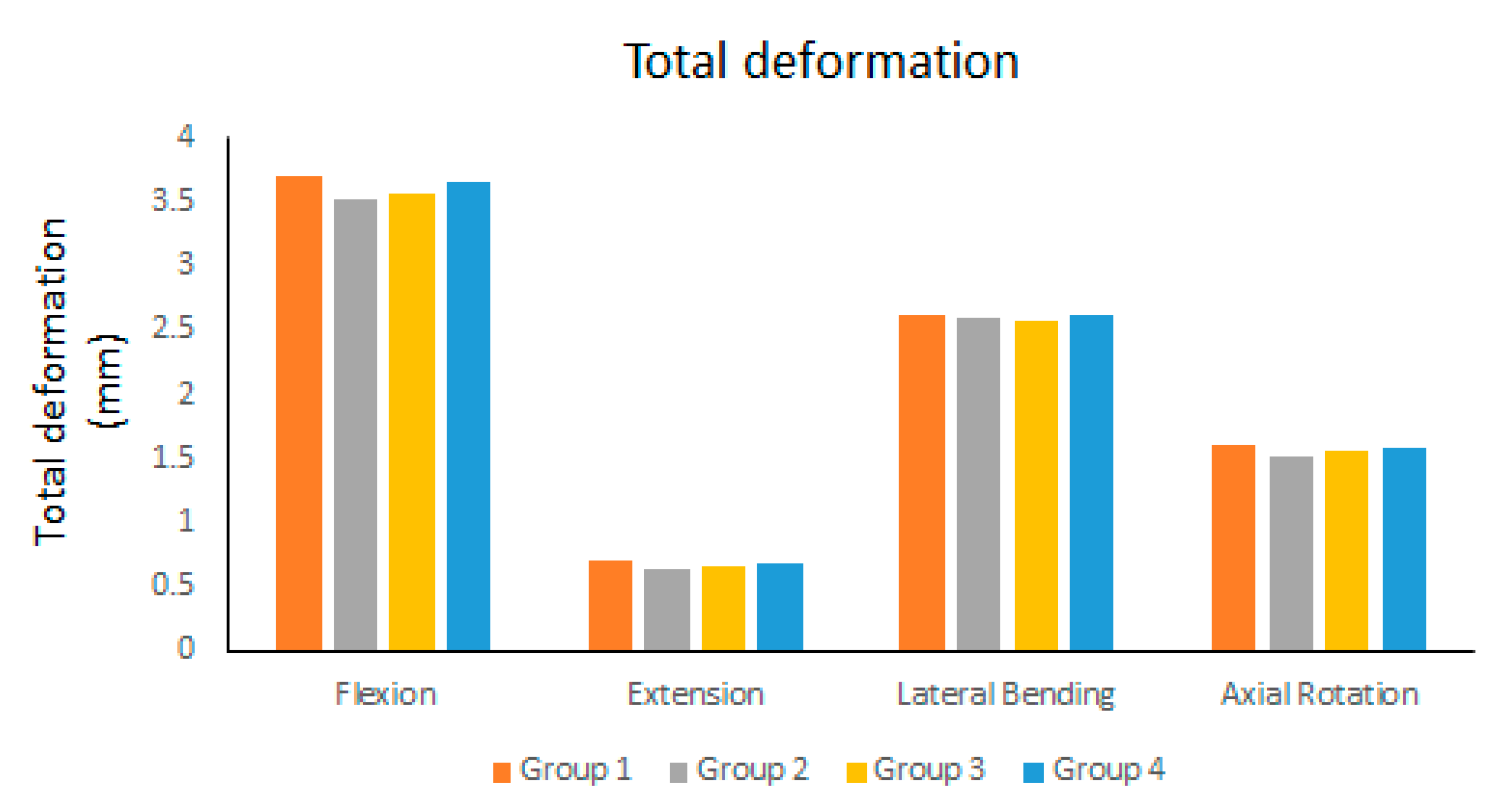
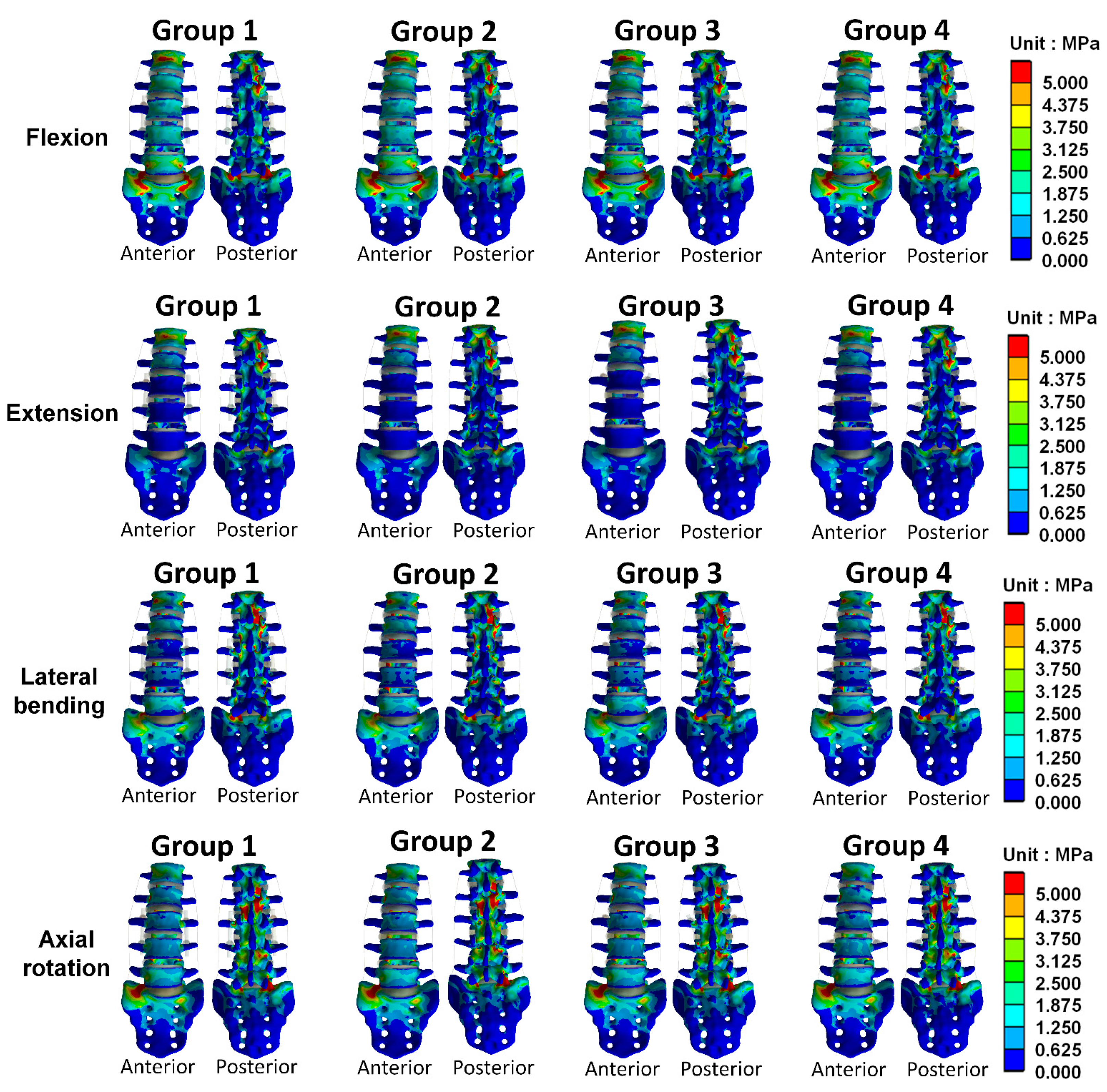
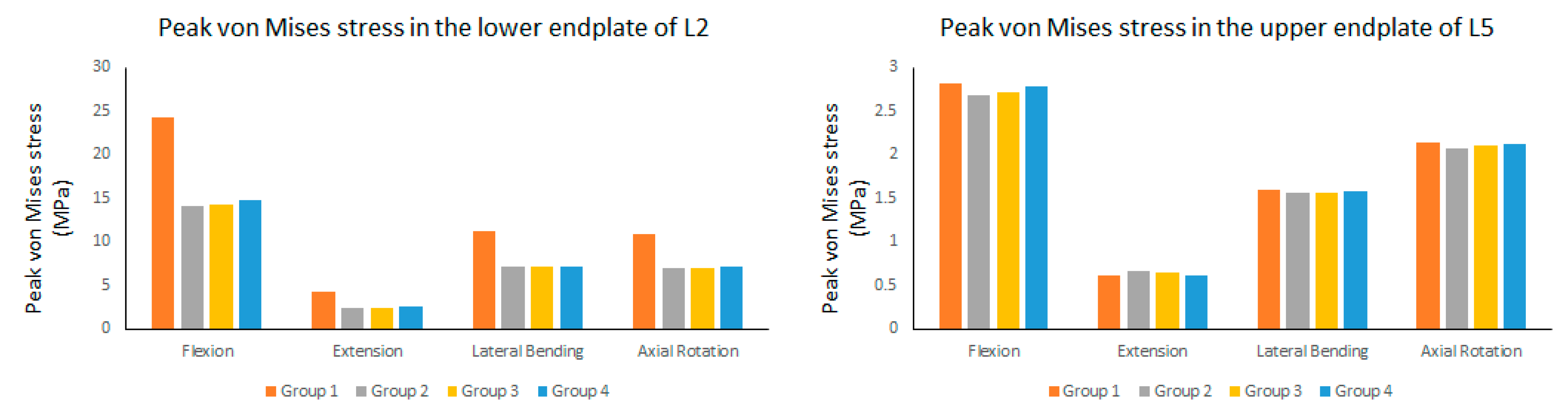
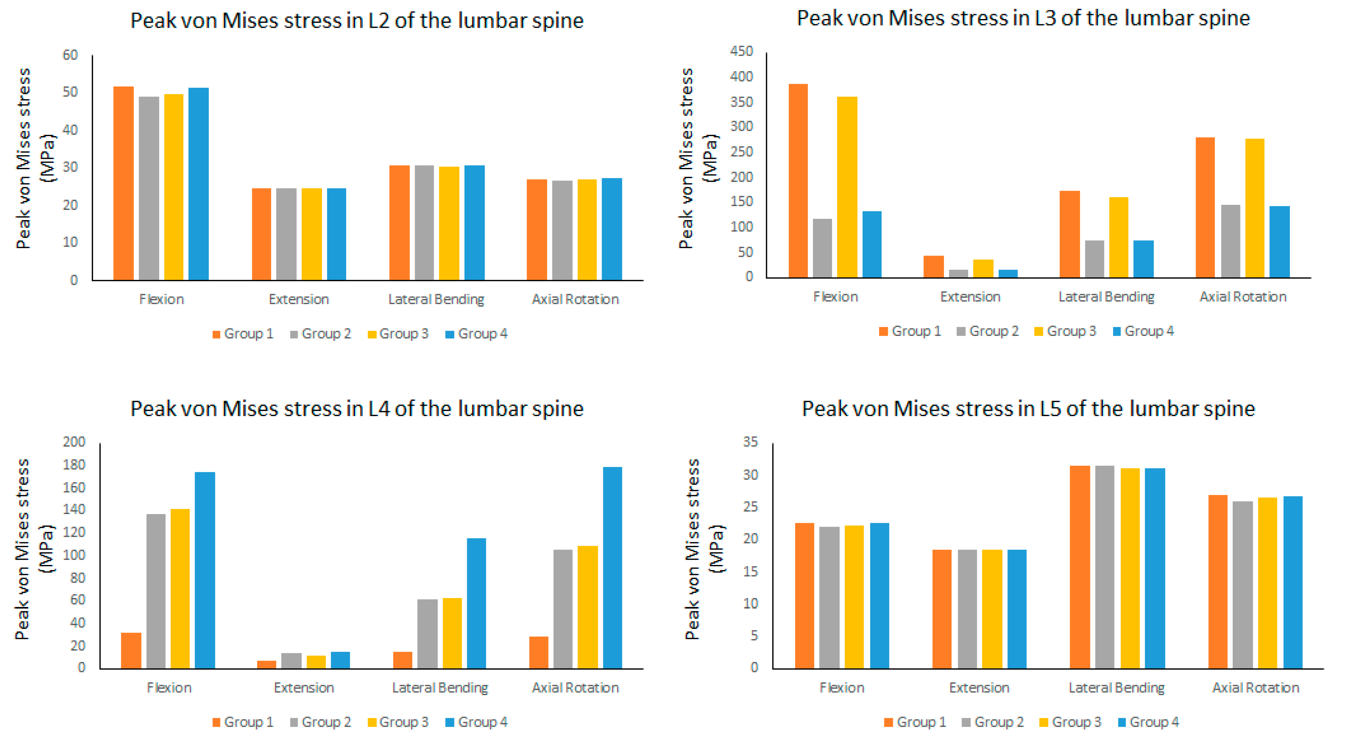
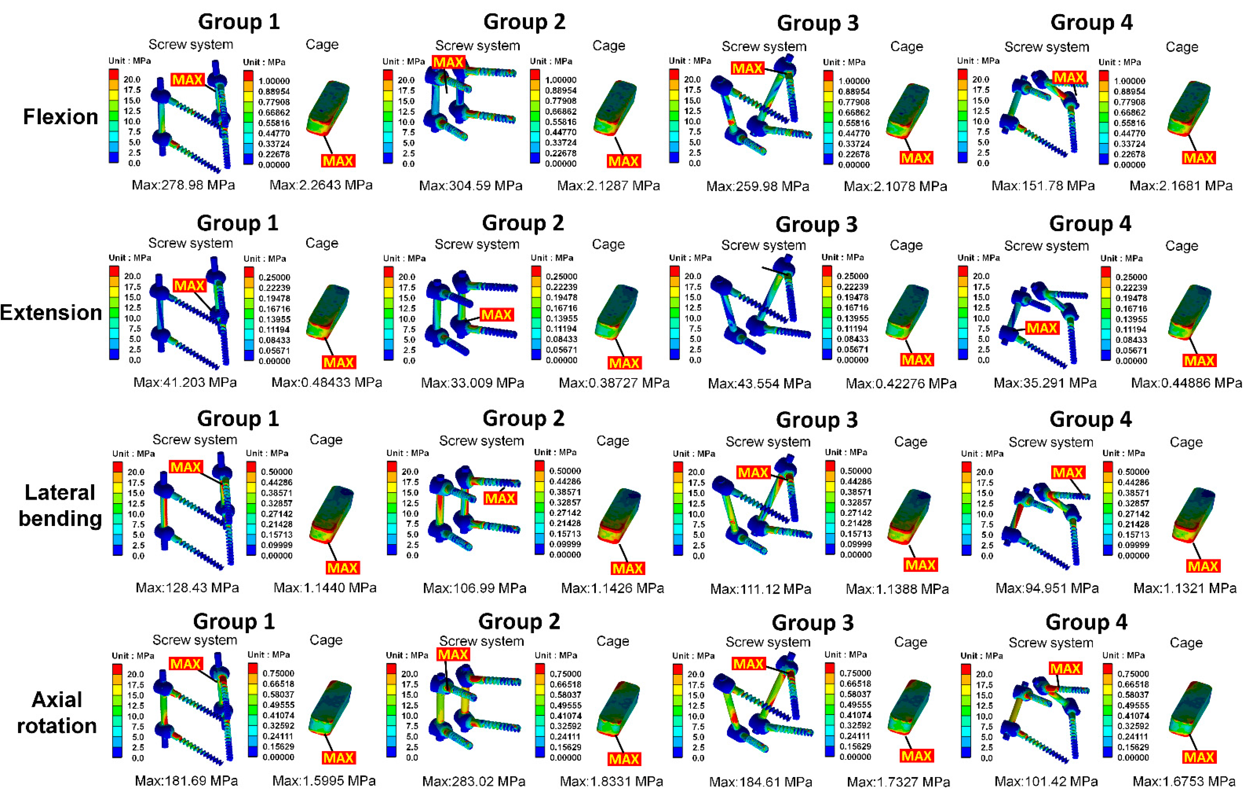
3. Results
4. Discussion
5. Conclusions
Author Contributions
Funding
Institutional Review Board Statement
Informed Consent Statement
Data Availability Statement
Acknowledgments
Conflicts of Interest
References
- Ponnusamy, K.E.; Iyer, S.; Gupta, G.; Khanna, A.J. Instrumentation of the osteoporotic spine: Biomechanical and clinical considerations. Spine J. 2011, 11, 54–63. [Google Scholar] [CrossRef] [PubMed]
- Park, P.; Garton, H.J.; Gala, V.C.; Hoff, J.T.; McGillicuddy, J.E. Adjacent Segment Disease after Lumbar or Lumbosacral Fusion: Review of the Literature. Spine 2004, 29, 1938–1944. [Google Scholar] [CrossRef] [PubMed]
- Martin, B.I.; Mirza, S.K.; Comstock, B.A.; Gray, D.T.; Kreuter, W.; Deyo, R.A. Are Lumbar Spine Reoperation Rates Falling with Greater Use of Fusion Surgery and New Surgical Technology? Spine 2007, 32, 2119–2126. [Google Scholar] [CrossRef] [PubMed]
- Tobert, D.G.; Antoci, V.; Patel, S.; Saadat, E.; Bono, C.M. Adjacent Segment Disease in the Cervical and Lumbar Spine. Clin. Spine Surg. 2017, 30, 94–101. [Google Scholar] [CrossRef]
- Bederman, S.S.; Le, V.H.; Pahlavan, S. An Approach to Lumbar Revision Spine Surgery in Adults. J. Am. Acad. Orthop. Surg. 2016, 24, 433–442. [Google Scholar] [CrossRef] [Green Version]
- Dabbous, B.; Brown, D.; Tsitlakidis, A.; Arzoglou, V. Clinical outcomes during the learning curve of MIDline Lumbar Fusion (MIDLF®) using the cortical bone trajectory. Acta Neurochir. 2016, 158, 1413–1420. [Google Scholar] [CrossRef]
- Delgado-Fernandez, J.; García-Pallero, M.Á.; Blasco, G.; Pulido-Rivas, P.; Rafael, G.S. Review of Cortical Bone Trajectory: Evidence of a New Technique. Asian Spine J. 2017, 11, 817–831. [Google Scholar] [CrossRef] [Green Version]
- Santoni, B.; Hynes, R.; McGilvray, K.; Rodriguez-Canessa, G.; Lyons, A.; Henson, M.; Womack, W.; Puttlitz, C. Cortical bone trajectory for lumbar pedicle screws. Spine J. 2009, 9, 366–373. [Google Scholar] [CrossRef]
- Matsukawa, K.; Yato, Y.; Kato, T.; Imabayashi, H.; Asazuma, T.; Nemoto, K. Cortical bone trajectory for lumbosacral fixation: Penetrating S-1 endplate screw technique. J. Neurosurg. Spine 2014, 21, 203–209. [Google Scholar] [CrossRef] [Green Version]
- Chen, C.-H.; Huang, H.-M.; Chen, D.-C.; Wu, C.-Y.; Lee, H.-C.; Cho, D.-Y. Cortical bone trajectory screws fixation in lumbar adjacent segment disease: A technique note with case series. J. Clin. Neurosci. 2018, 48, 224–228. [Google Scholar] [CrossRef]
- Tortolani, P.J.; Stroh, D.A. Cortical Bone Trajectory Technique for Posterior Spinal Instrumentation. J. Am. Acad. Orthop. Surg. 2016, 24, 755–761. [Google Scholar] [CrossRef] [PubMed]
- Ueno, M.; Imura, T.; Inoue, G.; Takaso, M. Posterior corrective fusion using a double-trajectory technique (cortical bone trajectory combined with traditional trajectory) for degenerative lumbar scoliosis with osteoporosis. J. Neurosurg. Spine 2013, 19, 600–607. [Google Scholar] [CrossRef] [PubMed]
- Wang, J.; He, X.; Sun, T. Comparative clinical efficacy and safety of cortical bone trajectory screw fixation and traditional pedicle screw fixation in posterior lumbar fusion: A systematic review and meta-analysis. Eur. Spine J. 2019, 28, 1678–1689. [Google Scholar] [CrossRef] [PubMed]
- Matsukawa, K.; Yato, Y.; Imabayashi, H.; Hosogane, N.; Asazuma, T.; Nemoto, K. Biomechanical Evaluation of Cross Trajectory Technique for Pedicle Screw Insertion: Combined Use of Traditional Trajectory and Cortical Bone Trajectory. Orthop. Surg. 2015, 7, 317–323. [Google Scholar] [CrossRef] [Green Version]
- Matsukawa, K.; Yato, Y.; Imabayashi, H.; Hosogane, N.; Abe, Y.; Asazuma, T.; Chiba, K. Biomechanical evaluation of fixation strength among different sizes of pedicle screws using the cortical bone trajectory: What is the ideal screw size for optimal fixation? Acta Neurochir. 2016, 158, 465–471. [Google Scholar] [CrossRef] [PubMed]
- Liu, C.-W.; Wang, L.-L.; Xu, Y.-K.; Chen, C.-M.; Wang, J.-C.; Tsai, W.-T.; Lin, S.-C. Traditional and cortical trajectory screws of static and dynamic lumbar fixation-a finite element study. BMC Musculoskelet. Disord. 2020, 21, 463. [Google Scholar] [CrossRef] [PubMed]
- Zhang, L.; Li, H.-M.; Zhang, R.; Zhang, H.; Shen, C.-L. Biomechanical Changes of Adjacent and Fixed Segments through Cortical Bone Trajectory Screw Fixation versus Traditional Trajectory Screw Fixation in the Lumbar Spine: A Finite Element Analysis. World Neurosurg. 2021, 151, e447–e456. [Google Scholar] [CrossRef]
- Matsukawa, K.; Yato, Y.; Imabayashi, H.; Hosogane, N.; Asazuma, T.; Chiba, K. Biomechanical evaluation of lumbar pedicle screws in spondylolytic vertebrae: Comparison of fixation strength between the traditional trajectory and a cortical bone trajectory. J. Neurosurg. Spine 2016, 24, 910–915. [Google Scholar] [CrossRef] [Green Version]
- Wang, T.; Wu, B.; Duan, R.; Yuan, Y.; Qu, M.; Zhang, S.; Huang, W.; Liu, T.; Yu, X. Treatment of Thoracolumbar Fractures Through Different Short Segment Pedicle Screw Fixation Techniques: A Finite Element Analysis. Orthop. Surg. 2020, 12, 601–608. [Google Scholar] [CrossRef]
- Choi, K.-C.; Ryu, K.-S.; Lee, S.-H.; Kim, Y.H.; Lee, S.J.; Park, C.-K. Biomechanical comparison of anterior lumbar interbody fusion: Stand-alone interbody cage versus interbody cage with pedicle screw fixation—A finite element analysis. BMC Musculoskelet. Disord. 2013, 14, 220. [Google Scholar] [CrossRef] [Green Version]
- Erbulut, D.; Zafarparandeh, I.; Hassan, C.R.; Lazoglu, I.; Ozer, A.F. Determination of the biomechanical effect of an interspinous process device on implanted and adjacent lumbar spinal segments using a hybrid testing protocol: A finite-element study. J. Neurosurg. Spine 2015, 23, 200–208. [Google Scholar] [CrossRef] [Green Version]
- Schmidt, H.; Heuer, F.; Simon, U.; Kettler, A.; Rohlmann, A.; Claes, L.; Wilke, H.-J. Application of a new calibration method for a three-dimensional finite element model of a human lumbar annulus fibrosus. Clin. Biomech. 2006, 21, 337–344. [Google Scholar] [CrossRef] [PubMed]
- Lo, H.-J.; Chen, C.-S.; Chen, H.-M.; Yang, S.-W. Application of an interspinous process device after minimally invasive lumbar decompression could lead to stress redistribution at the pars interarticularis: A finite element analysis. BMC Musculoskelet. Disord. 2019, 20, 213. [Google Scholar] [CrossRef] [PubMed]
- Charles, Y.P.; Lima, L.V.P.C.; Persohn, S.; Rouch, P.; Steib, J.-P.; Skalli, W. Influence of an auxiliary facet system on intervertebral discs and adjacent facet joints. Spine J. 2013, 13, 1293–1300. [Google Scholar] [CrossRef] [PubMed]
- Denozière, G.; Ku, D.N. Biomechanical comparison between fusion of two vertebrae and implantation of an artificial intervertebral disc. J. Biomech. 2006, 39, 766–775. [Google Scholar] [CrossRef] [PubMed]
- Kim, H.-J.; Kang, K.-T.; Son, J.; Lee, C.-K.; Chang, B.-S.; Yeom, J.S. The influence of facet joint orientation and tropism on the stress at the adjacent segment after lumbar fusion surgery: A biomechanical analysis. Spine J. 2015, 15, 1841–1847. [Google Scholar] [CrossRef] [PubMed]
- Wu, Y.; Wang, Y.; Wu, J.; Guan, J.; Mao, N.; Lu, C.; Lv, R.; Ding, M.; Shi, Z.; Cai, B. Study of Double-level Degeneration of Lower Lumbar Spines by Finite Element Model. World Neurosurg. 2016, 86, 294–299. [Google Scholar] [CrossRef]
- Kim, Y. Finite element analysis of anterior lumbar interbody fusion: Threaded cylindrical cage and pedicle screw fixation. Spine 2007, 32, 2558–2568. [Google Scholar] [CrossRef]
- Ambati, D.V.; Wright, E.K., Jr.; Lehman, R.A., Jr.; Kang, D.G.; Wagner, S.C.; Dmitriev, A.E. Bilateral pedicle screw fixation provides superior biomechanical stability in transforaminal lumbar interbody fusion: A finite element study. Spine J. 2015, 15, 1812–1822. [Google Scholar] [CrossRef] [Green Version]
- Zhong, Z.-C.; Wei, S.-H.; Wang, J.-P.; Feng, C.-K.; Chen, C.-S.; Yu, C.-H. Finite element analysis of the lumbar spine with a new cage using a topology optimization method. Med. Eng. Phys. 2006, 28, 90–98. [Google Scholar] [CrossRef]
- Lin, C.-L.; Chang, Y.-H.; Liu, P.-R. Multi-factorial analysis of a cusp-replacing adhesive premolar restoration: A finite element study. J. Dent. 2008, 36, 194–203. [Google Scholar] [CrossRef] [PubMed]
- Perez-Orribo, L.; Kalb, S.; Reyes, P.M.; Chang, S.W.; Crawford, N.R. Biomechanics of Lumbar Cortical Screw–Rod Fixation Versus Pedicle Screw–Rod Fixation with and Without Interbody Support. Spine 2013, 38, 635–641. [Google Scholar] [CrossRef] [PubMed]
- Kasukawa, Y.; Miyakoshi, N.; Hongo, M.; Ishikawa, Y.; Kudo, D.; Shimada, Y. Short-Term Results of Transforaminal Lumbar Interbody Fusion Using Pedicle Screw with Cortical Bone Trajectory Compared with Conventional Trajectory. Asian Spine J. 2015, 9, 440–448. [Google Scholar] [CrossRef] [PubMed]
- Enderle, J.; Bronzino, J. Introduction to Biomedical Engineering; Academic Press: Boston, MA, USA, 2012. [Google Scholar]
- Keorochana, G.; Pairuchvej, S.; Trathitephun, W.; Arirachakaran, A.; Predeeprompan, P.; Kongtharvonskul, J. Comparative Outcomes of Cortical Screw Trajectory Fixation and Pedicle Screw Fixation in Lumbar Spinal Fusion: Systematic Review and Meta-analysis. World Neurosurg. 2017, 102, 340–349. [Google Scholar] [CrossRef] [PubMed]
- Freeman, M.D.; Woodham, M.A.; Woodham, A.W. The Role of the Lumbar Multifidus in Chronic Low Back Pain: A Review. PM&R 2010, 2, 142–146. [Google Scholar] [CrossRef]
- Bresnahan, L.E.; Smith, J.S.; Ogden, A.T.; Quinn, S.; Cybulski, G.R.; Simonian, N.; Natarajan, R.N.; Fessler, R.D.; Fessler, R.G. Assessment of paraspinal muscle cross-sectional area after lumbar decompression: Minimally invasive versus open approaches. Clin. Spine Surg. 2017, 30, E162–E168. [Google Scholar] [CrossRef]


| Materials | Young’s Modulus (MPa) | Poisson’s Ratio |
|---|---|---|
| Cortical bone | 12,000 | 0.3 |
| Cancellous bone | 100 | 0.3 |
| Endplate—central | 2000 | 0.3 |
| Endplate—intermediate | 6000 | 0.3 |
| Endplate—outer | 12,000 | 0.3 |
| Posterior elements | 3500 | 0.25 |
| Nucleus pulposus | 1 | 0.499 |
| Annulus fibrosis 1–2 (Outermost Layers) | 550 | 0.3 |
| Annulus fibrosis 3–4 | 485 | 0.3 |
| Annulus fibrosis 5–6 | 420 | 0.3 |
| Annulus fibrosis 7 (Innermost Layer) | 360 | 0.3 |
| Annulus ground substance | 4.2 | 0.45 |
| Anterior longitudinal ligament | 20 | 0.3 |
| Posterior longitudinal ligament | 20 | 0.3 |
| Ligamentum flavum | 19.5 | 0.3 |
| Interspinous ligament | 11.6 | 0.3 |
| Supraspinous ligament | 15 | 0.3 |
| Intertransverse ligament | 58.7 | 0.3 |
| Facet capsulary ligament | 32.9 | 0.3 |
| Traditional pedicle screw system | 110,000 | 0.3 |
| Cortical bone trajectory system | 110,000 | 0.3 |
| Cage | 110,000 | 0.3 |
| Observation Indicators | Motion | Group 1 | Group 2 | Group 3 | Group 4 |
|---|---|---|---|---|---|
| Total Deformation (mm) | Flexion | 3.8823 | 3.6995 | 3.7367 | 3.8419 |
| Extension | 0.98531 | 0.93348 | 0.94502 | 0.96987 | |
| Lateral Bending | 2.9165 | 2.8883 | 2.8767 | 2.9032 | |
| Axial Rotation | 2.5345 | 2.4754 | 2.5014 | 2.5258 | |
| Maximum von Mises stress in the lower endplate of L2 (MPa) | Flexion | 24.198 | 14.136 | 14.318 | 14.781 |
| Extension | 4.3587 | 2.3782 | 2.4403 | 2.618 | |
| Lateral Bending | 11.249 | 7.1925 | 7.1488 | 7.2184 | |
| Axial Rotation | 10.917 | 6.9309 | 7.0111 | 7.0879 | |
| Maximum von Mises stress in the upper endplate of L5 (MPa) | Flexion | 2.8133 | 2.6856 | 2.724 | 2.7806 |
| Extension | 0.61285 | 0.6596 | 0.64281 | 0.61415 | |
| Lateral Bending | 1.6028 | 1.5632 | 1.5589 | 1.5739 | |
| Axial Rotation | 2.1384 | 2.0675 | 2.1007 | 2.1234 | |
| Maximum von Mises stress in L2 of the lumbar spine (MPa) | Flexion | 51.748 | 49.002 | 49.646 | 51.296 |
| Extension | 24.529 | 24.524 | 24.534 | 24.524 | |
| Lateral Bending | 30.916 | 30.726 | 30.525 | 30.816 | |
| Axial Rotation | 27.205 | 26.735 | 27.06 | 27.373 | |
| Maximum von Mises stress in L3 of the lumbar spine (MPa) | Flexion | 387.75 | 117.79 | 360.54 | 133.85 |
| Extension | 45.282 | 16.088 | 36.571 | 16.114 | |
| Lateral Bending | 174.59 | 74.884 | 162.28 | 73.462 | |
| Axial Rotation | 281.61 | 146.53 | 277.87 | 144.44 | |
| Maximum von Mises stress in L4 of the lumbar spine (MPa) | Flexion | 31.918 | 137.22 | 141.65 | 174.75 |
| Extension | 6.7604 | 13.676 | 11.691 | 15.19 | |
| Lateral Bending | 15.194 | 61.073 | 62.162 | 115.76 | |
| Axial Rotation | 28.869 | 105.49 | 109.36 | 178.67 | |
| Maximum von Mises stress in L5 of the lumbar spine (MPa) | Flexion | 22.667 | 22.032 | 22.156 | 22.514 |
| Extension | 18.48 | 18.371 | 18.4 | 18.434 | |
| Lateral Bending | 31.521 | 31.463 | 31.172 | 31.024 | |
| Axial Rotation | 26.875 | 26.069 | 26.597 | 26.826 | |
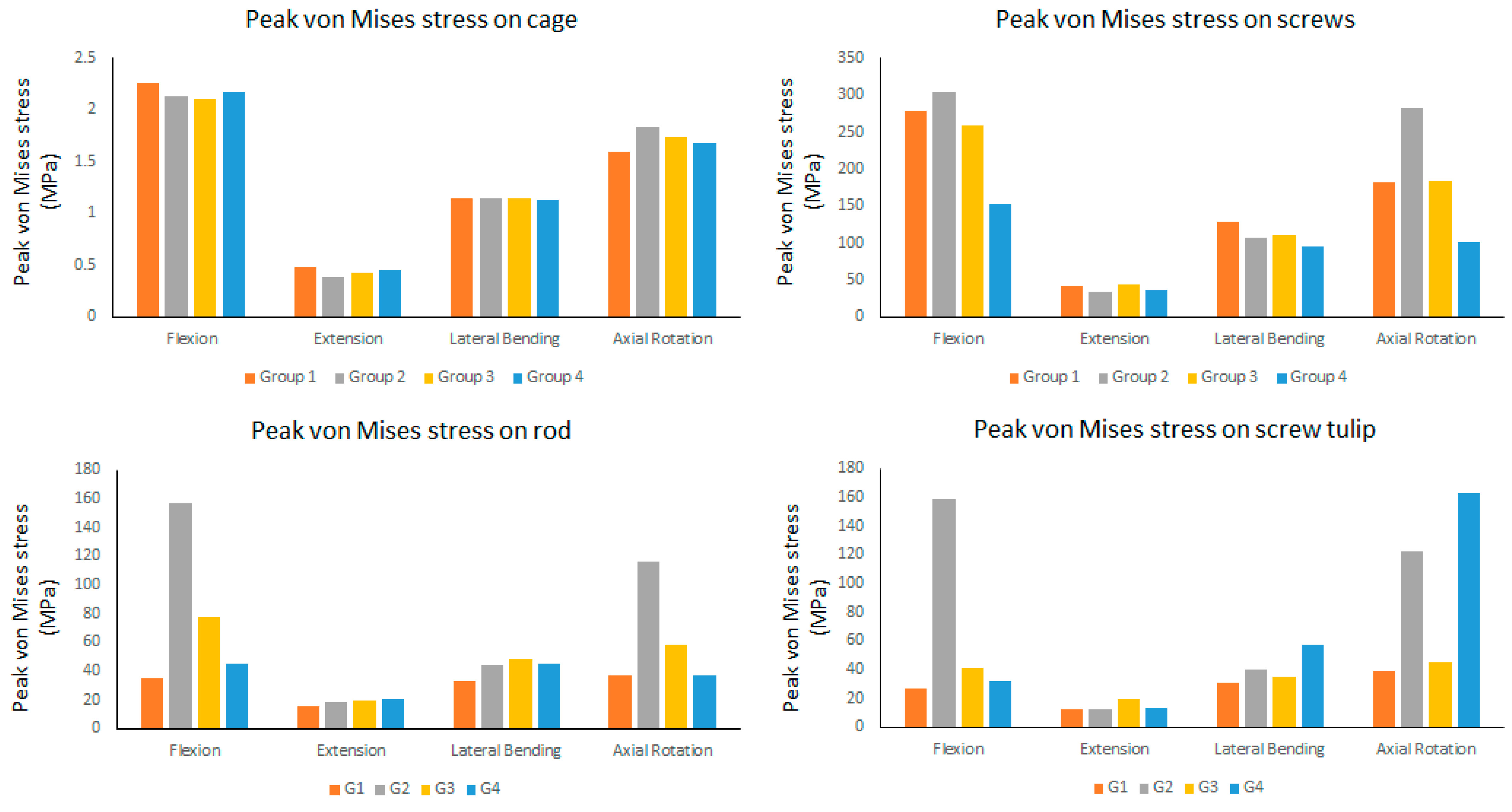
| Maximum von Mises stress on cage (MPa) | Flexion | 2.2643 | 2.1287 | 2.1078 | 2.1681 |
| Extension | 0.48433 | 0.38727 | 0.42276 | 0.44886 | |
| Lateral Bending | 1.144 | 1.1426 | 1.1388 | 1.1321 | |
| Axial Rotation | 1.5995 | 1.8331 | 1.7327 | 1.6753 | |
| Maximum von Mises stress on screw (MPa) | Flexion | 278.98 | 304.59 | 259.98 | 151.78 |
| Extension | 41.203 | 33.009 | 43.554 | 35.291 | |
| Lateral Bending | 128.43 | 106.99 | 111.12 | 94.951 | |
| Axial Rotation | 181.69 | 283.02 | 184.61 | 101.42 | |
| Maximum von Mises stress on rod (MPa) | Flexion | 35.291 | 156.740 | 77.120 | 44.687 |
| Extension | 15.342 | 18.377 | 19.979 | 20.651 | |
| Lateral Bending | 32.976 | 44.394 | 47.588 | 45.462 | |
| Axial Rotation | 36.397 | 115.720 | 58.548 | 37.100 | |
| Maximum von Mises stress on screw tulip (MPa) | Flexion | 26.592 | 158.63 | 40.654 | 31.28 |
| Extension | 12.445 | 12.318 | 19.267 | 13.312 | |
| Lateral Bending | 30.308 | 40.019 | 34.393 | 57.484 | |
| Axial Rotation | 39.04 | 122.25 | 44.963 | 162.73 |
Publisher’s Note: MDPI stays neutral with regard to jurisdictional claims in published maps and institutional affiliations. |
© 2021 by the authors. Licensee MDPI, Basel, Switzerland. This article is an open access article distributed under the terms and conditions of the Creative Commons Attribution (CC BY) license (https://creativecommons.org/licenses/by/4.0/).
Share and Cite
Su, K.-C.; Chen, K.-H.; Pan, C.-C.; Lee, C.-H. Biomechanical Evaluation of Cortical Bone Trajectory Fixation with Traditional Pedicle Screw in the Lumbar Spine: A Finite Element Study. Appl. Sci. 2021, 11, 10583. https://doi.org/10.3390/app112210583
Su K-C, Chen K-H, Pan C-C, Lee C-H. Biomechanical Evaluation of Cortical Bone Trajectory Fixation with Traditional Pedicle Screw in the Lumbar Spine: A Finite Element Study. Applied Sciences. 2021; 11(22):10583. https://doi.org/10.3390/app112210583
Chicago/Turabian StyleSu, Kuo-Chih, Kun-Hui Chen, Chien-Chou Pan, and Cheng-Hung Lee. 2021. "Biomechanical Evaluation of Cortical Bone Trajectory Fixation with Traditional Pedicle Screw in the Lumbar Spine: A Finite Element Study" Applied Sciences 11, no. 22: 10583. https://doi.org/10.3390/app112210583
APA StyleSu, K.-C., Chen, K.-H., Pan, C.-C., & Lee, C.-H. (2021). Biomechanical Evaluation of Cortical Bone Trajectory Fixation with Traditional Pedicle Screw in the Lumbar Spine: A Finite Element Study. Applied Sciences, 11(22), 10583. https://doi.org/10.3390/app112210583