
A Parallel Robot with Torque Monitoring for Brachial Monoparesis Rehabilitation Tasks

 ,
,  ,
, 
 ,
,  ,
,  and
and
Abstract
:1. Introduction
2. Materials and Methods
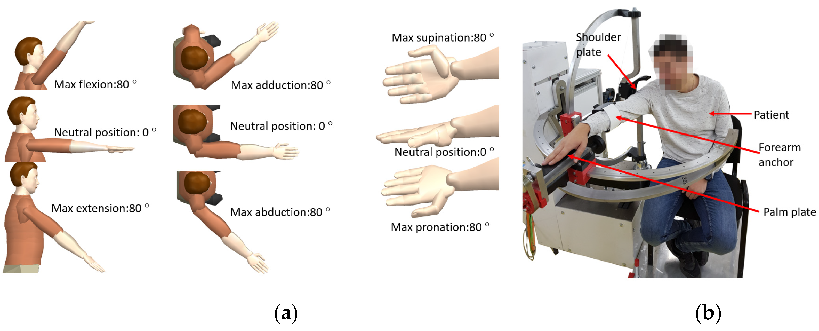
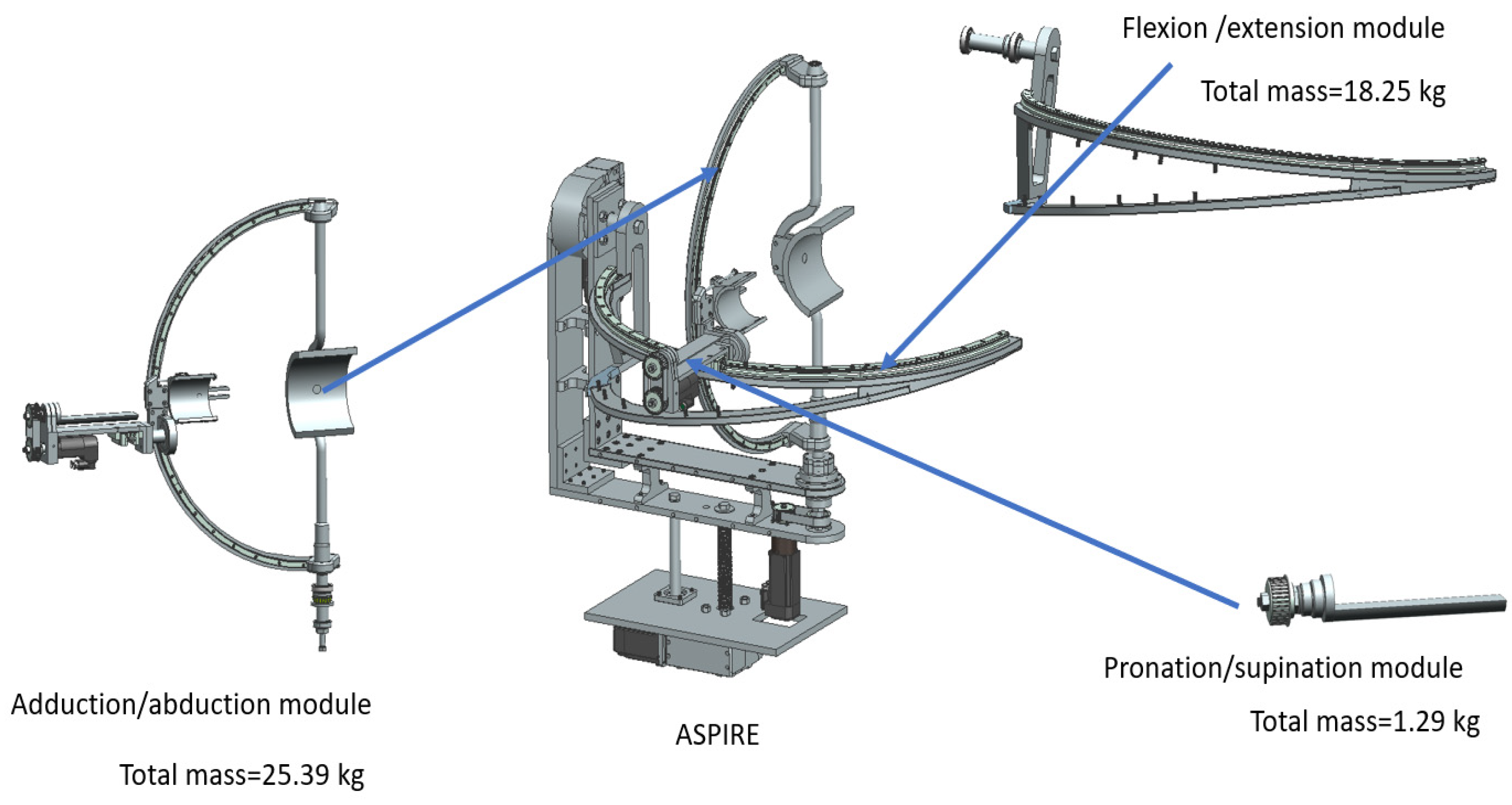
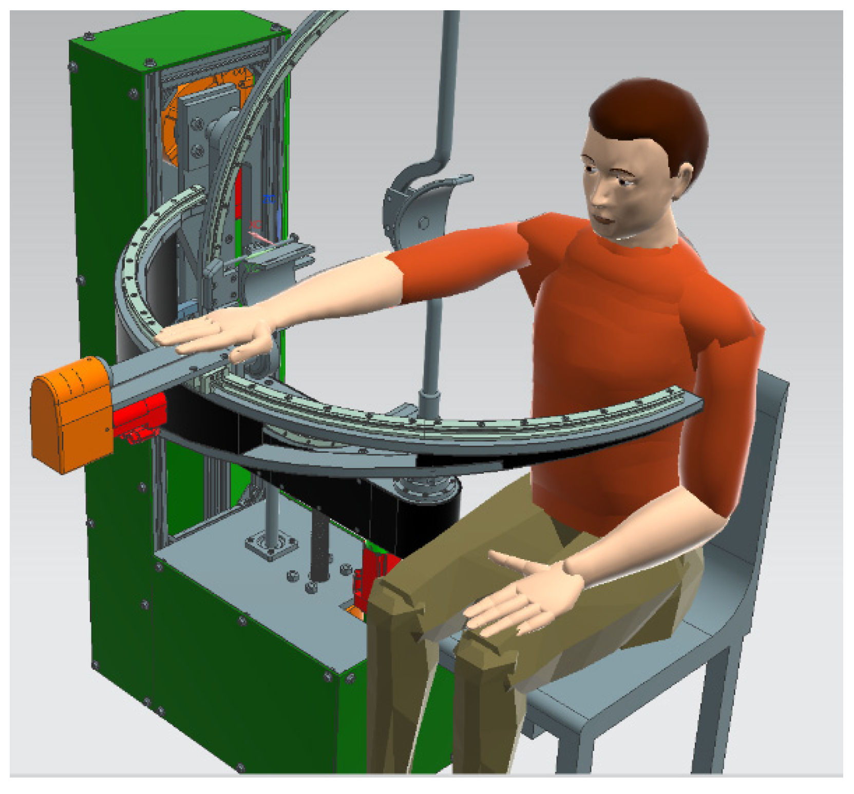
2.1. Short Description of ASPIRE
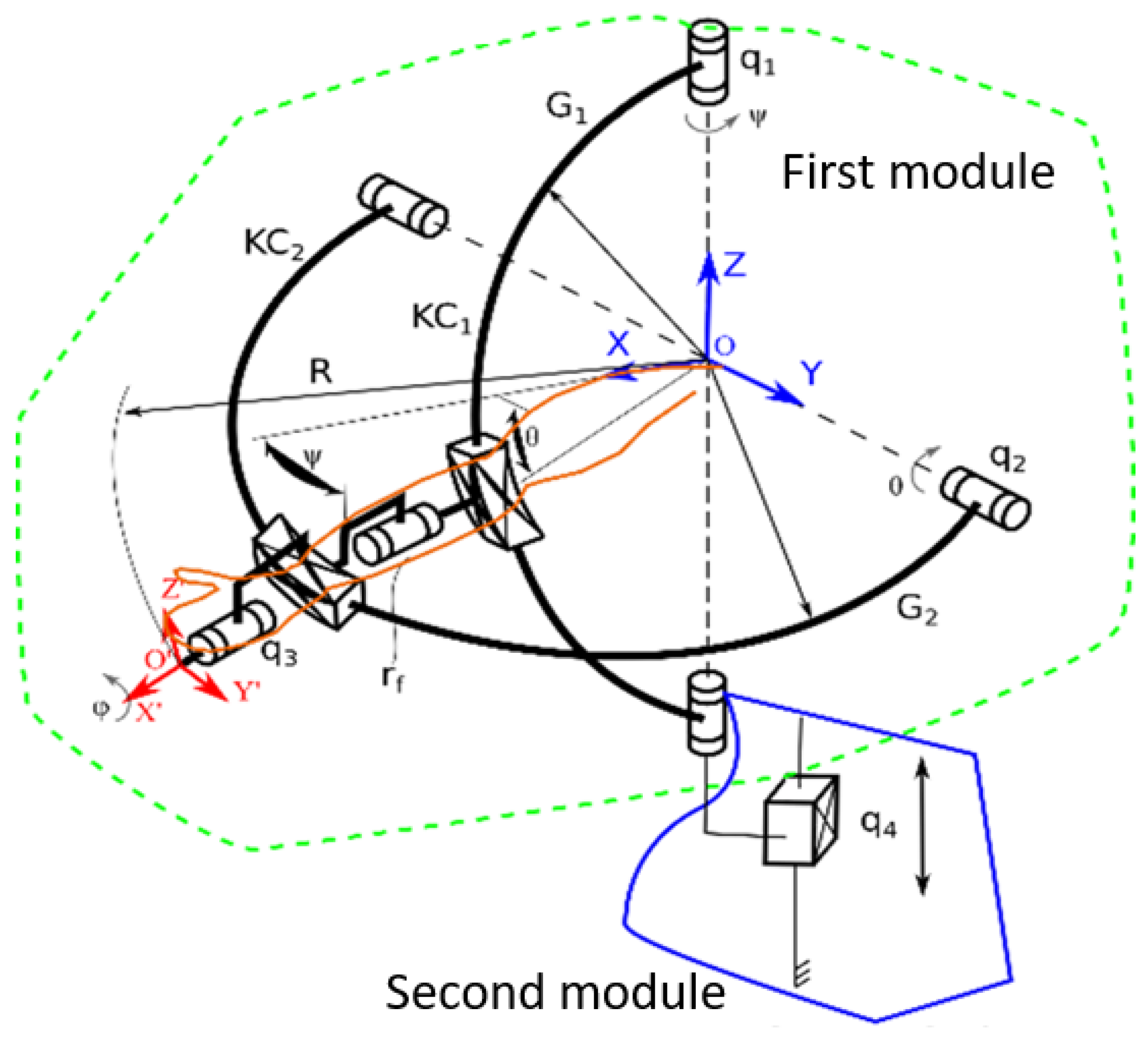
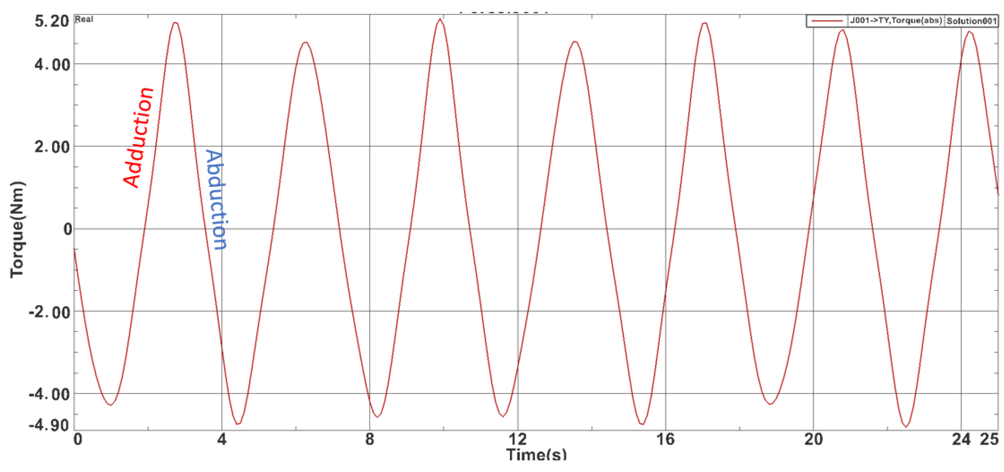
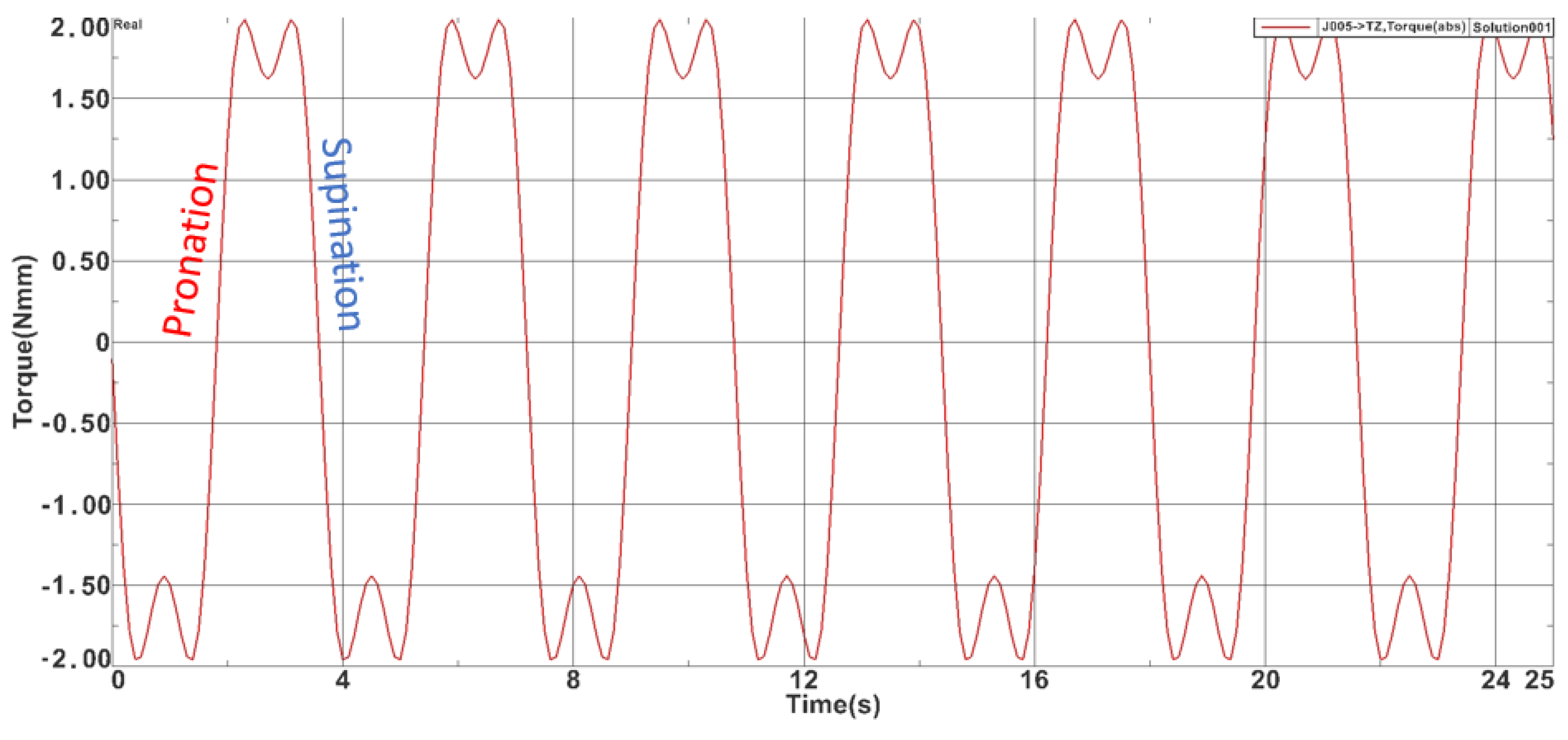
2.2. The Dynamic Analysis of ASPIRE
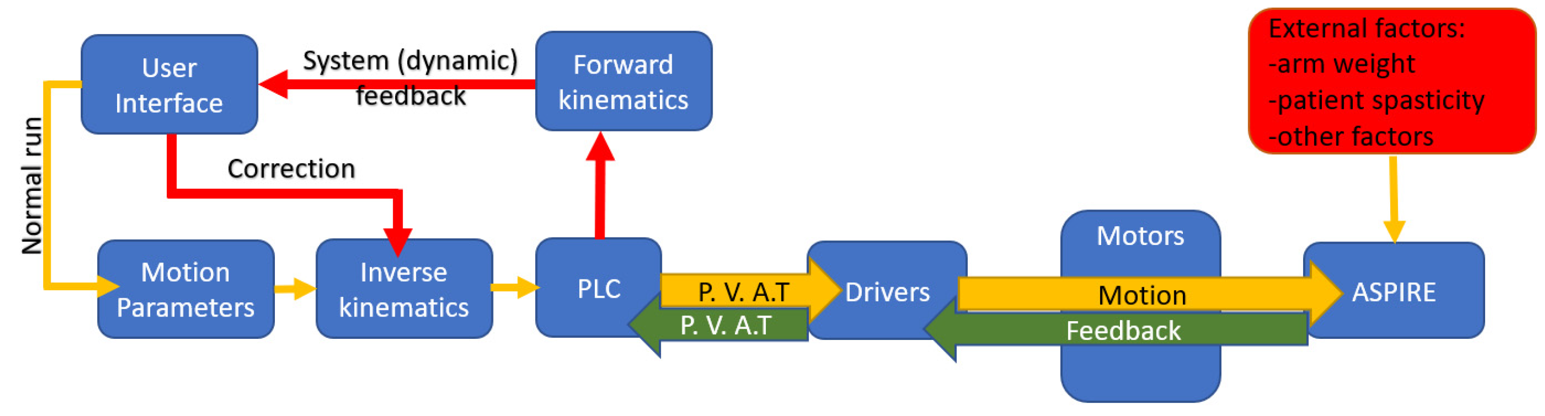
2.3. The Development of Torque Monitoring System
- ✓
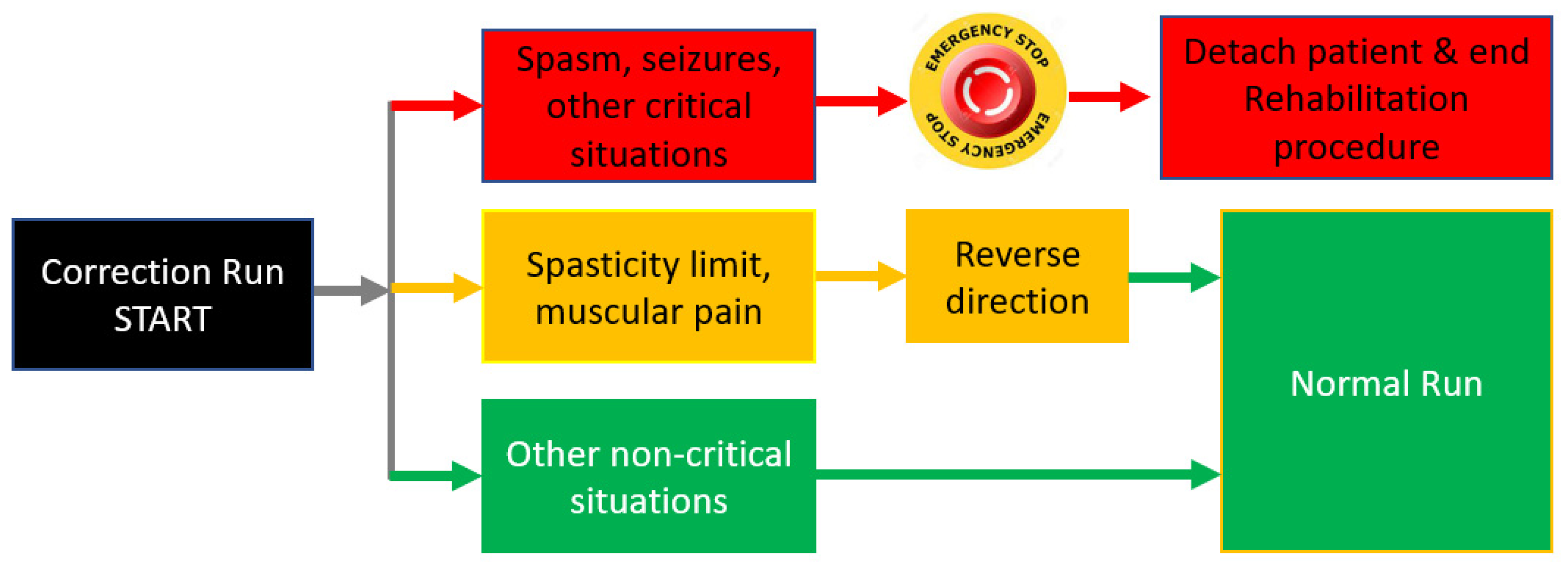
- The first scenario (Red scenario) implies spasm seizures or other critical situations that may endanger the patient. In this case the operator must press the emergency button and the patient is detached from the rehabilitation robot and primary care is administrated. The procedure may be resumed when the patient is in stable condition. This scenario is represented with red arrows and red blocks in Figure 9, and the output of this scenario is the end of the rehabilitation procedure due to unplanned events.
- ✓
- The second scenario (Yellow scenario) includes reaching a spasticity limit or striving muscular pain. In this case, the system may return to the normal run after reversing direction. The system may re-enter the correction run mode when/if the spasticity limit is reached in the opposite direction. This scenario is represented with yellow arrows and yellow blocks in Figure 9 and the output of this scenario is Normal Run, the system that resumes the rehabilitation procedure until the next event.
- ✓
- The third scenario (Green scenario) is related to some non-critical situations (the patient rearranged his position, tremor, etc.). In this case the physiotherapist may resume the normal run. This scenario is represented with green arrows and green blocks in Figure 9, and the output of the scenario is also Normal Run, the system that resumes the rehabilitation motion until the next event.
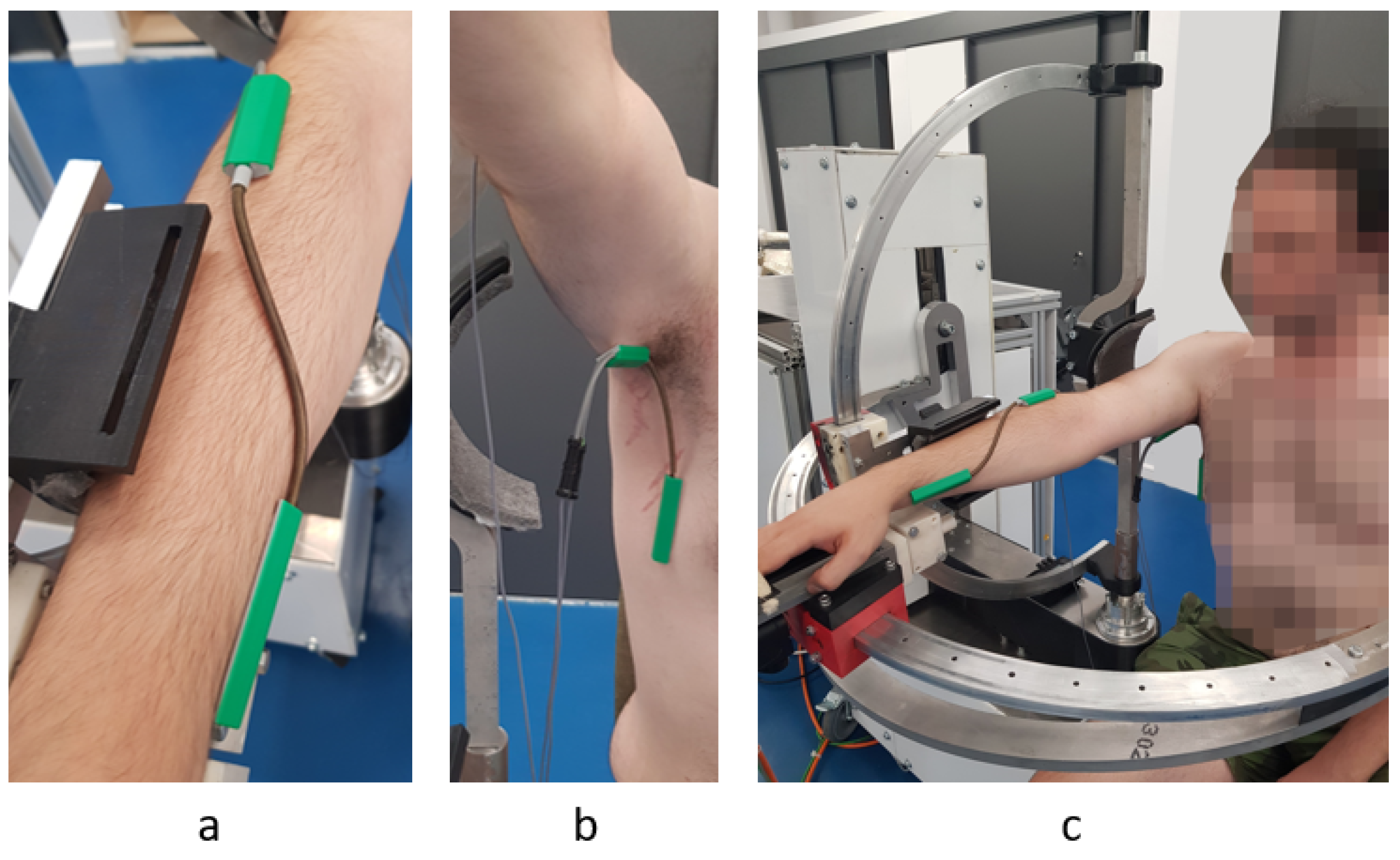
2.4. Experimental Setup and Torque Control Validation
3. Results
4. Discussion
5. Conclusions
Author Contributions
Funding
Institutional Review Board Statement
Informed Consent Statement
Data Availability Statement
Conflicts of Interest
References
- Healthline. Available online: https://www.healthline.com/health/monoplegia (accessed on 15 July 2021).
- Garcia, R.V. The Brachial and Crural Indices of Modern North American Population. Master’s Thesis, Texas State University, San Marcos, TX, USA, 2015, unpublished. [Google Scholar]
- Iqbal, J.; Bruno, A.; Berger, M. Stroke causing pure brachial monoparesis. J. Stroke Cerebrovasc. Dis. 1995, 5, 88–90. [Google Scholar] [CrossRef]
- Department of Economic and Social Affairs. World Population Ageing 2017 Highlights; United Nations: New York, NY, USA, 2017. [Google Scholar]
- Eyigor, S.; Durmaz, B.; Karapolat, H. Monoparesis with complex regional pain syndrome-like symptoms due to brachial plexopathy caused by varicella zoster virus: A case report. Arch. Phys. Med. Rehabil. 2006, 87, 1653–1655. [Google Scholar] [CrossRef] [PubMed]
- NHS Funding. Available online: https://nhsfunding.info/ (accessed on 15 July 2021).
- Baniqued, P.D.E.; Stanyer, E.C.; Awais, M.; Alazmani, A.; Jackson, A.E.; Mon-Williams, M.A.; Mushtaq, F.; Holt, R.J. Brain–computer interface robotics for hand rehabilitation after stroke: A systematic review. J. Neuroeng. Rehabil. 2021, 18, 1–25. [Google Scholar] [CrossRef] [PubMed]
- Gull, M.A.; Thoegersen, M.; Bengtson, S.H.; Mohamadi, M.; Struijk, L.N.S.A.; Moeslund, T.B.; Bak, T.; Bai, S. A 4-DOF upper limb exoskeleton for physical assistance: Design, modeling, control and performance evaluation. Appl. Sci. 2021, 11, 5856. [Google Scholar] [CrossRef]
- Chaparro-Rico, B.D.M.; Cafolla, D.; Castillo-Castaneda, E.; Ceccarelli, M. Design of arm exercises for rehabilitation assistance. J. Eng. Res. 2020, 8, 204–218. [Google Scholar] [CrossRef]
- Li, J.; Cao, Q.; Dong, M.; Zhang, C. Compatibility evaluation of a 4-DOF ergonomic exoskeleton for upper limb rehabilitation. Mech. Mach. Theory 2021, 156, 104146. [Google Scholar] [CrossRef]
- Kim, B.; Deshpande, A.D. An upper-body rehabilitation exoskeleton Harmony with an anatomical shoulder mechanism: Design, modeling, control, and performance evaluation. Int. J. Robot. Res. 2017, 36, 414–435. [Google Scholar] [CrossRef]
- Brahmi, B.; Driscoll, M.; El Bojairami, I.K.; Saad, M.; Brahmi, A. Novel adaptive impedance control for exoskeleton robt rehabilitation using a nonlinear time-delay disturbance observer. ISA Trans. 2021, 108, 381–392. [Google Scholar] [CrossRef]
- Paolucci, T.; Agostini, F.; Mangone, M.; Berneti, A.; Pezzi, L.; Liotti, V.; Recubini, E.; Cantarella, C.; Bellomo, R.G.; D′Azurio, C.; et al. Robotic rehabilitation for end-effector device and botulinum toxin in upper limb rehabilitation in chronic post-stroke patients: An integrated rehabilitative approach. Neurol. Sci. 2021. [Google Scholar] [CrossRef]
- DeBoon, B.M.; Foley, R.C.A.; Nokleby, S.B.; La Delfa, N.J.; Rossa, C. Nine degree-of-freedom kinematic modeling of the upper-limb complex for constrained workspace evaluation. J. Biomech. Eng. 2021, 143, 1–13. [Google Scholar] [CrossRef]
- Vaida, C.; Carbone, G.; Major, K.; Major, Z.; Plitea, N.; Pisla, D. On human robot interaction modalities in the upper limb rehabilitation after stroke. Acta Tech. Napoc. Ser. Appl. Math. Mech. Eng. 2017, 60, 91–102. [Google Scholar]
- Motos, A.B.; Blanco, A.; Badesa, F.J.; Barios, J.A.; Zollo, L.; Garcia-Aracil, N. Human arm joints reconstruction algorithm in rehabilitation therapies assisted bt end-effector robotic devices. J. Neuroeng. Rehabil. 2018. [Google Scholar] [CrossRef] [Green Version]
- Zhang, L.; Guo, S.; Sun, Q. Development and assist-As-needed control of an end-effector upper limb rehabilitation robot. Appl. Sci. 2020, 10, 6684. [Google Scholar] [CrossRef]
- Vaida, C.; Pisla, D.; Schadlbauer, J.; Husty, M.; Plitea, N. Kinematic analysis of an innovative medical parallel robot using study parameters. In New Trends in Medical and Service Robots. Mechanisms and Machine Science; Wenger, P., Chevallereau, C., Pisla, D., Bleuler, H., Rodić, A., Eds.; Springer: Cham, Switzerland, 2016; Volume 39, Available online: https://doi.org/10.1007/978-3-319-30674-2_7 (accessed on 10 July 2021). [CrossRef]
- Vaida, C.; Plitea, N.; Gherman, B.; Szilaghyi, A.; Galdau, B.; Cocorean, D.; Covaciu, F.; Pisla, D. Structural analysis and synthesis of parallel robots for brachytherapy. In New Trends in Medical and Service Robots. Mechanisms and Machine Science; Pisla, D., Bleuler, H., Rodic, A., Vaida, C., Pisla, A., Eds.; Springer: Cham, Switzerland, 2014; Volume 16, Available online: https://doi.org/10.1007/978-3-319-01592-7_14 (accessed on 10 July 2021). [CrossRef]
- Pisla, D.; Plitea, N.; Gherman, B.G.; Vaida, C.; Pisla, A.; Suciu, M. Kinematics and design of a 5-DOF parallel robot used in minimally invasive surgery. In Advances in Robot Kinematics: Motion in Man and Machine; Lenarcic, J., Stanisic, M., Eds.; Springer: Dordrecht, The Netherlands, 2010; Available online: https://doi.org/10.1007/978-90-481-9262-5_11 (accessed on 10 July 2021). [CrossRef]
- Schonstein, C. Considerations about matrix exponentials in geometrical modeling of the robots. Acta Tech. Napoc. Ser. Appl. Math. Mech. Eng. 2019, 62, 337–342. [Google Scholar]
- Schonstein, C. Kinematic control functions for a serial robot structure based on the time derivative Jacobian matrix. Acta Tech. Napoc. Ser. Appl. Math. Mech. Eng. 2018, 61, 219–224. [Google Scholar]
- Nedezki, C.M. Position problem for 3rpr 3-mobile plan parallel manipulator. Acta Tech. Napoc. Ser. Appl. Math. Mech. 2013, 56, 317–322. [Google Scholar]
- Zhao, F.; Yang, Z.; Li, Z.; Gua, D.; Li, H. Extract executable action sequences from natural language instructions based on DQN for medical service robots. Int. J. Comput. Commun. Control 2021, 16. [Google Scholar] [CrossRef]
- Escalante, F.M.; Jutinico, A.L.; Jaimes, J.C.; Terra, M.H.; Siqueira, A.A.G. Markovian robust filtering and control applied to rehabilitation robotics. IEEE/ASME Trans. Mechatron. 2021, 26. [Google Scholar] [CrossRef]
- Kim, D.; Lee, J. Robust control of a system with pneumatic spring. J. Frankl. Inst. 2021, 358, 555–574. [Google Scholar] [CrossRef]
- Masengo, G.; Zhang, X.D.; Yin, G.; Alhassan, A.B.; Dong, R.L.; Orban, M.; Mudaheranwa, E. A design of lower limb rehabilitation robot and its control for passive training. In Proceedings of the 10th Institute of Electrical and Electronics Engineers International Conference on Cyber Technology in Automation, Control, and Intelligent Systems (IEEE-CYBER 2020), Xi’an, China, 10–13 October 2020; pp. 152–157. [Google Scholar]
- Antal, T.A. Addendum modification of spur gears with equalized efficiency at the points where the meshing starts and ends. Mechanika 2016, 6, 480–485. [Google Scholar]
- Antal, T.A.; Antal, A. The use of genetic algorithms for the design of mechatronic transmission with improved operating conditions. In Proceedings of the 3rd International Conference on Human System Interaction, Rzeszow, Poland, 13–15 May 2010. [Google Scholar] [CrossRef]
- Aliabadi, M.; Mashayekhifard, J.; Moha, B. Intelligent and classic control of rehabilitation robot with robust PID and Fuzzy methods. Majlesi J. Mechatron. Syst. 2020, 9, 31–36. [Google Scholar]
- Bouteraa, Y.; Abdallah, I.B.; ElMogy, A.; Tariq, U.; Ahmad, T. A fuzzy logic architecture for rehabilitation robotic systems. Int. J. Comput. Commun. Control. 2020, 15, 1–17. [Google Scholar] [CrossRef]
- Lyu, S.; Cheah, C.C. Human-robot interaction control based on a general energy shaping method. IEEE Trans. Control Syst. Technol. 2020, 28, 2445–2460. [Google Scholar] [CrossRef]
- Shi, D.; Zhang, W.X.; Zhang, W.; Ju, L.H.; Ding, X.L. Human-centered adaptive control of lower limb rehabilitation robot based on human-robot interaction dynamic. Mech. Mach. Theory 2021, 162. [Google Scholar] [CrossRef]
- Bouteraa, Y.; Ben Abdallah, I.; Alnowaiser, K.; Ibrahim, A. Smart solution for pain detection in remote rehabilitation. Alex. Eng. J. 2021, 60, 3485–3500. [Google Scholar] [CrossRef]
- Erwin, A.; McDonald, C.G.; Moser, N.; O′Malley, M.K. The SE-AssessWrist for robot-aided assessment of wrist stiffness and range of motion: Development and experimental validation. J. Rehabil. Assist. Technol. Eng. 2021, 8. [Google Scholar] [CrossRef]
- Vaida, C.; Plitea, N.; Pîslă, D.; Carbone, G.; Gherman, B.; Ulinici, I.; Pislă, A. Spherical Robot for Medical Recovery of Upper Limb Proximal Area. Patent RO132233-A0, 29 November 2017. [Google Scholar]
- Tucan, P.; Plitea, N.; Vaida, C.; Gherman, B.; Carbone, G.; Luchian, I.; Pisla, D. Inverse dynamics and simulation of a parallel robot used in shoulder rehabilitation. In New Trends in Mechanism and Machine Science. EuCoMeS 2020. Mechanisms and Machine Science; Pisla, D., Corves, B., Vaida, C., Eds.; Springer: Cham, Switzerland, 2020; Volume 89. [Google Scholar]
- Plagenhoef, S.; Gaunor, E.V.; Abdelnour, T. Anatomical data for analyzinghuman motion. J. Res. Q. Exerc. Sport 1983, 54, 169–178. [Google Scholar] [CrossRef]
- Tucan, P.; Vaida, C.; Plitea, N.; Pisla, A.; Carbone, G.; Pisla, D. Risk-based assessment engineering of a parallel robot used in post-stroke upper limb rehabilitation. Sustainability 2019, 11, 2893. [Google Scholar] [CrossRef] [Green Version]
- Major, Z.Z.; Vaida, C.; Major, K.A.; Tucan, P.; Simori, G.; Banica, A.; Brusturean, E.; Burz, A.; Craciunas, R.; Ulinici, I.; et al. The impact of robotic rehabilitation on the motor system in neurological diseases. A multimodal neurophysiological approach. Int. J. Environ. Res. Public Health 2020, 17, 6557. [Google Scholar] [CrossRef]
- Tucan, P.; Vaida, C.; Ulinici, I.; Banica, A.; Burz, A.; Pop, N.; Birlescu, I.; Gherman, B.; Plitea, N.; Antal, T.; et al. Optimization of the ASPIRE spherical parallel rehabilitation robot based on its clinical evaluation. Int. J. Environ. Res. Public Health 2021, 18, 3281. [Google Scholar] [CrossRef]
- Vaida, C.; Ulinici, I.; Banica, A.; Burz, A.; Gherman, B.; Tucan, P.; Pisla, A.; Carbone, G.; Pisla, D. First clinical evaluation of a spherical robotic system for shoulder rehabilitation. In New Trends in Medical and Service Robotics; MESROB 2020. Mechanisms and Machine, Science; Rauter, G., Cattin, P.C., Zam, A., Riener, R., Carbone, G., Pisla, D., Eds.; Springer: Cham, Switzerland, 2020; Volume 93, Available online: https://doi.org/10.1007/978-3-030-58104-6_8 (accessed on 10 July 2021). [CrossRef]
- B&R Industrial Automation GmbH. Available online: https://www.br-automation.com/de/ (accessed on 21 July 2021).
- Biometrics Ltd. Available online: https://www.biometricsltd.com/ (accessed on 21 July 2021).
- MatLab. Available online: https://www.mathworks.com/ (accessed on 21 July 2021).


| Risk Factor | Associated Risk | Risk Overcome Measure |
|---|---|---|
| Tremor | The patient may detach from the rehabilitation device. Creates supplementary jerk in the system. | By monitoring the torque, the rehabilitation procedure may be performed with respect to the tremor frequency of the patient |
| Spasticity | May harm the patient arm. May break soft parts in the rehabilitation system. | By monitoring the torque in the system, the spasticity may be identified. In addition, using torque monitoring the patient arm may be slowly stretched over the spasticity limit |
| Unable to maintain seating position | The patient may fall and detach from the rehabilitation device. | The patient must be strapped by the rehabilitation chair. The rehabilitation chair must be a sturdy one and allow harness fixtures. |
| Spasms Muscular pain | May harm the patient arm. May break soft parts in the rehabilitation system. | By monitoring the torque in the system, the spasms may be identified. When spasms occur, the system requires medical intervention and the motion is stopped until further instructions. |
| Headaches/Migraine, Depression | The patient cannot concentrate to the rehabilitation process. | Here, multimodal simulation and interactive procedures can be of help. By keeping the patient busy, he/she will focus more on the tasks. In this case, torque-based control allows multiple exercises, including AR ones. |
| Seizures | May harm the patient arm. May break soft parts in the rehabilitation system. | By monitoring the torque in the system, the seizures may be identified. When seizures occur, the system require medical intervention and the motion is stopped until further instructions. |
| Wounds Skin diseases | Cannulas or wounds in anchor points may create discomfort during the rehabilitation | When the patient presents wounds over the anchor zones, bandage must be applied before attaching the rehabilitation device |
| Overall poor health state | Pulmonary, respiratory, cardiovascular diseases may influence the effects of the rehabilitation. | When enrolling the physical rehabilitation, the patient must not have diseases that may obstruct the physical therapy. |
| Segment | Segment Weight | |
|---|---|---|
| Men | Woman | |
| Hand | 0.526 kg | 0.306 kg |
| Forearm | 1.519 kg | 0.965 kg |
| Upper arm | 2.633 kg | 1.777 kg |
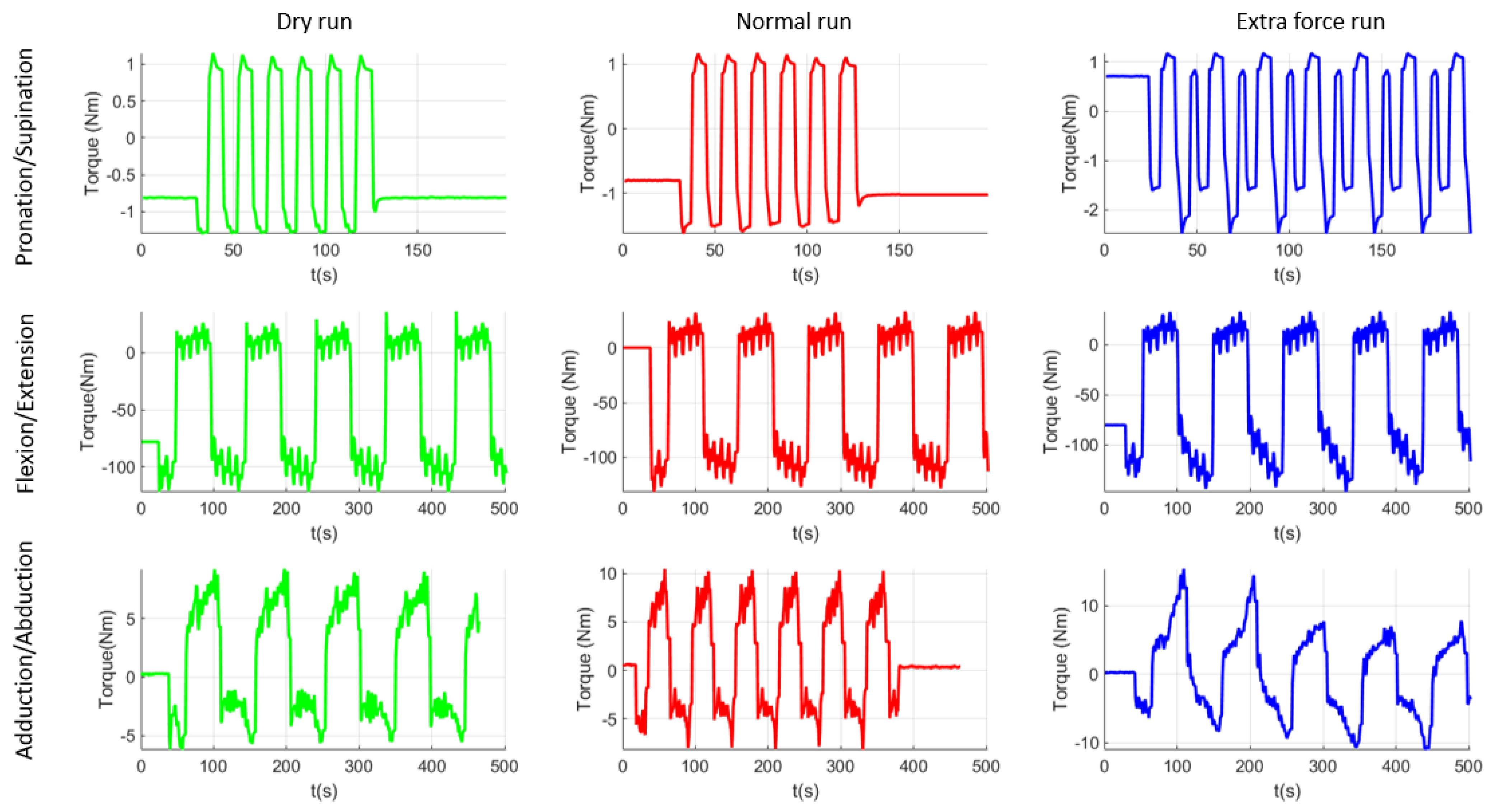
| Rehabilitation Motion | Maxim Torque Recorded (Nm) | |||||||
|---|---|---|---|---|---|---|---|---|
| Virtual Sim. | SD | Dry run | SD | Normal run | SD | Resisting test | SD | |
| Pronation/Supination | 1.91 | 0.6985 | 1.10 | 0.0759 | 1.62 | 0.0850 | 2.45 | 0.1227 |
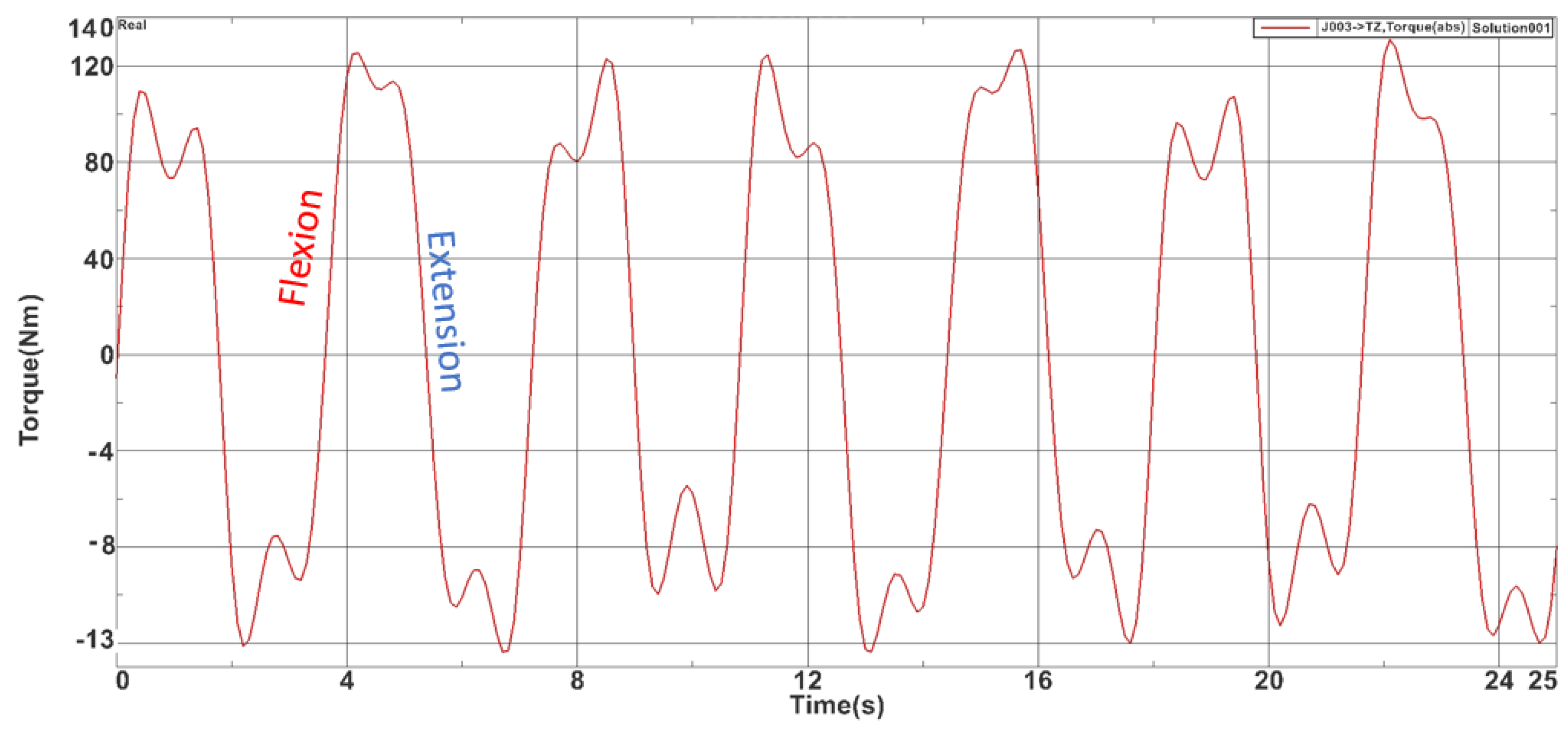
| Flexion/Extension | 127.2 | 1.1354 | 122 | 1.2097 | 131.39 | 1.2378 | 147.37 | 1.3663 |
| Adduction/Abduction | 5.04 | 0.0495 | 9.20 | 0.0490 | 10.47 | 0.0463 | 14.40 | 0.0591 |
| Percentual difference between different running modes (between max values) | ||||||||
| Pronation/Supination | −43% | +47% | +51% | |||||
| Flexion/Extension | −4% | +7% | +12% | |||||
| Adduction/Abduction | +82% | +13% | +37% | |||||
Publisher’s Note: MDPI stays neutral with regard to jurisdictional claims in published maps and institutional affiliations. |
© 2021 by the authors. Licensee MDPI, Basel, Switzerland. This article is an open access article distributed under the terms and conditions of the Creative Commons Attribution (CC BY) license (https://creativecommons.org/licenses/by/4.0/).
Share and Cite
Pisla, D.; Tarnita, D.; Tucan, P.; Tohanean, N.; Vaida, C.; Geonea, I.D.; Bogdan, G.; Abrudan, C.; Carbone, G.; Plitea, N. A Parallel Robot with Torque Monitoring for Brachial Monoparesis Rehabilitation Tasks. Appl. Sci. 2021, 11, 9932. https://doi.org/10.3390/app11219932
Pisla D, Tarnita D, Tucan P, Tohanean N, Vaida C, Geonea ID, Bogdan G, Abrudan C, Carbone G, Plitea N. A Parallel Robot with Torque Monitoring for Brachial Monoparesis Rehabilitation Tasks. Applied Sciences. 2021; 11(21):9932. https://doi.org/10.3390/app11219932
Chicago/Turabian StylePisla, Doina, Daniela Tarnita, Paul Tucan, Nicoleta Tohanean, Calin Vaida, Ionut Daniel Geonea, Gherman Bogdan, Cristian Abrudan, Giuseppe Carbone, and Nicolae Plitea. 2021. "A Parallel Robot with Torque Monitoring for Brachial Monoparesis Rehabilitation Tasks" Applied Sciences 11, no. 21: 9932. https://doi.org/10.3390/app11219932
APA StylePisla, D., Tarnita, D., Tucan, P., Tohanean, N., Vaida, C., Geonea, I. D., Bogdan, G., Abrudan, C., Carbone, G., & Plitea, N. (2021). A Parallel Robot with Torque Monitoring for Brachial Monoparesis Rehabilitation Tasks. Applied Sciences, 11(21), 9932. https://doi.org/10.3390/app11219932