Abstract
Robots for rehabilitation tasks require a high degree of safety for the interaction with both the patients and for the operators. In particular, high safety is a stable and intuitive control of the moving elements of the system combined with an external system of sensors able to monitor the position of every aspect of the rehabilitation system (operator, robot, and patient) and overcome in a certain measure all the events that may occur during the robotic rehabilitation procedure. This paper presents the development of an internal torque monitoring system for ASPIRE. This is a parallel robot designed for shoulder rehabilitation, which enables the use of strategies towards developing a HRI (human–robot interaction) system for the therapy. A complete analysis regarding the components of the robotic system is carried out with the purpose of determining the dynamic behavior of the system. Next, the proposed torque monitoring system is developed with respect to the previously obtained data. Several experimental tests are performed using healthy subjects being equipped with a series of biomedical sensors with the purpose of validating the proposed torque monitoring strategy and, at the same time, to satisfy the degree of safety that is requested by the medical procedure.
1. Introduction
Monoplegia is a type of paralysis that affects one of the limbs (arm or leg), permanently or temporarily [1].When monoplegia is located on one of the upper limbs it is referred to as brachial monoplegia and if it is located on one of the lower limbs it is referred to as crural monoplegia [2].There are several neurological disorders that may cause monoplegia, most common are: stroke, cerebral palsy, Guillain–Barre syndrome, peripheral neuropathy, Lou Gehrig’s disease, head or spinal trauma, and neuropathy. With respect to the neurological disease that caused the monoplegia, sometimes it can evolve to paraplegia or hemiplegia. A less severe form of monoplegia is called monoparesis and monoparesis of the upper limb is referred as brachial monoparesis. Pure brachial monoparesis is usually caused by stroke [3] and its effects are weakness, spasticity, numbness, paralysis, pain, and headaches. Stroke may occur in any age group, but it is more frequent in ages of 55 to 85. In 2017 United Nations released a series of highlights regarding trending in the ageing of the worldwide population [4]. According to these statistics in 2017 population aged over 60 years numbered 962 million worldwide. The same study reveals that by 2030 the number will rise to 1.41 billion and by 2050 it will surpass 2 billion.
There is no cure for brachial monoparesis but with the help of physical therapy performed under the supervision and help of a physiotherapist, some muscular tonus and functionalities may be regained [5]. Physical therapy of brachial monoparesis implies repetitive motion of the upper limb with motor deficit. With respect to the affected area (shoulder, elbow, wrist, fingers) different rehabilitation motions are used, targeting the specific motion of each articulation, but each motion must be done by special medical personnel.
The capability of the NHS (National Health System) to provide medical care for each person in need has been seriously stressed lately. Previous statistics preconized that in 2030 the NHS will be unable to provide medical care for the people in need due to personal shortage [5]; momentarily there is a crisis regarding staff recruiting in the NHS [6] so this prevision seams quite close. All the above data raises a question: Who will provide care for the ones in need in the near future? There is no simple and straight forward answer to this question, but there are research domains trying to overcome the predicted personnel crisis and one of these domains is medical robotics. Developing robotic solutions for the medical care should not imply substituting the medical personnel from the operation/therapy room but providing means for the health careers to deliver a more precise and effective treatment with less effort and allowing them to serve more efficiently a larger number of patients. The effectiveness of the physical therapy when discussing rehabilitation of stroke or other neurological disease survivors is largely dependent on how fast the treatment is delivered to the patient. With the help of robotic devices this treatment may be delivered in the acute phase, immediately after patient stabilization, following a stroke incident.
Robotic devices for brachial monoparesis should be able to mold the impaired upper limb and mimic the rehabilitation motion of the targeted anatomical articulation. Several solutions for upper limb rehabilitation have been developed; one can classify these solutions in exoskeletons and end-effectors systems [7].
Gull et al. [8] developed an adaptive 4-DOF exoskeleton for upper limb rehabilitation, mountable on a wheelchair, able to carry the patient throughout daily activities like eating and drinking. The exoskeleton uses an open-chain structure to mimic the anatomy of the upper limb joints and it is divided into three modules: shoulder module, elbow module, and wrist module. The exoskeleton uses a proportional-derivative control method implemented using ROS (Robotic Operating System) and it uses the dynamic model of the mechanism and the weights of the upper limb segments to hold the arm in position during daily tasks. The system has yet to undergo clinical trials and user acceptance.
Studies regarding the development of upper limb exoskeletons were also published in [9,10,11,12], some of them being based on the study of the dynamic behavior of the exoskeletons and the possibility to control the robotic solutions to maximize the efficiency of the rehabilitation.
Paolucci [13] presents MOTORE (Mobile Robot for upper limb neuro-ortho rehabilitation), an end-effector based robotic system for upper limb rehabilitation able to offer different modes of operation ranging from offering support for functional patients to assisted movement for patients with severe hemiplegia. The device comes with a visual feedback system that helps in performing daily tasks such reaching and carrying with the goal of rehabilitating the shoulder and the elbow. The device underwent clinical trials resulting in a good efficiency of the rehabilitation, reduction of spasticity, and improvements in the upper limb functions and at the same time reduction of the pain. The authors also stated a series of limitations of the study like neuropsychological limitations, absence of instrumental evaluation to assess the correlation between the variation of spasticity and muscle strength, and lack of analysis at aphasia level. There are several studies regarding the development of end-effector based rehabilitation devices [14,15,16,17], some of them developed until the stage of clinical trials.
All the above studies have in common use of several tools to achieve the safety required by the medical procedure. The safety may be achieved through an effective correlation between the kinematics of the medical robot [18,19,20,21,22,23] and the control system [24,25,26,27,28,29,30,31] used to actuate the robotic structure with respect to human–robot interactions [32,33,34,35].
Regarding rehabilitation robots where human–robot interaction is required, the safety of the patient during the rehabilitation procedure should be of utmost importance. For achieving a high level of safety, the dynamic behavior of the robotic structure should be carefully and completely analyzed, and the control system should be able to perform the rehabilitation procedure with respect to the data obtained after the dynamic behavior analysis and at the same time to be able to interact with the patient during the procedure in order to react to any deviation from the initial rehabilitation plan.
This paper focuses on the development of an internal torque monitoring system for a rehabilitation system. Section 2.1 of the paper presents the ASPIRE robotic structure. The mechanical structure passed through a few optimization phases to improve the behavior of the structure during the rehabilitation procedure. The dynamic behavior of each rehabilitation module is studied in Section 2.2. to obtain the nominal working torques and the torque monitoring system is developed with respect to the obtained results regarding the dynamic behavior in Section 2.3 followed by Section 2.4 where the torque monitoring system is experimentally tested and validated. The third section of the paper consists of results of the research, followed by discussions and conclusions.
2. Materials and Methods
2.1. Short Description of ASPIRE
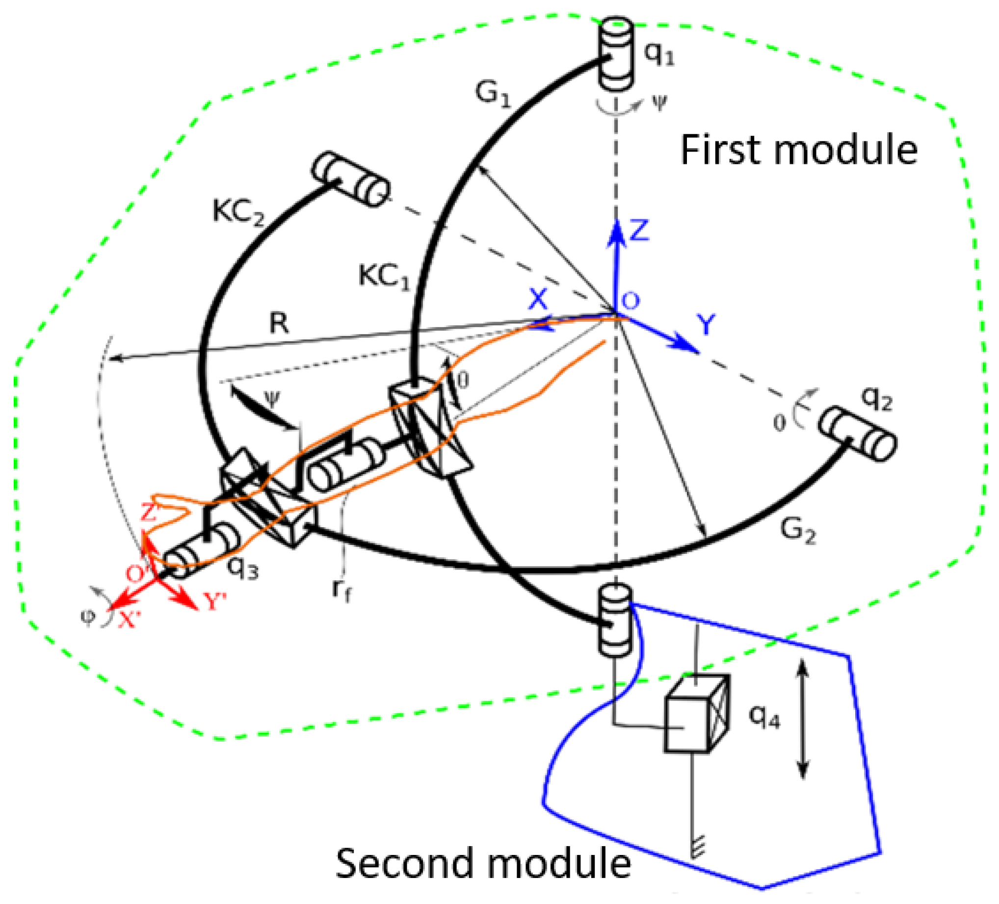
ASPIRE is a parallel robot for shoulder rehabilitation, whose design is outlined in [36]. The robotic structure is based on a spherical architecture, and it is capable of performing flexion, extension, adduction, and abduction of the shoulder. The system is also able to perform the pronation and supination of the forearm. The kinematic scheme of ASPIRE robotic structure is presented in Figure 1 [37]. The robot is composed of two modules: the first module is the one containing tools for performing the shoulder rehabilitation procedure (one axis for each rehabilitation motion). The OXYZ reference system indicates the center of shoulder joint, and all rehabilitation motions are described using this point. The adduction-abduction motion is performed using the q1 axis that rotates a circular guide (G1) attached to circular guide G2 using a passive revolute joint (rf). The flexion-extension motion is performed by q2 axis that rotates the circular guide G2. The interconnected circular guides impose a spherical trajectory of O’X’Y’Z’ reference system with respect to the shoulder joint center. The pronation-supination motion is performed using axis q3 that reorients the O’X’Y’Z’ reference system around X’ axis.
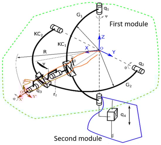
Figure 1.
Kinematic scheme of ASPIRE [36].
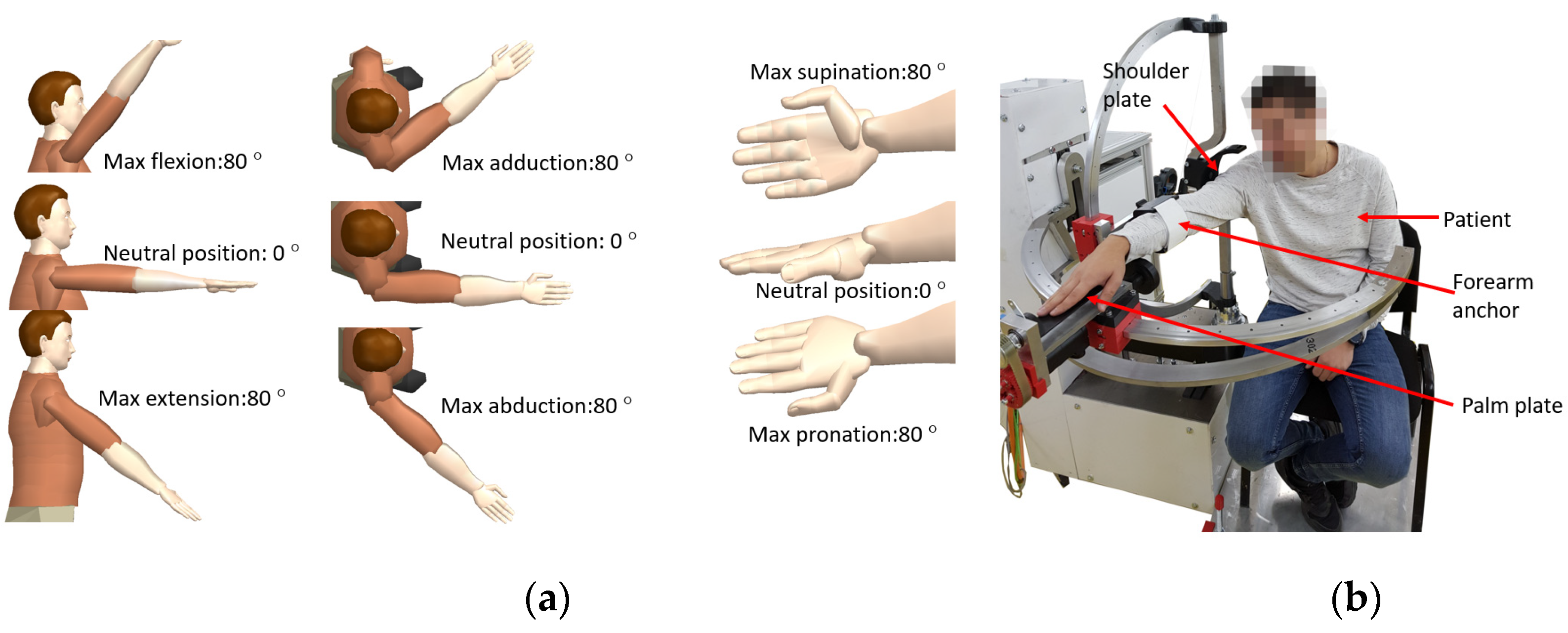
The second module is used for adjusting the rehabilitation mechanisms based on patient height and it contains one axis (q4) that displaces vertically the OXYZ reference system of the structure. The motion amplitudes for each rehabilitation motions are ±80 degrees [38] and the limb positions during the rehabilitation may be seen in Figure 2a. During the rehabilitation procedure, the patient is seated, and his right shoulder is pressed against the shoulder plate of the robot; the forearm is attached within the forearm support. His palm is placed on the pronation-supination mechanism and held in place by an elastic band as it can be seen in Figure 2b where the experimental model of the ASPIRE is presented.

Figure 2.
Arm position during rehabilitation and motion amplitudes (a); patient position during rehabilitation, experimental model (b).
At the end of 2019, the robotic structure was enrolled for first set of clinical trials within a rehabilitation hospital in Cluj-Napoca. During this clinical trial, among validating the functionality of the system, a series of risk factors were identified and analyzed. The identified risk factors along with their associated risk and overcome measures are given in Table 1. Torque monitoring was revealed to be part of solution to some of the identified risks and the next step was to design the manner that torque should influence the rehabilitation procedure.

Table 1.
Risk factors identified during the physical rehabilitation.
2.2. The Dynamic Analysis of ASPIRE
As stated in the first section of the paper, a robotic system for physical rehabilitation should undergo a dynamic analysis to determine the behavior of the robotic structure during the rehabilitation procedure, hence this section extends the dynamic analysis previously presented in [37], with a series of properties regarding the components of the robotic structure. Each motion module of ASPIRE (the module for flexion/extension, the one for adduction/abduction and the one for pronation supination) is analyzed with respect to the composing components. By studying the dynamic behavior of each module using virtual simulation the required torque to perform different rehabilitation scenarios can be computed. Figure 3 presents the ASPIRE structure divided into rehabilitation modules. The mass of each module was computed using Siemens NX; the adduction-abduction module weighs 25.39 kg, the flexion-extension module weighs 18.25 kg, and the pronation-supination module weighs 1.29 kg.
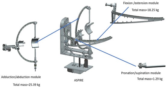
Figure 3.
ASPIRE rehabilitation modules.
To analyze the dynamic behavior of each rehabilitation module a harmonic motion was used as input for each active revolute joint (Amplitude: 50°, Frequency: 100 °/s) and the recorded torques of each joint are graphically represented. To achieve more accurate results, a simulated manikin was used during the simulation. For computing the biomechanical model of the patient Plagenhoef model [38] was used which defines standard man and women limb segments weights. The values for the upper limb extracted from [38] are given in Table 2.
Table 2.
Weight of upper-limb segment according to Plagenhoef [39].
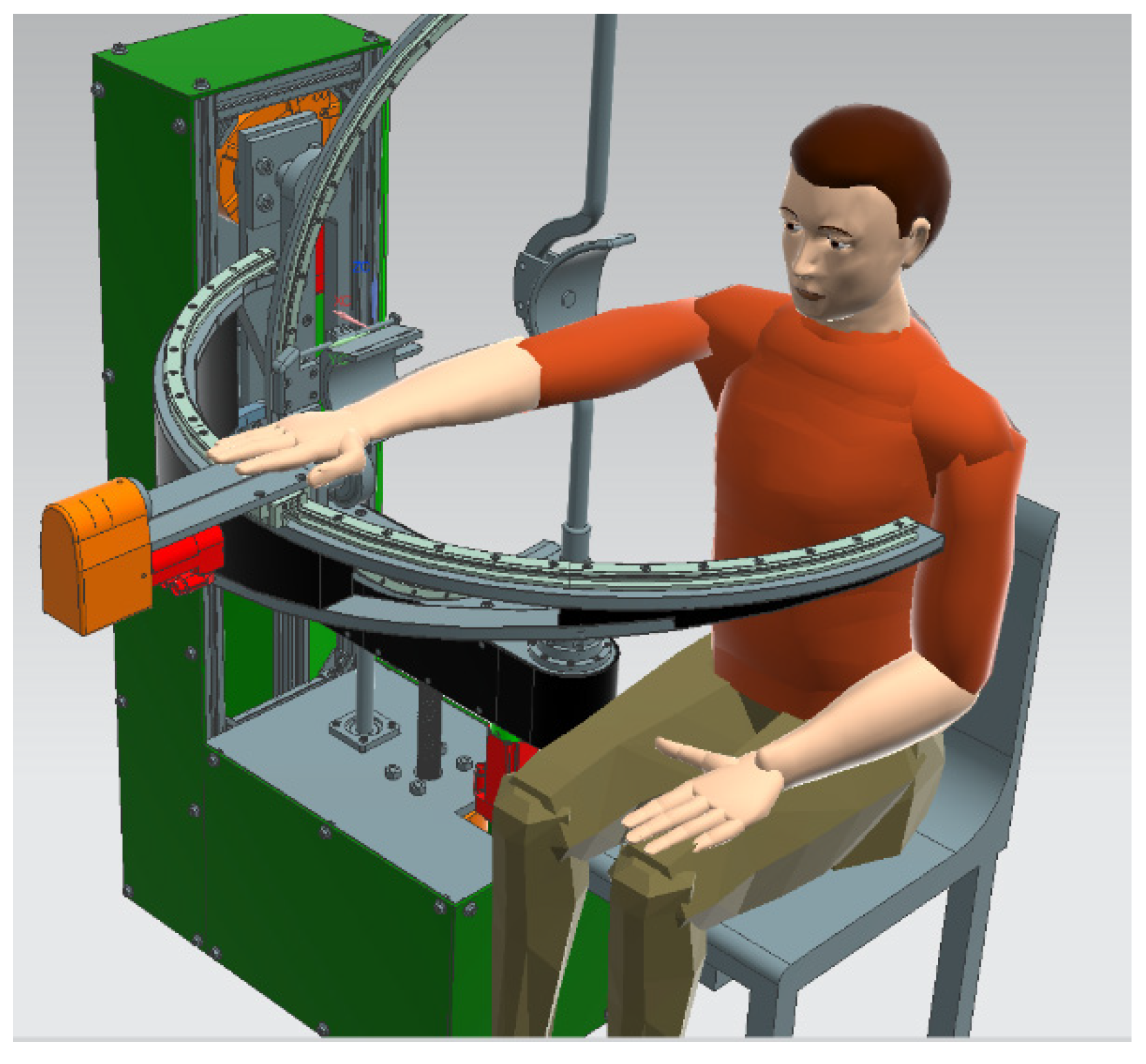
For the virtual simulation max value of segments weights was used for each upper-limb segment (0.526 kg for hand weight, 1.519 kg for forearm segment, and 2.633 kg for upper arm segment); the virtual setup is displayed in Figure 4.

Figure 4.
Virtual setup for simulation.
The virtual manikin was defined using the above data and the position of the patient during the procedure was simulated.
For the flexion-extension module, a 25-s simulation was carried on and the max torque obtained was 127.202 Nm while the minimum value was −13.231 Nm. Figure 5 represents the time-based torque variation during the simulation.
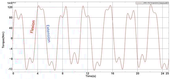
Figure 5.
Torques recorded during the flexion-extension module simulation.
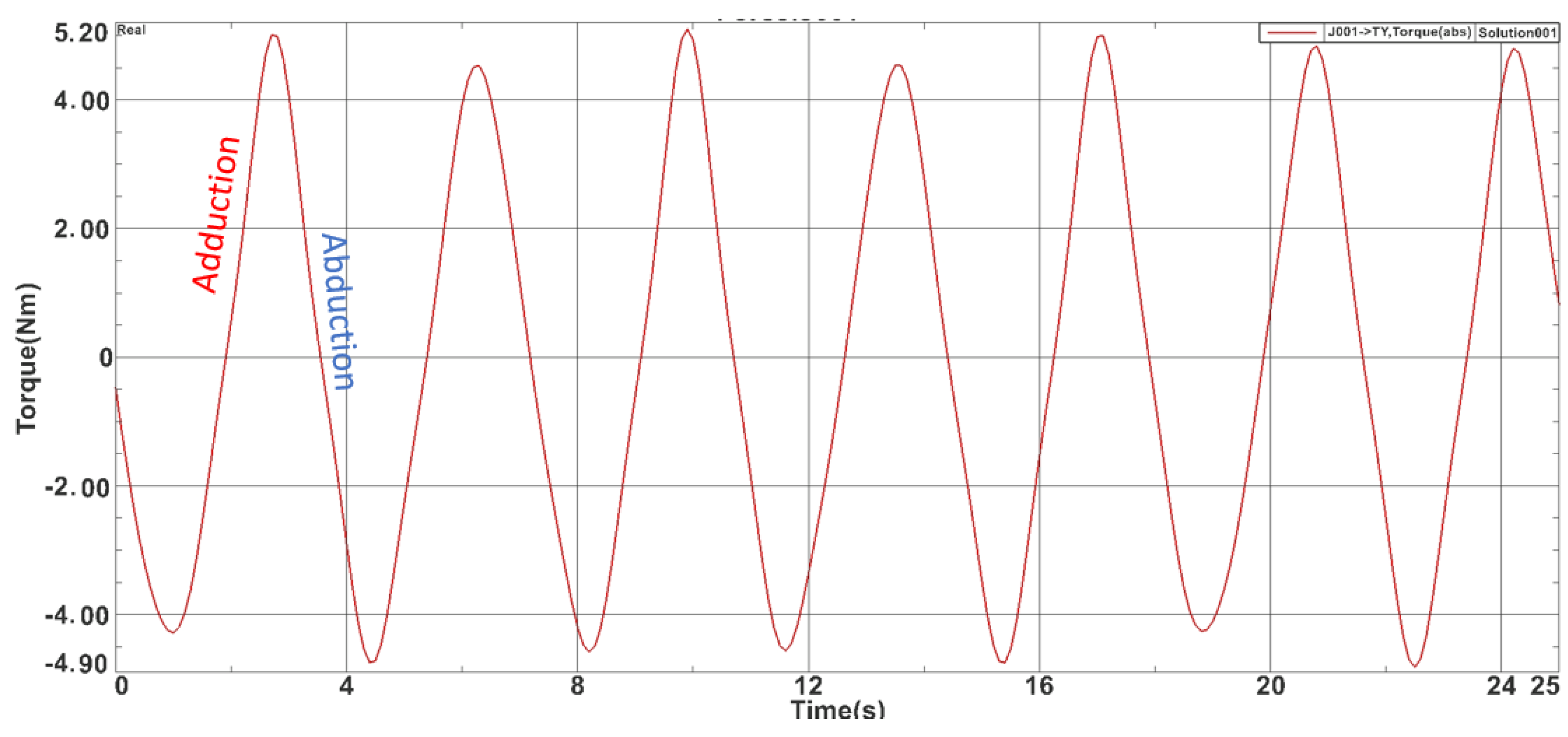
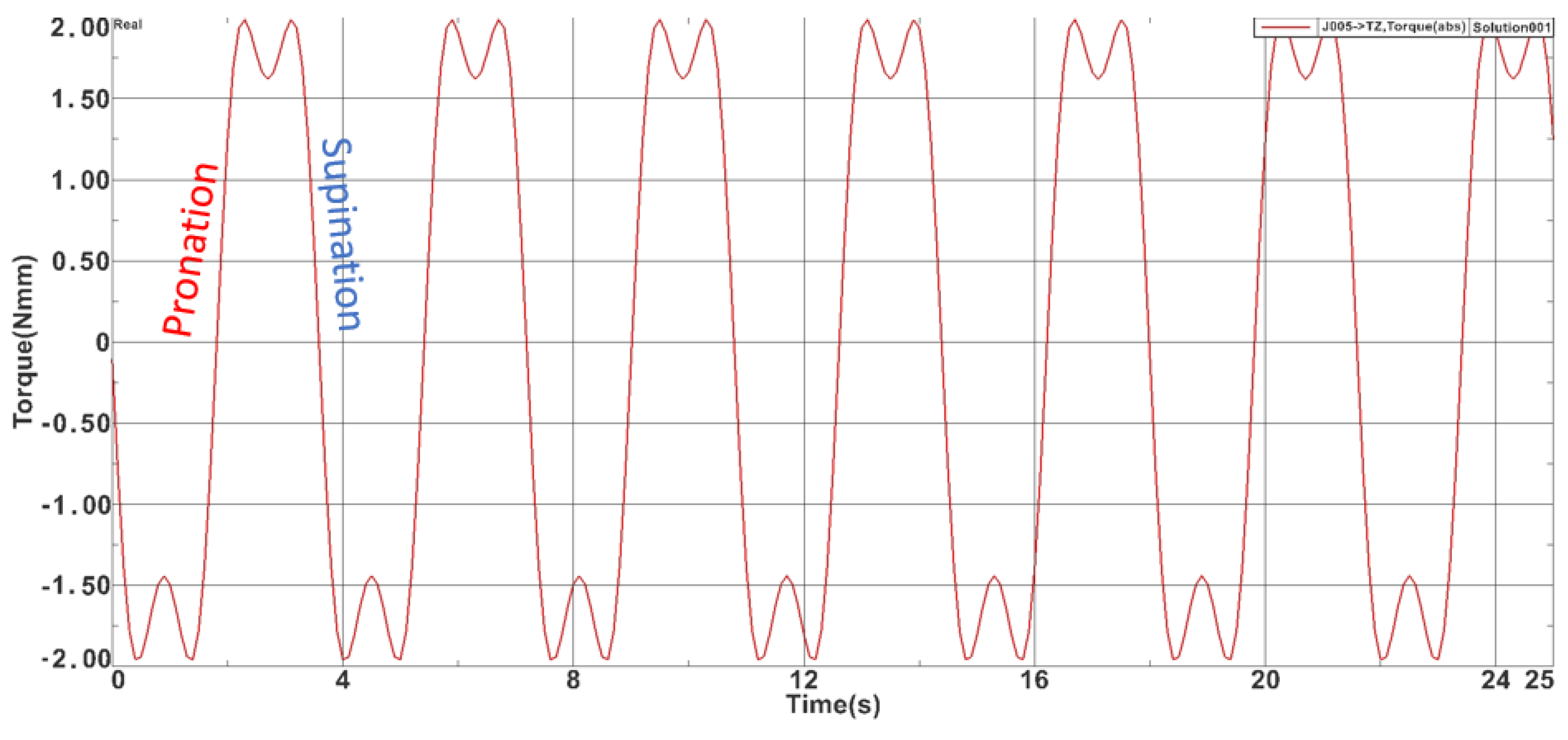
For the adduction-abduction module also a 25-s simulation was carried on and the max torque obtained was 5.040 Nm while the minimum value was −4.81 Nm. Figure 6 represents the time-based torque variation during the simulation. For the pronation-supination module the max torque obtained was 1.91 Nm while the minimum value was −1.89 Nm. Figure 7 represents the time-based torque variation during the simulation.
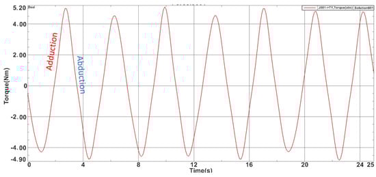
Figure 6.
Torques recorded during the adduction-abduction module simulation.
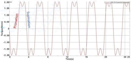
Figure 7.
Torques recorded during the pronation-supination module simulation.
The results obtained during the virtual simulation imply the use of quite big motors to perform the rehabilitation motion; to overcome this problem, gearboxes were used. For the flexion-extension mechanism a worm gearbox gear ratio I = 45:1 was used, for the adduction-abduction mechanism a planetary gearbox with gear ratio I = 100:1 was used, and for the pronation-supination mechanism a planetary gearbox with gear ration I = 11:1 was used.
After the proposed torque-controlled strategy has been implemented, a series of experimental runs are performed, and the values obtained are checked against the ones obtained via virtual simulation.
2.3. The Development of Torque Monitoring System
The need to monitor torque during the procedure came as a result of in-hospital tests performed on patients [39,40,41,42], where the ASPIRE succeeded in performing the required rehabilitation motion, but there were times when the operator had to manually stop the robotic system because the patient arm was unable to achieve the desired amplitude due to its spasticity.
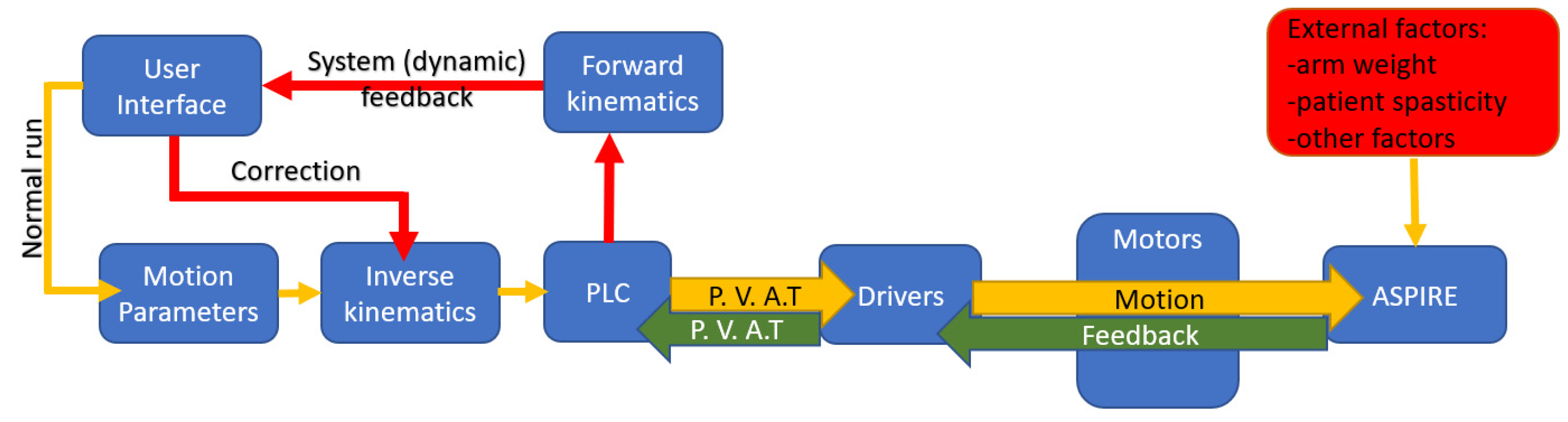
Figure 8 presents the dynamic control loop of the rehabilitation system. The functioning of the system is based on Normal Run sequence. In Normal Run, motion parameters (motion amplitudes, velocity, and number of repetitions) are given using the graphical user interface. Using inverse kinematics, data required for reaching the imposed amplitudes are transferred to the PLC which sends as inputs to the drivers the positions, velocities, accelerations, and a torque limit for the imposed motion (P.V.A.T). The drivers send the data to the motors and in exchange they read the state parameters of each motor (P.V.A.T.) and transmit the data to the PLC which provides dynamic feedback to the user. If there are differences between the data imposed via the Normal Run mode and those provided by the dynamic feedback, the system enters another state named Correction Run.
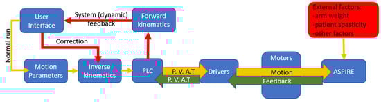
Figure 8.
Dynamic control loop (P.V.A.T. = Positions, Velocities, Accelerations, Torque).
The correction run is activated when torque monitor system identifies some irregularities in torque variation created by external factors. In this case the system signals the event and requires the physiotherapist interventions in fixing the problem.
When correction run is activated, the robotic system identified a disturbing external factor that affects the rehabilitation procedure. Different scenarios are required for this correction run based on the external factor type and the observation of the physiotherapist. After analyzing the risk factors from above, three scenarios have been developed (Figure 8):
- ✓
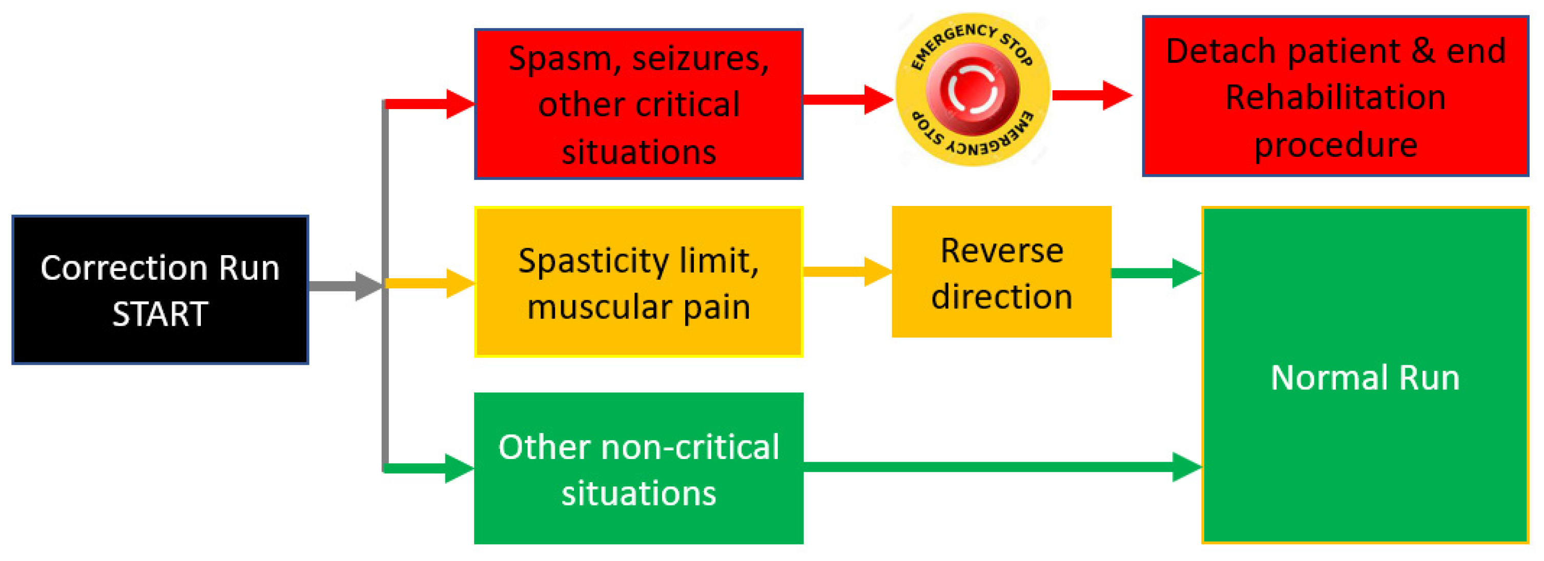
- The first scenario (Red scenario) implies spasm seizures or other critical situations that may endanger the patient. In this case the operator must press the emergency button and the patient is detached from the rehabilitation robot and primary care is administrated. The procedure may be resumed when the patient is in stable condition. This scenario is represented with red arrows and red blocks in Figure 9, and the output of this scenario is the end of the rehabilitation procedure due to unplanned events.
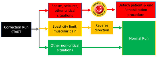 Figure 9. Actions following correction run event.
 - ✓
- The second scenario (Yellow scenario) includes reaching a spasticity limit or striving muscular pain. In this case, the system may return to the normal run after reversing direction. The system may re-enter the correction run mode when/if the spasticity limit is reached in the opposite direction. This scenario is represented with yellow arrows and yellow blocks in Figure 9 and the output of this scenario is Normal Run, the system that resumes the rehabilitation procedure until the next event.
- ✓
- The third scenario (Green scenario) is related to some non-critical situations (the patient rearranged his position, tremor, etc.). In this case the physiotherapist may resume the normal run. This scenario is represented with green arrows and green blocks in Figure 9, and the output of the scenario is also Normal Run, the system that resumes the rehabilitation motion until the next event.
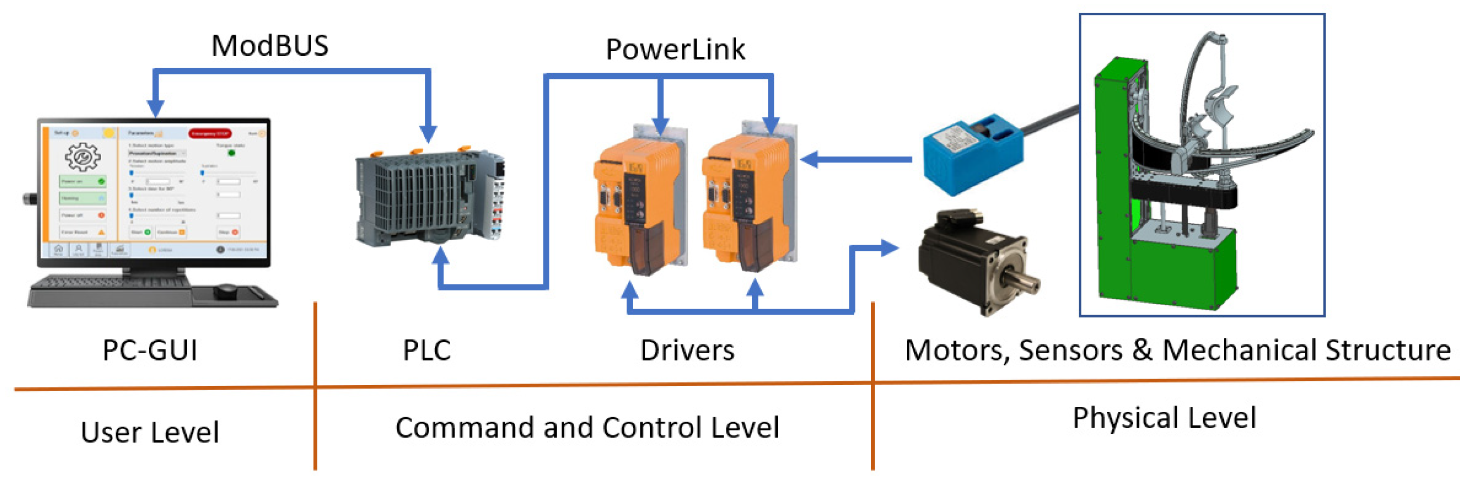
After developing the torque-monitoring strategy, the hardware architecture of the robotic system was reviewed, and the communication protocol was modified (old system used Virtual Network Connection while the new torque-monitoring system was based on Modbus protocol-required by the programming unit. In addition, the old interface was implemented in the PLC with the obvious limitations regarding graphical quality and extra functions (such as a database and exercise logging). The hardware configuration of the system is presented in Figure 10.
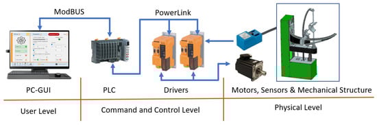
Figure 10.
Hardware configuration of the ASPIRE robot control system.
The components of the robotic system are divided into 3 levels. First level is the User Level, and it contains the graphical user interface (GUI) running on a PC and containing all the tools needed for inputting the rehabilitation parameters. The second level is the Command-and-Control Level, and it contains the Industrial PLC of the robotic system and the drivers required for controlling the motors of the robotic structure. The third level is the Physical Level, and it contains the motors required to drive the mechanical structure, the sensors needed for system initialization, and the mechanical structure of ASPIRE. The connection between the User Level and the Command-and-Control Level is made using Ethernet Cable and ModBus protocol, while the connection between the Command-and-Control Level and the Physical Level is made using special connector compatible with the drivers, motors, and sensors.
The entire process is coordinated using GUI that communicates with a PLC via ModBUS protocol. The PLC controls two drivers and each driver communicates with two servomotors and two proximity sensors. The communication between the drivers and servomotors is bidirectional; the driver communicates the required position and, at the same time, monitors the real-time position, velocity, acceleration, and torque recorded at the motor spindle. The communication between the sensors and the drivers is unidirectional from sensors to drivers. The sensors are used for system initialization. The process diagram for initialization is given in Figure 11.
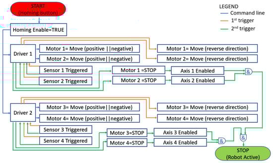
Figure 11.
Homing process flowchart.
After receiving the initialization command (Homing Button and blue arrows in Figure 11) each driver starts the assigned motors in positive or negative direction until the proximity sensors are triggered. When a sensor is triggered for the first time after the robot start-up (orange arrow in Figure 11), after receiving the rising edge signal the driver reverses the moving directions (also orange arrows) of the motor until the sensor is triggered again (green arrow in Figure 11). After the second rising edge signal the motion of the motor is stopped, and the axis is considered initialized (Axis is enabled). The operator may use the robotic system only after all axes (1 ÷ 4) are enabled. If the initialization of all axes is complete the system will signal the operator using a green LED placed in the GUI, and if there is an error and the initialization could not be completed, the LED color will turn red, and the error message is prompted for the user.
For implementing the torque monitoring system, Automation Studio [43] was used. The programming environment allows easy assembly of instructions for controlling the servo motors of the robotic structure using embedded functions tested in industrial environment, proving the stability of the control system. For easy integration of torque monitoring, Mapp Motion is used, a tool provided by B&R [43] that allows easy access to the parameters of the axes and at the same time enables the torque control for the motors.
2.4. Experimental Setup and Torque Control Validation
After the development of the torque-monitoring system, a series of in-lab tests were performed to validate the improved control system after receiving ethical approval to carry out the experiments. Ten healthy subjects were selected for the experiments from the research center staff and the experimental setup was defined.
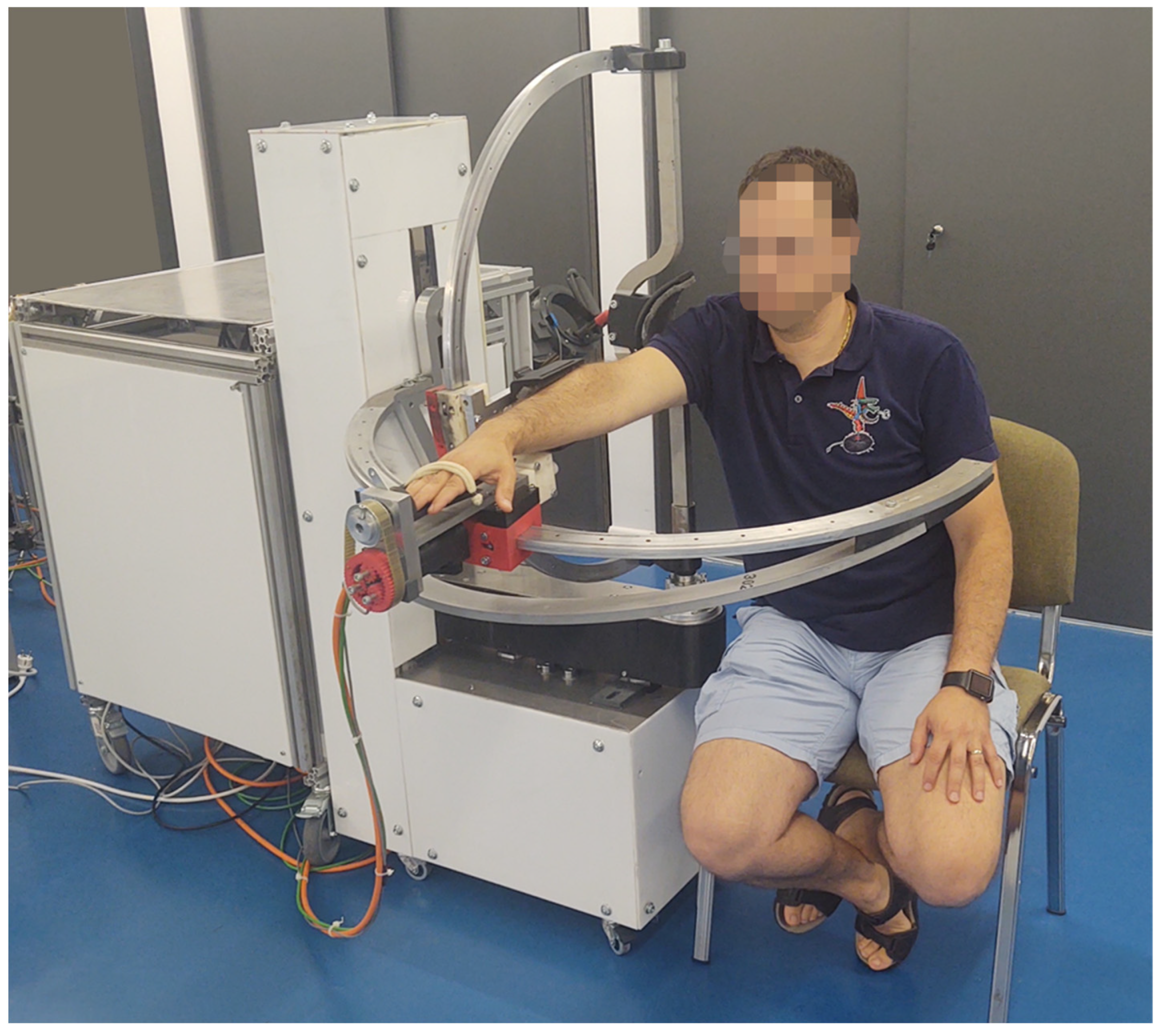
Figure 12 presents the ASPIRE robot placed in CESTER research center within Technical University of Cluj-Napoca for performing experimental tests. The robotic structure is physically attached to the control unit and because the participants in the experiment were healthy subjects and the main objective of the experiment was to validate the torque-monitoring system, a regular chair was used (during the previous tests performed in the hospital the patients were carried to the rehabilitation system using a wheelchair).
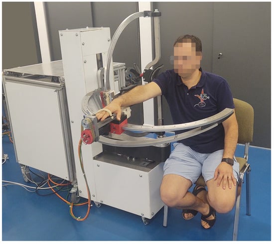
Figure 12.
ASPIRE experimental model.
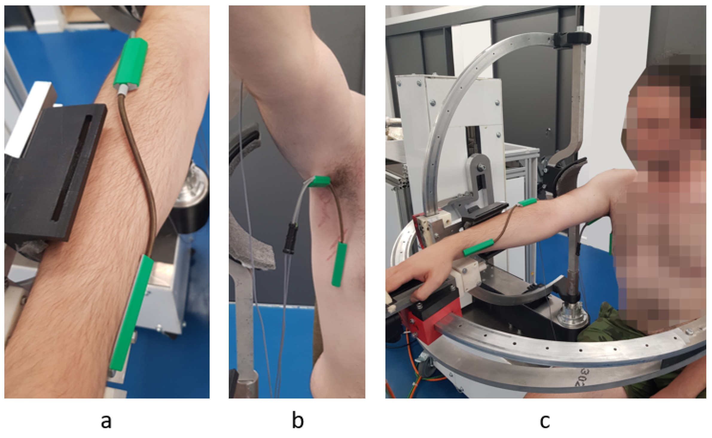
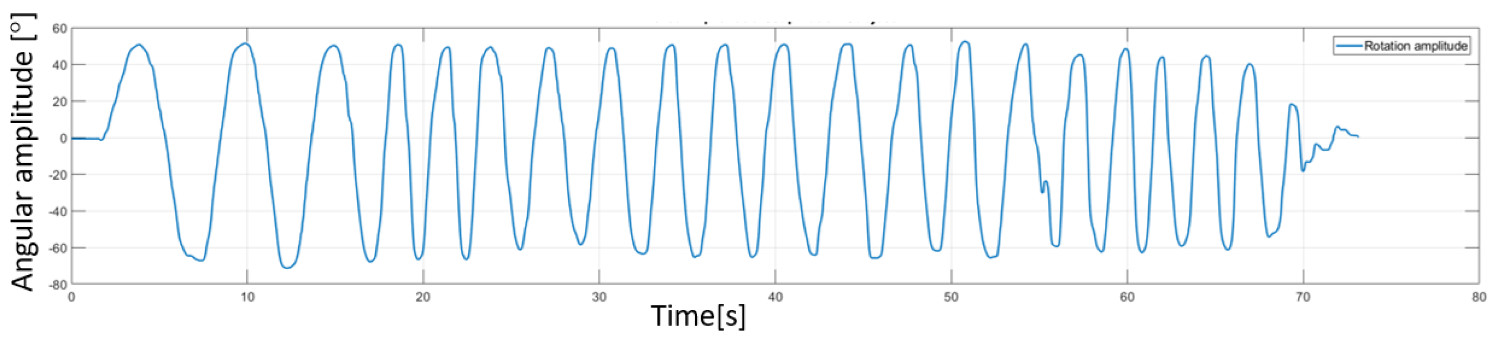
Besides the robotic system, a sensor system was used (Biometrics [44]). The sensor system uses a series of goniometers to simultaneously measure the angles in up to two planes of movement. During the experimental tests two goniometers were used. One was placed under the armpit of the subject to measure angles in two directions (flexion/extensions and adduction/abduction of the shoulder) and the other one was placed on the forearm of the subject to measure the rotation of the wrist with respect to the forearm (pronation/supination of the forearm). The decision to place the goniometers in this position came after a series of tests that revealed the optimal position to obtain most accurate reading during the rehabilitation motion. An image regarding this aspect of the experimental test is shown in Figure 13 along with a figure of the subject performing shoulder rehabilitation using the ASPIRE system. The amplitudes recorded by the biomedical sensors were not passed to the control system of the robot; the sensor system uses a separate graphical interface to calibrate each goniometer, and, after the calibration, the time-based variation of the amplitudes is graphically represented. The calibration of each goniometer is performed before placing the sensors on the patient by placing both ends of the goniometers on the same plane surface at the same time and pressing the interface “Calibrate” button. The entire calibration procedure for each goniometer takes up to 15 s. Each goniometer can read values between ±180 degrees with an accuracy of ±2 degrees measured over a range of 90 degrees and a repeatability of ±1 degree measured over a range of 90 degrees. The advantage of the system is given by the 12 h lasting battery and the wireless range up to 30 m. An example of the output of the sensor system for the pronation/supination motion is presented in Figure 14. The graph shows the rotation amplitudes recorded during a 20-repetitions session using a 50 degrees amplitude for pronation and 50 degrees amplitude for supination.

Figure 13.
Goniometer used for measuring the pronation supination (a) Torsiometer used for measuring the pronation/supination of the forearm (b) Goniometer used for measuring adduction/abduction/flexion/extension for the shoulder; (c) the subject’s position during the in-lab experimental tests.
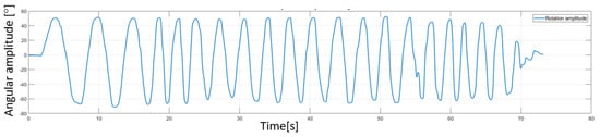
Figure 14.
Amplitudes recorded using Biometrics sensor system for a pronation/supination rehabilitation session.
Classical rehabilitation protocol, previously used for the tests performed in the hospital, was also used for performing the in-lab experimental test. The subject was sitting on the rehabilitation chair with the shoulder resting in the shoulder plate. The forearm was attached to the forearm anchor device, and his palm was supported by the palm support. Using the GUI of the robotic system, motion amplitudes were introduced for each rehabilitation motion. While the robotic system was performing the motion, a background thread was used to monitor the torque. During this stage of the experimental test, the goniometers were used only for validating the motion amplitudes given within the user interface. Each of 10 healthy subjects received the same treatment, meaning the same motion amplitudes (maximum amplitudes), the same velocity during the rehabilitation, and the same number of repetitions. In addition, each subject performed the rehabilitation two times, the first time letting the robotic system perform the entire motion and the second time trying to move against the rehabilitation motion to create excessive torque in the system. The obtained results are furthermore analyzed in the following sections.
3. Results
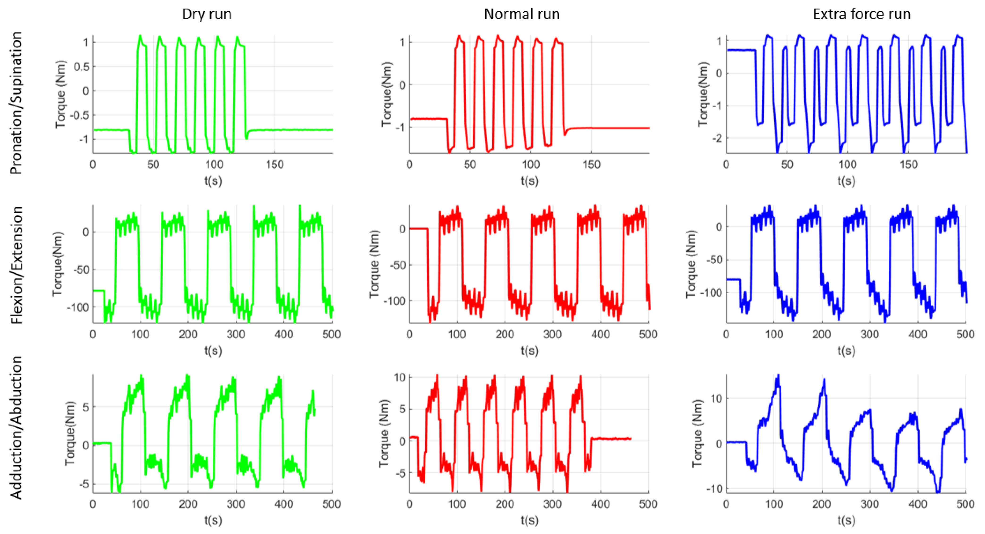
After performing the experimental tests with the healthy subjects, a supplementary dry run was made in order to establish the torques in the system when it is moving without any patient performing the rehabilitation. Figure 15 graphically represents the data recorded during the experimental test, which are then statistically analyzed. Median values from all runs were extracted and graphically represented using MatLab [45]. The first column of plots from Figure 15 represents the dry run test performed at the end of the experimental tests. These results should be similar to the ones obtained during the virtual simulation performed in the previous section of the paper and, as it can be seen, there are inconsistent differences between the results of the virtual simulation and the ones obtained using the experimental model. Table 3 summarizes the comparison between these data. The second column of plots represents the median values obtained during the experimental test, when the subject was creating no extra forces in the system. The third column represents the median values obtained when the subject of the experiment was opposing the rehabilitation motion. As it can be observed, there are some differences in the pronation/supination module. The maximum absolute value obtained is 1.10 Nm for the dry run test, 1.62 Nm for normal run test, and 2.45 Nm for the resisting test. There are also a series of differences in the flexion/extension module but it is not easy to identify them on the graphical representation. The maximum value obtained during the dry run test was 122 Nm, 131.39 Nm during the normal run, and 147.37 Nm during the resisting tests. Regarding the adduction/abduction module the maximum obtained value is 9.20 Nm for the dry run test, 10.47 Nm for the normal run, and 14.40 Nm for the resisting test.
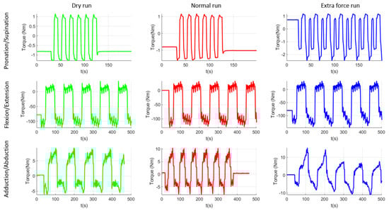
Figure 15.
Graphical representation of the experimental tests’ results.
Table 3.
Torque analysis results.
The values that resulted from the torque analysis are quite similar. There are some differences between different running modes but torque variation between different functioning modes is quite visible. The values obtained during the virtual simulation are just for checking the similarity of the constructive model with the experimental model. The differences between these two simulations are given by the imperfect homogeneity of the material, the manufacturing imperfections, the machining accuracy, the elasticity of material, and other material properties, but overall the values are correlated. Regarding the values obtained using the experimental model, a 47% torque difference was recorded between the dry run and normal run and 51% between the dry run and resisting test in the case of pronation -supination motion. For the flexion-extension motion the percentual difference was 7% between dry run and normal run and 12% between normal run and resisting test. Given the length of the moving element (almost 500 mm radius from origin) the force arm is quite big, and any load can create supplementary torques for the motor. For the adduction/abduction motion there was a 13% difference between the dry run and normal run and 37% difference between the normal run and resisting test, the difference also given by the geometry of the moving element, making it easy to increase the force arm applied on the motor. The trigger for the correction run may be set by the operator either to a given torque or to a certain percentual overpass.
In previous clinical trials feedback coming from the physiotherapists has helped the authors in optimizing the robotic system in terms of mechanical structure (aesthetics and functionality) and of control of the robotic system. All the optimizations in the end have the great target to increase the safety of the patient and the acceptance of the robotic system by the patient and by the personal operating the robotic system. As a result, the robotic system must comply with a series of requests to fulfill the needs of the clinician and to increase the trust of the patient (and physiotherapist) in the rehabilitation system. By unifying the control system of the robot with the biomedical sensor system (after proofing the feasibility of the sensors system also with the help of the physiotherapists), a complete system can be obtained to help the physiotherapist (the system allows user data registration and with the help of the goniometers the baseline assessment may be performed easily; the manual evaluation of the patient is time consuming, while using biomedical sensors can be performed in a few minutes). Using a user database to store all data for a specific user, a personalized rehabilitation procedure may be provided for each patient by evaluating the evolution or regression of the patient through user database reports delivered at the end of each rehabilitation session.
4. Discussion
After analyzing the results obtained at the end of the experimental tests, the torque-monitoring system was validated. The system performed accordingly, and no events were reported during the experimental runs. The system was able to record the torques during the entire rehabilitation procedure and a special section was implemented in the user interface to show torque variation during the rehabilitation using a code of colors (green for normal run and yellow for when the torque is not normal, but it is in allowable limits, and red for when the torque in the system exceeds a certain imposed value). The allowable torque for each patient is established by the physiotherapist after the first general evaluation of the patient using a series of dynamometers to test the spasticity of the patient and the ability to perform a certain motion.
Using the Biometrics sensors, the rehabilitation system may be also used as an evaluation device. The robotic system is able to perform “blind” rehabilitation. Using this feature, after the general health assessment of the patient by the physiotherapist, ASPIRE may be used to measure the spasticity level of the patient. The goniometers are placed on the patient body in the previously identified areas (Section 2.4). After calibrating the sensors, the patient is placed in the rehabilitation system and prepared for the rehabilitation procedure. In the user interface maximum amplitudes for rehabilitation motion are introduced and the torque monitor system is started. The speed of the rehabilitation motion is set to lowest, and the number of repetitions is set to 1. After the robotic system starts to perform the rehabilitation motion, the sensor system records the real-time amplitude of the motion performed, and the torque is monitored within the allowable limits. If the system succeeds in performing the entire motion without triggering the torque monitor, then the patient has no spasticity, but if the torque monitor is triggered then the spasticity degree of the patient is computed using the value given by the sensor measuring system. This value can be used as a starting point for the future rehabilitation sessions and after each session this value can be tested to see if there are some improvements.
Torque monitor can be a useful tool to test some of the effects of some neurological diseases. For example, if after rehabilitation, graphical results show regular variation that can be interpreted as noise, further analysis may reveal that the noise is caused by the patient’s tremor.
Based on the success of the experimental tests, and on the feedback received during the experimental tests from both the subject and from the robotic system, the functionality of the improved control system was validated. The system is able to accurately monitor the torques from the system using only the encoder of the servomotors without using any additional sensors for torque monitoring. The obtained values were checked against the values that resulted from the virtual simulation of the system and the differences were within an allowable range, the differences caused by the structure of the material, density, and even the manufacturing of some components.
Future work targets the implementation of interactive user interface using human–robot interaction modalities in order to prepare the robotic system for another session of clinical trials for the fall of 2021.
5. Conclusions
Torque monitoring system was successfully implemented in the control of the ASPIRE robotic system. The development of the system started from the requests identified during the clinical trials performed in the fall of 2019 in Cluj-Napoca. A series of effects that may influence the effectiveness of the rehabilitation were presented and torque control proved to be a solution in identifying and overcoming some of these effects. After the development of the torque control system the performance was tested using healthy subjects chosen among the staff of the research center. The results have validated the functionality of the proposed improved control system and pushed the development of the experimental model towards the next level of maturity, preparing it for further clinical trials. At the same time the torque-based control adds to patient safety and the possibility to improve the HRI characteristics of the robotic system with high levels of safety and user-friendliness.
Author Contributions
Conceptualization, D.P., P.T., C.V., G.B. and G.C.; Data curation, D.T., N.T., I.D.G. and C.A.; Formal analysis, N.P.; Investigation, D.T., P.T., N.T., C.V., I.D.G., G.B., C.A. and G.C.; Methodology, I.D.G., G.B., G.C. and N.P.; Project administration, D.P.; Resources, D.T.; Software, G.B.; Validation, C.V.; Writing—original draft, D.P. and P.T.; Writing—review and editing, P.T. All authors have read and agreed to the published version of the manuscript.
Funding
This work was supported by a grant from the Romanian Ministry of Research and Innovation, CCCDI—UEFISCDI, project number PN-III-P2-2.1-PED-2019-3022/546PED/2020 (NeuroAssist) within PNCDI III, and by the project POCU/380/6/13/123927—ANTREDOC, “Entrepreneurial competencies and excellence research in doctoral and postdoctoral studies programs”, co-funded from the European Social Fund through the Human Capital Operational Program 2014–2020.
Institutional Review Board Statement
Ethical review and approval were waived for this study, due to the fact that the validation tests were intended only to assess the feasibility and range of motion of ASPIRE for the rehabilitation of the upper limb, being achieved in laboratory conditions, which required the participation of volunteers, healthy subjects. Furthermore, the volunteers have given their written consent after being informed about the test circumstances and the robotic system’s operation, as well as any hazards or safety concerns that may arise during the tests.
Informed Consent Statement
Informed consent was obtained from all subjects involved in the study.
Data Availability Statement
The data presented in this study are openly available in reference number [37,39,40,41].
Conflicts of Interest
The authors declare no conflict of interest.
References
- Healthline. Available online: https://www.healthline.com/health/monoplegia (accessed on 15 July 2021).
- Garcia, R.V. The Brachial and Crural Indices of Modern North American Population. Master’s Thesis, Texas State University, San Marcos, TX, USA, 2015, unpublished. [Google Scholar]
- Iqbal, J.; Bruno, A.; Berger, M. Stroke causing pure brachial monoparesis. J. Stroke Cerebrovasc. Dis. 1995, 5, 88–90. [Google Scholar] [CrossRef]
- Department of Economic and Social Affairs. World Population Ageing 2017 Highlights; United Nations: New York, NY, USA, 2017. [Google Scholar]
- Eyigor, S.; Durmaz, B.; Karapolat, H. Monoparesis with complex regional pain syndrome-like symptoms due to brachial plexopathy caused by varicella zoster virus: A case report. Arch. Phys. Med. Rehabil. 2006, 87, 1653–1655. [Google Scholar] [CrossRef] [PubMed]
- NHS Funding. Available online: https://nhsfunding.info/ (accessed on 15 July 2021).
- Baniqued, P.D.E.; Stanyer, E.C.; Awais, M.; Alazmani, A.; Jackson, A.E.; Mon-Williams, M.A.; Mushtaq, F.; Holt, R.J. Brain–computer interface robotics for hand rehabilitation after stroke: A systematic review. J. Neuroeng. Rehabil. 2021, 18, 1–25. [Google Scholar] [CrossRef] [PubMed]
- Gull, M.A.; Thoegersen, M.; Bengtson, S.H.; Mohamadi, M.; Struijk, L.N.S.A.; Moeslund, T.B.; Bak, T.; Bai, S. A 4-DOF upper limb exoskeleton for physical assistance: Design, modeling, control and performance evaluation. Appl. Sci. 2021, 11, 5856. [Google Scholar] [CrossRef]
- Chaparro-Rico, B.D.M.; Cafolla, D.; Castillo-Castaneda, E.; Ceccarelli, M. Design of arm exercises for rehabilitation assistance. J. Eng. Res. 2020, 8, 204–218. [Google Scholar] [CrossRef]
- Li, J.; Cao, Q.; Dong, M.; Zhang, C. Compatibility evaluation of a 4-DOF ergonomic exoskeleton for upper limb rehabilitation. Mech. Mach. Theory 2021, 156, 104146. [Google Scholar] [CrossRef]
- Kim, B.; Deshpande, A.D. An upper-body rehabilitation exoskeleton Harmony with an anatomical shoulder mechanism: Design, modeling, control, and performance evaluation. Int. J. Robot. Res. 2017, 36, 414–435. [Google Scholar] [CrossRef]
- Brahmi, B.; Driscoll, M.; El Bojairami, I.K.; Saad, M.; Brahmi, A. Novel adaptive impedance control for exoskeleton robt rehabilitation using a nonlinear time-delay disturbance observer. ISA Trans. 2021, 108, 381–392. [Google Scholar] [CrossRef]
- Paolucci, T.; Agostini, F.; Mangone, M.; Berneti, A.; Pezzi, L.; Liotti, V.; Recubini, E.; Cantarella, C.; Bellomo, R.G.; D′Azurio, C.; et al. Robotic rehabilitation for end-effector device and botulinum toxin in upper limb rehabilitation in chronic post-stroke patients: An integrated rehabilitative approach. Neurol. Sci. 2021. [Google Scholar] [CrossRef]
- DeBoon, B.M.; Foley, R.C.A.; Nokleby, S.B.; La Delfa, N.J.; Rossa, C. Nine degree-of-freedom kinematic modeling of the upper-limb complex for constrained workspace evaluation. J. Biomech. Eng. 2021, 143, 1–13. [Google Scholar] [CrossRef]
- Vaida, C.; Carbone, G.; Major, K.; Major, Z.; Plitea, N.; Pisla, D. On human robot interaction modalities in the upper limb rehabilitation after stroke. Acta Tech. Napoc. Ser. Appl. Math. Mech. Eng. 2017, 60, 91–102. [Google Scholar]
- Motos, A.B.; Blanco, A.; Badesa, F.J.; Barios, J.A.; Zollo, L.; Garcia-Aracil, N. Human arm joints reconstruction algorithm in rehabilitation therapies assisted bt end-effector robotic devices. J. Neuroeng. Rehabil. 2018. [Google Scholar] [CrossRef] [Green Version]
- Zhang, L.; Guo, S.; Sun, Q. Development and assist-As-needed control of an end-effector upper limb rehabilitation robot. Appl. Sci. 2020, 10, 6684. [Google Scholar] [CrossRef]
- Vaida, C.; Pisla, D.; Schadlbauer, J.; Husty, M.; Plitea, N. Kinematic analysis of an innovative medical parallel robot using study parameters. In New Trends in Medical and Service Robots. Mechanisms and Machine Science; Wenger, P., Chevallereau, C., Pisla, D., Bleuler, H., Rodić, A., Eds.; Springer: Cham, Switzerland, 2016; Volume 39, Available online: https://doi.org/10.1007/978-3-319-30674-2_7 (accessed on 10 July 2021). [CrossRef]
- Vaida, C.; Plitea, N.; Gherman, B.; Szilaghyi, A.; Galdau, B.; Cocorean, D.; Covaciu, F.; Pisla, D. Structural analysis and synthesis of parallel robots for brachytherapy. In New Trends in Medical and Service Robots. Mechanisms and Machine Science; Pisla, D., Bleuler, H., Rodic, A., Vaida, C., Pisla, A., Eds.; Springer: Cham, Switzerland, 2014; Volume 16, Available online: https://doi.org/10.1007/978-3-319-01592-7_14 (accessed on 10 July 2021). [CrossRef]
- Pisla, D.; Plitea, N.; Gherman, B.G.; Vaida, C.; Pisla, A.; Suciu, M. Kinematics and design of a 5-DOF parallel robot used in minimally invasive surgery. In Advances in Robot Kinematics: Motion in Man and Machine; Lenarcic, J., Stanisic, M., Eds.; Springer: Dordrecht, The Netherlands, 2010; Available online: https://doi.org/10.1007/978-90-481-9262-5_11 (accessed on 10 July 2021). [CrossRef]
- Schonstein, C. Considerations about matrix exponentials in geometrical modeling of the robots. Acta Tech. Napoc. Ser. Appl. Math. Mech. Eng. 2019, 62, 337–342. [Google Scholar]
- Schonstein, C. Kinematic control functions for a serial robot structure based on the time derivative Jacobian matrix. Acta Tech. Napoc. Ser. Appl. Math. Mech. Eng. 2018, 61, 219–224. [Google Scholar]
- Nedezki, C.M. Position problem for 3rpr 3-mobile plan parallel manipulator. Acta Tech. Napoc. Ser. Appl. Math. Mech. 2013, 56, 317–322. [Google Scholar]
- Zhao, F.; Yang, Z.; Li, Z.; Gua, D.; Li, H. Extract executable action sequences from natural language instructions based on DQN for medical service robots. Int. J. Comput. Commun. Control 2021, 16. [Google Scholar] [CrossRef]
- Escalante, F.M.; Jutinico, A.L.; Jaimes, J.C.; Terra, M.H.; Siqueira, A.A.G. Markovian robust filtering and control applied to rehabilitation robotics. IEEE/ASME Trans. Mechatron. 2021, 26. [Google Scholar] [CrossRef]
- Kim, D.; Lee, J. Robust control of a system with pneumatic spring. J. Frankl. Inst. 2021, 358, 555–574. [Google Scholar] [CrossRef]
- Masengo, G.; Zhang, X.D.; Yin, G.; Alhassan, A.B.; Dong, R.L.; Orban, M.; Mudaheranwa, E. A design of lower limb rehabilitation robot and its control for passive training. In Proceedings of the 10th Institute of Electrical and Electronics Engineers International Conference on Cyber Technology in Automation, Control, and Intelligent Systems (IEEE-CYBER 2020), Xi’an, China, 10–13 October 2020; pp. 152–157. [Google Scholar]
- Antal, T.A. Addendum modification of spur gears with equalized efficiency at the points where the meshing starts and ends. Mechanika 2016, 6, 480–485. [Google Scholar]
- Antal, T.A.; Antal, A. The use of genetic algorithms for the design of mechatronic transmission with improved operating conditions. In Proceedings of the 3rd International Conference on Human System Interaction, Rzeszow, Poland, 13–15 May 2010. [Google Scholar] [CrossRef]
- Aliabadi, M.; Mashayekhifard, J.; Moha, B. Intelligent and classic control of rehabilitation robot with robust PID and Fuzzy methods. Majlesi J. Mechatron. Syst. 2020, 9, 31–36. [Google Scholar]
- Bouteraa, Y.; Abdallah, I.B.; ElMogy, A.; Tariq, U.; Ahmad, T. A fuzzy logic architecture for rehabilitation robotic systems. Int. J. Comput. Commun. Control. 2020, 15, 1–17. [Google Scholar] [CrossRef]
- Lyu, S.; Cheah, C.C. Human-robot interaction control based on a general energy shaping method. IEEE Trans. Control Syst. Technol. 2020, 28, 2445–2460. [Google Scholar] [CrossRef]
- Shi, D.; Zhang, W.X.; Zhang, W.; Ju, L.H.; Ding, X.L. Human-centered adaptive control of lower limb rehabilitation robot based on human-robot interaction dynamic. Mech. Mach. Theory 2021, 162. [Google Scholar] [CrossRef]
- Bouteraa, Y.; Ben Abdallah, I.; Alnowaiser, K.; Ibrahim, A. Smart solution for pain detection in remote rehabilitation. Alex. Eng. J. 2021, 60, 3485–3500. [Google Scholar] [CrossRef]
- Erwin, A.; McDonald, C.G.; Moser, N.; O′Malley, M.K. The SE-AssessWrist for robot-aided assessment of wrist stiffness and range of motion: Development and experimental validation. J. Rehabil. Assist. Technol. Eng. 2021, 8. [Google Scholar] [CrossRef]
- Vaida, C.; Plitea, N.; Pîslă, D.; Carbone, G.; Gherman, B.; Ulinici, I.; Pislă, A. Spherical Robot for Medical Recovery of Upper Limb Proximal Area. Patent RO132233-A0, 29 November 2017. [Google Scholar]
- Tucan, P.; Plitea, N.; Vaida, C.; Gherman, B.; Carbone, G.; Luchian, I.; Pisla, D. Inverse dynamics and simulation of a parallel robot used in shoulder rehabilitation. In New Trends in Mechanism and Machine Science. EuCoMeS 2020. Mechanisms and Machine Science; Pisla, D., Corves, B., Vaida, C., Eds.; Springer: Cham, Switzerland, 2020; Volume 89. [Google Scholar]
- Plagenhoef, S.; Gaunor, E.V.; Abdelnour, T. Anatomical data for analyzinghuman motion. J. Res. Q. Exerc. Sport 1983, 54, 169–178. [Google Scholar] [CrossRef]
- Tucan, P.; Vaida, C.; Plitea, N.; Pisla, A.; Carbone, G.; Pisla, D. Risk-based assessment engineering of a parallel robot used in post-stroke upper limb rehabilitation. Sustainability 2019, 11, 2893. [Google Scholar] [CrossRef] [Green Version]
- Major, Z.Z.; Vaida, C.; Major, K.A.; Tucan, P.; Simori, G.; Banica, A.; Brusturean, E.; Burz, A.; Craciunas, R.; Ulinici, I.; et al. The impact of robotic rehabilitation on the motor system in neurological diseases. A multimodal neurophysiological approach. Int. J. Environ. Res. Public Health 2020, 17, 6557. [Google Scholar] [CrossRef]
- Tucan, P.; Vaida, C.; Ulinici, I.; Banica, A.; Burz, A.; Pop, N.; Birlescu, I.; Gherman, B.; Plitea, N.; Antal, T.; et al. Optimization of the ASPIRE spherical parallel rehabilitation robot based on its clinical evaluation. Int. J. Environ. Res. Public Health 2021, 18, 3281. [Google Scholar] [CrossRef]
- Vaida, C.; Ulinici, I.; Banica, A.; Burz, A.; Gherman, B.; Tucan, P.; Pisla, A.; Carbone, G.; Pisla, D. First clinical evaluation of a spherical robotic system for shoulder rehabilitation. In New Trends in Medical and Service Robotics; MESROB 2020. Mechanisms and Machine, Science; Rauter, G., Cattin, P.C., Zam, A., Riener, R., Carbone, G., Pisla, D., Eds.; Springer: Cham, Switzerland, 2020; Volume 93, Available online: https://doi.org/10.1007/978-3-030-58104-6_8 (accessed on 10 July 2021). [CrossRef]
- B&R Industrial Automation GmbH. Available online: https://www.br-automation.com/de/ (accessed on 21 July 2021).
- Biometrics Ltd. Available online: https://www.biometricsltd.com/ (accessed on 21 July 2021).
- MatLab. Available online: https://www.mathworks.com/ (accessed on 21 July 2021).


Publisher’s Note: MDPI stays neutral with regard to jurisdictional claims in published maps and institutional affiliations. |
© 2021 by the authors. Licensee MDPI, Basel, Switzerland. This article is an open access article distributed under the terms and conditions of the Creative Commons Attribution (CC BY) license (https://creativecommons.org/licenses/by/4.0/).