Abstract
Augmented reality medical training simulators can provide a realistic and immersive experience by overlapping the virtual scene on to the real world. Latency in augmented reality (AR) medical training simulators is an important issue as it can lead to motion sickness for users. This paper proposes a framework that can achieve real-time rendering of the 3D scene aligned to the real world using a head-mounted display (HMD). Model deformation in the 3D scene is categorised into local deformation derived from user interaction and global deformation determined by the simulation scenario. Target shapes are predefined by a simulation scenario, and control points are placed to embed the predefined shapes. Free-form deformation (FFD) is applied to multiple shapes to efficiently transfer the simulated model to the HMD. Global deformation is computed by blending a mapping matrix of each FFD with an assigned weighting value. The local and global deformation are then transferred through the control points updated from a deformed surface mesh and its corresponding weighting value. The proposed framework is verified in terms of latency caused by data transmission and the accuracy of a transmitted surface mesh in a vaginal examination (VE) training simulation. The average latency is reduced to 7 ms, less than the latency causing motion sickness in virtual reality simulations. The maximum relative error is less than 3%. Our framework allows seamless rendering of a virtual scene to the real world with substantially reduced latency and without the need for an external tracking system.
1. Introduction
Augmented reality (AR) has been increasingly used in medical applications [1,2,3] as technological advances have resulted in head-mounted displays (HMD) offering higher resolution, larger field-of-view, and increased onboard processing power [4]. AR-based medical training simulation involving visual and haptic interfaces has recently gained popularity and is expected to become a useful education tool in the future [5]. AR can increase the visual realism of conventional virtual reality (VR)-based medical training and reduce the cost and size of a medical simulator by replacing the physical exterior with an augmented virtual scene. There are many challenging issues that need to be addressed to successfully use AR in medical simulation. These include: registration error [6] of the augmented virtual scene onto the real world, synchronisation [7] between visual and haptic feedback, and distortion of haptic perception [8].
In medical training simulation, organ models are deformed by user interaction through simulated instruments or simulated hands or as part of the training scenario (e.g., dilation of the cervix over time during labour). User interaction is typically performed via a haptic interface able to provide touch feedback to the user. The resulting deformation needs to be displayed in real time on the HMD with synchronised haptic feedback. Existing AR HMDs cannot afford to compute organ deformation in real time because of the computational load. Therefore, the deformation must be computed on a separate computer, and the deformed organ model and instrument/hand must then be displayed on the HMD in real time. However, it might be difficult to transfer and render the updated simulation data on the HMD without latency. This will depend on the target medical simulation, the performance of the HMD, and the bandwidth of the network. A streaming-based method has been used to solve this problem for 3D visualisation on mobile devices [9] and 360° VR [10], by streaming images instead of rendering 3D objects on low-powered devices. A 3D scene taken by a specific virtual camera is converted to images and then transferred to the HMD. This can reduce both the amount of data transmission and the computational burden of rendering the 3D scene, but it is difficult to align the 3D object to the real world on the HMD as 2D images are transferred without depth information. Real-time tracking of a camera attached to the HMD can be used to generate images aligned to the real world on a PC [9,10,11,12], but this results in a high computational burden and the need for an external tracking system. As HMD technology advances, it becomes affordable and feasible to render the 3D scene to the real world by using a software developer kit (SDK) such as Vuforia on an HMD in real time. This paper proposes a framework that can achieve real-time rendering of the 3D scene aligned to the real world on an off-the-shelf AR HMD by reducing the amount of data transmitted whilst retaining all the necessary information for accurate and high-resolution 3D rendering. The proposed framework allows direct rendering of the transmitted mesh model on the HMD without having to track and send its position and orientation to the PC. The proposed framework is applied and verified on a medical training simulation of vaginal examination during labour.
2. Materials and Methods
2.1. Use Case-Simulation of Vaginal Examination During Labour
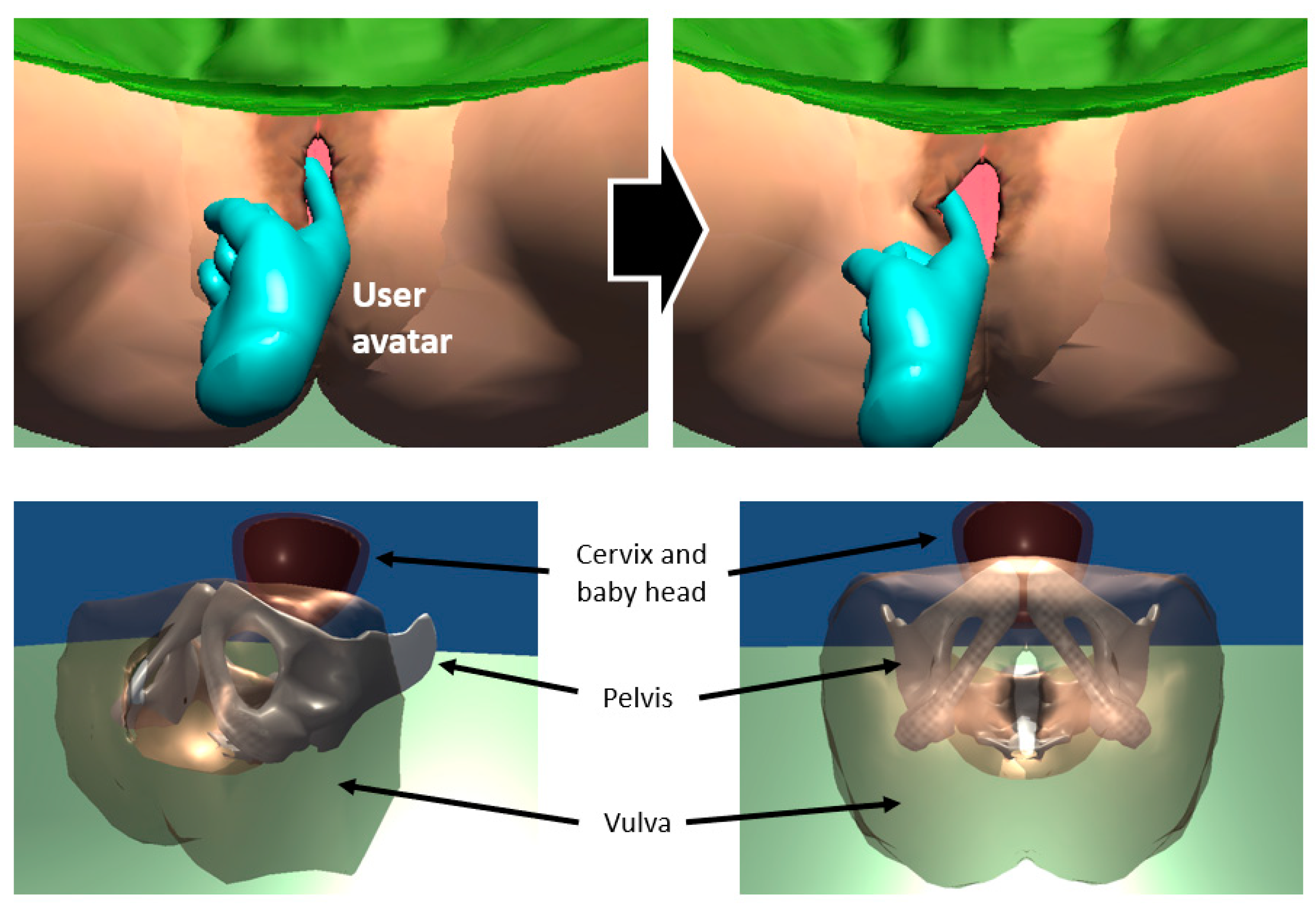
Vaginal examination (VE) is regularly performed during labour to determine its progression. Training is traditionally performed in real clinical scenarios, which can lead to an increase in the number of examinations performed and patient discomfort. Obstetricians and midwives need to learn the necessary skills to determine the progression of labour by using the sense of touch through their fingers as the vagina and cervix cannot be seen. Therefore, haptic feedback is crucial for training how to perform a VE. Researchers have used different simulation approaches to recreate real clinical scenarios [13,14]. The most representative training method is the use of mannequins, but they have limited training scenarios and durability issues due to their construction using silicon materials. AR-based training simulation of VE can compute the deformation of the vulva, cervix, and baby’s head based on a predefined scenario and user interaction, providing haptic and visual feedback accordingly through a bespoke haptic interface and HMD. Moreover, AR-based training simulation can visually overlap a pregnant woman onto a haptic interface to increase the realism of the simulation. Trainees can benefit from the intuitive augmented scene of the cervix and baby’s head (Figure 1, bottom) that are not visible in real scenarios. This paper applies the proposed multi-shape free-form deformation framework to a training simulator of VE during labour to demonstrate its use, verify the latency caused by data transmission and measure the accuracy of the transmitted mesh.
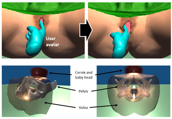
Figure 1.
Interaction between a user avatar and vulva model (top) and internal view (bottom) of a pregnant woman model in AR-based training simulation of vaginal examination.
2.2. Multi-Shape Free-Form Deformation (MSFFD)
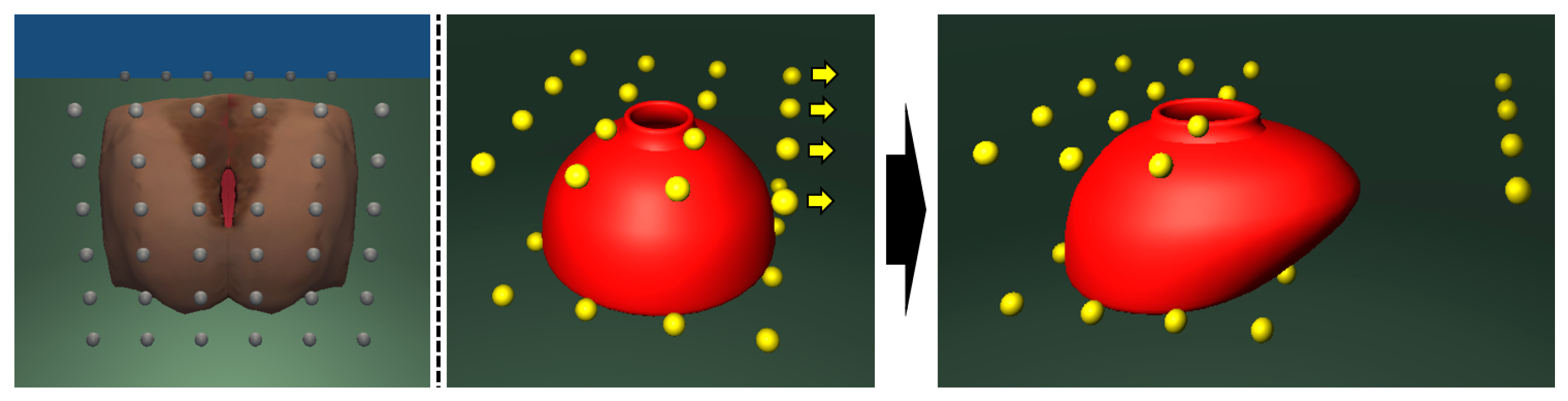
This paper uses free-form deformation (FFD) [15,16] to transmit the deformation of the vulva and cervix to the HMD. FFD has been widely used in the field of computer graphics to manipulate high-resolution meshes with a small number of control points. The target mesh is embedded in a lattice of control points, as shown in Figure 2. A mapping is defined between the control points and the surface. Surface vertices can be represented by a mapping matrix and a control points vector as shown in Equation (1).
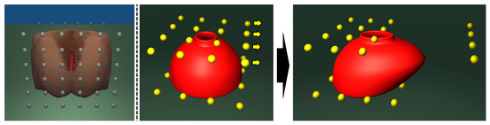
Figure 2.
Vulva mesh model (left) embedded in a lattice of control points (grey). Cervix mesh model (middle, red) embedded in a lattice of control points (yellow). Cervix mesh deformed by moving the control points (right).
Due to the compact nature of FFD, it is possible to substantially reduce the amount of data transmission to the HMD by delivering control points of the surface mesh instead of the surface mesh itself. The surface mesh is then reconstructed in the HMD from the received control points and a mapping matrix. The deformation of the surface mesh and corresponding haptic feedback are both computed in a server PC. Forces resulting from the interaction between the virtual instrument and the mesh are sent to a haptic device for producing haptic feedback. Control points are updated by an inverse mapping matrix and the deformed surface mesh. The inverse mapping matrix can be obtained in advance by the pseudo inverse, as shown in Equation (2).
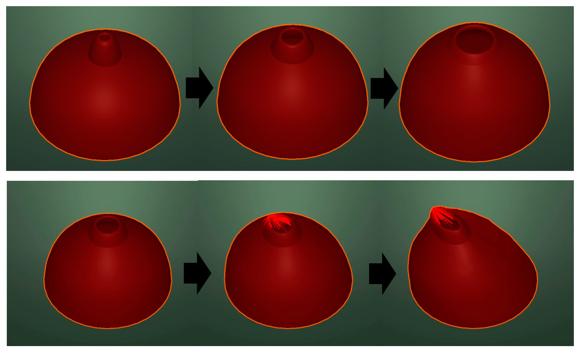
The surface mesh can be updated and rendered on the HMD for visual feedback by using the received control points and a prestored mapping matrix. In the case of medical training simulators, organ models may be deformed by interaction with virtual instruments or virtual hands or as part of the training scenario. We categorise deformations into local deformation that occurs as the result of user interaction (Figure 3 bottom) and global deformation that changes the complete shape according to the simulation scenario (Figure 3 top). In the case of VE, the posture of the baby and the cervix change, with the cervix opening dilating as labour proceeds. A simulation state is defined by the diameter of the cervix and the posture of the cervix and baby’s head.
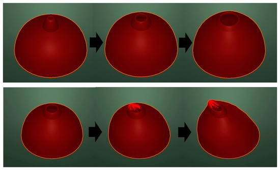
Figure 3.
Global deformation—dilation of the cervix (top). Local deformation—user manipulation (bottom).
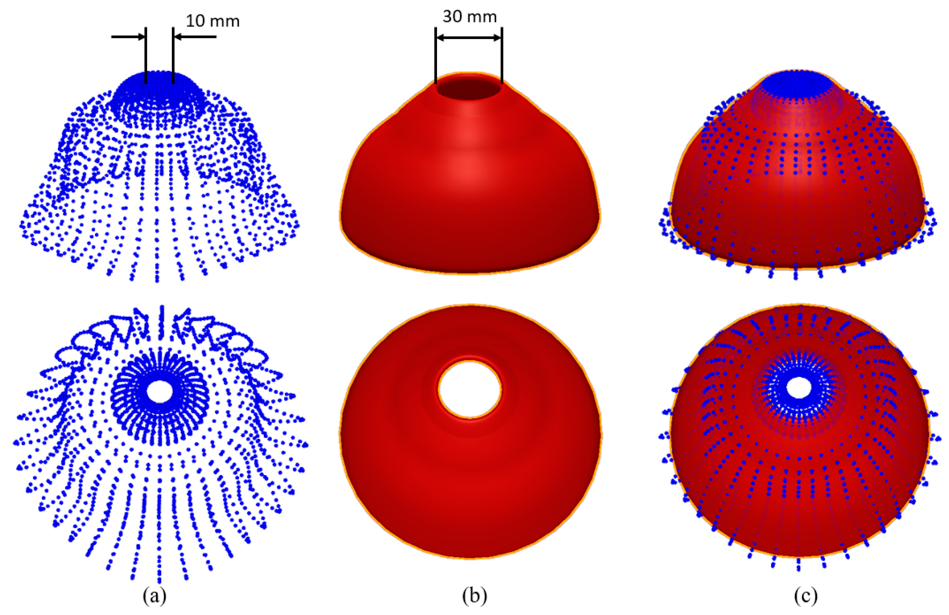
Local deformation can be updated on the HMD by transmitting the position of the control points computed from the deformed surface mesh. Global deformation, however, is difficult to represent by updating the relatively small number of control points because there are not enough degrees of freedom (DoF) to fully represent the deformation. Figure 4 shows the difference between the dilated cervix model and the model reconstructed from the control points, which are computed by an inverse mapping matrix in the vaginal examination training simulation. The red surface indicates the resulting deformed surface mesh in the server PC. Blue points indicate surface vertices reconstructed in the HMD using 32 control points computed from the deformed surface mesh and the inverse mapping matrix.
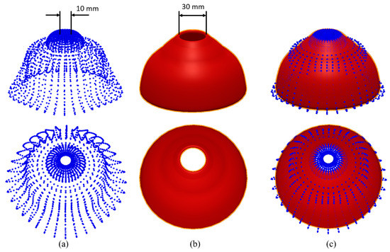
Figure 4.
The difference (c) between the reconstructed surface (a) and the original surface (b).
The root mean square error between two surfaces is 4.70 mm. The error is higher at the cervix entrance. The diameter of the cervix entrance (red) is 30 mm, but the diameter of the reconstructed cervix is 10 mm. One of the essential skills of the vaginal examination is assessing cervix dilation in cm by using two fingers. Incorrect visual feedback can confuse trainees as a result of the discrepancy between the visual and haptic feedback, which in turn may lead to motion sickness and negatively impact the training. This effect is due to the large deformation that cannot be fully reconstructed from the transmitted control points.
To address this issue, we create closed and dilated cervix models and define a simulation state as the diameter of the cervix. A cervix model is dilated by blending the predefined shapes during a simulation. For example, if the simulation state is 25 mm, then a weight value, 0.5 can be used to blend the closed and 50 mm diameter cervix model in equal proportions. i.e., half and half. Control points are placed to embed the predetermined global shapes, and a mapping from the control points to each shape is then computed prior to the simulation. The mapping matrix of a blended shape is computed by blending precomputed mapping matrices with a weighting value as shown in Equation (3).
The proposed method can also be applied to simulations with multiple predefined shapes. The mapping matrix of two target shapes, and , and the corresponding weight value can be determined by a simulation state. If the diameter of a cervix model is 25 mm, the closed and 50 mm diameter models are used as the target shapes, and 0.5 is used as a weight value. The update rate of visual feedback must be higher than 30 Hz [17]. Mapping matrices of predetermined shapes are computed and stored in the HMD to minimise computational load and data transmission during a simulation. The changes between two shapes can be divided into finite steps. The inverse matrix of each step can be computed by Equation (4) and stored in advance if computer memory allows. Otherwise, the inverse computation can also be computed during the simulation, as long as this does not affect real-time updates. For example, the deformation from rest to dilated cervix was divided into 50 steps, and 50 inverse matrices were precomputed and stored in the VE training simulation.
2.3. Framework Using MSFFD
The overall process involving local and global deformation transmission is shown in Figure 5. We use a server-client model that represents a PC (Server) where most computations are performed and the HMD (Client) that renders the virtual scene onto the real world. The surface mesh is deformed in the server by the physics model, together with user input. Control points are then updated from the updated surface mesh, together with the corresponding inverse mapping matrix. Indexes for the two target shapes and weight values are transmitted to the client for global deformation updates. Control points are transmitted to the client for local deformation updates. A mapping matrix of the blended shape is constructed in the client from prestored matrices. The surface mesh in the client is then updated from the received control points and a blended mapping matrix.
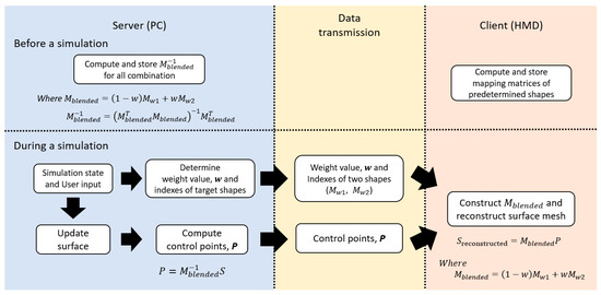
Figure 5.
The overall process of the proposed framework.
3. Results
3.1. Round-Trip Time and Processing Time
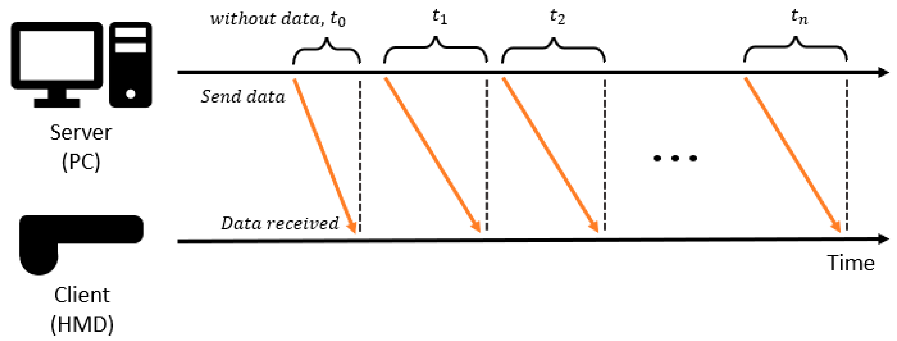
The proposed framework was verified in terms of the time taken to deliver the deformed mesh and the accuracy of the transmitted mesh in a vaginal examination training simulation. The analysis and verification were carried out using a server PC with Intel® Core™ i7-6700K CPU, NVIDIA GeForce GTX 1080, 5G Wi-Fi by NetGear, and a HoloLens 1st Generation. The Mixed Reality Toolkit (MRTK) was used to establish the network communication between the PC and the HMD. Latency occurs when data are transmitted to the HMD through the network, and the HMD processes these current data to receive the next data, as shown in Figure 6. Even if data transmission can be performed without latency, if the processing takes time, latency between visual feedback and user input can increase. We used the round-trip time (RTT) and processing time, , as shown in Figure 6 to analyse the tendency of latency against the number of vectors in a server-client model. RTT has been used as a metric to indirectly measure latency in the network [18]. It is defined as the time taken to send data from a server and receive a confirmation signal from the HMD. Three-dimensional vectors, such as surface vertices and normals required for visual feedback, are transmitted to the HMD.
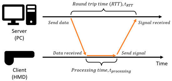
Figure 6.
The overall process of the proposed framework.
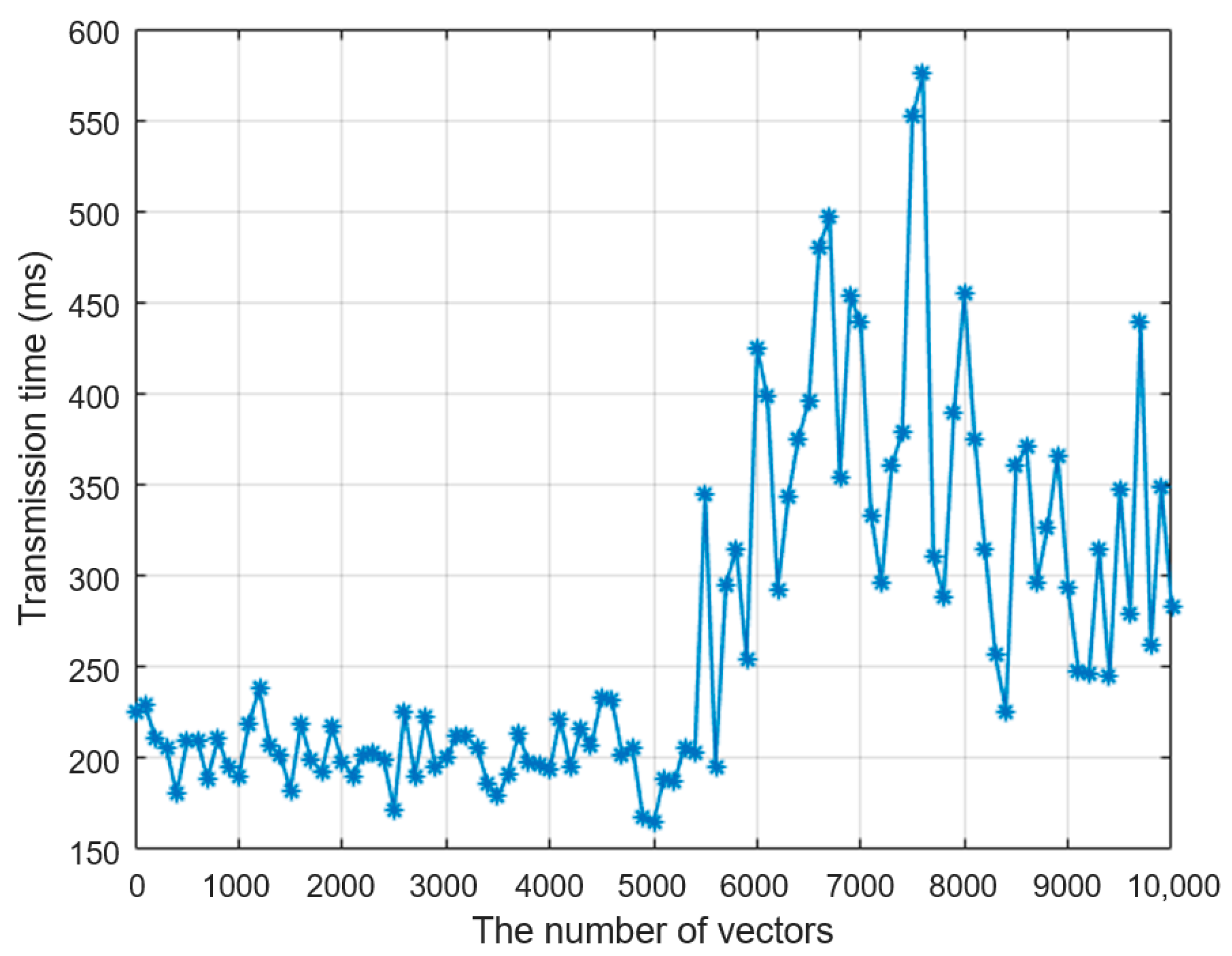
Figure 7 shows the average RTT when the data were sent five times as a function of the number of vectors transmitted. The number of vectors increases by 100 from 0 to 10,000. RTT is around 225 ms, even if the number of vectors is zero. This is because RTT includes the latency of the update loop at the server, and there is an inherent latency in the network communication established on Web Real-Time Communication (WebRTC) [19]. As the number of vectors increases, the latency fluctuates around 200 ms up to 5000 vectors, when the latency begins to increase consistently.

Figure 7.
Round-trip time (RTT) against the number of vectors.
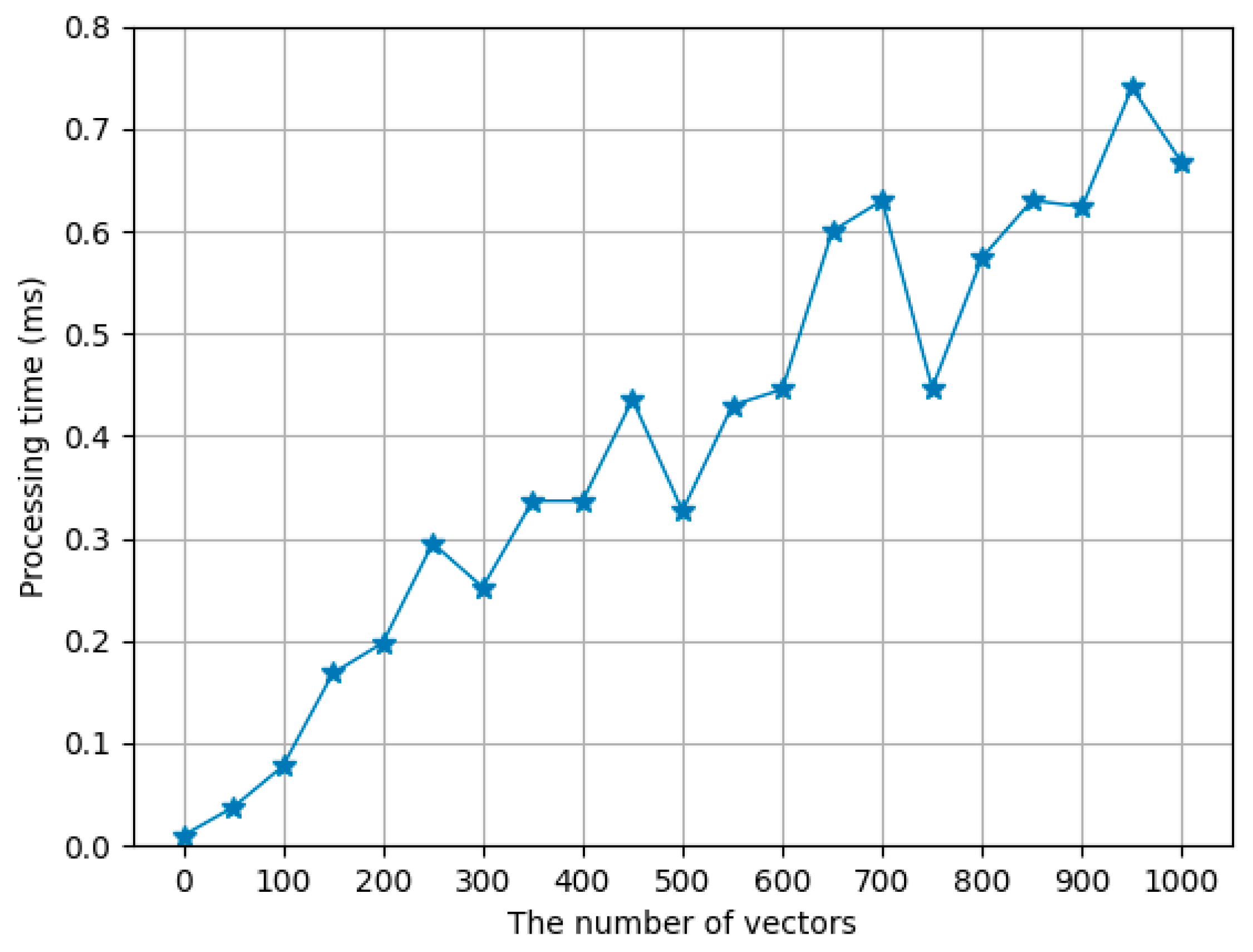
From Figure 7, we can conclude that the number of three-dimensional vectors must be smaller than 5000 to avoid additional latency in data transmission. This is in addition to the inevitable latency present in the communication network. RTT involves not only data transmission time but also processing time, which is analysed separately from RTT. The time difference between when the data are received in the HMD and when a confirmation signal is sent to the PC is measured as shown in Figure 6. The number of vectors increases by 50 from 0 to 1000, and the average processing time of 10 times data communication is computed for each number of vectors. Figure 8 shows how the processing time increases proportionally to the number of vectors. The processing time is less than 1 ms up to 1000 vectors, which means that data transmission is dominant in the latency. The processing time, however, must be small enough as a virtual scene needs to be rendered at a refresh rate of at least 30 Hz for smooth visual feedback. Accordingly, all the computations on the HMD, such as processing data to obtain control points, computing surface meshes from the control points, and rendering a scene, must be performed at at least a 30 Hz update rate.

Figure 8.
Processing time over the number of vectors.
A pair of surface vertex and normal is required to render a 3D object in the virtual world. The total number of vectors must be as small as possible to provide more computational margin in the HMD, where computational power is lower than the PC. The number of vertices in our cervix model and vulva model used in the simulation are 2160 and 2400, respectively. Therefore, a total of 9120 vectors would need to be transmitted in real time without latency to render the 3D scene on the HMD directly. Our framework can reduce this total number of vectors by only transmitting the control points of the cervix and vulva model.
3.2. Verification on Stanford Bunny Simulation
The proposed framework was verified in terms of latency caused by data transmission and the accuracy of transmitted surface meshes in the simulation. We have applied the proposed framework to a simulation involving interaction with a deformable Stanford Bunny model and the VE training simulation. Position-based dynamics [20] were used to compute the deformation of an object in both simulations. The latencies were compared in both cases when surface vertices and normals are sent and control points are sent instead of surface meshes. The accuracy was measured by root mean square (RMS) position error between the original mesh and a reconstructed mesh from received control points. Measuring end-to-end latency from user input to visual response in AR requires external sophisticated devices [21]. Instead of end-to-end latency, we recorded the time when data were sent to the HMD on the PC and the time when data were received on the HMD to measure latency caused by data transmission. We assumed that a constant communication lag between the PC and HMD was zero to analyse latency caused by data transmission separately from any inherent delay in the network. This means that if a signal is sent to the HMD without data, then the transmission time is assumed to be zero. The initial time difference, caused by unsynchronised clocks between the PC and HMD, and an inherent delay of the network was measured. Empty data were sent to the HMD 100 times. The time when the data were sent from the PC and the time when a signal was received at the HMD were measured on the PC and HMD, respectively as shown in Figure 9. The average difference was calculated and used as the initial time difference, . Time differences were measured for steps: and then the latency was calculated by subtracting the initial time difference from all measured times: .

Figure 9.
Measurement of latency caused by data transmission from the PC to the HMD.
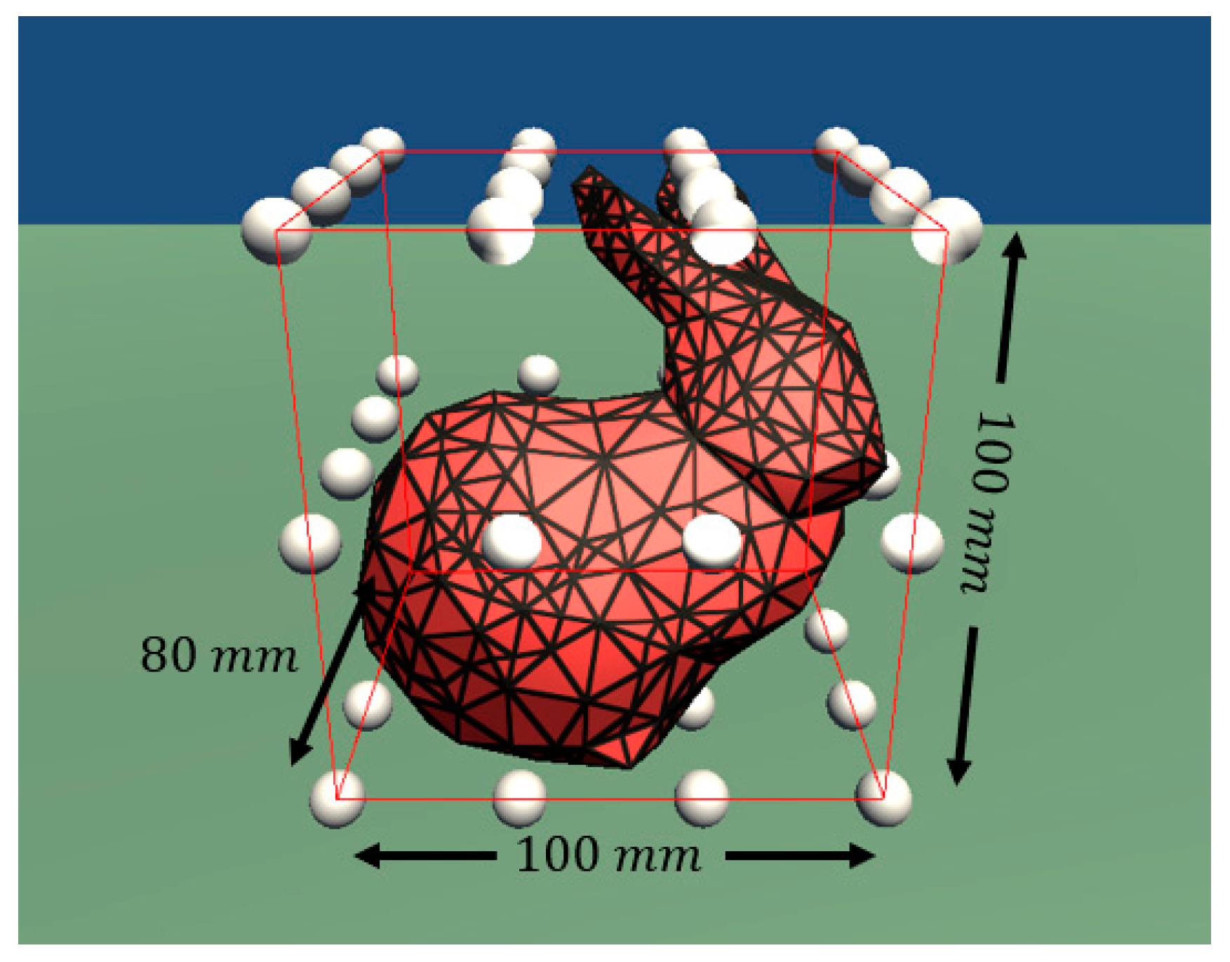
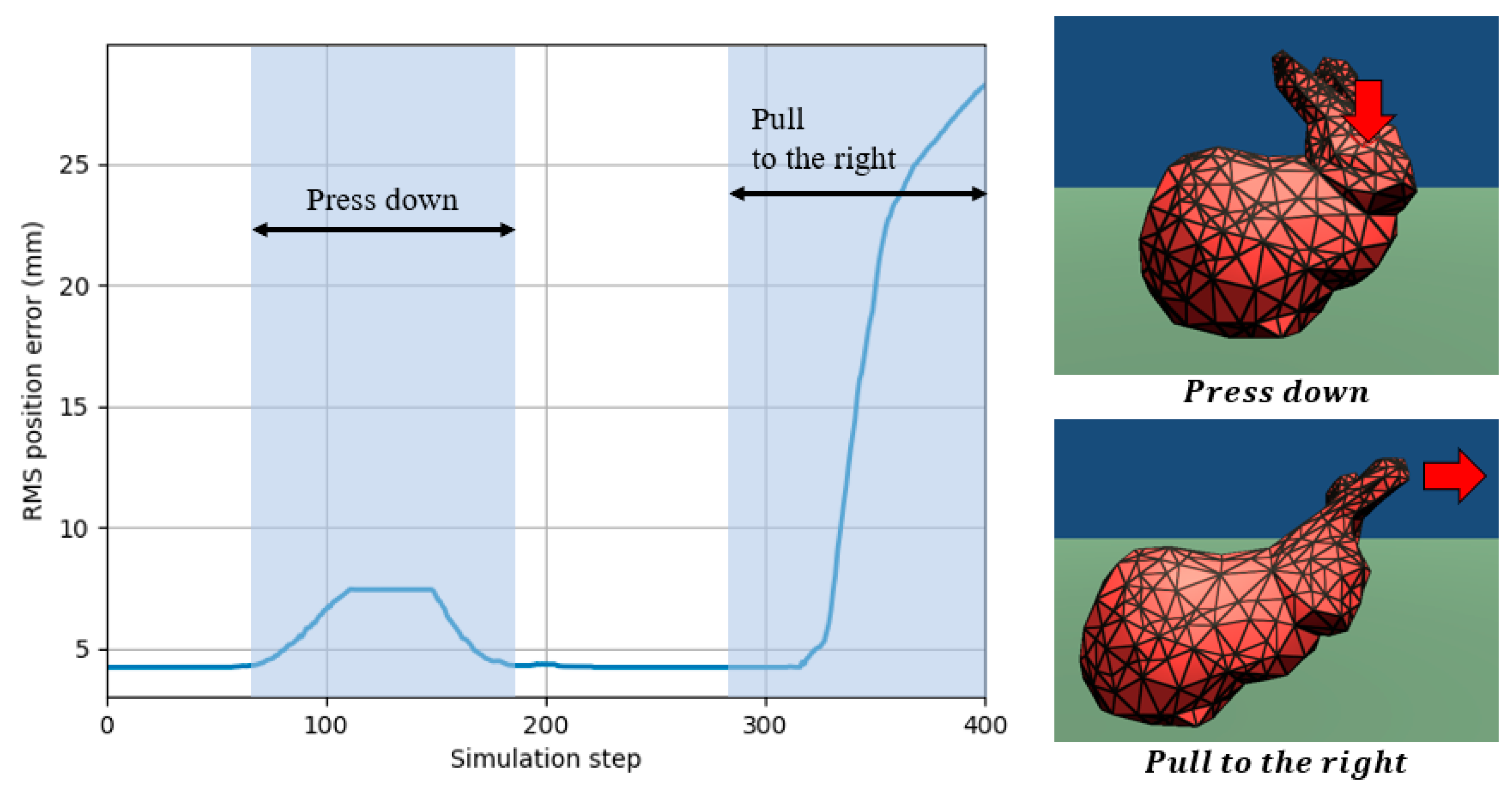
In the simulation of the Stanford Bunny model, we grabbed and moved some points of the model that comprised 524 vertices and 950 triangular surface meshes, as shown in Figure 10. A total of 48 control points (4 × 4 × 3) were placed to embed the model.
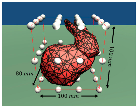
Figure 10.
Stanford Bunny model embedded in a lattice of control points (white).
In the proposed framework, 48 control points were transmitted to the HMD, and a surface mesh was reconstructed from the received control points. Global deformation was not transmitted in this simulation because no specific scenario was defined. A total of 524 pairs of vertices and normals are needed to directly render the Stanford Bunny model on the HMD without the proposed framework, which will result in 1048 vectors sent to the HMD for 400 steps. The average and maximum latency caused by sending 1048 vectors are 281 and 315 ms, respectively. In the case of the proposed framework, only 48 control points are needed to render a virtual scene. The average and maximum latency over 400 simulation time steps caused by sending 48 control points are 6 and 51 ms, respectively. The average and maximum latency are summarised in Table 1.

Table 1.
Average and maximum latency comparison and reduction rate in the Stanford Bunny simulation.
The accuracy of the proposed method was verified by the RMS position error between the original mesh in the server and the reconstructed mesh in the client. RMS error was measured for 400 simulation steps. Figure 11 shows the RMS error over time and the snapshots of the simulation. The initial RMS error of 4 mm was caused by an error in the inverse mapping matrix. The error was 4% compared to the longest length of the model, 100 mm. The error increased by up to 7.5 and 29 mm when the head was pressed down, and the ear was pulled to the right, respectively. The relative errors compared to the longest length are 7.5% and 29%, respectively. The error increases as the shape of the model changes from the initial shape. This is because the global deformation was not transmitted as target shapes were not predetermined in this simulation.
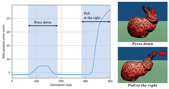
Figure 11.
Root mean square position error of the Stanford Bunny model over simulation time steps.
3.3. Verification on Vaginal Examination Simulation
We have also applied the proposed framework to our VE training simulation, as shown in Figure 1, and measured the latency and accuracy. The cervix model and vulva model are composed of 2160 and 2400 vertices, respectively, with a total of 32 (4 × 4 × 2) and 72 (6 × 6 × 2) control points (Figure 1). In the simulation, as the training progresses, the position and orientation of the baby’s head, as well as the cervix model, change and result in the entrance of the cervix model being dilated. Therefore, simulation states are defined as the cervix diameter, position of the cervix and baby’s head, and orientation of the baby’s head. However, to simplify the latency and accuracy measurements, we used only the cervix diameter as a simulation state. Two shapes were predefined to simulate the dilation of the cervix model: At Rest and Dilated. The global deformation was computed by blending the two shapes. The deformation from At Rest to Dilated was divided into 50 steps. The inverse matrices of 50 blended matrices were precomputed and stored in the server beforehand to reduce the computational burden during a simulation. Mapping matrices of the At Rest and Dilated shapes were stored in the client, and a blended matrix was computed based on Equation (3) when a weighting value was received. The diameter of the cervix was determined from the simulation state. Control points were computed by the corresponding precomputed inverse matrix and then transmitted to the client, together with the corresponding weighting value. A total of 4560 pairs of vertices and normals were needed to directly render a virtual scene on the client. A total of 9120 vectors were sent to the client for 500 steps. The average and maximum latency caused by sending 9120 vectors were 18,969 and 40,092 ms, respectively. In the case of the proposed framework, 104 control points were needed to render the virtual scene. The average and maximum latency over 500 simulation time steps caused by sending 104 control points were 7 and 34 ms, respectively. The average and maximum latency are summarised in Table 2.
Table 2.
Average and maximum latency comparison and reduction rate in the VE training simulation.
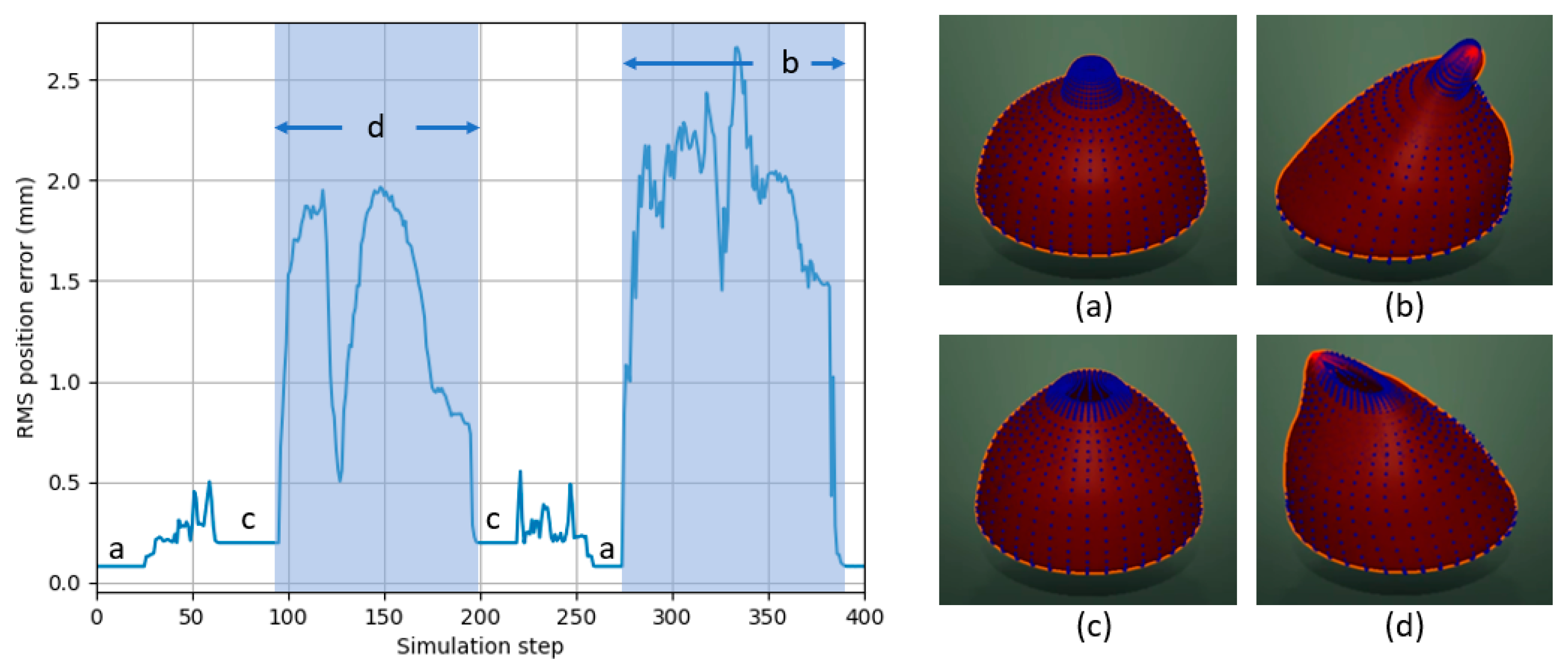
The cervix model with large deformation was used for the accuracy analysis. Figure 12 shows the RMS position error as a function of the simulation time steps. The error increases by up to about 0.5 mm when the cervix model dilates and contracts. The error increases by up to 2 and 2.8 mm when the user grabs and manipulates some points of the dilated and initial cervix model, respectively. The error is proportional to the amount of manipulation by the user. However, the error is relatively small when the cervix model dilates and contracts since the global deformation is transferred by a blended mapping matrix. The diameter of the cervix model is 100 mm; therefore, the maximum relative error is less than 3%.

Figure 12.
Root mean square position error of the cervix model over simulation time steps: (a) the cervix model is closed; (b) a user is pulling the cervix model to the right; (c) the cervix model is dilated; (d) a user is pulling the dilated cervix model to the left.
4. Discussion
The proposed framework has been verified on both an interactive simulation of the Stanford Bunny model and a training simulation of vaginal examination during labour. The number of vectors required to render a virtual scene was reduced from 1048 to 48 in the Stanford Bunny simulation and from 9160 to 104 in the VE training simulation. The number of control points is higher in the VE training simulation, but the maximum latency is higher in the Stanford Bunny simulation. This is because the latency varies depending on the network state. In the Stanford Bunny and VE training simulation, the average latency is reduced to 6 and 7 ms, respectively, which is less than 15 ms, the maximum allowable latency to avoid motion sickness in VR simulation [22]. In AR simulations, the user can still see the real environment through the HMD, unlike in VR simulations. Therefore, the latency only causes a visual discrepancy between real-world and overlaid virtual content. For this reason, the latency condition for avoiding motion sickness can be further alleviated in AR simulations. The maximum relative error was 29% and 2.8% in the Stanford Bunny and VE simulation, respectively. In the Stanford Bunny simulation, the model was deformed by a user interaction without a predefined scenario; therefore, the error increases proportionally to the magnitude of deformation. If the global deformation cannot be predefined and the deformation induced by the interaction is large, the error could increase in the proposed framework. In the VE training simulation, however, the relative error was less than 3% because deformed shapes were predefined as part of the training scenario, using the closed and dilated cervix shapes as the target shapes, and the global deformation was transmitted by a weighted value. The number of control points can be further reduced whilst maintaining or improving the accuracy of the transmitted mesh by using advanced free-form deformation techniques [23,24] in the proposed framework.
5. Conclusions
This paper proposes a framework that can achieve real-time rendering of the 3D scene aligned to the real world on an off-the-shelf AR HMD by reducing the amount of data transmitted whilst retaining all the necessary information for accurate and high-resolution 3D rendering. We have categorised deformation in a medical training simulation into local deformation by user interaction and global deformation as a result of the simulation scenario. Local and global deformation is transmitted in a different way to reduce the position error between a transmitted mesh and the original mesh. Control points embedding a target mesh are transmitted, and a surface mesh is constructed from the received control points for local interaction. Our framework can be applied to other medical simulations since the deformation of an organ model is often the result of both user interaction and the specific training scenario, as is the case for the VE simulation, or the deformation range can be restricted. The proposed framework can achieve efficient and accurate mesh transmission in the case of large deformations of the complete shape as a result of a given scenario, but it can also be used without global transmission in simulations with small deformation. This enables direct and seamless rendering of a virtual scene onto the real world on an HMD without the need for additional external real-time tracking, which is an important step in the further development and adoption of AR-based medical simulators.
Author Contributions
Methodology, M.K.; Software, M.K.; Supervision, F.B.; Validation, M.K.; Writing—original draft, M.K.; Writing—review & editing, F.B.; All authors have read and agreed to the published version of the manuscript.
Funding
This research was funded by the Imperial Health Charity grant number 161715a and The APC was funded by Imperial Open Access Fund.
Conflicts of Interest
The authors declare no conflict of interest.
References
- Kwon, H.-B.; Park, Y.-S.; Han, J.-S. Augmented Reality in Dentistry: A Current Perspective. Acta Odontol. Scand. 2018, 76, 497–503. [Google Scholar] [CrossRef] [PubMed]
- Kim, Y.; Kim, H.; Kim, Y.O. Virtual Reality and Augmented Reality in Plastic Surgery: A Review. Arch. Plast. Surg. 2017, 44, 179–187. [Google Scholar] [CrossRef] [PubMed] [Green Version]
- Ayoub, A.; Pulijala, Y. The Application of Virtual Reality and Augmented Reality in Oral & Maxillofacial Surgery. BMC Oral Health 2019, 19, 238. [Google Scholar] [CrossRef] [Green Version]
- Chang, C.; Bang, K.; Wetzstein, G.; Lee, B.; Gao, L. Toward the Next-Generation VR/AR Optics: A Review of Holographic near-Eye Displays from a Human-Centric Perspective. Optica 2020, 7, 1563–1578. [Google Scholar] [CrossRef] [PubMed]
- Greenberg, P.B.; Tang, K.S.; Cheng, D.L.; Mi, E. Augmented Reality in Medical Education: A Systematic Review. Can. Med. Educ. J. 2020, 11, 81–96. [Google Scholar] [CrossRef]
- Barbieri, L.; Bruno, F.; Cosco, F.; Muzzupappa, M. Effects of Device Obtrusion and Tool-Hand Misalignment on User Performance and Stiffness Perception in Visuo-Haptic Mixed Reality. Int. J. Hum. Comput. Stud. 2014, 72, 846–859. [Google Scholar] [CrossRef]
- Nabiyouni, M.; Scerbo, S.; Bowman, D.A.; Höllerer, T. Relative Effects of Real-World and Virtual-World Latency on an Augmented Reality Training Task: An AR Simulation Experiment. Front. ICT 2016, 3, 34. [Google Scholar] [CrossRef] [Green Version]
- Gaffary, Y.; Le Gouis, B.; Marchal, M.; Argelaguet, F.; Arnaldi, B.; Lecuyer, A. AR Feels “Softer” than VR: Haptic Perception of Stiffness in Augmented versus Virtual Reality. IEEE Trans. Vis. Comput. Graph. 2017, 23, 2372–2377. [Google Scholar] [CrossRef] [PubMed] [Green Version]
- Klein, G.; Murray, D. Parallel Tracking and Mapping for Small AR Workspaces. In Proceedings of the 2007 6th IEEE and ACM International Symposium on Mixed and Augmented Reality (ISMAR), Nara, Japan, 13–16 November 2007; pp. 225–234. [Google Scholar] [CrossRef]
- Ababsa, F.E.; Mallem, M. Robust Camera Pose Estimation Using 2D Fiducials Tracking for Real-Time Augmented Reality Systems. In Proceedings of the 2004 ACM SIGGRAPH International Conference on Virtual Reality Continuum and Its Applications in Industry, Singapore, 16–18 June 2004; pp. 431–435. [Google Scholar] [CrossRef] [Green Version]
- Koulieris, G.A.; Akşit, K.; Stengel, M.; Mantiuk, R.K.; Mania, K.; Richardt, C. Near-Eye Display and Tracking Technologies for Virtual and Augmented Reality. Comput. Graph. Forum 2019, 38, 493–519. [Google Scholar] [CrossRef]
- Lu, S.; Perdomo, Y.P.S.; Jiang, X.; Zheng, B. Integrating Eye-Tracking to Augmented Reality System for Surgical Training. J. Med. Syst. 2020, 44, 192. [Google Scholar] [CrossRef] [PubMed]
- Arias, T.; Tran, A.; Breaud, J.; Fournier, J.P.; Bongain, A.; Delotte, J. A Prospective Study into the Benefits of Simulation Training in Teaching Obstetric Vaginal Examination. Int. J. Gynecol. Obstet. 2016, 133, 380–384. [Google Scholar] [CrossRef] [PubMed]
- Shea, K.L.; Rovera, E.J. Vaginal Examination Simulation Using Citrus Fruit to Simulate Cervical Dilation and Effacement. Cureus 2015, 7, e314. [Google Scholar] [CrossRef] [PubMed] [Green Version]
- Sederberg, T.W.; Parry, S.R. Free-Form Deformation of Solid Geometric Models. In SIGGRAPH ’86: Proceedings of the 13th Annual Conference on Computer Graphics and Interactive Techniques; Association for Computing Machinery: New York, NY, USA, 1986; Volume 20, pp. 151–160. [Google Scholar] [CrossRef]
- Coquillart, S. Extended Free-Form Deformation: A Sculpturing Tool for 3D Geometric Modeling. In SIGGRAPH ’90: Proceedings of the 17th Annual Conference on Computer Graphics and Interactive Techniques; Association for Computing Machinery: New York, NY, USA, 1990; Volume 24, pp. 187–196. [Google Scholar] [CrossRef] [Green Version]
- Peterlik, I.; Nouicer, M.; Duriez, C.; Cotin, S.; Kheddar, A. Constraint-Based Haptic Rendering of Multirate Compliant Mechanisms. IEEE Trans. Haptics 2011, 4, 175–187. [Google Scholar] [CrossRef] [PubMed]
- Maskey, N.; Horsmanheimo, S.; Tuomimäki, L. Analysis of Latency for Cellular Networks for Smart Grid in Suburban Area. In Proceedings of the 2014 5th IEEE PES Innovative Smart Grid Technologies Europe (ISGT Europe), Istanbul, Turkey, 12–15 October 2014; pp. 1–4. [Google Scholar] [CrossRef]
- García, B.; Gortázar, F.; López-fernández, L.; Gallego, M.; París, M. WebRTC Testing: Challenges and Practical Solutions. IEEE Commun. Stand. Mag. 2017, 1, 36–42. [Google Scholar] [CrossRef]
- Müller, M.; Heidelberger, B.; Hennix, M.; Ratcliff, J. Position Based Dynamics. J. Vis. Commun. Image Represent. 2007, 18, 109–118. [Google Scholar] [CrossRef] [Green Version]
- di Luca, M. New Method to Measure End-to-End Delay of Virtual Reality. Presence Teleoperators Virtual Environ. 2010, 19, 569–584. [Google Scholar] [CrossRef]
- Elbamby, M.S.; Perfecto, C.; Bennis, M.; Doppler, K. Toward Low-Latency and Ultra-Reliable Virtual Reality. IEEE Netw. 2018, 32, 78–84. [Google Scholar] [CrossRef] [Green Version]
- Ono, Y.; Chen, B.Y.; Nishita, T.; Feng, J. Free-Form Deformation with Automatically Generated Multiresolution Lattices. In Proceedings of the 2002 1st International Symposium on Cyber Worlds, Tokyo, Japan, 6–8 November 2002; pp. 472–479. [Google Scholar] [CrossRef]
- Feng, J.; Shao, J.; Jin, X.; Peng, Q.; Forrest, A.R. Multiresolution Free-Form Deformation with Subdivision Surface of Arbitrary Topology. Vis. Comput. 2006, 22, 28–42. [Google Scholar] [CrossRef]


Publisher’s Note: MDPI stays neutral with regard to jurisdictional claims in published maps and institutional affiliations. |
© 2021 by the authors. Licensee MDPI, Basel, Switzerland. This article is an open access article distributed under the terms and conditions of the Creative Commons Attribution (CC BY) license (https://creativecommons.org/licenses/by/4.0/).