Featured Application
The resource-constrained two-way wiretap channel mobile relay system provides a promising security solution for cooperative sensor networks in which low-cost sensors need to exchange data to jointly complete tasks such as localization and anomaly detection.
Abstract
Relay communication is emerging as a promising solution to improving the reliability of long-distance communication systems. However, transmitting data in a secure way is challenging due to the possibility of eavesdroppers wiretapping such systems. To address the challenge, this paper proposes a joint secure transmission and graph mobility model. With the proposed model, the secrecy rate of the resource-constrained two-way wiretap channel mobile relay system is formulated as a mixed integer nonlinear programming (MINLP) problem. Furthermore, efficient algorithms that achieve a local optimal solution are derived. Numerical results are provided to validate the performance of the proposed algorithms.
1. Introduction
It is well known that secure information transmission is an essential communication requirement. Resource-constrained two-way communication occurs in a four-node network, where two users exchange information through a relay station under the condition of an eavesdropper wiretapping the channels. This four-node relay-eavesdropper network has been widely studied [1,2,3,4,5], and with the help of relay, the network is able to adjust its uplink and downlink channels and thus improves the system security. With the rapid development of Internet of Things (IoT), huge numbers of long-distance sensors need to interact with each other to jointly complete tasks [6]. Resources such as time and energy in this type of cooperative sensor network are important factors that need to be carefully considered. Therefore, the resource-constrained relay-eavesdropper network is becoming a novel interesting research topic and is attracting considerable attention.
Currently, most existing works focus on two-way communication systems with fixed relays [7,8,9,10]. In particular, relay cooperative jamming has been studied extensively [7,8,9,10] to protect confidential message from wiretapping. This type of method, although effectively improving the secrecy rate, may lead to harmful interference and additional energy consumption [7,8]. Thus, to eliminate interference, interference cancellation techniques have to be taken into account [10]. On the other hand, in order to improve energy utilization efficiency, energy harvesting [7] or wireless energy transfer [8] is adopted to provide the relay and users with sufficient energy. Nowadays, there is a growing interest in deploying unmanned aerial vehicles (UAVs) in two-way relay systems [11,12,13]. UAV schemes indeed provide flexible mobile relays to implement air-to-ground or air-to-air wireless communication. However, for ground secure transmission, especially indoor, complicated pitches (e.g., warehouses), this beyond the reach of UAV-based relay system. Moreover, when an UAV serves as a flying relay, it requires large propulsion energy to keep itself aloft, which leads to a short life flight. This feature prevents the UAV from participating in many applications. Therefore, two-way secure relay system needs further investigation, and this paper presents an investigation of the secrecy rate region of a ground mobile vehicle-based relay system, which remains an open problem.
To quantify the performance gain brought by our scheme, this paper proposes a two-way secure transmission and a graph mobility model, as well as formulating a secrecy rate maximization optimization problem with resource allocations incorporating path planning constraints, which represents a mixed integer nonlinear programming (MINLP) problem. The major challenges in solving this discrete problem are twofold. First, the path planning refers to a considerable number of discrete binary variables, and the solution space grows exponentially with the number of anchor points. This characteristic results in a substantial difference from the design of UAVs’ trajectories, which only involve continues variables. Second, when the relay moves along an unknown path, finding the achievable secrecy rate becomes very challenging. This is because two major reasons. One is that the transmission time at different location point needs to be determined. The other is that the powers at relay and users at each location need to be jointly optimized. As a result, in contrast to the fixed relay case, the dimension of variables significantly increase, resulting in additional nonlinear coupling between time allocation and uplink–downlink power allocation. In order to overcome the above challenges, auxiliary and relaxation methods are adopted to transform the non-convex problem into a convex problem, and a local optimal solution is derived. Finally, numerical results show that our mobile relay scheme outperforms the fixed relay scheme, and the relay trajectory is highly dependent on noise power.
Notation: Italic letters, simple bold letters, and capital bold letters represent scalars, vectors, and matrices, respectively. denote the transpose, inverse and, vectorization operators of a matrix, respectively. takes the expectation of a random variable, and is the modulus of the complex-valued number. The notation is used as max(a,0); symbol represents the identity matrix. Curlicue letters denote sets; represents a sequence; and is a column vector.
2. Materials and Methods
2.1. System Model
2.1.1. Mobility Model
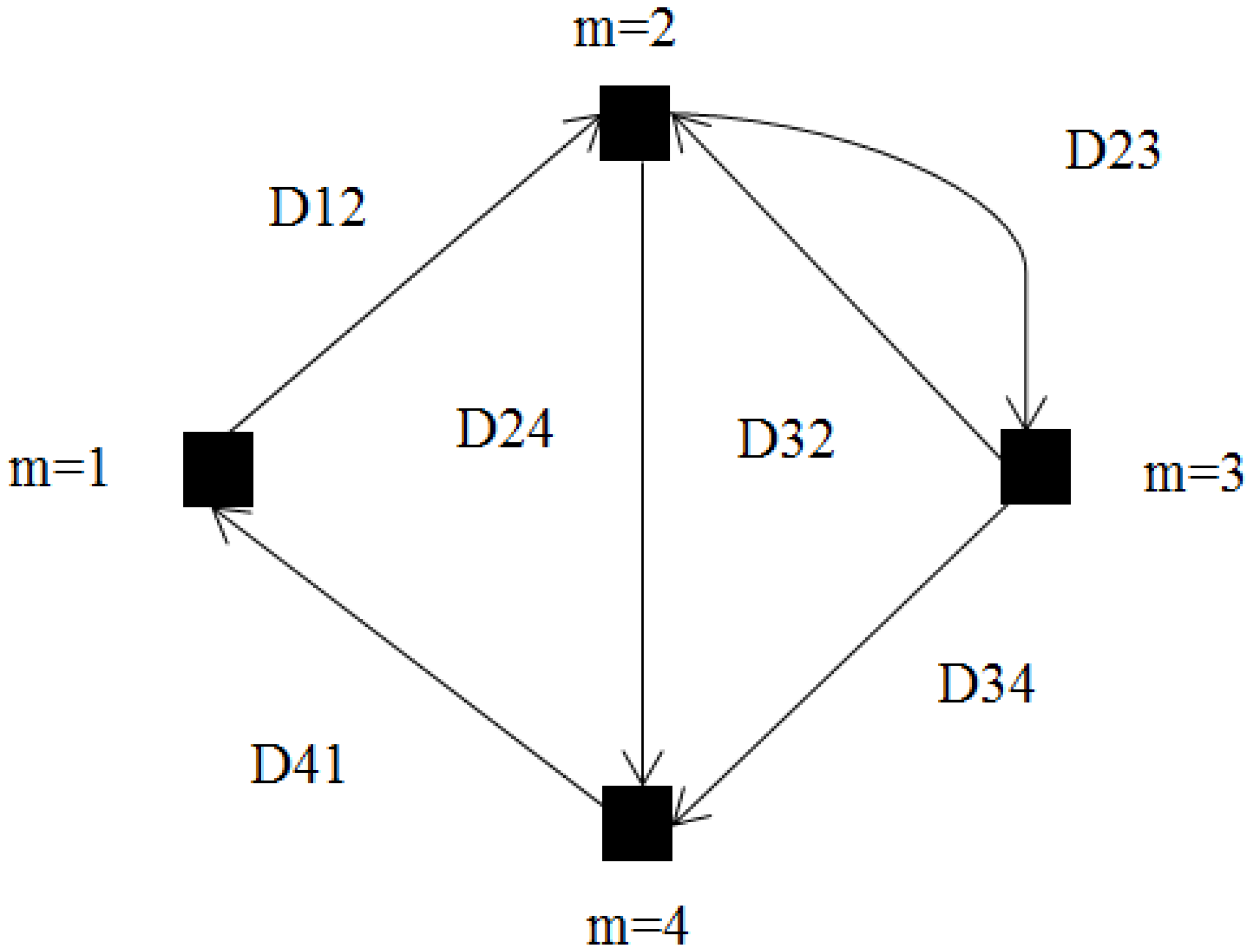
The two-way wireless secure transmission mobile relay system shown in Figure 1 was considered, and it consists of two IoT users (Alice and Bob), an eavesdropper (Eve), and a relay. The relay is equipped with N antennas and mounted on a ground mobile vehicle. Alice, Bob, and Eve are configured with a single antenna. Alice and Bob exchange data through the mobile relay under the condition of Eve eavesdropping the whole process. The scenario is described as a directed graph as shown in Figure 2, where is the set of M vertices representing the possible stopping points, and is the set of directed edges representing the allowed movement paths [14,15]. We let , be an asymmetric non-negative real distance matrix associated with , and we assume that the following three conditions hold:
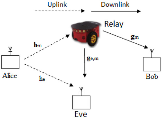
Figure 1.
System model.
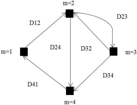
Figure 2.
Mobility model.
- (1)
- The mobile relay returns to the starting point.
- (2)
- The mobile relay visits all important positions.
- (3)
- There is no subtour in the planned path.
Accordingly, we define a selection path variable , where if the vertex m, , appears in the visiting path and otherwise. In addition, we introduce an matrix with variables being set to 1 or 0, and interpret the value 1 (0 resp.) to mean “in path” (“not in path” resp). Then, motion distance is given by
and we define set as the visiting path, which can be expressed as [14]:
Constraint (2a) guarantees that vertex m being visited only once at the most, while (2b) and (2c) are sub-tour elimination constraints, which ensure that the visiting path is connected. (2d) represents whether edge belongs to the path and also ensures that no self-loop appears in the visiting path. (2e) stands for the first vertex is the starting point. Note thatrepresents slack variables to guarantee a connected trajectory, and J is a constant set to .
With the moving time from vertex m to vertex j being , where a is the average velocity, the total moving time along a selected visiting path is
Furthermore, the total motion energy , along with the visiting path, is proportional to the total moving time [16]; it can be expressed as
where is a simple parameter function of velocity a of the model. It can be described as , where are parameters related to the weight of ground mobile vehicle (e.g., for the considered Pioneer 3DX robot, we have and ) [6,16,17].
2.1.2. Uplink Signal Model
For uplink transmission, Alice transmits vector to relay with transmit power , where is the number of symbols and is the transmission time assigned to the mobile relay at the stopping point m. Then, the received signal at relay is given by , where denotes the uplink channel vector of Alice-to-relay, and is the Gaussian noise with . Given perfect channel state information (CSI) at the receiver, and applying a receive beamformer (with ) to , the uplink signal-to-noise ratio (SNR) of Alice-to-relay at the relay is . On the other hand, as the computational capability of the eavesdropper is not known, we focus on the worst case scenario for facilitating secrecy supply. In particular, we assume that the eavesdropper is equipped with a noise-free receiver and able to remove other interference. In this case, the received signal at Eve is given by , where denotes the uplink wiretap channel scalar of Alice-to-Eve, and is the Gaussian noise with . Applying a receive beamformer (with to , the uplink wiretap SNR of Alice-to-Eve at Eve is . Therefore, the uplink achievable secrecy rate at the mth stopping point from Alice to relay is given by
2.1.3. Downlink Signal Model
For downlink transmission, the relay uses to generate a symbol with power . Then, the relay transmits to Bob with the transmit beamforming vector , which is given by , . Therefore, the received signal at Bob is , where is the downlink channel vector of relay-to-Bob, and is the Gaussian noise at Bob with . The received signal at Eve is given by , where denotes the downlink wiretap channel vector of relay-to-Eve, and is the Gaussian noise with . Applying a receive beamformer with to , the downlink wiretap SNR of relay-to-Eve at Eve is . Therefore, the downlink achievable secrecy rate at the stopping point from relay to Bob is given by
2.2. Achievable Secrecy Rate Problem Formulation
The achievable secrecy rate region of the resource-constrained two-way mobile relay system is the average of all combinations of the worst case uplink–downlink achievable secrecy rate; therefore, the achievable secrecy rate requirement that the system needs to meet is
where T is the time duration, consisting of all transmission time and total moving time. Moreover, the transmit power and energy requirements must also satisfy
where and Q are transmit power and initial available energy at Alice, respectively. In addition, , E, and are the transmit power, initial available energy, and motion energy of the relay, respectively. If the relay is fixed, ; otherwise, , which is determined by a selected visiting path. Having the power allocation and graph mobility constraints satisfied, the achievable secrecy rate problem is formulated as P1.
where the constraints mean:
(2) (10c) ensures that the mobile ground vehicle moving and data transmission are completed in T seconds.
(3) (10g) is the constraint that the stopping time and power allocation are zeros provided that the vertex is not visited.
However, problem P1 is a MINLP problem due to the discontinuity of integer constraints of (10d), which is NP hard and nontrivial to solve [18]. Moreover, the secrecy rate depends on the transmit power and transmission time , which present unknown and nonlinear coupling with each other.
2.3. Local Optimal Solution to P1
To solve P1, we first utilize auxiliary and relaxation methods to transform the non-convex constraints of (10a) and (10b) into convex. Then, by fixing , an optimization problem P2 is derived, which is equivalent to P1. Through further transformation, P1 is converted to P3, which only involves variable . Lastly, we exploit the neighborhood search method (NSM) [19,20,21] and develop an iterative algorithm to obtain the local optimal solution.
2.3.1. Convex Approximation via Taylor Expansion
We first consider the constraints of (10a) and (10b) because of the nonlinear coupling between and , and . We replace with a new variable such that . Similarly, is replaced with a new variable satisfying . Therefore, the above constraints of (10a), (10b), and (10e)–(10g) of P1 are equal to the following:
Due to the non-convexity of the above Equations (11) and (12) [22], we need some transformations. For simplicity, we define four functions as follows:
According to [22], we can obtain the following theorem and properties.
Theorem 1.
Perspective function has convexity.
Property 1.
, , , and are concave with respect to and , respectively.
Proof of Property 1.
Since is the perspective transformation of , where represents any numerator of (16)–(19), according to Theorem 1, has the same convexity as [22], which is a concave function. Therefore, , and are concave with respect to and .
□
Property 2.
and are monotonically increasing functions of for all m.
Proof of Property 2.
Follows a similar proof to [14] (Property 1). □
2.3.2. Optimal Solution of (Namely ) and
Given , where is any feasible solution to P1, the constraint (2e) of can be discarded since it only involves . Combined with Equation (1) and (10c), it is proved in Appendix A that we can obtain the following equation:
Based on (13)–(15), (20)–(23), it is proved in Appendix B that P1 is equivalently transformed into the two-layer optimization problem shown below:
In P2, the right hand of (24c) is the crucial issue of the traveling salesman problem as shown below:
Problem (25) can be optimally solved via the software Mosek [23,24]. are supposed to be the optimal solution to the problem (25), and the optimal objective value of problem (25) is given by . Then, the (24c) constraint of P2 can be re-written as . Since other constraints of P2 are convex, P2 can be optimally solved by CVX. Denoting its solution as , the optimal with fixed can be obtained from and .
2.3.3. Local Optimal Solution of s
With , , , which were derived in a previous section, the secrecy rate, the left-hand sides of Equations (13) and (14) with , can be written as
Therefore, problem P1 is re-written as
To solve P3, an effective way is to apply the neighborhood search method (NSM) [19,20,21], which greatly reduces the amount of computation compared to an exhaustive search. The critical point of NSM is the idea of the neighborhood . Taking , for example, the neighborhood is
where is the size of neighborhood [21], and for arbitrary , the neighborhood is obtained in Algorithm 1.
| Algorithm 1 Computing the neighborhood |
|
2.3.4. Summary of Algorithm
At the beginning, we start from a feasible solution of and compute by solving P2 with . Then, we randomly select a candidate solution and compute . Next, we compare with . If , we update with and view as a new feasible solution to construct the next neighborhood. Otherwise, we check the to determine whether there are points not yet being sampled. If yes, we find another point within the neighborhood and proceed to the above steps; otherwise, we terminate the procedure.
To obtain the local optimal solution of , we repeat the above process and obtain a sequence of . The convergence point is guaranteed to be a local optimal solution to P1 [14]. To summarize the process given above, an algorithm for obtaining the local optimal solution to P3 (equal to P1) is proposed as Algorithm 2.
In terms of computational complexity, the computing problem (25) requires in the worst case [14,25]. Solving P2 by CVX requires a complexity of [14,26] due to the fact that P2 has variables. Therefore, the complexity order of Algorithm 2 is dominated by , where X is the number of iterations.
| Algorithm 2 Proposed local optimal solution to P1 |
|
3. Results
Numerical results are provided in this section to evaluate the performance of the resource-constrained two-way relay network. In particular, the distance-dependent path-loss model is adopted, where is the distance from user 1 (Alice: user 1; Bob: user 2) to the mth stopping point of the relay; is the path loss at distance m; and is the path-loss exponent set to be 2.5 [6,27]. Based on the path-loss model, channels and are generated according to . Similarly, the wiretap channels , and are generated according to and respectively, where and are the distance-dependent path loss of uplink and downlink wiretap channels, respectively. The receiver noise powers are set to dBm and dBm. Furthermore, within the duration of s, the energies available at Alice and relay are mJ and J, respectively. Each point in the figures is obtained by averaging over 100 simulation runs.
Based on the above settings, we simulate the secrecy rate map in a 20 m × 20 m = 400 m square area [14,27], which is a typical size of a smart warehouse. Inside this map, 2 IoT users, 1 eavesdropper, 1 relay with 8 () antennas, and vertices representing stopping points are randomly scattered, with the eavesdropper being near to the starting point of the relay.
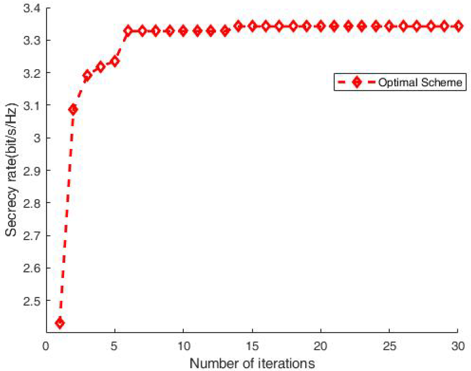
To verify the convergence of Algorithm 2 in the previous section, Figure 3 shows the relationship between the secrecy rate and the number of iterations. It can be seen that with , a stable result is obtained. This verifies the convergence of our proposed algorithm with a moderate number of iterations.

Figure 3.
Secrecy rate vs. iterations.
In order to illustrate the proposed scheme’s performance gains, Figure 4 shows a comparison between the fixed relay case and mobile relay scheme. The secrecy rate under the mobile relay scheme is much higher than that of the fixed case, which is almost zero due to the relay being near to Eve. Moreover, the performance gap concisely quantifies the secrecy rate gain brought by mobile relay, which demonstrates the advantage of employing movement of the relay.
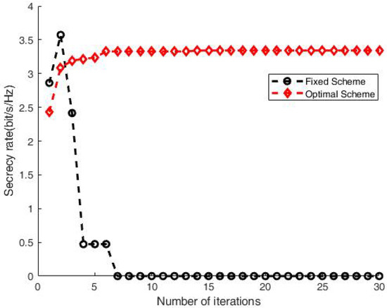
Figure 4.
Secrecy rate comparison between fixed relay case and moving relay scheme.
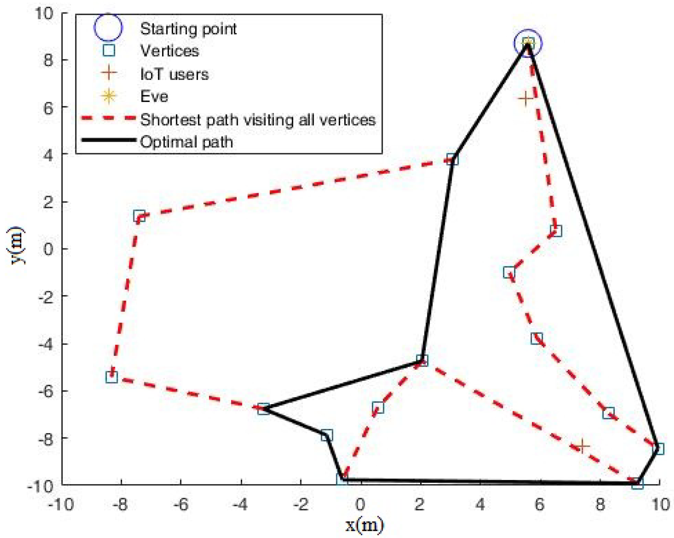
To gain more insight into the mobile relay scheme, Figure 5 can be observed, from which it can be observed that Algorithm 2 can automatically determine where to move and how far to move. The relay can smartly avoid the dangerous zones that are close to the eavesdropper.
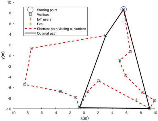
Figure 5.
Path for mobile relay with M = 15 when noise power dBm.
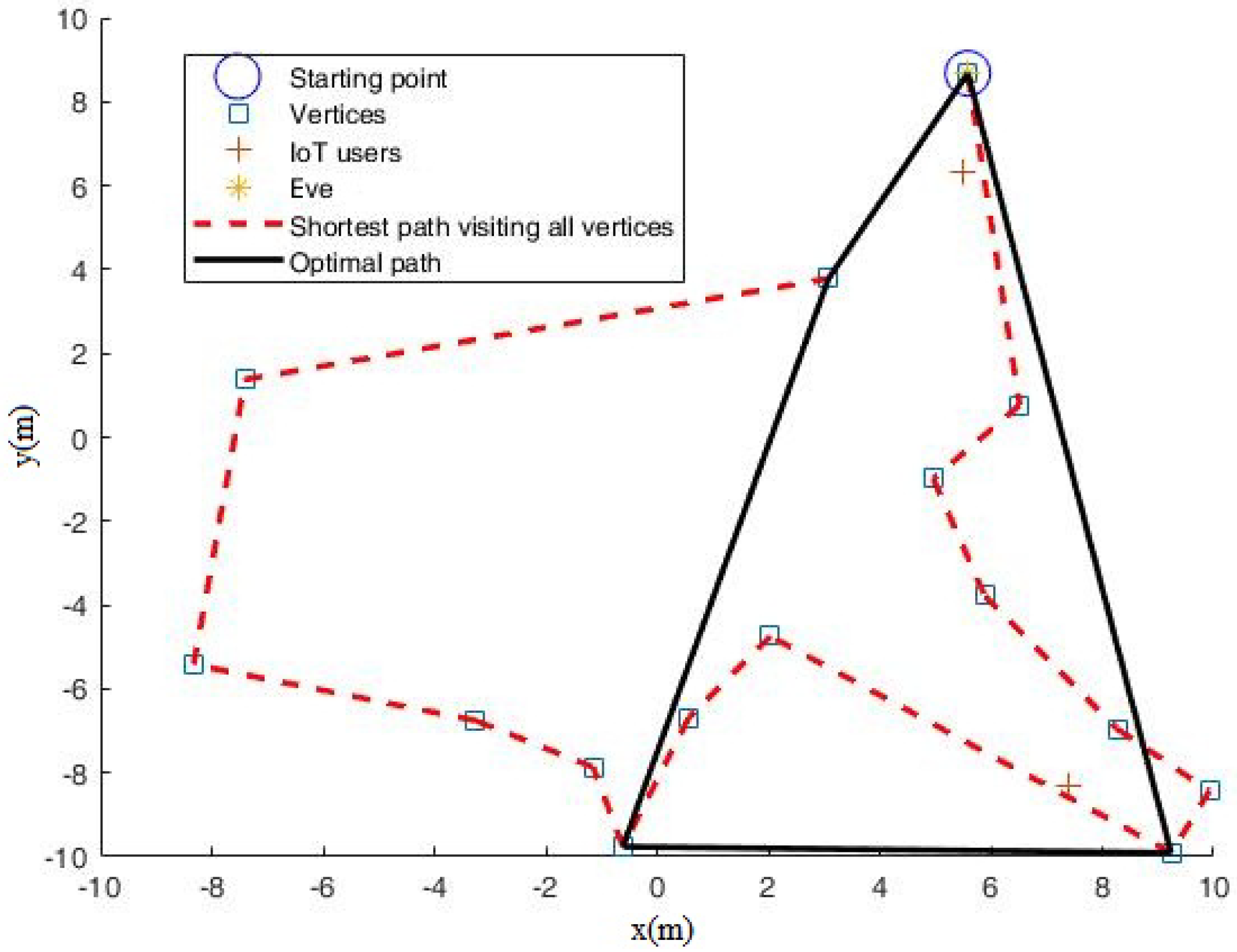
Furthermore, to show how the mobile relay scheme works effectively, we set dBm and obtained Figure 6. Compared with Figure 5 ( dBm), it can be seen in Figure 6 that the visiting path includes more far-way stopping points. This is because when the eavesdropper’s noise power is decreased, denoting that Eve has a stronger wiretap ability, the mobile relay has to move far way to guarantee secure transmission.
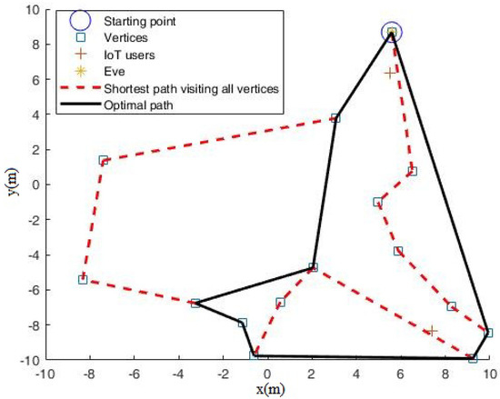
Figure 6.
Selected path for mobile relay with M = 15 when noise power dBm.
4. Discussion
In this section, we compare our proposed scheme and algorithms with state-of-the-art methods from the literature.
Unlike [1,2,3,4,5], which illustrate a four-terminal relay-eavesdropper network, there is no direct link between the source (Alice) and legitimate destination (Bob) in our system model due to the long distance between them and limited transmit power at Alice; therefore, the channel model and subsequent signal analysis are quite different from those in [1,2,3,4,5]. Moreover, in contrast to [2,3,4] with the relay’s location variation restricted in a line, the relay in our scheme moves around in a two-dimensional (2D) space, which is more complicated. In particular, unlike [3], where the relay assists the wire tapper rather than the destination, the mobile relay in our scheme helps the destination and suppresses the eavesdropper.
Our scheme presents moving trajectories, as shown in Figure 5 and Figure 6, which are not present in [7,8,9,10]. This is because [7,8,9,10] focus on fixed relay scenarios, in which relays are not able to move. Additionally, in contrast to [7], we obtain a competitive secrecy rate versus number of iterations. However, unlike [7], the secrecy rate of the fixed relay case in our scheme is near 0, which is depicted in Figure 4. This is because the eavesdropper in our paper is very close to the relay.
Refs. [11,12,13] aim to develop unmanned aerial vehicle(UAV)-based relay systems. They indeed provide flexible moving relays to implement air-to-ground or air-to-air wireless communication, while our ground mobile vehicle-based relay system is designed to solve the ground secure transmission problem, especially the indoor complicated pitch case. However, there are some identical issues both in UAV and in our ground mobile vehicle scheme, such as joint trajectory and communication design, which is generally formulated as mixed integer non-convex optimization problem, and this kind of problem is usually nontrivial to solve due to the integer constraints and other nonlinear parts. Contrary to expectations, we all utilize successive convex optimization techniques to solve the intractable optimization problem. Nevertheless, there are other different aspects among [11,12,13] and our scheme. Firstly, there is no eavesdropper in [11,13]; thus, it is not the maximum secrecy rate but the minimum communication delay in [11] and the maximum throughput in [13]. Secondly, multi-user communication scheduling and association in [13] are regarded as the integer constraints, while in our scheme, the integer constraints are the graph mobility model. Thirdly, Ref. [12] introduces an additional UAV-based jammer to ensure secure communication against eavesdropping. In comparison with [12], no jamming is added in our scheme, which leads to a notably different system model from that in [12]. Finally, unlike [11,12,13] employing the block coordinate descent method, we propose an iterative algorithm described as Algorithm 2 with Algorithm 1 embed in it, which is capable of obtaining a local optimal solution with much lower complexity.
A future research goal is to derive the secrecy rate bounds of the resource-constrained two-way mobile relay system. Additionally, finding the global optimal solution is a consequent work plan, and the secrecy rate with cache-aided at the mobile relay may also be worth investigation.
5. Conclusions
In the current study, the secrecy rate of a ground mobile vehicle-based relay system was investigated. Firstly, an integrated graph mobility model and a secrecy rate of the mobile relay system model were proposed. The joint secure transmission and graph mobility management problem was formulated to achieve secrecy rate maximization, subject to resource constraints and mobility graph structure constraints. Then, algorithms that achieve a local optimal solution were proposed. Simulation results were presented to demonstrate that our scheme outperforms the fixed relay scheme and that the mobile relay trajectory highly depends on noise power.
Author Contributions
Conceptualization and methodology: H.W.; software: H.W. and Y.W.; validation, formal analysis, investigation, resources, visualization, and writing—original draft preparation: H.W.; writing—review and editing: H.W. and Y.W.; supervision and project administration: M.W. All authors have read and agreed to the published version of the manuscript.
Funding
This research was funded by the Overseas Study Fund of Jiangsu University of Science and Technology grant number just-2018-05.
Acknowledgments
The authors are grateful to Yik-Chung Wu at the University of Hong Kong for providing the visiting researcher project; thank Shuai Wang (Southern University of Science and Technology) technique help; and acknowledge the funding support from Jiangsu University of Science and Technology.
Conflicts of Interest
The authors declare no conflict of interest.
Abbreviations
The following abbreviations are used in this manuscript:
| MINLP | Mixed integer nonlinear programming |
| UAV | Unmanned aerial vehicles |
| CSI | Channel state information |
| SNR | Signal-to-noise ratio |
| NSM | Neighborhood search method |
Appendix A
and are supposed to be optimal for P1; then, and must activate the constraint (10c), i.e., . Otherwise, we can increase the value of such that the left-hand sides of (11) and (12) are increased. This means that the objective value of P1 can also be increased, which contradicts being the optimal. Therefore, the constraint (10c) can be restricted to an equality .
Appendix B
Transformation from P1 to P2 with fixed .
With the fixed , an optimal solution to P1 activates (10a), (A1a), and (A1b), and the following holds:
(A2) shows that the objective function of P1 is a monotonically increasing function of ; the maximum value of in (A2) is obtained when are maximized. Since (22) holds, can be obtained, and maximizing is equal to obtaining the maximum value of ; therefore, problem P1 is equivalently transformed into P2.
References
- Lai, L.; Gamal, E.H. The relay eavesdropper channel: Cooperation for secrecy. IEEE Trans. Inf. Theory 2008, 54, 4005–4019. [Google Scholar] [CrossRef]
- Awan, Z.H.; Zaidi, A.; Vandendorpe, L. Secure transmission over parallel relay channel. IEEE Trans. Inf. Forensics Secur. 2012, 7, 359–371. [Google Scholar] [CrossRef] [Green Version]
- Yuksel, M.; Erkip, E. Secure communication with a relay helping the wire-tapper. In Proceedings of the IEEE Information Theory Workshop, Lake Tahoe, CA, USA, 2–6 September 2007; pp. 595–600. [Google Scholar]
- Awan, Z.H.; Zaidi, A.; Vandendorpe, L. Multiacess channel with partially cooperating encoders and security constraints. IEEE Trans. Inf. Forensics Secur. 2012, 8, 1243–1254. [Google Scholar] [CrossRef] [Green Version]
- Zaidi, A.; Vandendorpe, L. coding schemes for relay-assisted information embedding. IEEE Trans. Inf. Forensics Secur. 2009, 4, 70–85. [Google Scholar] [CrossRef]
- Wang, S.; Xia, M.; Huang, K.; Wu, Y.-C. Wirelessly powered two-way communication with nonlinear energy harvesting model: Rate regions under fixed and mobile relay. IEEE Trans. Wirel. Commun. 2017, 16, 8190–8204. [Google Scholar] [CrossRef]
- Xu, S.; Song, X.; Gao, Y.; Li, S.; Cao, i.; Xie, Z. Secrecy-Enhancing Design for Two-Way Energy Harvesting Cooperative Networks with Full-Duplex Relay Jamming. China Commun. 2021, 5, 273–284. [Google Scholar] [CrossRef]
- Wu, M.R.; Song, Q.Y.; Guo, L.; Jamalipour, A. Charge-Then-Cooperate: Secure Resource Allocation for Wireless-Powered Relay Networks With Wireless Energy Transfer. IEEE Trans. Vehicular Tech. 2021, 70, 5088–5093. [Google Scholar] [CrossRef]
- Yan, S.; Wang, X.; Li, Z.; Li, B.; Fei, Z. Cooperative Jamming for Physical Layer Security in Hybrid Satellite Terrestrial Relay Networks. China Commun. 2019, 12, 154–164. [Google Scholar] [CrossRef]
- Lu, X.; de Lamare, R.C. Opportunistic Relaying and Jamming Based on Secrecy-Rate Maximization for Multiuser Buffer-Aided Relay Systems. IEEE Trans. Vehicular Tech. 2020, 69, 15269–15283. [Google Scholar] [CrossRef]
- Bliss, M.; Michelusi, N. Trajectory Optimization for Rotary-Wing UAVs in Wireless Networks with Random Requests. In Proceedings of the 2019 IEEE Global Communications Conference (GLOBECOM), Waikoloa, HI, USA, 9–13 December 2019; pp. 1–5. [Google Scholar]
- Zhang, J.Y.; Wu, F.H.; Zhu, Y.T.; Xiao, L.; Yang, D.C. Joint trajectory and power optimization for mobile jammer-aided secure UAV relay network. Veh. Commun. 2021, 30, 10035. [Google Scholar]
- Qingqing, W.; Yong, Z.; Rui, Z. Joint Trajectory and Communication Design for Multi-UAV Enabled Wireless Networks. IEEE Trans. Wireless Commun. 2018, 17, 2109–2121. [Google Scholar]
- Wang, S.; Xia, M.; Wu, Y.-C. Joint Communication and Motion Energy Minimization in mobile ground vehicle Backscatter Communication. In Proceedings of the ICC 2019—2019 IEEE International Conference on Communications (ICC), Shanghai, China, 20–24 May 2019; pp. 1–6. [Google Scholar]
- Bondy, J.A.; Murthy, U. Graph Theory with Applications; Elsevier: New York, NY, USA, 1976. [Google Scholar]
- Mei, Y.; Lu, Y.H.; Hu, Y.; Lee, C. Deployment of mobile robots with energy and timing constraints. IEEE Trans. Robot. 2006, 22, 507–522. [Google Scholar]
- Shu, Y.; Yousefi, H.; Cheng, P.; Chen, J.; Gu, Y.; He, T.; Shin, K.G. Near-optimal velocity control for mobile charging in wireless rechargeable sensor networks. IEEE Trans. Mobile Comput. 2016, 15, 1699–1713. [Google Scholar] [CrossRef] [Green Version]
- Bertsekas, D.P. Network Optimization: Continuous and Discrete Models; Athena Scientific: Nashua, NH, USA, 1998. [Google Scholar]
- Gendreau, M.; Potvin, J.Y. Handbook of Metaheuristics, 2nd ed.; Springer: New York, NY, USA, 2010. [Google Scholar]
- Neumann, F.; Wegener, I. Randomized local search, evolutionary algorithms, and the minimum spanning tree problem. Theor. Comput. Sci. 2007, 378, 32–40. [Google Scholar] [CrossRef] [Green Version]
- Goldstein, L.; Waterman, M. Neighborhood size in the simulated annealing algorithm. Amer. J. Math. Manage. Sci. 1988, 8, 409–423. [Google Scholar]
- Boyd, S.; Vandenberghe, L. Convex Optimization; Cambridge Univ Press: Cambridge, UK, 2004. [Google Scholar]
- Laporte, G. The traveling salesman problem: An overview of exact and approximate algorithms. Eur. J. Oper. Res. 1992, 59, 231–247. [Google Scholar] [CrossRef]
- Belotti, P.; Kirches, C.; Leyffer, S.; Linderoth, J.; Luedtke, J.; Mahajan, A. Mixed-integer nonlinear optimization. Acta Numer. 2013, 22, 1–131. [Google Scholar] [CrossRef] [Green Version]
- Held, M.; Karp, R.M. A dynamic programming approach to sequencing problems. J. Soc. for Indust. Appl. Math. 1962, 10, 196–210. [Google Scholar] [CrossRef]
- Ben-Tal, A.; Nemirovski, A. Lectures on Modern Convex Optimization (MPS/SIAM Series on Optimizations); SIAM: Philadelphia, PA, USA, 2013. [Google Scholar]
- Wang, S.; Xia, M.; Wu, Y.-C. Multi-pair two-way relay network with harvest-then-transmit users: Resolving pairwise uplink-downlink coupling. IEEE J. Sel. Topics Signal Process. 2016, 10, 1506–1521. [Google Scholar] [CrossRef] [Green Version]


Publisher’s Note: MDPI stays neutral with regard to jurisdictional claims in published maps and institutional affiliations. |
© 2021 by the authors. Licensee MDPI, Basel, Switzerland. This article is an open access article distributed under the terms and conditions of the Creative Commons Attribution (CC BY) license (https://creativecommons.org/licenses/by/4.0/).