Article

A Study of Current Controlled Discharge in a Nitrogen Filled Tube

1
Faculty of Nuclear Sciences and Physical Engineering, Czech Technical University in Prague, Brehova 7, 115 19 Prague, Czech Republic
2
Institute of Physics ASCR ELI-Beamlines, Za Radnici 835, 252 41 Dolni Brezany, Czech Republic
3
Faculty of Biomedical Engineering, Czech Technical University in Prague, Sitna 3105, 272 01 Kladno, Czech Republic
4
Keldysh Institute of Applied Mathematics RAS, Miusskaya 4, 125047 Moscow, Russia
*
Author to whom correspondence should be addressed.
Appl. Sci. 2021, 11(21), 10253; https://doi.org/10.3390/app112110253
Submission received: 10 September 2021 / Revised: 8 October 2021 / Accepted: 26 October 2021 / Published: 1 November 2021
(This article belongs to the Special Issue Recent Advances in Plasma Technology and Applications)

Abstract

:
Time dependencies of the electrical resistance and electron density evolution in the discharge in a tube, with nitrogen at different pressures, with a diameter of 9.2 mm and a length of 10 cm were studied. A current pulse with an amplitude of 500 A and duration of 10 μ s has created the discharge in the tube. Instantaneous electron densities are estimated from the interference pattern in Mach–Zehnder interferometer using femtosecond Ti: sapphire laser beam. Laboratory results are compared with results of computer modelling by MHD computer codes NPINCH and ZSTAR. Time development of the discharge resistance according to experiment is measured and evaluated. Minimum measurable value of the electron density in the experiment is determined as 2 × 10 15 cm 3 .

1. Introduction

The basic subject of our interest is the temporal development of plasma excited by an electric discharge in a tube filled with nitrogen, in order to create conditions suitable for recombination excitation of a laser at quantum transitions of hydrogen-like nitrogen [1]. During the pulse discharge development, it is necessary to ionize fully the plasma and then to cool the plasma rapidly. Using the computer modelling method, we have shown that the required conditions can be set in a pinching discharge in a non-ablative capillary with a diameter of 3 mm filled with nitrogen to the pressure of 500 Pa excited by a current pulse with amplitude 50 kA and duration 80 ns . Experiments with parameters corresponding to the formulated requirements were performed in several laboratories, and laser activity was not achieved [2,3,4,5]. We have come to the conclusion that in capillaries with such a high electric current, the wall ablation becomes a significant process [6]. We assume that to suppress the effect of ablation on the dynamics of plasma heating, the capillary diameter, and the current pulse shape should be modified, or additional plasma heating with a laser beam should be applied [7]. In order to suppress the ablation of the wall, we propose to increase the tube diameter by factor 2–4 and to use three consecutive independent current pulses. The first one (so called “pre-ionization”) will ignite the discharge and prepare uniform and stable plasma column with high percentage of the first ionization state abundance. The second pulse (“pedestal”) should be high and fast enough to create a magnetic pressure sufficient to force the plasma to detach from the wall, but not too high in order to keep the current below the tube wall ablation threshold. The final fast high current pulse (“main”) can be then set according to the non-ablative computer modelling. In this paper, we focus on the first (pre-ionization) stage and we present a comparison of laboratory experiments and computer simulations of these experiments aimed at determining the spatial distribution of electron density and temperature together with resistance of the plasma-discharge column for slow pre-ionization discharge.
The role of small (hundreds of Ampere) pre-ionization current lasting several μ s was described in several articles. Initially, the small pre-ionization current less than 16 A was used mainly to stabilize the plasma fiber [8,9]. Antsiferov and Dorokhin investigated [10] the influence of pre-ionization on the shock wave motion in an alumina tube with 6 mm diameter and 10 mm length. The working gas was Ar with the range of initial pressures 80–320 Pa . No visible influence of the pre-ionization was observed for the current less than 50 A . Faster evolution of the shock wave and earlier start of the shock wave were observed for the pre-ionization current with exponentially decaying sinusoidal shape with quarter period of 500 ns , I m a x = 2500 A , and t d = 4 μ s . Computer simulation [11] suggests that pre-ionization current may redistribute plasma mass density to parabolic density profile with maximum along capillary wall, which has an effect on plasma evolution during subsequent main discharge action. It seems that it is possible to change plasma condition for lasing. A similar effect was observed for the argon laser in a few laboratories, the pre-pulse (or pre-ionization) current influences plasma dynamics, subsequently laser intensity, beam profile, divergence, and the length of the laser pulse [12,13]. (There, it is shown that plasma is escaping through open capillary ends during μ s times of pre-ionization and its initial mass density is reducing.) Sakamoto et al. [14] demonstrated how time delay between triggering pre-pulse and main pulse improves gain of an argon laser and shifts time of the pinch onset.
We optimize the tube discharge system for recombination excitation of the nitrogen laser via computer modelling. We vary electric current, tube diameter and initial pressure. This paper presents a comparison of experimental and modelling results for selected, atypical parameters, i.e., study a relatively large tube diameter and a relatively long current pulse. Their mutual agreement supports the further use of our computer method of system optimization.

2. Materials and Methods

The basis of our experimental setup is in Figure 1. We studied the discharge in an alumina tube with inner diameter 9.2 mm and length 10 cm , filled with nitrogen at a pressure P = ( 30 , 70 , 100 , 130 , 300 ) Pa . From both sides, the tube is terminated by electrodes sealed by 1 mm thick BK7 optical windows. Gas is filled through a hole in the grounded electrode. The discharge current with the amplitude slightly less than 500 A is formed by a discrete Pulse Forming Line and switched by a t 1 spark gap to the load. The tube is placed in one arm of Mach–Zehnder interferometer illuminated by 800 nm , 60 fs pulses from Ti:Sapphire laser. The fringe pattern produced by interferometer is recorded by a CCD camera and measured phase shift allows us to deduce the radial profile of electron density at the moment of passage of fs laser beam (see Appendix A). The diagnostic femtosecond laser is fired with a selected delay after the start of the current pulse. Discharge current is measured using a pulse current transformer placed around grounding cable. Voltage between electrodes is measured using two Tektronix P6015A probes with common floating grounds. The voltage on the tube’s high voltage electrode before gas breakdown is 40 kV . After gas breakdown, it drops to several hundreds volts. In order to get better voltage measurement resolution during discharge, we set the oscilloscope to low volts per division settings. To protect the oscilloscope from excessive voltage at this setting, we limit the voltage on the P6015A probe input using 10 k Ω resistor connected to the HV electrode in series with 800 V transil connected to the ground.
The tube dimensions choice ( 0.92 × 10 ) cm was limited by the design of the last (main) pulse driver unit, which was build in our laboratory, and is not discussed in this paper. Filling pressure range P = ( 30 , 70 , 100 , 130 , 300 ) Pa was chosen around pressure P = ( 70 ÷ 130 ) Pa , where we expect optimal condition for our three stage laser system by preliminary computer simulations, plus two outlaying values P = ( 30 and 300 ) Pa . According to our preliminary simulations, the pre-ionization discharge current of amplitude I = 500 A and length of several μ s is sufficient to set suitable pre-ionization condition (as discussed in Section 1) and was extended to 10 μ s in order to study pre-ionization plasma evolution in longer timescale.

2.1. Tube Discharge Dynamics Modelling

The investigated discharge dynamics is also modeled using computer MHD codes NPINCH and ZSTAR. Simulation results are compared with results of laboratory experiments. The measured time dependence (Figure 1) of electric current passing through the tube serves as a driving force for both codes (see Figure 2).

2.1.1. NPINCH Code

The code NPINCH is a time dependent one-dimensional code, modelling the time evolution of the radial distributions of plasma parameters. The 1D approximation is considered owing to the large length-to-radius ratio. Approximation of two-temperature (ion and electron) one-fluid magnetohydrodynamics is used. The plasma is considered as highly collisional, with typical mean free paths of particles being much less than discharge diameter. Thus, magnetohydrodynamic approximation to describe plasma dynamics is applicable. The dissipative processes of electron thermal conductivity, Joule heating, Nernst and Ettinghausen effects, the radiation losses and ion viscosity are taken into account by the code [6,15]. The expressions for the dissipative coefficients are taken from [16], where they were obtained for the case of a plasma with an arbitrary mean value of the ion charge and the possible considerable difference between the Coulomb logarithms for electron–electron and electron–ion collisions. The local thermodynamic equilibrium (LTE) approximation is assumed to calculate ionization, pressure and specific internal energy of plasma. At low temperatures, as long as the mean ion charge is less than unity, there is a noticeable fraction of neutral particles in the plasma. We re-normalize the electron-ion collision frequency by taking into account a contribution of neutral particles to the electron scattering. Code NPINCH was used previously in [1,16,17,18,19,20,21,22] for simulations of dense Z-pinches as well as capillary discharges. In the considered discharge the plasma pressure is much higher than magnetic field pressure. Thus, the discharge will expand, if it would be not bounded by a dielectric tube. The dielectric tube bounding the discharge is considered as a passive motionless wall, implemented in the model by the two boundary conditions. Radial plasma velocity at the boundary vanishes, whereas its temperature is much less than typical temperature of the discharge plasma. More sophisticated description of plasma-wall interaction in these conditions was considered for example in [6,18] and in the references therein.

2.1.2. ZSTAR Code

The ZSTAR magnetohydrodynamic code is developed to model a multi-charged ion plasma in a two-dimensional axially symmetric geometry, taking into account ionization and emission processes [23,24]. The plasma dynamics are considered self-consistently with a non-equilibrium radiation field. Such an approach requires the approximation of radiative magnetohydrodynamics (RMHD). The properties of plasma radiation, ionization and equations of state, as well as excitation and ionization, and plasma kinetic coefficients are calculated by interpolation from a set of tables, prepared during preliminary processing. Such a procedure allows the code to avoid online calculations of absolutely different processes, such as plasma dynamics, atomic physics and ion kinetics. For dissipative coefficients, standard Braginskii expressions were incorporated. A detailed description can be found in [24].

3. Results

3.1. Measured Time Dependence of Plasma Column Resistance

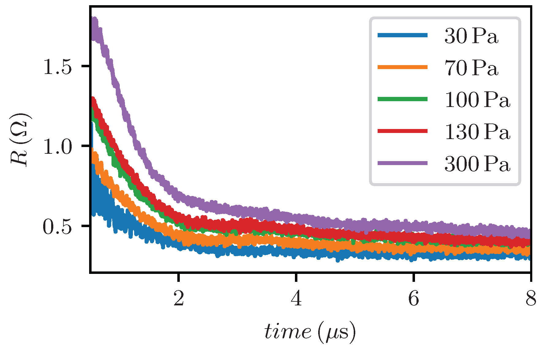
Simultaneous measurement of current and voltage on the discharge column allows us to express the time dependence of the resistance of the discharge column. Results in the range from 0.5 μ s to 8 μ s for initial nitrogen pressures in the range from 30 Pa to 300 Pa are shown in Figure 3. For higher initial gas pressure values, resistances are higher, namely nearer the beginning of the discharge. Resistances are evaluated from time t 0.5 μ s since there was a high electromagnetic interference on voltage probes at the time of spark-gap and tube breakdown.

3.2. Measured Electron Density Radial Profiles

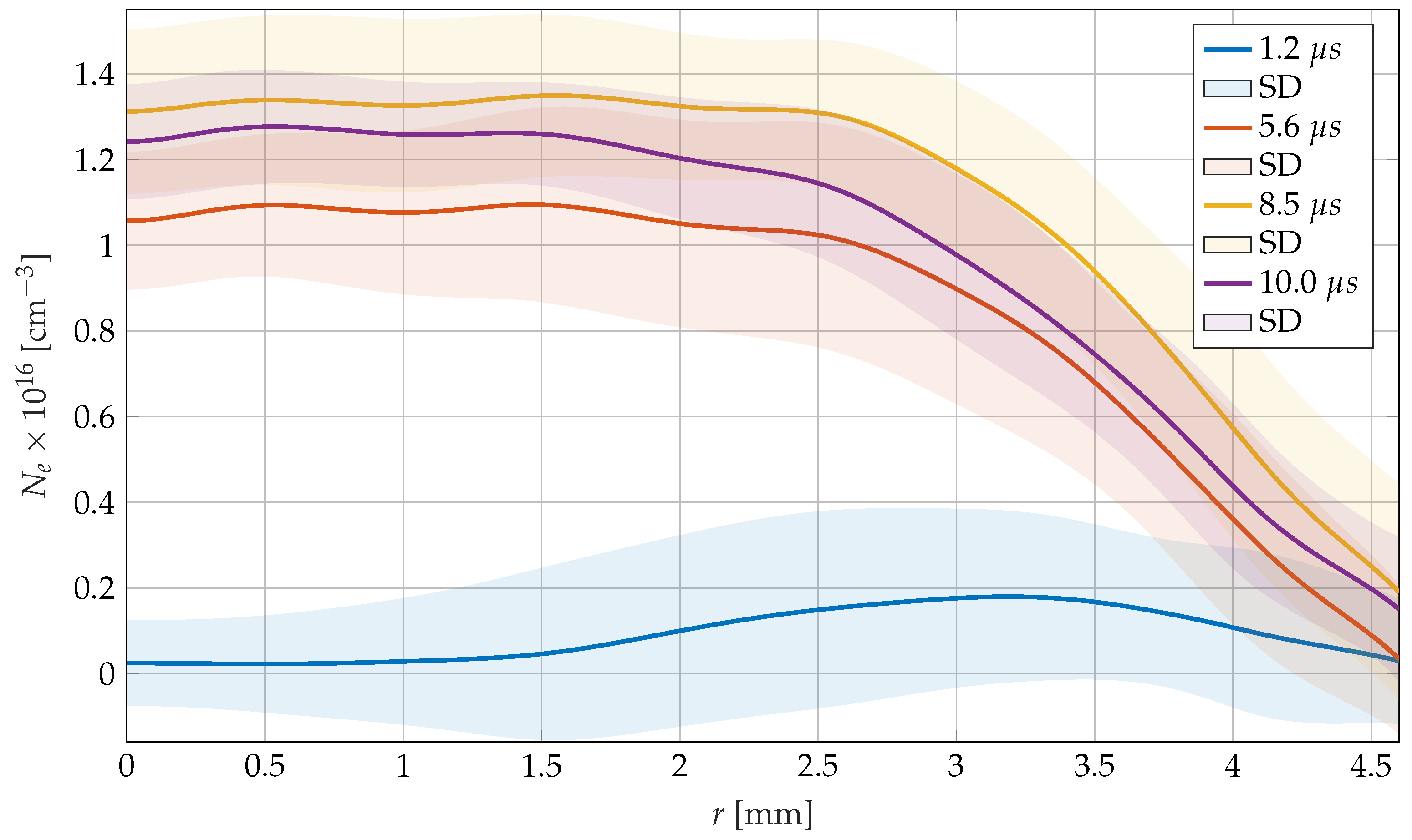
Basic plasma parameters, i.e., characteristic electron temperature of 2 eV and electron density of 2 × 10 16 cm 3 (as a simulations result shown later in Section 3.3) allow us to estimate that at most 2 times ionized nitrogen atoms are present in the discharge. These ions do not have an absorption line near the wavelength 800 nm of the femtosecond laser. Thus, we assume that the refractive index of the medium is given only by the electron density. Our experimental method of measuring the electron density allows us to measure values higher than 2 × 10 15 cm 3 . Representative radial profiles of electron density, determined by longitudinal interferometry for selected time points during the current pulse, can be seen in Figure 4. Each profile is a ten measurements mean value and a standard deviation. Fringe processing technique and 2D phase images are in Appendix A. It should be noted, that we are able to measure only the difference of the electron density inside the tube, not the absolute value. This is due to the fact, that all the diagnostic beam passed through the tube, so there was no zero fringe shift reference.

3.3. Modelling of Laboratory Experiments

Below we discuss results of simulations by two MHD codes, NPINCH and ZSTAR, which describe the behavior of plasma in magnetic field. These codes permit us to obtain all plasma parameters, magnetic and electric fields. We assume that the tube is pre-filled with non-ionized nitrogen gas of uniform density and temperature. The discharge is initiated by a pulse of current driven by an external circuit. After the breakdown, we can consider the total electric current to be a given function of time. We use the experimentally measured dependence of electric current (Figure 1b) on time to describe this function. Simulations have been performed for tube made from alumina with inner radius of 4.6 mm , filled by nitrogen at various pressures ( 30 , 70 , 100 , 130 , 300 ) Pa .
The initial breakdown of the discharge cannot be described by our models because the breakdown exhibits three-dimensional structure, and the effects of plasma non-quasi-neutrality are important. However, the initial stage is short compared with the full time of the discharge, and it does not affect the plasma parameters at later time. After the breakdown, the current pulse heats the plasma and creates an azimuthal component of the magnetic field. The plasma pressure is much higher than the magnetic field pressure. Simulations show that magnetic field pressure is more than ten times less than the plasma pressure. In the absence of the wall plasma would expand and not hold on in the initial radius.
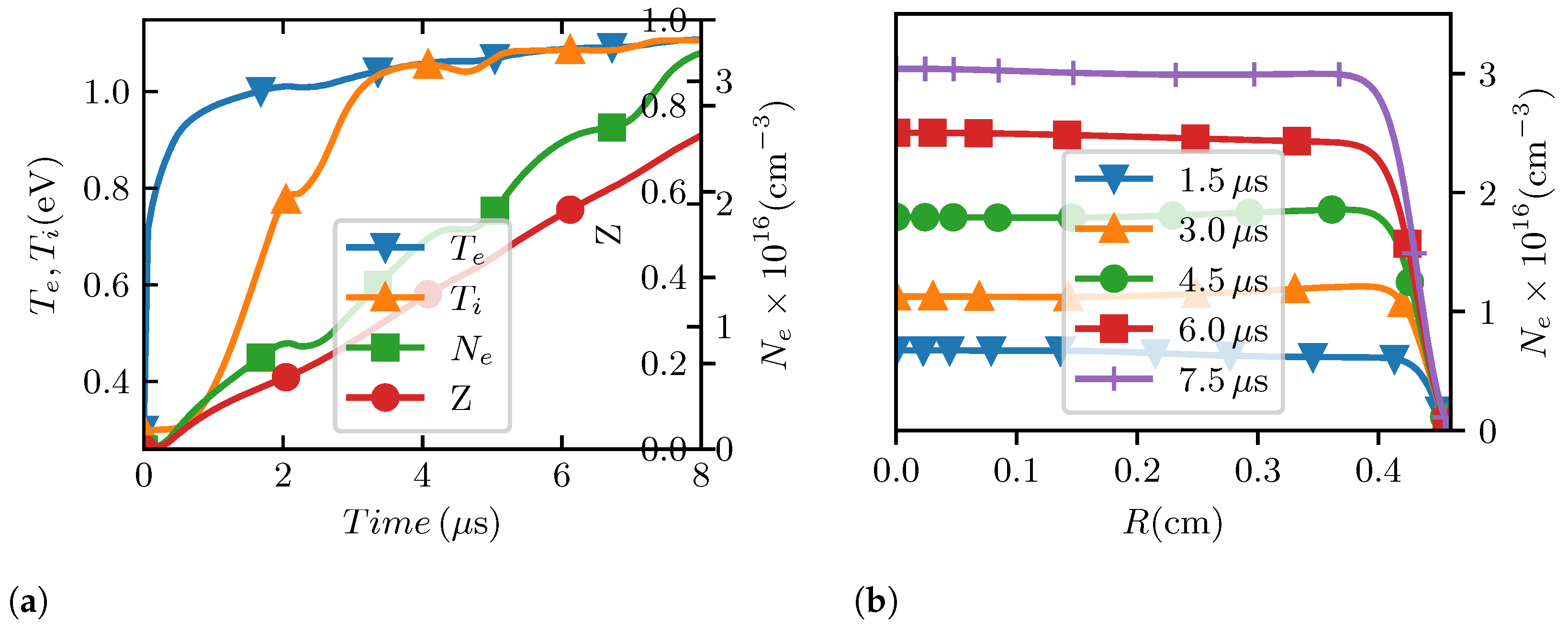
At first, as the electric current increases, the electron temperature T e grows with time up to the order of 1 eV . It happens, approximately, when electric current reaches its maximum value. Due to energy exchange between ions and electrons, ion temperature is slowly growing and becomes equal to electron temperature at approximately 3 μ s . Then, up to the end of discharge, both electron and ion temperatures grow very slowly. Almost all the energy of the discharge is spent on ionization of the tube filling gas. The electron density is growing till the end of the current pulse. The characteristic time of the penetration of electric field in plasma, the skin time t σ = 4 π σ R 0 2 / c 2 , is much less than the hydrodynamic time t h = R 0 / c s , where c s = ( z T e + T i ) / m i is the ion sound velocity, m i is the nitrogen ion mass, σ is plasma conductivity and c is velocity of light. As a result, the radial distribution of the electric field and electric current density are homogeneous and consequently, the plasma is heated and ionized locally. The radial profiles of plasma pressure, electron temperature and density are flat everywhere except near the wall. The plasma is cooled near the wall due to thermal conduction to the relatively cold tube wall. We see that due to the Ohmic heating, the plasma is ionized, and its electron density is growing, its radial profile is staying flat. The thermal conduction is not significant in the tube except region near the wall.

3.3.1. Discharge Plasma Evolution According to NPINCH

The temporal evolution of the electron density on the axis and electron and ion temperatures, degree of ionization are plotted in Figure 5a, showing that the electron density on the axis is growing. The axial electron and ion temperatures become equal at t 3 μ s , and then are found to increase slowly with time. The radial distributions of electron density at different moments of time are plotted in Figure 5b. The radial distributions of electron density are flat, except the region near the cold wall, where electron density drops. In one-dimensional simulations, we do not take into account longitudinal plasma flow.

3.3.2. Discharge Plasma Evolution According to Two-Dimensional Code ZSTAR

The ZSTAR code allows for obtaining plasma parameters as well as the electrical and magnetic fields in the whole space of the tube and electrodes. Using two-dimensional code ZSTAR and Tecplot [25] for the same experimental conditions, we obtain spatial distributions of basic plasma quantities inside the tube for any selected time during the discharge. Representative spatial distributions of electron density N e and temperature T e for initial pressure of 100 Pa at t = 5.6 μ s are shown in Figure 6.
The peak value of the electron density N e in the central part of the tube is 2.4 × 10 16 cm 3 . Along axis, plasma is almost homogeneous except the regions near both electrodes. The length of the homogeneous column of plasma is about 7 cm . Electron density drops towards both electrodes. In the region near the electrodes the electron temperature is higher than in the central region of the tube due to higher electric current density here, see Figure 6b. Near the wall, the electron temperature decreases sharply.

3.3.3. Estimation of Plasma Resistance According to NPINCH Code

The resistance R of the plasma column of the length d can be evaluated as
R ( t ) = E ( t ) d I ( t ) ,
where E ( t ) is the electric field and I ( t ) is the electric current passing through the tube. The simulations (NPINCH) for various initial gas pressures allow us to evaluate time dependencies of resistance R ( t ) . The results are shown in Figure 7.
It is well known that the resistance is controlled primarily by the plasma temperature and only slightly by the plasma density. The simulations show that tube in these simulations are of the same order. In the experiment and in the simulations we see the same dependence on initial pressure, the resistance is higher for higher pressure. However, the differences between the resistance values for various pressures are much less for simulations than for experiment.

3.3.4. Evaluation of the Instantaneous Plasma Resistance Using ZSTAR Code

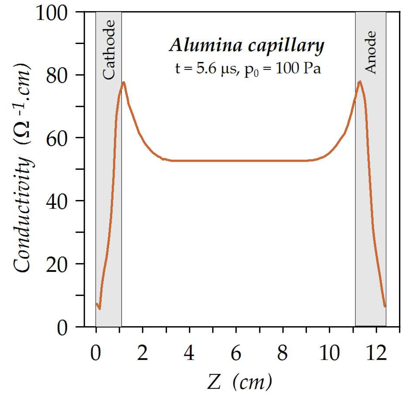
We also evaluate the tube resistance from two-dimensional simulations by code ZSTAR. If the plasma electron density N e ( r , z ) and temperature T e ( r , z ) are known, the local value of plasma conductivity σ ( r , z ) may be estimated [6,16]. Then for each value of coordinate z we found the electrical column conductivity
Σ ( z ) = 0 R 0 2 π σ ( r , z ) r d r ,
where R 0 = 0.46 cm is the tube radius (Figure 8). Plasma resistivity is lower in the vicinity of electrodes due to higher electron temperature in this region (see Figure 6b).
The total plasma resistance R is estimated as the integrated value of the resistivity on the interval between the tube electrodes. The evaluated resistance is R Z S T A R = 0.22 Ω . This value is lower than the value, obtained in NPINCH simulations. It is due to the higher temperature obtained in ZSTAR simulations.

3.3.5. Evaluation of Wave Phase Difference Φ in Mach–Zehnder Interferometer

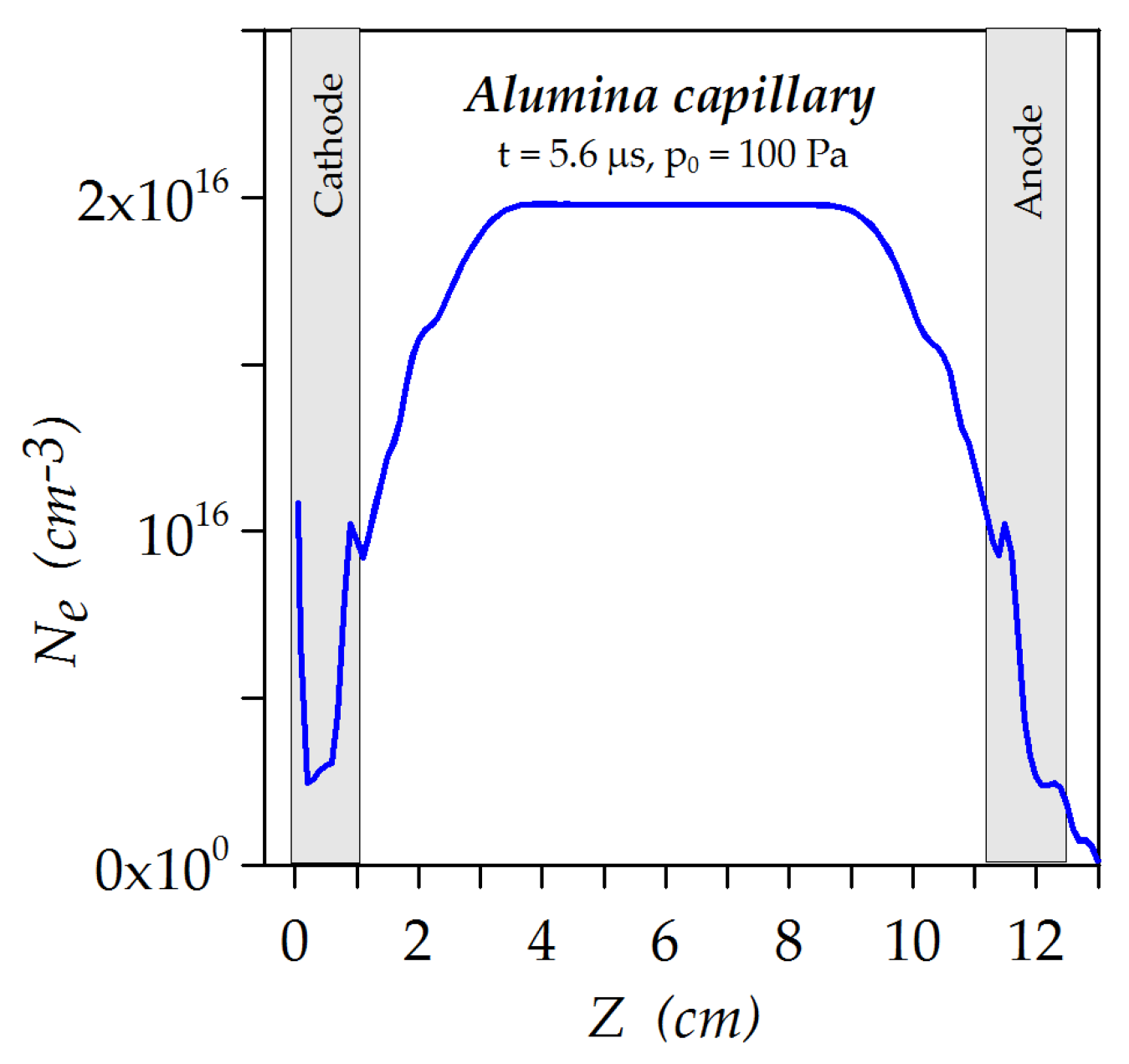
The spatial distribution of the electron density N e ( r , z ) , as follows from the ZSTAR simulation, allows us to predict the phase difference Φ ( r , z ) observed in Mach–Zehnder interferometer. For example, the evaluated electron density N e ( 0 , z ) on the tube axis for initial pressure 100 Pa at time t = 5.6 μ s is shown as Figure 9.
The phase shifts Φ ( 0 , 0 ) of the beam passing through the tube in this case is given by the integral
Φ ( 0 , 0 ) = π λ 1 N c N e ( 0 , z ) d z = 4.4 rad
and corresponds to the averaged electron density.

3.3.6. Time Dependencies of Electron Density Evaluated and Measured

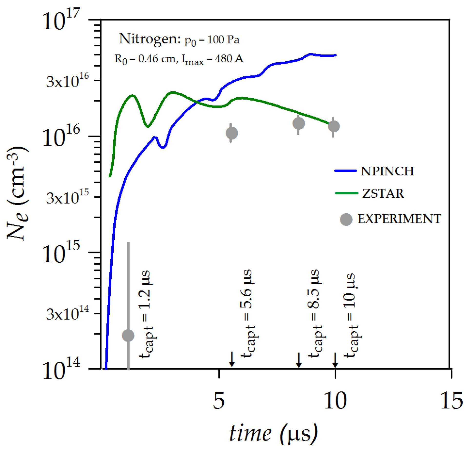
Due to the fact that the tube has a length to diameter ratio of more than 10, we compare the plasma quantities on the axis evaluated by one dimensional NPINCH code and quantities in the center of the tube, evaluated by ZSTAR code. The time evolution of plasma electron density N e is shown in Figure 10. The blue line in Figure 10 shows the characteristic electron density evolution given by NPINCH code. The electron density increases almost monotonically with increasing time. The green line in Figure 10 shows the electron density evolution, given by ZSTAR code. The electron density has a peak value at 1.2 μ s , then it decreases up to the end of the discharge due to the outflow of plasma through the open ends of the tube. Experimentally estimated average along tube length values of electron density N e for four selected moments of time, based on interference recording in Mach–Zehnder interferometer, are shown by gray circles in Figure 10. In the experiment, the electron density is growing during the discharge, but its growth rate is diminishing after 5.6 μ s . It means that after plasma outflow in Z direction plays some role. In NPINCH simulations, the outflow is not taken into account. The experimental values of the average electron density are lower than the calculated values on the tube axis. The discrepancy between experimental and simulated results can be explained by several reasons. The average along tube length electron density is lower than the one on the axis in the central part of the tube due to the density drop near electrodes.

4. Discussion and Conclusions

To obtain conditions suitable for recombinational excitation of a laser in a tube filled with nitrogen it is necessary to suppress ablation of the walls. For this purpose, we use wider tube and we modify the current pulse shape. The first step is to organize pre-ionizaton. The main purpose of the pre-ionization is to prepare a stable plasma column before the Z-pinching discharge. Time evolution of the pre-ionization discharge with parameters, obtained according simulation results, is studied. We perform preliminary simulations of the discharge dynamics in the tubes of different diameters and for electric current amplitudes in the range 300–500 A. These simulations permit us to choose optimal parameters for the experimental design. Time dependencies of plasma resistance and plasma electron density and spatial density distributions are estimated. Experimental and simulated results are compared.
We compare the electron density measured in experiment and the electron density simulated by codes NPINCH and ZSTAR. Experimental values of the average electron density are slightly lower than calculated values on the tube axis. Here, it should be noted again, that we measure the difference of the electron density inside the tube, and we assume a zero electron density at the tube wall (see Figure 4). Simulated and experimental radial profiles of the electron density are flat, except the region near the wall. Two-dimensional simulations show, that the electron density is uniform in the Z direction except the region near electrodes.
We compare also the tube resistance, measured in experiment, and simulated by two codes for filling gas pressure 100 Pa at the time moment 5.6 μ s . In the experiment R e x p = 0.45 Ω , simulations by NPINCH code give R N P I N C H = 0.35 Ω , by ZSTAR code give R Z S T A R = 0.22 Ω . The differences between the results obtained by the different codes is caused mainly by different electron temperatures, obtained in the simulations. This difference is explained by different models of ionization and influence of neutral particles, especially when the degree of ionization is small Z < 1 . The experiment and the simulations give practically the same dependencies on initial pressure, the resistance is higher for higher pressure. Obtained results can be used for further modelling and experimental study of pinching plasma laser pumping in a tube filled with nitrogen.
We estimated a possible growth rate of the dissipative MHD instability typical for Z-pinch. The estimation gives growth rate ∼100 s 1 . It is too low to see such instability. The effect of the pre-ionization on the Z-pinch stability will be evaluated in the next interferometric experiment.

Author Contributions

Conceptualization, M.N., J.H. and A.J.; software, P.V., P.S. and J.S.; formal analysis, J.S.; investigation, M.N., J.H., N.B. and A.J.; resources, A.J.; data curation, M.N.; writing—original draft preparation, M.V., J.S. and N.B.; writing—review and editing, M.N., J.S., P.V. and N.B.; visualization, M.N., J.S. and P.V.; funding acquisition, A.J. All authors have read and agreed to the published version of the manuscript.

Funding

This research was funded by Ministry of Education Youth and Sports of Czech Republic (MEYS CR) grant numbers LTT17015 and CZ.02.1.01/0.0/0.0/16_019/0000778 and by the project High Field Initiative (CZ.02.1.01/0.0/0.0/15_003/0000449) from European Regional Development Fund (HIFI).

Institutional Review Board Statement

Not applicable.

Informed Consent Statement

Not applicable.

Data Availability Statement

Not applicable.

Acknowledgments

Authors are grateful to S.V. Zakharovfor making it possible to use the ZSTAR program to simulate the experiment and for helping us with the calculations performed.

Conflicts of Interest

The authors declare no conflict of interest. The funders had no role in the design of the study; in the collection, analyses, or interpretation of data; in the writing of the manuscript, or in the decision to publish the results.

Appendix A. Optical Diagnostics of the Discharge
Based on the analysis of interference patterns from the Mach–Zehnder interferometer, the discharge electron density in the discharge column is estimated. The refractive index n of the plasma is given by the instantaneous discharge electron density Ne:
n = 1 N e N c 1 1 2 N e N c ,
where N c is the critical electron density for an electromagnetic wave with a angular frequency ω = 2.356 × 10 15 s 1 ( λ = 800 nm ):
N c = ε m e ω 2 e 2 = 1.744 × 10 21 cm 3 .
We assume that the waves in both arms of the interferometer propagate along the z-axis. The period of the recorded interference pattern is given by the set angle α between the beams passing through the different arms of the interferometer. The ideal shape of the recorded interference patterns is proportional to the function
1 + cos π α x λ + Φ ( x , y ) .
The phase difference Φ ( x , y ) , which is recorded after passing through the arms of the Mach–Zehnder interferometer, is determined by the integral
Φ ( x , y ) = π λ N c 0 d N e ( x , y , z ) d z ,
or
Φ ( x , y ) = π d λ N e ¯ N c ,
if the mean value of electron density N e ¯ along the path is introduced. In our case, the angle α between the beams was set to about 2.4 mrad (about 30 strips per tube diameter). The phase shift Φ would significantly affect the interference pattern if its value is comparable to 2 π .
We recorded the interference pattern and determined the phase difference as follows. We have used a code for an interferogram evaluation based on Fourier transform [26]. An interferogram can be represented in a mathematical formula as:
g ( x , y ) = a ( x , y ) + b ( x , y ) · cos 2 π f 0 x + Φ ( x , y ) .
Functions a ( x , y ) and b ( x , y ) denote a fluctuating background and an amplitude, respectively, f 0 , is a spatial frequency of a fringe pattern and Φ ( x , y ) represents a phase shift which can be extracted by method proposed by Takeda et al. [26]. The crucial method assumption of slowly varying functions a ( x , y ) , b ( x , y ) , Φ ( x , y ) was fulfilled. For each measurement, a reference and signal interferogram was recorded and evaluated. The reference phase was subtracted from the signal one and unwrapped. The diagnostic beam passed through the tube filled with gas/plasma. However, there was no region of plasma free medium. For this reason, we assumed from acquired data that the amount of electron density was negligible near to the tube walls and set to zero value. This assumption could cause an inaccuracy in determination of an absolute value of electron density. This might be neglected, because from our measurement, the maximal phase shift tended to be localized in the tube center.
To obtain the electron density spatial distribution, it had to be assumed that the plasma in a tube is cylindrically symmetrical. On the other hand, we can consider the electron density to be averaged, as was expressed in the text earlier. The average electron density can be calculated as
N e ¯ ( x , y ) = N c λ 0 d Φ ( x , y ) π .
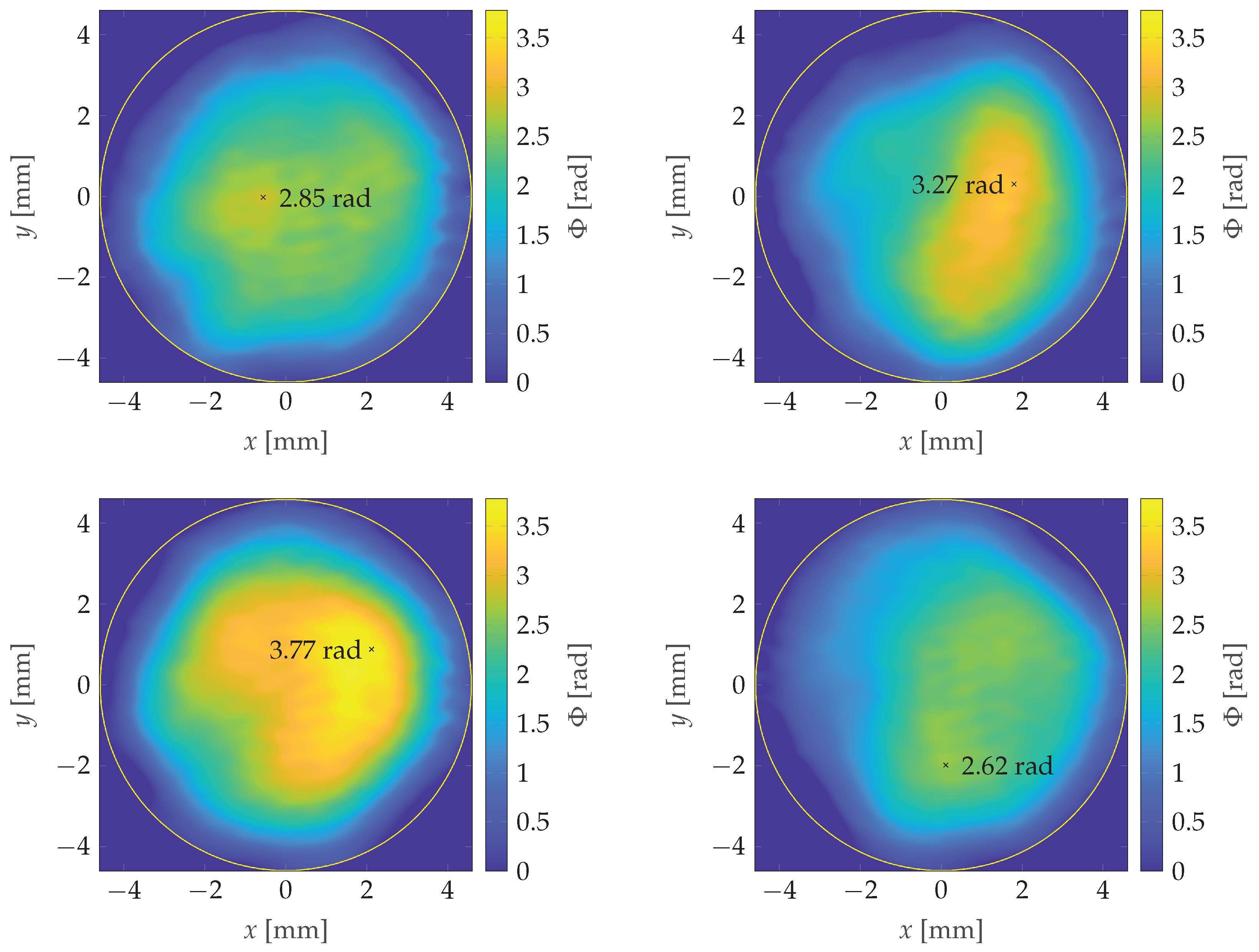
The acquired dependencies of the phase shift Φ ( x , y ) in repeated shots under the identical initial and boundary conditions are seen in Figure A1. They are not identical. The stochastic nature of the results may be interpreted either by the stochastic nature of the electron distribution in the discharge or by the inaccuracy of the interference pattern data recording and subsequent data processing.
We performed reference measurement of Φ ( x , y ) in a case without discharge in the tube. In such an ideal case, the phase shift Φ ( x , y ) should be zero. During repeated shots, we received a random function Φ ( x , y ) with amplitudes ± 0.5 rad . If the discharge tube length d = 10 cm , laser wavelength λ = 800 nm is used, the critical electron density N c = 1.744 × 10 21 cm 3 and averaged electron density N e = 4.43 × 10 15 Φ . If we estimate the accuracy of the phase determination as 0.5 rad , the accuracy of the electron density determination is 2.2 × 10 15 cm 3 . Interference observed with our Mach–Zehnder experiment are recorded by femtosecond laser pulse, triggered with a defined delay after the beginning of the electrical discharge. Consequently, we can estimate instantaneous phase shifts Φ and instantaneous average electron density N e ( x , y ) at selected moment of the discharge.
Figure A1. Spatial distributions of the phase shift Φ ( x , y ) inside the tube resulted in 4 consecutive shots with the highest values marked.
Applsci 11 10253 g0a1

References

  1. Vrba, P.; Vrbová, M.; Bobrova, N.; Sasorov, P. Modelling of a nitrogen x-ray laser pumped by capillary discharge. Centr. Eur. J. Phys. 2005, 3, 564–580. [Google Scholar] [CrossRef]
  2. Kampel, N.; Rikanati, A.; Be’ery, I.; Ben-Kish, A.; Fisher, A.; Ron, A. Feasibility of a nitrogen-recombination soft-x-ray laser using capillary discharge Z pinch. Phys. Rev. E 2008, 78, 056404. [Google Scholar] [CrossRef] [PubMed]
  3. Sakai, Y.; Rosenzweig, J.; Kumai, H.; Nakanishi, Y.; Ishizuka, Y.; Takahashi, S.; Komatsu, T.; Xiao, Y.; Bin, H.; Quishi, Z.; et al. Observation of emission process in hydrogen-like nitrogen Z-pinch discharge with time integrated soft X-ray spectrum pinhole image. Phys. Plasmas 2013, 20, 023108. [Google Scholar] [CrossRef]
  4. Nevrkla, M.; Jančárek, A.; Nawaz, M.; Parkman, T.; Vrbová, M. Time-resolved EUV spectra from nitrogen Z-pinching capillary discharge. In EUV and X-ray Optics: Synergy between Laboratory and Space IV; Hudec, R., Pina, L., Eds.; International Society for Optics and Photonics, SPIE: Cardiff, UK, 2015; Volume 9510, pp. 302–309. [Google Scholar] [CrossRef]
  5. Barnwal, S.; Nigam, S.; Aneesh, K.; Prasad, Y.; Sharma, M.; Tripathi, P.; Joshi, A.; Naik, P.; Vora, H.; Gupta, P. Exploring X-ray lasing in nitrogen pinch plasma at very high and fast discharge current excitation. Appl. Phys. B 2017, 123, 178. [Google Scholar] [CrossRef]
  6. Vrbova, M.; Vrba, P.; Jancarek, A.; Nevrkla, M.; Bobrova, N.A.; Sasorov, P.V. Wall ablation effect on the recombination pumping of EUV laser in pinching capillary discharge. Phys. Plasmas 2019, 26, 083108. [Google Scholar] [CrossRef]
  7. Vrba, P.; Sasorov, P.; Bobrova, N.; Jančárek, A.; Vrbová, M. Hybrid pumping of EUV nitrogen laser. In Proceedings of the Conference on HIgh Intensity Laser and Attosecond Science in Israel, Tel Aviv-Yafo, Israel, 9–11 December 2019. [Google Scholar]
  8. Hayashi, Y.; Xiao, Y.; Sakamoto, N.; Miyahara, H.; Niimi, G.; Watanabe, M.; Okino, A.; Horioka, K.; Hotta, E. Performances of Ne-like Ar Soft X-ray Laser using Capillary Z-Pinch Discharge. Jpn. J. Appl. Phys. 2003, 42, 5285–5289. [Google Scholar] [CrossRef]
  9. Niimi, G.; Hayashi, Y.; Sakamoto, N.; Nakajima, M.; Okino, A.; Watanabe, M.; Horioka, K.; Hotta, E. Development and characterization of a low current capillary discharge for X-ray laser studies. IEEE T. Plasma Sci. 2002, 30, 616–621. [Google Scholar] [CrossRef]
  10. Antsiferov, P.; Dorokhin, L. The effect of preionization on the shock wave evolution in a fast cylindrical discharge. J. Appl. Phys. 2013, 113, 243303. [Google Scholar] [CrossRef]
  11. Hübner, J.; Vrba, P.; Straus, J.; Jancarek, A.; Nevrkla, M. Dynamics of pre-ionized fast capillary discharge. Phys. Scripta 2014, T161, 014047. [Google Scholar] [CrossRef]
  12. Tan, C.; Kwek, K. Influence of current prepulse on capillary-discharge extreme-ultraviolet laser. Phys. Rev. A 2007, 75, 043808. [Google Scholar] [CrossRef] [Green Version]
  13. Jiang, S.; Zhao, Y.; Xie, Y.; Xu, M.; Cui, H.; Wu, H.; Liu, Y.; Xu, Q.; Wang, Q. Observation of capillary discharge Ne-like Ar 46.9 nm laser with pre-pulse and main-pulse delay time in the domain of 2–130 μs. Appl. Phys. B 2012, 109, 1–7. [Google Scholar] [CrossRef]
  14. Sakamoto, N.; Kondo, K.; Masnavi, M.; Hayashi, Y.; Nakajima, M.; Kawamura, T.; Hotta, E.; Horioka, K. Role of Initial Condition in Lasing of Fast Capillary Discharge Plasmas. J. Plasma Fusion Res. 2004, 80, 723–724. [Google Scholar] [CrossRef] [Green Version]
  15. Bobrova, N.; Bulanov, S.; Razinkova, T.; Sasorov, P. Dynamics of a pinch discharge in capillaries. Plasma Phys. Rep. 1996, 22, 349–362. [Google Scholar]
  16. Bobrova, N.; Lazzaro, E.; Sasorov, P. Magnetohydrodynamic two-temperature equations for multicomponent plasma. Phys. Plasmas 2005, 12, 022105. [Google Scholar] [CrossRef]
  17. Bobrova, N.; Bulanov, S.; Farina, D.; Pozzoli, R.; Razinkova, T.; Sakai, J.; Sasorov, P.; Sokolov, I. MHD simulations of plasma dynamics in pinch discharges in capillary plasmas. Laser Part. Beams 2000, 18, 623–638. [Google Scholar] [CrossRef]
  18. Vrba, P.; Bobrova, N.; Sasorov, P.; Vrbova, M.; Hubner, J. Modeling of capillary Z-pinch recombination pumping of boron extreme ultraviolet laser. Phys. Plasmas 2009, 16, 073105. [Google Scholar] [CrossRef] [Green Version]
  19. Kameshima, T.; Kotaki, H.; Kando, M.; Daito, I.; Kawase, K.; Fukuda, Y.; Chen, L.; Homma, T.; Kondo, S.; Esirkepov, T.; et al. Laser pulse guiding and electron acceleration in the ablative capillary discharge plasma. Phys. Plasmas 2009, 16, 093101. [Google Scholar] [CrossRef]
  20. Bobrova, N.; Esaulov, A.; Sakai, J.; Sasorov, P.; Spence, D.; Butler, A.; Hooker, S.; Bulanov, S. Simulations of a hydrogen-filled capillary discharge waveguide. Phys. Rev. E 2001, 65, 016407. [Google Scholar] [CrossRef]
  21. Bobrova, N.; Sasorov, P.; Benedetti, C.; Bulanov, S.; Geddes, C.; Schroeder, C.; Esarey, E.; Leemans, W. Laser-heater assisted plasma channel formation in capillary discharge waveguides. Phys. Plasmas 2013, 20, 020703. [Google Scholar] [CrossRef] [Green Version]
  22. Gonsalves, A.; Nakamura, K.; Daniels, J.; Benedetti, C.; Pieronek, C.; de Raadt, T.; Steinke, S.; Bin, J.; Bulanov, S.; van Tilborg, J.; et al. Petawatt Laser Guiding and Electron Beam Acceleration to 8 GeV in a Laser-Heated Capillary Discharge Waveguide. Phys. Rev. Lett. 2019, 122, 084801. [Google Scholar] [CrossRef] [Green Version]
  23. Zakharov, S.; Choi, P.; Dumitrescu, C.; Novikov, V.; Kroukovski, A.; KD, W. Performance Evaluation on Discharge & Laser based EUV Sources using Z* 2-D Radiation MHD Simulations. In Proceedings of the 2nd International EUVL Symposium, Antwerp, Belgium, 30 September–2 October 2003. [Google Scholar]
  24. Zakharov, S.; Novikov, V.; Choi, P. EUV Sources for Lithography; Chapter Z* Code for DPP and LPP Source Modeling; SPIE Press: Cardiff, UK, 2006; pp. 223–275. [Google Scholar]
  25. Tecplot 360 EX. Available online: http://www.tecplot.com (accessed on 20 October 2021).
  26. Takeda, M.; Ina, H.; Kobayashi, S. Fourier-transform method of fringe-pattern analysis for computer-based topography and interferometry. J. Opt. Soc. Am. 1982, 72, 156–160. [Google Scholar] [CrossRef]
Figure 1. Schema of the experiment (a) and measured pre-ionization current (b).
Applsci 11 10253 g001
Figure 2. Measured current passing through the tube (orange line), interpolated current used as input for the ZSTAR code (green line) and the current fitted by straight lines connecting points 1 , 2 , 3 , 4 for NPINCH.
Applsci 11 10253 g002
Figure 3. Time dependencies of resistance measured for various initial pressures.
Applsci 11 10253 g003
Figure 4. Radial profiles of electron density averaged along Z axis measured for various time delays at filling pressure of 100 Pa .
Applsci 11 10253 g004
Figure 5. Temporal evolution of axial plasma parameters in the tube (a), radial profiles of electron density for several moments of time (b) for parameters of the experiment and initial nitrogen pressure P = 100 Pa .
Applsci 11 10253 g005
Figure 6. Spatial distributions of (a) electron density N e and (b) electron temperature T e inside the tube at t = 5.6 μ s . Electrodes are indicated by dark red color ( N e > 3 × 10 16 cm 3 ) in (a). Please note, that the scales for radial and longitudinal coordinates are different.
Applsci 11 10253 g006
Figure 7. Approximation of the measured electric current (I) and time dependencies of tube resistance for initial pressures of the filling gas: 30 Pa , 100 Pa , and 300 Pa .
Applsci 11 10253 g007
Figure 8. Plasma column conductivity Σ ( z ) at time 5.6 μ s .
Applsci 11 10253 g008
Figure 9. Electron density on the tube axis at 5.6 μ s .
Applsci 11 10253 g009
Figure 10. Time dependencies of electron density Ne on the axis evaluated according to NPINCH code (blue line), ZSTAR code (green line) and experimental values at selected moments of time (gray circles).
Applsci 11 10253 g010
Publisher’s Note: MDPI stays neutral with regard to jurisdictional claims in published maps and institutional affiliations.