Article

Laser–Accelerated Plasma–Propulsion System

by
Daniele Palla
* and
Gabriele Cristoforetti
*
Consiglio Nazionale delle Ricerche, Istituto Nazionale di Ottica, 56124 Pisa, Italy
*
Authors to whom correspondence should be addressed.
Appl. Sci. 2021, 11(21), 10154; https://doi.org/10.3390/app112110154
Submission received: 29 September 2021 / Revised: 22 October 2021 / Accepted: 26 October 2021 / Published: 29 October 2021
(This article belongs to the Special Issue Recent Advances in Plasma Technology and Applications)

Abstract

:
In this paper, the laser-accelerated plasma–propulsion system (LAPPS) for a spacecraft is revisited. Starting from the general properties of relativistic propellants, the relations between specific impulse, engine thrust and rocket dynamics have been obtained. The specific impulse is defined in terms of the relativistic velocity of the propellant using the Walter’s parameterization, which is a suitable and general formalism for closed–cycle engines. Finally, the laser-driven acceleration of light ions via Target Normal Sheath Acceleration (TNSA) is discussed as a thruster. We find that LAPPS is capable of an impressive specific impulse I s p in the 10 5 s range for a laser intensity I 0 10 21 W / cm 2 . The limit of I s p 10 4 s, which characterizes most of the other plasma-based space electric propulsion systems, can be obtained with a relatively low laser intensity of I 0 10 19 W / cm 2 . Finally, at fixed laser energy, the engine thrust can be larger by a factor 10 2 with respect to previous estimates, making the LAPPS potentially capable of thrust-power ratios in the N/MW range.

1. Introduction

The use of light in space propulsion has been firstly proposed by Eugen Sanger in 1955 [1]. In his well known article, he considered a pure photon rocket propelled by an antimatter pumped “laser”. Later, with the development of the first laser systems, rockets driven by reflection, transmission or absorption of photons, emitted by a ground-based laser system, have also been proposed [2,3]. In 1971, Kantrowitz [4] and later, in 1972, Mockel [5] suggested a more practical scheme for space propulsion based on the generation of thrust through the continuous heating of a propellant induced by a laser pulse. Nowadays, several schemes for spacecraft propulsion based on directed energy radiation (DE) or laser ablation propulsion (LAP) are under investigation for deep or interplanetary space exploration over a wide range of spacecraft masses [6,7].
In 2000, after the observation [8,9,10] of intense multi–MeV proton emission from solid targets irradiated at ultra–high laser intensities, a substantially new scheme for laser–based space propulsion emerged. This hybrid scheme, which is classifiable as a relativistic laser–driven plasma-acceleration system, can be considered as the connection between LAP engines [6] and plasma-based electric propulsion [11]. Horisawa [12] and Kammash [13] firstly discussed, in 2000 and 2001 respectively, the laser–accelerated plasma-propulsion system (LAPPS). In their articles, mainly oriented on the possibility of interstellar missions, they considered 100–1000 MeV energy proton bunches, in the wake of the tremendous progress in experimental laser–plasma acceleration that occurred in the early 2000s. An impressive specific impulse in the 10 6 –10 7 s range is often reported as a realistic achievable result for these schemes [6,13,14,15]. According to Ref. [14], once considering the relativistic effects, the LAPPS specific impulse for a 1 GeV protons exhaust is expected to be I s p 5.5 × 10 7 s, which apparently (the meaning of “apparently” will be clarified later) overcomes the performance of the ideal matter–antimatter photon thruster [16] for which I s p 1.7 × 10 7 s. However, despite the remarkable claimed performances, no further development of the LAPPS has been considered until today [17,18]. Because of the inadequate expected thrust, LAPPS is generally unmentioned in the list of the advanced space propulsion systems, which are potentially developable in the near future [19]. In contrast, in the last 10 years, laser–plasma ion acceleration has been widely explored from both theoretical and experimental points of view [20,21].
The aim of this work is therefore to revisit the LAPPS scheme, to explore its potentialities and to obtain more accurate figures of merit of its performance. Relying on laser–plasma acceleration parameters, as given by the Target Normal Sheath Acceleration (TNSA) scheme, as the main mechanism of light ions acceleration scheme [22,23,24,25,26,27], we present a general theory able to estimate the LAPPS performance over a large variety of configurations. Remarkably, the results differ by orders of magnitude from previous estimates, potentially making this propulsion system competitive with other mechanisms. Finally, we discuss the possibility of a realistic implementation in a spacecraft by using the current technology.
The article is organized as follows: in Section 2, we introduce the basic kinematic relations of a rocket–propellant system; a fully covariant formalism of momentum conservation is introduced here for a correct treatment of the relativistic propellant. In Section 3, the covariant formalism is extended to the dynamics of the rocket, deriving the expression of the engine thrust. In Section 4, we discuss the complete energy balance of a closed–cycle rocket engine, including the efficiency of the different processes and the channels of energy dissipation. In Section 5, we discuss the figures of merit and the performance limits of a generic LAPPS engine, relying on the parametrization introduced in Section 4. In Section 6, we present a detailed analytical model of a LAPPS engine, where the propellant includes both TNSA–accelerated high–energy particles and low–velocity massive particles accelerated by other mechanisms. The conditions for obtaining the optimization of thrust and impulse of the engine are discussed, for different laser intensities and experimental setups. In Section 7, we discuss the relevance of radiation contribution in a LAPPS system. Finally, in Section 8, we summarize the main results obtained in previous sections and discuss possible directions of future research for refining the above described LAPPS model. A nomenclature section is also reported at the end of the paper.

2. Relativistic Propellant

Although only the exhaust flow may move at relativistic velocity, it is convenient to introduce the problem using a fully covariant formalism. A relativistic reaction engine (basically a thruster based on a particle accelerator) expels, in an infinitesimal time interval, an infinitesimal exhaust mass at relativistic velocity with respect to the rocket rest frame. As presented in Figure 1, the problem can be schematized as a 1D system in which the four-velocity of the rocket is given by:
u μ = γ u c , u ,
where c is the speed of light in vacuum while γ u = ( 1 u / c 2 ) 1 / 2 is the relativistic factor associated with the scalar rocket velocity u. We will use the standard Einstein notation in which the 1D covariant four–velocity is given by u μ = η ν μ u ν = γ ( u ) ( c , u ) , where η μ ν is the Minkowski tensor with trace (+,−). The product is given by u μ u μ = γ 2 ( u ) ( c 2 u 2 ) = c 2 (summation over indices). From the differential of the four–velocity d u μ = γ 3 u u / c , 1 d u , we can easily construct the scalar relation:
d u μ d u μ = γ 4 u d u 2 = c d θ 2 ,
where the rapidity θ tanh 1 u / c has been introduced to simplify the notation. Sometimes, the quantities σ = c θ , which is referred as the proper speed of the rocket, is used instead of the rapidity. If an infinitesimal mass d m is expelled from the rocket, the instantaneous conservation of the four-momentum implies:
d M u μ + d m v μ = 0 ,
where M is the instantaneous rocket mass while v μ is the propellant four–velocity. Differently from d m , d M does not correspond to the propellant mass but, more correctly, represents the mass “lost” by the rocket. In fact, a fraction of d M is also converted into kinetic energy according to relativistic principles. The limit is represented by the so–called photonic rocket [1] (a photon–based engine), in which the propellant mass is zero. In this case, the total photons four–momentum is given by d m v μ k μ , where k μ is the wave four-vector. An other independent equation can be retrieved directly from Equation (3) once contracted with u μ . Considering that d u μ u μ = 0 , u μ u μ = c 2 and v μ u μ = c 2 γ v r , we obtain:
d M c 2 + d m c 2 γ v r = 0 ,
where d M u μ u μ = d M u μ u μ + M d u μ u μ has been used. As expected, the relevant speed is represented by the propellant relative velocity v r , which is measured from the rocket rest frame. In more detail, the term v μ u μ = γ u γ v ( c 2 u v ) , which is invariant under Lorentz transformations, has been rearranged to c 2 γ v r , expressed in the rocket frame. Thus, Equation (4) can be used to eliminate d m from Equation (3):
M d u μ + d M u μ v μ / γ v r = 0 .
From Equation (5), once the terms are separated and squared, we finally obtain the differential invariant rocket equation:
M 2 c d θ 2 = d M 2 v r 2 ,
where the relation (2) and u μ u μ = v μ v μ = c 2 have been used. It is interesting to observe that Equation (6), which is valid also for photonic rockets, does not contain any explicit propellant relativistic factor. Considering that the rapidity d θ is an additive function, Equation (6) can be directly integrated once chosen M d θ = d M v r / c as a physical solution, and gives:
θ = v r c ln M i M ,
where M i and M are the initial rocket mass and the instantaneous rocket mass respectively, calculated in the rocket rest frame. Using the proper speed σ = c θ instead of rapidity, we find that Equation (7) is formally identical to the classical non–relativistic Tsiolkovsky’s rocket equation [28]. However, according to the covariant derivation of Equation (7), an engine based on photons emission can be simply obtained in the limit of v r c . As expected, these results are in accordance with a non–covariant derivation [29].
We are interested in the case of non-relativistic rocket motion (i.e., θ u / c ) with a thruster based on a LAPPS. If we define Δ M = M i M as the amount of the consumed fuel during the flight, Equation (7) can be expressed as
u v r n = 1 1 n + 1 Δ M M i n ,
where the Taylor’s expansion of the logarithm has been used. Equation (8), in contrast to Equation (7), is valid only in the case of non-relativistic rocket motion, for which σ u . For particle accelerators, differently from chemical fuel engines, the consumed propellant is expected to consist of a small fraction of the entire system mass, so that we may assume Δ M / M i 1 . In this case, considering only the first term in Equation (8), we obtain
u v r Δ M M i .
Equation (9) admits a simple physical interpretation as the classical total momentum of both rocket and propellant are conserved. Here, the propellant mass is defined as the rocket “lost” mass Δ M measured in the rest frame. Again, despite the classical aspect, Equation (9) remains valid in the case of relativistic (and eventually massless) propellant. Therefore, the laser pulse or the emitted radiation can be considered as a part of propellant. Realistically, in order to produce propulsive capabilities adequate for orbital maneuvering or interplanetary space missions, we need spacecraft velocities u 10 3 10 4 m/s. Considering a conservative fuel–mass ratio of Δ M / M i = 0.01 , the above velocities can be obtained by expelling the propellant at relative velocities v r 10 5 10 6 m/s. This suggests that a relativistic speed of the propellant is not mandatory as the condition v r / c 10 2 seems to fulfill the requirements. This example also fixes the expected order of magnitude for one of the most relevant engine parameters, the specific impulse (see formal definition in Equation (13)) I s p = v r / g 0 10 4 10 5 s , where g 0 = 9.81 m / s 2 is the gravitational acceleration measured on Earth at sea level. It is worth mentioning that Equations (3) and (4) do not include explicitly the mass wasted for the acceleration of the propellant; a more complete treatment, accounting for the dissipation channels and therefore including the efficiency of the process, will be tackled in a following section. It is however important to anticipate that, in a comprehensive approach, the specific impulse is obtained by substituting the propellant velocity v r with an “effective” v r * < v r , accounting for the efficiency of the system (see Equation (19)).

3. Engine Thrust

In general, in order to meet the needs of interplanetary robotic (or manned) missions, the travel time T t should be limited to years or tens of years according to the classical optimized Hohmann or bi–elliptic transfer orbit maneuverings. A desirable rocket configuration, however, should meet the relation T i T t , where T i is the total engine firing time. In this case, all the interplanetary space maneuverings can be considered local. Equation (7), however, does not contain any information about the time needed to accelerate the rocket up to the desired speed u 10 3 10 4 m/s. For this reason, it is important to derive the relativistic expression of the engine thrust.
In the case of relativistic systems characterized by a variable rest mass, some of the standard covariant relations must be reformulated. In order to avoid any confusion, the simplest way is to consider only kinematic quantities as, for example, the rocket four-acceleration a μ = d u μ / d τ , where d τ = d t / γ u is the proper time in the rocket frame. In a 1D system, the quantity a μ a μ = γ 6 u a 2 , where a = d u / d t is the ordinary acceleration, is invariant under Lorentz transformations. In general, the rapidity and the four–acceleration are related through the expression:
d θ d τ = 1 c γ 3 u a = 1 c a μ a μ ,
where the definition θ tanh 1 u / c has been used. Equation (10) can also be expressed in terms of the proper velocity d σ / d τ = a μ a μ , which clearly shows the physical meaning of this cinematic relation. Finally, from Equations (7) and (10), we can find the invariant relation for the relativistic rocket acceleration:
a μ a μ = v r M d M d τ .
The engine is the only mechanism able to accelerate and decelerate the rocket; thus, the thrust can be defined as the total force F acting on the system. From the definition F = M d ( γ u u ) / d t , and considering that force and acceleration are here parallel to the rocket velocity, we need only the expression of the longitudinal acceleration: a = γ ( u ) 3 ( F / M ) . Combining a with Equation (11), we obtain the engine trust measured in the laboratory space frame:
F = v r d M d τ .
The specific impulse can be defined, starting from Equation (12), according to the classical definition:
I s p F g 0 d M d τ 1 = v r g 0 ,
where d M / d τ represents the rocket lost mass as it appears from the rocket space frame. As expected, I s p is an invariant that does not contain any relativistic factor. This property can be directly obtained considering that θ is linear in v r (see Equation (7)). In terms of the specific impulse, the engine thrust calculated in the laboratory rest frame is given by:
F = I s p g 0 d M d τ ,
which is analogous to the classical non–relativistic equation in the limit of u / c 1 . In Ref. [14], the alternative relativistic definition of the specific impulse I s p = γ ( v r ) v r / g 0 diverges for v r c , making this choice ambiguous in the case of comparison with other advanced propulsion schemes, for which the def. (13) is generally used.
Basically, considering the linear increasing of I s p with v r , we do not obtain a dramatic gain when the propellant approaches the light speed. However, I s p ranges through several orders of magnitude and the limit I s p I s p m a x c / g 0 allows for obtaining spacecraft velocities which are compatible with interplanetary (or even interstellar) space missions for Δ M / M i 1 . In this case, the fuel is fully used to accelerate the entire payload overcoming the so–called “rocket tyranny”. In case of non–relativistic rocket motion ( γ ( u ) 1 ), the firing time T i can be defined as the time needed for the engine to consume all the available fuel. In the approximation of Δ M / M i 1 (see Equation (9)), we find
Δ M 0 T i M ˙ d t ,
u 1 M i 0 T i F d t ,
defining the elementary relations between the thrust F, the initial rocket mass M i , the rocket speed u, and the firing time T i . In the case of a uniform thrust, for an arbitrary weight–thrust ratio of 10 b (i.e., b = log 10 ( g 0 M i / F ) ), we obtain:
T i u M i F = u g 0 10 b .
For interplanetary missions ( u 10 4 m/s), the firing time is given by T i 10 b 2 days. By considering a firing time T i = 100 days (realistically, the traveling time T t is in the range of years for interplanetary missions) and an initial mass M i = 1000 Kg, a force F = 1 N is required. Finally, for a propellant velocity v r 10 6 m/s, a total fuel consumption of Δ M 10 Kg and an instantaneous fuel consumption of M ˙ 10 3 g/s are obtained.

4. Specific Impulse

Besides the general considerations on the rocket dynamics, it becomes important to introduce a more complete approach, including a practical parametrization to calculate the specific impulse of a generic particle accelerator. In this way, it will be possible to analyze the fundamental properties of the LAPPS engine with the appropriate formalism. The calculation of I s p requires determining the relative propellant speed v r that can be interpreted as the first moment of the velocity distribution of an heterogeneous variety of particles with different masses. For this reason, the optimization of I s p may not coincide with the classical performance optimization of a particle accelerator, independently on the specific acceleration mechanism.
We start considering more in detail the infinitesimal mass d M lost by the rocket. We will use the convention introduced by Walter [30]. According to the scheme presented in Figure 2, if we define the fraction 1 ϵ d M as the mass of the massive particles actually expelled, ϵ c 2 d M defines the energy available for utilization. Of the total energy available, in general, only a fraction η ϵ c 2 d M is utilized to increase the energy of the propellant of which only a fraction δ η ϵ c 2 d M is used to accelerate massive particles. Thus, in the rocket rest frame, we find:
δ η ϵ c 2 d M γ v r m 1 1 ϵ c 2 d M ,
which simply defines, in terms of the Walter’s parameters ϵ , η , δ , the fraction of available energy converted into kinetic energy of massive particles. From Equation (18), we can easily retrieve the propellant speed of massive particles [30]:
v r m c = 1 1 ϵ 1 ϵ 1 δ η 2 .
The general invariant solution M d θ = d M v r / c of the rocket motion is linear in v r , thus it can be used to find the effective exhaust speed in terms of a classical weighted average over velocities. The mass lost by the rocket due to massive particles is 1 ϵ + δ η ϵ d M ; this fraction includes the rest mass of the expelled particles 1 ϵ d M and the mass–equivalent energy used to accelerate them δ η ϵ d M . Note that in the original paper [30] this term was omitted leading to an error. In the same way, the mass lost by the rocket which is used to “create” massless particles is 1 δ η ϵ d M . We can therefore calculate a weighted velocity, including both massive and massless particles, as:
v r * 1 ϵ 1 δ η v r m + 1 δ η ϵ c .
Equation (20) represents the effective propellant speed measured from the rocket rest frame. Basically, in the general Equation (7), v r must be replaced with v r * to take into account the rocket global efficiency. In terms of Walter’s parameters, i.e., using (19) and (20) can be written as:
v r * = c δ η ϵ 2 2 ϵ + ϵ δ η + 1 δ η ϵ ,
which corresponds to the corrected solution given by Westmorelend [31]. The expression (21) is valid for all the rocket configurations in which both propellant and energy are stored inside (closed cycle). This list does not include, for example, spacecraft propelled by directed energy, jet engines and atmospheric LAP engine as the Myrabo’s lightcraft [32].

5. LAPPS Performance Limits

We are interested in a rocket in which the engine is based on a LAPPS. As presented in Figure 3, this implies that a laser system must be installed and powered directly on the rocket. From Equation (21), we can now define the specific impulse I s p v r * / g 0 , which is a generalized form of the impulse already defined in Equation (13), accounting for all possible channels of energy dissipation; as already said, the effective velocity v r * is here lower than the propellant speed v r . In case of a photon rocket ( δ = 0 and ϵ = 1 ), in which the laser pulse is directly used as propellant, the specific impulse assumes the form
I s p L = c η L g 0 ,
where η L is the energy conversion efficiency of the laser system calculated considering all the energy released by the nuclear reactor. The parameter 0 1 η 1 indicates the fraction of the available energy wasted by the system. The wasted energy takes into account, among other factors, of heating dissipation and of the orthogonal component of particle velocity, which does not contribute to rocket acceleration. For this reason, in the case of a well collimated laser beam, we obtain η η L . On the other side, if the laser pulse is focalized (and almost stopped) on a target, as it occurs in a LAPPS, we expect that the photons contribution to the rocket motion can be considered negligible at first order (the EM radiation will be considered later in detail). In this case δ 1 , and differentiating Equation (21), we find that the maximum specific impulse is reached for
ϵ m a x 1 2 η L P 1 2 1 + η L P 2 ,
where usually η L P < η L 1 . Equation (23) indicates that the best performance is obtained when the infinitesimal mass d M is almost equally distributed between the rest mass of the accelerated particles 1 ϵ m a x d M and the available energy ϵ m a x d M . Consequently, the kinetic energy acquired by the massive propellant becomes ε k η L P / 2 c 2 d M . This quantity is related to the averaged power generated by the nuclear reactor P R calculated in the rest frame through
ε ˙ k i n c 2 η L P 2 g 0 F L P I s p L P = η I η L P R ,
where Equation (14) has been used, while 0 η I 1 characterizes the laser–plasma interaction efficiency. The parameter η I indicates, for δ = 1 , the fraction of the laser pulse energy converted into “parallel” kinetic energy. Considering Equation (23), the maximum specific impulse which can be obtained in a LAPPS is given by
I s p m a x c g 0 η L P 2 η L P c g 0 η L P 2 1 + η L P 4 ,
and gives, once combined with Equation (24), the expression for the engine thrust
F L P I s p m a x η I η L c 2 η L P P R .
For an ideal system (maximum specific impulse), the relative speed of the massive propellant becomes
v r m I s p m a x c 2 η L P 1 + η L P 2 .
Equation (27) is intrinsically limited by η L P , which is the fractional amount of available energy that is actually utilized for propulsion. Both laser efficiency η L and interaction efficiency η I contribute to this limit according to the general relation
η L P E R η I η L ϵ c 2 d M ,
where E R is the total energy generated by the system ( E ˙ R = P R ). From Equation (28), we also obtain the relation between I s p m a x and I s p L :
I s p m a x I s p L η I E R η L c 2 d M .
For typical laser systems and targets, η L and η I are of the same order of magnitude while E R c 2 d M . According to Equation (29), the relation I s p m a x < I s p L is therefore usually fulfilled. However, in the limit of ϵ 1 , the conditions E R c 2 d M and I s p m a x > I s p L become potentially achievable (although without any specific advantages for space propulsion due to the low specific impulse which characterizes this condition).
Realistically, the conditions (27) and (28) exclude the possibility of obtaining a relativistic propellant speed from any optimized laser–based closed cycle scheme. This is a general property which depends on the low efficiency of the energy transfer from the power supply to the laser pulse. In conclusion, despite laser–plasma interaction has not yet been discussed in detail, basic properties and limitations of the LAPPS scheme have been already obtained. These results suggest that a space thruster based on laser–plasma interaction should primarily generate a well collimated particle beam with a low fraction of wasted target material. This also implies that schemes, as for example laser–driven plasma-based electron accelerators [33], where the largest fraction of the target (usually a gas–jet) is not accelerated, are not indicated as thrusters.

6. LAPPS Analytical Model

Realistically, the present laser systems are not yet able to directly accelerate ions. Among the different schemes which have been proposed for laser–driven ion acceleration, we here consider Target Normal Sheath Acceleration (TNSA), where light ions are accelerated by the electric sheath field produced on the rear side of a thin solid target irradiated by high–intensity laser pulse. In turn, the sheath field is produced by the charge separation generated by the so–called “fast” electrons, which are accelerated during the laser–plasma interaction in front of the target, and successively propagate through the target bulk, trying to escape from its rear surface [20,25]. The choice of TNSA is here dictated by its robustness and by potential implementation at high rep–rates [34]. Moreover, due to the intensive research in the field, TNSA is well–known and modelled, admitting an analytical description [22]. Therefore, it is possible to obtain an analytical estimation of I s p and F and their relative fundamental parametric dependencies. Other free parameters, which do not admit a simple analytical description, can be estimated or measured through experiments [26,27].

6.1. TNSA Acceleration

In this section, we describe the TNSA scheme and its relevant parameters. We consider the case, investigated in a large number of experiments, where a few- μ m thick target is irradiated by a relativistic ( I λ L 2 10 18 W μ m 2 /cm 2 ) laser pulse of a few tens of femtoseconds, which is nowadays available by using Chirped Pulse Amplification laser systems. In these conditions and for a Gaussian laser beam, the density of the electrons which are accelerated in the forward direction during laser–plasma interaction can be expressed by the relation [22]:
n 0 I 0 3 I 0 Ω I 0 2 c k b T h o t I 0 ,
where I 0 is the laser intensity, Ω I 0 = 1.2 × 10 15 I 0 0.74 W / cm 2 is the conversion efficiency in fast electrons with a maximum value Ω = 0.5 for I 0 > 5.7 × 10 19 W/cm 2 , and T h o t I 0 is the fast electrons temperature, which can be determined by the ponderomotive scaling [23]
k b T h o t m e c 2 = 1 + I 0 W / cm 2 λ L 2 μ m 2 1.37 × 10 18 1 ,
where m e is the electron rest mass and λ L is the laser wavelength. As shown in Figure 4a, the fast electron density is a monotonically increasing function of I 0 . Moreover, as evident from Equation (30), n 0 does not depend, in this approximation, on the specific target properties. The thickness and the atomic properties of the target, however, affect the propagation of the fast electrons into the target bulk, and therefore determine their density when they reach the rear target surface, which can be calculated by:
n 0 e I 0 , d , ϕ = n 0 I 0 1 + d tan ϕ / 2 w 0 2 ,
where w 0 is the laser waist, d is the target thickness, and tan ϕ / 2 expresses the fast electron divergence. The laser waist defines the size of the focal spot and for a Gaussian beam with peak intensity I 0 is equal to the radius where laser intensity I = I 0 e 2 . The detailed dependence of the broadening angle ϕ is not trivial [24], since it is affected by many factors, including, among the others, the laser intensity, the mechanism of fast electron generation, the ionization Z of the target (determining multiple Coulomb scattering), and the self-generated magnetic fields induced into the target; for the moment, we only observe that n 0 e can be remarkably lower than n 0 for thick targets or high–Z ions.
Ion acceleration is driven by the electrostatic sheath field generated by the electrons that arrive at the rear side of the target and try to escape into the vacuum. Assuming that the acceleration of ions with density n e I = n 0 I / Z can be described by using a self–similar, isothermal, fluid model [22], their energy distribution can be expressed by:
d N d E k = n 0 e C s t 2 Z k b T h o t E k exp 2 E k Z k b T h o t ,
where C s = Z k b T h o t / m I is the ion–acoustic velocity, m I and Z are the ion rest mass and charge, and N is the number of ions accelerated per unit of surface. The kinetic energy E k = m I v I 2 / 2 can be considered classical. According to the above model, described by Fuchs [22], the number of ions accelerated per unit surface N grows with time, suggesting that the calculation must be stopped at an opportune time t = τ a c c . Their energy distribution is here constant with time; however, the model predicts that the accelerated protons exhibit a high energy cutoff increasing with the duration of the laser pulse, and therefore with the acceleration time [22].
For the calculation of the specific impulse I s p , it is necessary to estimate the averaged relative velocity of the accelerated ions. This quantity, which is independent of τ a c c , is obtained from the integration of Equation (33):
v r I = C s = Z k b T h o t m I .
The ratio Z / m I is the only parameter that characterizes the exhaust speed at fixed laser intensity. Typical ion velocities are presented in Figure 4b, where metals with low atomic number and organic components have been considered. For low laser intensities of the order of I 0 10 18 W / cm 2 , the condition v r I 10 6 m/s, assuring a specific impulse I s p 10 5 s , that is needed for realistic interplanetary applications, is reached only by low atomic number targets. The estimate of I s p , however, does not account for the efficiency of the system η L P ; a more detailed calculation of the impulse will be given in the dedicated section. Considering a more realistic situation, the ensemble of accelerated ions n 0 I i j can include different species i and different ionization states j, where
n 0 e = j = 1 m a x ( i ) i = 1 s p e c i e s Z j n 0 I i j .
Their thermodynamic state, and therefore the relative ratios n 0 I i j / n 0 I l m , is here mainly determined by the intensity of the sheath field, by the Ohmic heating of thermal (cold) electrons, by the scattering of fast electrons and by the absorption of X–rays produced during laser–plasma interaction. Numerical simulations, describing laser–plasma interaction and collisional–radiative equilibrium, are therefore required to retrieve a realistic ionization distribution [35]. In general, the relative velocity of accelerated ions, averaged over all species, is given by:
v r I t n s a k b T h o t i , j n 0 I i j Z j m i i , j n 0 I i j m i ,
which can be expressed in terms of the averaged atomic charge Z i j n 0 I i j Z j / j n 0 I i j as:
v r I t n s a = k b T h o t i m i Z i i m i .
It is important to observe that the averaged speed given by Equation (37) does not represent the propellant speed of massive particles to be considered in Equation (19). In fact, the angular distribution of the accelerated particles is not yet taken into account and, most importantly, TNSA is only one of the acceleration mechanisms involved in laser–target interaction. For these reasons, the propellant speed of massive particles can be expressed as:
v r m = A v r I t n s a cos ( φ 2 ) + B v r A l l cos ( φ 2 ) ,
where v r A l l is the average relative speed of massive particles accelerated through other mechanisms, while φ and φ (where usually φ > φ ) are the values of the angular divergence of particle beams in the two cases. The dimensionless coefficients A and B indicate the weight of each component, where A + B = 1 .

6.2. Fraction of TNSA Particles

When the laser pulse hits a thin solid target an amount d M of propellant is vaporized and expelled. Since the laser power supply causes a negligible decreasing of the rocket weight compared to the target vaporization, the infinitesimal mass d M can be considered, in practice, as the total mass lost by the rocket in a single shot. In a rocket powered by a nuclear reactor, this approximation can be considered always valid except in the case of a pure photon rocket. For a target characterized by a thickness d and a density ρ , the infinitesimal mass expelled in every laser cycle can be approximated by
d M ρ d π w 0 2 1 + d tan ϕ / 2 2 w 0 2 ,
where a conical frustum volume with an average radius of w 0 + ( d / 2 ) tan ( ϕ / 2 ) has been considered (see Equation (32)). Unfortunately, we expect that only a small fraction of d M will be accelerated through the TNSA mechanism. This quantity can be roughly estimated as:
d M t n s a π w 0 σ ϕ 2 τ a c c i , j m i n 0 I i j Z j k b T h o t m i ,
which is the generalization of M / S r m I N for more than one ion species, where S r = π ( w 0 σ ) 2 is the rear target surface with σ ϕ = 1 + d tan ( ϕ / 2 ) / w 0 . Using Equation (36), it is possible to simplify Equation (40) as:
d M t n s a π w 0 σ ϕ 2 ρ t n s a v r I t n s a τ a c c ,
where the TNSA particle density ρ t n s a is defined by:
ρ t n s a i = 1 s p e c i e s m i n 0 I i ,
where n 0 I i j n 0 I i j is the whole particle density of the i–th ion species. The total density ρ t n s a , which is a function of both target and laser intensity, can be approximated in terms of averaged quantities as:
ρ t n s a n 0 e m I Z ,
where m I i m i n 0 I i / i n 0 I i is the averaged ions mass while Z i n 0 I i Z i / i n 0 I i is the atomic charge averaged over both ionization level and ion species.
In order to retrieve the explicit form of v r m , it is necessary to estimate the fractions A , B 0 , 1 introduced in Equation (38). By definition, we have A d M t n s a / d M and B = 1 A . Using Equations (39) and (41), we immediately obtain:
A ρ t n s a v r I t n s a τ a c c ρ d 1 + σ ϕ 1 σ ϕ + 1 2 .
The fraction A of the TNSA accelerated particles represents a fundamental parameter affecting the performance of a TNSA engine. In fact, considering that usually v r A l l v r t n s a , the optimization of I s p requires increasing A as much as possible. One of the easiest ways to maximise A is to consider the limit of ultra–thin targets. This is a consequence of the TNSA mechanism which extracts ions only from the rear side of the target. Indeed, in real experimental conditions, the lowest target thickness d m i n is determined by the contrast of the laser pulse, which is a parameter quantifying the precursor radiation of the laser peak, as well as the mechanical and chemical properties of the target. In optimized setups, where an ultrahigh contrast laser is used, and a d m i n of the order of a few hundreds nanometers can be utilized [25]. In addition to the minimum target thickness, the optimization of A requires to maximise the relative velocity of accelerated ions. The reduction of target thickness produces also an enhancement of the ion velocity since a thinner target results, for geometrical factors, in a smaller radius of the sheath region on the rear side, and therefore in a stronger sheath field. Another way to enhance the ion velocity is the use of low atomic number targets. For an optimized target with d d m i n , Equation (44) can be written as
A n 0 τ a c c ρ d m I v r I t n s a Z ,
where σ ( ϕ ) 1 , n e 0 n 0 and Equation (43) has been used. The acceleration time τ a c c can be approximated by τ a c c α ( I 0 ) ( τ L + t m i n ) , where τ L is the laser pulse duration and t m i n 60 fs is the time needed to transfer the energy from the electrons to the ions. The coefficient α ( I 0 ) I 0 takes into account of the laser expansion and becomes constant ( α m a x 1.3 ) above I 0 = 3 × 10 19 W / cm 2 [22,36]. Estimated values of A through Equation (45) are shown in Figure 5a, where an idealized (uniformly ionized) carbon target was considered. It is shown that, for a thickness of d = 5 μ m and a laser pulse duration of τ L = 100 fs , an intensity of I 0 10 20 W / cm 2 is required to reach the fraction of a few percents (depending on the ionization level). These parameters, in the range of laser intensities I 0 = 10 18 10 21 W / cm 2 , are typically reached in TNSA experiments and thus can be realistically considered conservative quantities in view of a proper engine optimization.

6.3. LAPPS Specific Impulse

The specific impulse for a LAPPS engine can be calculated starting from the general Equations (13) and (20). Neglecting the photon contribution, we obtain:
I s p L P 1 ϵ 1 δ η L P g 0 v r m .
The term ( δ η L P 1 ) can be omitted at first order while v r m is given by Equation (38). In the previous section, we assumed that the rocket mass lost coincides with that of the massive particles expelled, so that ( 1 ϵ ) 1 . This approximation relies on the fact that the expelled particles are non-relativistic, at least considering their ensemble average. Therefore, their kinetic energy is negligible if compared to their rest mass. However, without loss of generality, we may now account for a certain amount of mass that is wasted in the process, contributing to ϵ . By using a simple model (see Figure 5b), we consider that a fraction of the solid target, with a radius larger than the laser waist w 0 , detaches without any significant initial acceleration, therefore without producing any thrust. This region is heated by electron conduction into the target and by the shock propagation. The simplest model is then:
1 ϵ w 0 w e f f 2 ,
where w e f f w 0 is the effective radius of the destructive laser-target interaction. Considering that w e f f can be limited by the target–holder conic guide, ϵ can be approximated as a small constant in many realistic situations.
As previously discussed, we are interested to maximize the specific impulse at fixed laser intensity. In the limit of a thin target, combining Equations (38), (45) and (46) and considering η L P 0 , we can obtain a general expression for the LAPPS specific impulse I s p L P :
I s p L P 1 ϵ g 0 2 n 0 τ a c c ρ d Z E t n s a E + V
where we have introduced the parameter E t n s a , given by
E t n s a 1 2 m I v r I t n s a 2 cos ( φ 2 ) ,
and representing the mean kinetic energy of the forward–accelerated TNSA particles. The cross term E, which is generally characterized by E E t n s a , is defined by
E 1 2 m I v r A l l v r I t n s a cos ( φ 2 ) ,
and can be interpreted as a corrective term. Finally, the parameter V accounts for the effect of the longitudinal averaged velocity of the residual (non–TNSA) accelerated particles:
V v r A l l cos ( φ 2 ) .
Differently from E, the velocity V may represent the dominant term in Equation (48) in the Low Intensity (LI) limit, which is defined by:
I s p L P 1 ϵ g 0 V ( LI ) .
The specific impulse in the High Intensity (HI) regime can be obtained considering that n 0 and E t n s a are monotonically increasing functions of I 0 . Thus, above a certain laser intensity (which depends on the target properties), the specific impulse becomes dominated by the TNSA mechanism and we obtain:
I s p L P 1 ϵ g 0 2 n 0 τ a c c ρ d Z E t n s a ( HI ) .
From Equation (53), we conclude that, for a pure TNSA engine, the specific impulse linearly increases with the mean kinetic energy released to the accelerated particles. This fundamental property characterizes the ideal LAPPS engine.
The calculation of the specific impulse in the general form of Equation (48) requires to estimate the relative speed V v r A l l . In addition to TNSA, several mechanisms may contribute to produce a local acceleration of ions, electrons or uncharged debris when an ultra–intense laser-pulse hits a thin target. For these reasons, an analytical estimation of V is generally difficult to obtain. However, we can quantify the effects of the non–TNSA accelerated particles by investigating the dependence of the specific impulse I s p L P on the parameter:
χ v r A l l v r t n s a 1 .
Realistically, the model of TNSA presented here cannot be extended to arbitrarily high laser intensities. As previously discussed, a conservative limit may be represented by a maximum laser intensity of I 0 10 21 W / cm 2 . Within this limit, it is interesting to define the conditions to reach the ideal range for the specific impulse discussed in Section 2. The dependence of I s p L P on the parameter χ is shown in Figure 6a. In the low–middle intensity range, any small variation of χ induces a drastic difference in the specific impulse. This property indicates that the TNSA contribution is not dominant. Roughly speaking, the highest non–TNSA contribution coincides with an LAP engine [6]. Differently, for higher intensities close to I 0 10 21 W / cm 2 , a specific impulse I s p L P 10 5 s is achieved, with a negligible dependence on χ (always in the limit of χ 1 ). This condition corresponds to the high–intensity limit described by Equation (53), indicating that the contribution of non–TNSA ions is negligible here. For high intensities, the differences also induced by the ionization properties of the target vanish as the terms E t n s a / Z are independent from the ionization distribution in case of a single accelerated species. In view of the above results, despite χ 1 , an evaluation of V is mandatory in order to quantify I s p L P along the entire laser intensity range. The upper limit χ m a x = 0.05 reported in Figure 6a was estimated by considering that the non–TNSA particles leaving the target have a velocity of the order of the plasma expansion speed, i.e., v r A l l C I . This implies that χ T I / T h o t , where T I is the ion temperature in the plasma. The maximum value χ ( I 0 ) 0.05 was therefore obtained by taking a value of T I 2–2.5 keV. A more accurate evaluation of the χ parameter needs dedicated experimental measurements in the conditions of interest or extensive molecular dynamics/hydrodynamic numerical simulations.
Compared to other advanced electric-propulsion schemes [11,37,38], an LAPPS is actually capable of far better performance in terms of the specific impulse, even in the mid-intensity range. These conclusions were already obtained in previous papers but with a general overestimation of several orders of magnitude. For instance, in Ref. [39], a laser pulse of intensity I 0 = 3 × 10 20 W / cm 2 and a gold-foil target of thickness d = 125 μ m were considered. Despite the thick and the high-atomic number target, they found impressive values of I s p = 3.2 × 10 6 s, which is well beyond the results presented in Figure 6a. This value was directly estimated from experimental results considering the averaged velocity of the protons contribution only. Unfortunately, this approach turns out to be incorrect as the accelerated protons usually comes from target back–side impurities and thus can have a minor role in the determination of I s p L P .

6.4. LAPPS Thrust

As discussed in the previous section, LAPPS is effectively able to generate an adequate specific impulse for interplanetary space missions. This condition is reached even for a relatively low fraction of TNSA accelerated particles suggesting the possibility of further significant improvements. In contrast, the realization of a sufficiently high thrust is a much more challenging task, representing the main limit of this scheme [39]. An order of magnitude for the thrust needed in deep–space missions can be obtained from the firing time Equation (17):
T i u m / s 10 b 6 Days ,
where b = log 10 ( g 0 M i / F ) is the weight–thrust ratio. Considering a relatively high acceleration of 100 m/s per day, a thrust of 1 N for each tonne ( b 4 ) is roughly required for thruster based on a particle accelerator.
The LAPPS thrust can be obtained directly from the definition (14) in the non-relativistic limit:
F L P 1 ϵ 2 n 0 τ a c c ρ d Z E t n s a E + V M ˙
where Equation (48) has been used for the specific impulse. The infinitesimal mass M ˙ expelled in every laser cycle can be obtained from Equation (39) and gives, in the limit of a thin target M ˙ π ν s d ρ w 0 2 / ( 1 ϵ ) , where ν s is the laser repetition rate. According to Equation (53), the thrust in the high intensity limit (HI) admits a pure TNSA interpretation:
F L P 2 π n 0 τ a c c ν s w 0 2 Z E t n s a = 2 π n 0 τ a c c w 0 2 η L P R Z ε L E t n s a ( HI )
where ε L ν L = η L P R has been used. As expected, density and thickness of the target are not relevant in this limit. Moreover, the term n 0 w 0 2 E t n s a Ω ( I 0 ) does not depend on I 0 above I 0 = 5.7 × 10 19 W/cm 2 . In other words, the TNSA contribution to the thrust becomes constant above this threshold. As it occurs in LAP engines [6], the thrust can be here varied independently of I s p by modifying the laser repetition rate ν s . This is limited by the laser pumping frequency ν s = ν p / n , where n 1 is a positive integer. Within this range, it is possible, in principle, to regulate the thrust preserving the specific impulse.
Relying on the expression in Equation (56), the dependence of F L P on the laser intensity and the parameter χ are reported in Figure 6b. For each laser intensity I 0 , the laser waist ( w 0 2 = 4 ε L ln 2 / 2 / ( π τ L I 0 ) ) has been calculated considering a fixed laser pulse energy of ε L = 5 × 10 3 J. Similarly to the specific impulse, the thrust is strongly affected by the non–TNSA accelerated particles in the low–mid laser intensity range. When the laser intensity grows, however, F L P becomes almost independent from both the fraction χ and the target ionization. The blue line reported in Figure 6b represents the plot of Equation (57) and, as expected, correctly describes the high–intensity behaviour.
At fixed laser pulse energy ε L and repetition rate ν s , the optimization of the thrust strongly depends on both specific orbital maneuvers and spacecraft mass. In particular, the mass of the power supply, electronics, power source, and laser system need to be considered within the calculation. Without going into details, considering a mass in the few tons range for a ε L = 10 3 , ν L = 1 kHz laser system [39], a thrust of 1 N would represent an attractive result in the view of a realistic LAPPS implementation. As it generally occurs with electric propulsion, at fixed input power, the specific impulse and the thrust cannot be independently varied. For this reason, it is convenient to investigate more in detail the effects of the target and laser properties on the thrust. In Figure 7a, the effect of the target thickness d and pulse duration τ L is considered. Assuming a conservative value of χ = 0.001 , we find that better results can be obtained for thicker targets and for shorter pulses. However, in the limit of high intensity, the target thickness becomes irrelevant while the effect of the pulse duration is preserved as it is proportional to τ a c c / τ L . In some specific configurations (always characterized by very low values of χ ), it may occur that specific impulse and thrust can be simultaneously maximised, though without producing any significant thrust. In Figure 7b, the same examples of Figure 7a are reported but for the higher values of χ m a x = 0.05 . As is shown, the diagram of the thrust substantially changes. Considerations about d and τ L remain valid, but, in this case, it is always convenient to operate at low intensity to optimize the thrust as there are no local minima or maxima in the considered intensity range. In general, at fixed values of I 0 , χ , and ε L , the thrust can be easily adjusted by a factor 10 by tuning the duration of ultra–short laser pulses and the thickness of the targets. However, the major role in the thrust maximization is played by the parameter χ , and thus on V v r A l l . These properties are evident from Figure 8, where the performance of the LAPPS engine is reported. Indeed, considering that M ˙ I 0 1 , the thrust is very sensitive to any increase of the specific impulse in the low intensity range, which is linear in χ (see Equation (52)).
In Ref. [39], a maximum thrust of F = 3.1 × 10 2 N was found for a 1 kHz pulse of ε L = 1 kJ energy focalized onto a thick gold–foil target. This result can be easily improved, in our model, by using a thin ( 10 μ m ) carbon foil with an optimized laser pulse with the same energy. Considering the upper limit of χ = 0.05 , which is not unrealistic, the thrust can reach and exceed the remarkable values of 4 N. In this example, for a laser efficiency of η L = 5 % , the averaged power generated by the nuclear reactor is given by P R = 20 MW (thermal).

7. Radiation Contribution and High Intensity Limit

As well known, high power laser experiments in the TNSA regime produce radiation. From the rocket dynamics point of view, the relevant contributions may come from both bremsstrahlung and recombination X– and γ –ray photons emitted from the plasma and produced by the interaction of high-energy electrons with the target. In addition, laser photons which are scattered or reflected during the interaction, can also be taken into account. The specific impulse for a LAPPS engine produced by the photons can be calculated by means of general Equations (13) and (20), obtaining a photon contribution to Equation (46) given by:
Δ I s p R 1 δ ϵ η L P g 0 c .
The infinitesimal mass lost by the rocket in every laser cycle is then given by
d M T o t d M 1 ϵ + E R c 2 ,
where d M is given by Equation (39), while E R takes into account the total energy generated by the system (nuclear energy). The approximation of 1 ϵ ( w 0 / w e f f ) 2 is still valid in this model. In the case of a thin target, we immediately find:
Δ I s p R 1 δ E R η I I s p L w e f f 2 c 2 π d ρ + E R ,
where the definitions (22) and (28) have been used. As shown in Equation (60), as long as the term E R / c 2 is negligible with respect to the rest mass of the propellant, also Δ I s p R 0 and therefore can be considered negligible. The upper limit of Δ I s p R corresponds to the photon rocket specific impulse and can be obtained by removing the solid target, i.e., for δ = ρ = 0 and η I = 1 . In the same way, the total correction to Equation (48), which is given by
Δ I s p L P E R η I 1 δ I s p L + δ η L v r m / g 0 w e f f 2 c 2 π d ρ + E R ,
can be considered negligible using current laser technology and solid targets. As already discussed, we are not able to extend the LAPPS model over arbitrary high laser intensities. However, the ultimate limit of high intensity interaction at fixed pulse energy must coincide with the photon rocket, which is independent from the laser intensity and well defined. For this reason, it is interesting to define the condition above which a photon rocket becomes convenient over a LAPPS rocket. Considering that, for a single laser shot, the spacecraft speed gain is proportional to I s p d M t o t , we find:
I 0 π 32 ln 2 τ a c c n 0 c Z τ L E t n s a ,
where I s p L P d M / ( 1 ϵ ) I s p L E R / c 2 has been used with I s p L P given by Equation (53). The threshold (62), if calculated for typical laser–plasma accelerator parameters, exceeds the intensity range in which the TNSA model is well defined. In other words, an optimized LAPPS scheme is always convenient compared to a pure photon rocket at least for I 0 10 21 W / cm 2 . This conclusion becomes evident in Figure 8, where the limit of the photon rocket is reported for a relatively high efficiency of η L = 5 % .

8. Conclusions

The original LAPPS scheme has been revised and expanded starting from the basic principles of closed–cycle engines. A relativistic treatment of the propellant has been used to determine the LAPPS performance limit and the role of the radiation in space propulsion. From a theoretical point of view, we find that optimal results in terms of specific impulse can be obtained well before the achievement of the relativistic limit of the propellant. In fact, it is not convenient to accelerate the particles by consuming a mass ( E R / c 2 ) comparable to the mass of the expelled propellant as the specific impulse is linear in v r * even in the relativistic limit; this is a general property of all thrusters based on particle acceleration. For the same reason, we find that the radiation contribution to the propulsion is negligible when the equivalent mass-energy used to accelerate the propellant is negligible with respect to the mass of the vaporized target. In these conditions, the massive fraction of the propellant defines the specific impulse.
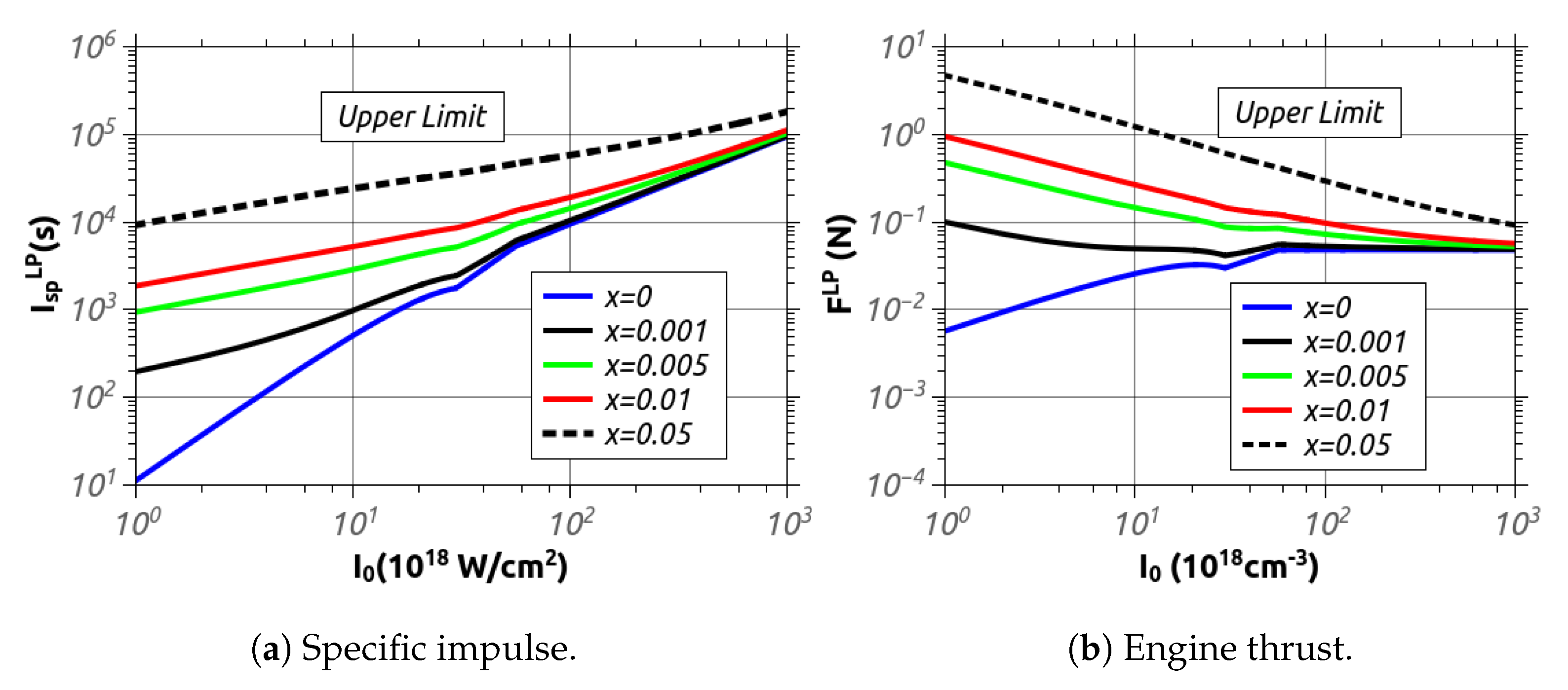
The LAPPS has been analyzed in detail by considering a realistic model including the acceleration of ions close to relativistic speed by means of a pure TNSA mechanism, besides an additional amount of particles accelerated to non–relativistic speed during the laser ablation process. The relative weight of these components determines the figures of merit of the LAPSS engine. An analytical description of LAPPS specific impulse and thrust has been obtained as a function of typical laser–plasma interaction parameters. We find that better performances in terms of I s p are reached for high laser intensities using a thin low atomic number target. For intensities close to I 0 10 21 W / cm 2 , a specific impulse I s p L P 10 5 s can be achieved, with a negligible dependence on secondary acceleration mechanisms. These results suggest that LAPPS is potentially capable of an impressive specific impulse compared to other advanced electric-propulsion schemes. On the other side, the realization of an ideal thrust-mass ratio of 1 N for each tonne is much more challenging as it roughly requires a laser pulse with an energy of ε L 10 3 J and a repetition rate of ν L 1 kHz for a spacecraft of a total mass of few tonnes, which must include a reactor with a thermal power of P R 20 MW. Moreover, the increase of the thrust implies a drastic reduction of the specific impulse down to values comparable to other advanced schemes. In short, optimized thrusts are obtained when a large amount of mass is accelerated at low velocities rather than when a few particles are brought close to relativistic speed, i.e., when the ion acceleration due to laser ablation becomes dominant with respect to the TNSA scheme. Nevertheless, unlike other closed–cycle electric propulsion, the thrust can be continuously adjusted by varying the laser intensity (e.g., by tuning the relative position of the target with respect to the focal spot) to produce a local increasing of the thrust only when required and thus preserving the possibility of deep space traveling using an ultra–high specific impulse.
Realistically, although the TNSA mechanism is widely explored and well–known, the comprehension of secondary accelerating mechanisms is crucial in LAPPS to correctly characterize its performance, especially in the low intensity limit. For these reasons, dedicated experimental measurements are required in order to fix the free parameters of the theory.

Author Contributions

Conceptualization, D.P.; methodology, D.P.; validation, D.P. and G.C.; formal analysis, D.P. and G.C.; writing—original draft preparation, D.P. and G.C.; writing—review and editing, D.P. and G.C.; All authors have read and agreed to the published version of the manuscript.

Funding

This research received no external funding.

Conflicts of Interest

The authors declare no conflict of interest.

Nomenclature

cSpeed of light in vacuum
u μ Four-velocity
uScalar rocket velocity
γ Relativistic factor
θ Rapidity
σ Proper speed
v r Propellant relative velocity
M i Initial rocket mass
MInstantaneous rocket mass
Δ M Consumed fuel
d τ Infinitesimal proper time
a μ Four-acceleration
FRocket thrust
I s p Specific impulse
T i Firing time
( ϵ , η , δ ) Walter’s parameters
v r m Propellant relative speed of massive particles
v r * Effective propellant speed
I s p L Specific impulse of a photon (laser) rocket
η L Laser energy conversion efficiency (Walter’s parameter)
η L P Laser–plasma propulsion energy conversion efficiency (Walter’s parameter)
η I Laser–plasma interaction efficiency
P R Thermal power generated by nuclear reactor
E R Thermal energy generated by nuclear reactor for a single shot
I s p m a x Maximum theoretical specific impulse of a laser–plasma thruster
F L P Laser–plasma propulsion thrust
F L Laser propulsion thrust
AFraction of TNSA particles
τ L Laser pulse duration
τ a c c Ions acceleration time
ε L Laser pulse energy
w 0 Laser waist
g 0 Gravitational acceleration measured on Earth level
φ Angular divergence of TNSA particles
φ Angular divergence of non-TNSA particles
v r I t n s a Averaged relative velocity of TNSA particles
v r A l l Averaged relative velocity of non-TNSA particles
m I Averaged ion mass (TNSA particles)
χ Normalized relative velocity of non-TNSA accelerated particles

References

  1. Sanger, E. Zur Theorie der Photonenraketen. In Probleme der Weltraumforschung Biel-Bienne; 1955; p. 32. Available online: https://in.booksc.eu/book/6048371/855a4c (accessed on 25 October 2021).
  2. Marx, G. Interstellar Vehicle Propelled by Terrestrial laser Beam. Nature 1966, 211, 22–23. [Google Scholar] [CrossRef]
  3. Mockel, W.E. Propulsion by Impinging Laser Beams. J. Spacecr. Rocket. 1972, 9, 942–944. [Google Scholar] [CrossRef]
  4. Kantrowitz, A. The Powerful Laser. Astronaut. Aeronaut. 1971, 9, 34–35. [Google Scholar]
  5. Mockel, W.E. Comparison of Advanced Propulsion Concepts for Deep Space Exploration. J. Spacecr. Rocket. 1972, 9, 863–868. [Google Scholar] [CrossRef] [Green Version]
  6. Phipps, C.; Birkan, M.; Bohn, W.; Eckel, H.A.; Horisawa, H.; Lippert, T.; Michaelis, M.; Rezunkov, Y.; Sasoh, A.; Sinko, J.; et al. Review: Laser-Ablation Propulsion. J. Propul. Power 2010, 26. [Google Scholar] [CrossRef]
  7. Kulkarni, N.; Lubin, P.; Zhang, Q. Relativistic Spacecraft Propelled by Directed Energy. Astron. J. 2018, 155, 155. [Google Scholar] [CrossRef] [Green Version]
  8. Clark, E.L.; Krushelnick, K.; Davies, J.R.; Zepf, M.; Tatarakis, M.; Beg, F.N.; Machacek, A.; Norreys, P.A.; Santala, M.I.K.; Dangor, A.E.; et al. Measurements of Energetic Proton Transport through Magnetized Plasma from Intense Laser Interactions with Solids. Phys. Rev. Lett. 2000, 84, 670–673. [Google Scholar] [CrossRef] [PubMed]
  9. Maksimchuk, A.; Gu, S.; Flippo, K.; Umstadter, D.; Bychenkov, V.Y. Forward Ion Acceleration in Thin Films Driven by a High-Intensity Laser. Phys. Rev. Lett. 2000, 84, 4108–4111. [Google Scholar] [CrossRef] [Green Version]
  10. Snavely, R.A.; Key, M.H.; Hatchett, S.P.; Cowan, T.E.; Roth, M.; Phillips, T.W.; Stoyer, M.A.; Henry, E.A.; Sangster, T.C.; Campbell, E.M.; et al. Intense High-Energy Proton Beams from Petawatt-Laser Irradiation of Solids. Phys. Rev. Lett. 2000, 85, 2945–2948. [Google Scholar] [CrossRef]
  11. Levchenko, I.; Xu, S.; Mazouffre, S.; Lev, D.; Pedrini, D.; Goebel, D.; Garrigues, L.; Taccogna, F.; Bazaka, K. Perspectives, frontiers, and new horizons for plasma-based space electric propulsion. Phys. Plasmas 2020, 27, 020601. [Google Scholar] [CrossRef] [Green Version]
  12. Horisawa, H.; Kimura, I. Characterization of novel laser particle accelerators for space propulsion. In Proceedings of the 36th AIAA/ASME/SAE/ASEE Joint Propulsion Conference and Exhibit, Las Vegas, NV, USA, 24–28 July 2000; pp. 2000–3487. [Google Scholar]
  13. Kammash, T.; Flippo, K.; Umstadter, D. Laser Accelerated Plasma Propulsion System (LAPPS). In Proceedings of the 37th Joint Propulsion Conference and Exhibit, AIAA Paper, Salt Lake City, UT, USA, 8–11 July 2001; pp. 2001–3810. [Google Scholar]
  14. Horisawa, H. Relativistic Laser Plasma Acceleration for Very-High-Specific-Impulse Space Propulsion Applications. J. Space Technol. Sci. 2006, 22, 2_11–2_19. [Google Scholar]
  15. Bae, Y.K. Prospective of Photon Propulsion for Interstellar Flight. Phys. Procedia 2012, 38, 253–279. [Google Scholar] [CrossRef] [Green Version]
  16. Vulpetti, G. Maximum terminal velocity of relativistic rocket. Acta Astronaut. 1985, 12, 81–90. [Google Scholar] [CrossRef]
  17. Kammash, T. A Nuclear-Powered Laser-Accelerated Plasma Propulsion System. AIP Conf. Proc. 2003, 654, 547. [Google Scholar]
  18. Levchenko, I.; Bazaka, K.; Mazouffre, S.; Xu, S. Prospects and physical mechanisms for photonic space propulsion. Nat. Photon 2018, 12, 649–657. [Google Scholar] [CrossRef]
  19. 2020 NASA Technology Taxonomy. Available online: https://www.nasa.gov/sites/default/files/atoms/files/2020_nasa_technology_taxonomy_lowres.pdf (accessed on 25 October 2021).
  20. Macchi, A.; Borghesi, M.; Passoni, M. Ion acceleration by superintense laser–plasma interaction. Rev. Mod. Phys. 2013, 85, 751–793. [Google Scholar] [CrossRef] [Green Version]
  21. Faure, J.; Gustas, D.; Guénot, D.; Vernier, A.; Böhle, F.; Ouillé, M.; Haessler, S.; Lopez-Martens, R.; Lifschitz, A. A review of recent progress on laser–plasma acceleration at kHz repetition rate. Plasma Phys. Control. Fusion 2018, 61, 014012. [Google Scholar] [CrossRef]
  22. Fuchs, J.; Antici, P.; d’Humières, E.; Lefebvre, E.; Borghesi, M.; Brambrink, E.; Cecchetti, C.A.; Kaluza, M.; Malka, V.; Audebert, P.; et al. Laser-driven proton scaling laws and new paths towards energy increase. Nat. Phys. 2006, 2, 48–54. [Google Scholar] [CrossRef]
  23. Wilks, S.C.; Kruer, W.L. Absorption of Ultrashort, Ultra-Intense Laser Light by Solids and Overdense Plasmas. IEEE J. Quantum Electron. 1997, 33, 1954–1968. [Google Scholar] [CrossRef]
  24. Green, J.S.; Ovchinnikov, V.M.; Evans, R.G.; Akli, K.U.; Azechi, H.; Beg, F.N.; Norreys, P.A. Effect of Laser Intensity on Fast-Electron-Beam Divergence in Solid-Density Plasmas. Phys. Rev. Lett. 2008, 100, 15003. [Google Scholar] [CrossRef] [Green Version]
  25. Daido, H.; Nishiuchi, M.; Pirozhkov, A.S. Review of laser-driven ion sources and their applications. Rep. Prog. Phys. 2012, 75, 056401. [Google Scholar] [CrossRef] [PubMed]
  26. Cristoforetti, G.; Baffigi, F.; Brandi, F.; D’Arrigo, G.; Fazzi, A.; Fulgentini, L.; Giove, D.; Koester, P.; Labate, L.; Gizzi, L.A. Laser-driven proton acceleration via excitation of surface plasmon polaritons into TiO2 nanotube array targets. Plasma Phys. Control. Fusion 2020, 62, 114001. [Google Scholar] [CrossRef]
  27. Gizzi, L.A.; Boella, E.; Labate, L.; Baffigi, F.; Bilbao, P.J.; Brandi, F.; Cristoforetti, G.; Fazzi, A.; Fulgentini, L.; Tomassini, P.; et al. Enhanced laser-driven proton acceleration via improved fast electron heating in a controlled pre-plasma. Sci. Rep. 2021, 11, 13728. [Google Scholar] [CrossRef]
  28. Tsiolkovsky, K.E. Reactive Flying Machines; Izdatel’stvo Akademii Nauk SSSR: Moscow, Russia, 1954. [Google Scholar]
  29. Forward, R.L. A Transparent Derivation of the Relativistic Rocket Equation. In Proceedings of the 31st AIAA/ASME/SAE/ASEE 95-3060 Joint Propulsion Conference and Exhibit, San Diego, CA, USA, 10–12 July 1995. [Google Scholar]
  30. Walter, U. Relativistic rocket and space flight. Acta Astronaut. 2006, 59, 453–461. [Google Scholar] [CrossRef]
  31. Westmorelend, S. A note on relativistic rocketry. Acta Astronaut. 2010, 67, 1248–1251. [Google Scholar] [CrossRef] [Green Version]
  32. Myrabo, L.N. MHD Propulsion by Absorption of Laser Radiation. J. Spacecr. Rocket. 1976, 13, 466–472. [Google Scholar] [CrossRef]
  33. Esarey, E.; Schroeder, C.B.; Leemans, W.P. Physics of laser-driven plasma-based electron accelerators. Rev. Mod. Phys. 2009, 81, 1229. [Google Scholar] [CrossRef]
  34. Gizzi, L.A.; Koester, P.; Labate, L.; Mathieu, F.; Mazzotta, Z.; Toci, G.; Vannini, M. A viable laser driver for a user plasma accelerator. Nucl. Inst. Methods Phys. Res. A 2018, 909, 58. [Google Scholar] [CrossRef]
  35. Cristoforetti, G.; Tognoni, E.; Gizzi, L.A. Thermodynamic equilibrium states in laser-induced plasmas: From the general case to laser-induced breakdown spectroscopy plasmas. Spectrochim. Acta Part B 2013, 90, 1–22. [Google Scholar] [CrossRef]
  36. Fuchs, J.; Sentoku, Y.; d’Humières, E.; Cowan, T.E.; Cobble, J.; Audebert, P.; Brambrink, E.; Blazevic, A.; Campbell, E.M.; Pépin, H.; et al. Comparative spectra and efficiencies of ions laser-accelerated forward from the front and rear surfaces of thin solid foils. Phys. Plasmas 2007, 14, 053105. [Google Scholar] [CrossRef]
  37. Kaufman, H.R. Technology of closed-drift thrusters. AIAA J. 1985, 23, 78. [Google Scholar] [CrossRef]
  38. Goebel, D.M.; Katz, I. Fundamentals of Electric Propulsion: Ion and Hall Thrusters; JPL Space Science and Technology Series; Wiley: Hoboken, NJ, USA, 2008. [Google Scholar]
  39. Kammash, T. Ultrafast-Laser Driven Plasma for Space Propulsion. In Proceedings of the AIAA Paper 2002–4090, Indianapolis, Indiana, 7–10 July 2002. [Google Scholar]
Figure 1. A schematic image of a relativistic rocket system. The relativistic propellant, of infinitesimal mass d m , is expelled to produce the rocket motion. In case of massless propellant, d m v μ is the photons four–momentum.
Applsci 11 10154 g001
Figure 2. Energy scheme calculated in the rocket space frame. The total infinitesimal mass d M lost by the rocket is related to the rest mass of the accelerated particles, their energy and the energy of the massless expelled particles. Energy that is not used to accelerate the rocket is considered wasted energy.
Applsci 11 10154 g002
Figure 3. Basic scheme of the Laser-Accelerated Plasma-Propulsion System (LAPPS). The laser system is represented by the red box. LAPPS is a closed cycle engine.
Applsci 11 10154 g003
Figure 4. The plots consider the intensity range I 0 = 10 18 10 21 W / cm 2 and a laser wavelength λ L = 0.8 μ m , typical of a Ti:Sa laser system. The discontinuity in the subplot (a) corresponds to the saturation of conversion efficiency Ω ( I 0 ) = 0.5 . In subplot (b), low Z metals and typical constituent of organic polymers are considered. Except for the carbon, only first ionization is considered in order to present the lower velocity limit of each species.
Applsci 11 10154 g004
Figure 5. On the left, the fraction A of the TNSA accelerated particle as a function of laser intensity. Uniformly ionized C + and C 6 + targets, with thickness d = 5 μ m and density ρ = 1 g / cm 3 , irradiated by a laser pulse of duration τ L = 100 fs , have been considered. On the right, the scheme of a laser–solid target interaction. The propellant includes a variety of contributions including radiation.
Applsci 11 10154 g005
Figure 6. Specific impulse and engine thrust calculated for a C 6 + target as a function of laser intensity. Parameters are fixed by d = 5 μ m , ρ = 1 g / cm 3 and τ L = 100 fs . The considered angular spread are φ = 30 ° and φ = 60 °, while 1 ϵ = 90 % . The function χ 0.05 is used as a fixed parameter. In subplot (b) the engine thrust is calculated at fixed pulse energy of ε L = 5 × 10 3 J with a laser repetition rate of ν L = 1 kHz.
Applsci 11 10154 g006
Figure 7. Engine thrust as a function of laser intensity at fixed pulse energy ε L = 10 3 J. A uniformly ionized C 6 + target with a density of ρ = 1 g / cm 3 has been considered. Different target thickness and pulse duration have been analyzed. The laser repetition rate is fixed by ν L = 1 kHz.
Applsci 11 10154 g007
Figure 8. Thrust as a function of the specific impulse at fixed pulse energy ε L = 10 3 J. A uniformly ionized C 6 + target with a density of ρ = 1 g / cm 3 has been considered. The laser repetition rate is fixed by ν L = 1 kHz. In case of photon rocket, the thrust is given by F L = ν L ε L / c .
Applsci 11 10154 g008
Publisher’s Note: MDPI stays neutral with regard to jurisdictional claims in published maps and institutional affiliations.

