Article

Autonomous Driving Robot That Drives and Returns along a Planned Route in Underground Mines by Recognizing Road Signs

Department of Energy Resources Engineering, Pukyong National University, Busan 48513, Korea
*
Author to whom correspondence should be addressed.
Appl. Sci. 2021, 11(21), 10235; https://doi.org/10.3390/app112110235
Submission received: 12 August 2021 / Revised: 21 October 2021 / Accepted: 27 October 2021 / Published: 1 November 2021

Abstract

:
In this study, an autonomous driving robot that drives and returns along a planned route in an underground mine tunnel was developed using a machine-vision-based road sign recognition algorithm. The robot was designed to recognize road signs at the intersection of a tunnel using a geometric matching algorithm of machine vision, and the autonomous driving mode was switched according to the shape of the road sign to drive the robot according to the planned route. The autonomous driving mode recognized the shape of the tunnel using the distance data from the LiDAR sensor; it was designed to drive while maintaining a fixed distance from the centerline or one wall of the tunnel. A machine-vision-based road sign recognition system and an autonomous driving robot for underground mines were used in a field experiment. The results reveal that all road signs were accurately recognized, and the average matching score was 979.14 out of 1000, confirming stable driving along the planned route.

1. Introduction

Autonomous driving technology enables vehicles to automatically drive to a desired point by recognizing and judging the driving environment. Recently, autonomous driving technology has been applied to mobile robots and is being used in fields such as manufacturing [1], logistics [2], and national defense [3]. Many studies [4,5,6,7,8,9,10,11,12] have been conducted to implement high-level autonomous driving technology in these fields. For example, Datta et al. [13] tested various tasks in a manufacturing environment using autonomous mobile robots equipped with wheel encoders, cameras, light detection and ranging (LiDAR), and robot arms. Wang and Du [14] developed an autonomous driving robot for logistics using an infrared sensor, encoder, global positioning system (GPS), ultrasonic sensor, navigation, path planning, and information fusion functions. Park et al. [15] developed a military autonomous driving robot equipped with a laser scanner, GPS, and camera.
In the mining industry, several studies of autonomous driving technology have been conducted in underground mining environments using autonomous robots [16,17,18,19,20,21,22,23,24,25,26]. Baker et al. [27] developed “groundhog”, an autonomous driving robot that can be used even in underground mines having poor road conditions. The autonomous driving robot was able to recognize the surrounding environment through the fusion of multiple sensors, perform tasks such as tunnel mapping, and return to the starting point. Field driving tests were performed in an abandoned mine environment using the developed autonomous driving robot, and stable driving performance was confirmed. Bakambu [28] used an autonomous robot to estimate real-time location in an underground mining environment, performed 2D and 3D tunnel mapping work, and evaluated its accuracy.
Recently, studies have been conducted on the use of autonomous robots with camera sensors for underground mining [29,30]. Zhao et al. [31] developed an autonomous driving robot to perform initial exploration work in case of a human accident in an underground coal mine. In addition to being capable of autonomous driving, the developed robot can be remote controlled, and is equipped with a toxic gas detection sensor, camera sensor, and long-distance wireless communication router; furthermore, the operator can check the driving environment in real time using a camera. Jing et al. [32] performed 3D tunnel mapping for an underground mine tunnel using mobile robots and a depth camera that can recognize 3D views. Zeng et al. [33] developed a real-time localization system in an underground mine using an autonomous driving loader for underground mining and a camera sensor. The developed localization system was able to perform accurate localization by integrating image processing technology and simultaneous localization and mapping.
As aforementioned, most previous studies using autonomous robots in underground mines involved autonomous driving along only certain straight paths in underground mine tunnels. However, in a real underground mining environment, autonomous driving in a straight tunnel section as well as path planning technology to drive, for example, in a planned direction on a two-way road or returning after arriving at a turning point, are required. In addition, in underground mines, the shape of the tunnel is frequently changed by the blasting of the tunnel for mining minerals, making it difficult to effectively utilize the route planning technology using the global map surveyed in advance. Therefore, to improve the utilization of autonomous robots for underground mining, technologies for efficiently recognizing road signs using a camera sensor-based vision system and driving along a planned route in an underground mine without a global map should be developed.
The purpose of this study was to realize the autonomous driving and returning of a robot along a planned route in underground mine tunnels using a machine-vision-based road sign recognition algorithm. While driving, the autonomous driving robot recognizes the shape of the underground mine using a LiDAR sensor and drives along the centerline of the road. After recognizing the road sign, it switches to the left or right wall-following driving mode. In this paper, the system configuration of autonomous driving robots and the road sign recognition algorithm are explained, and the results of field experiments in underground mines are presented.

2. Materials and Methods

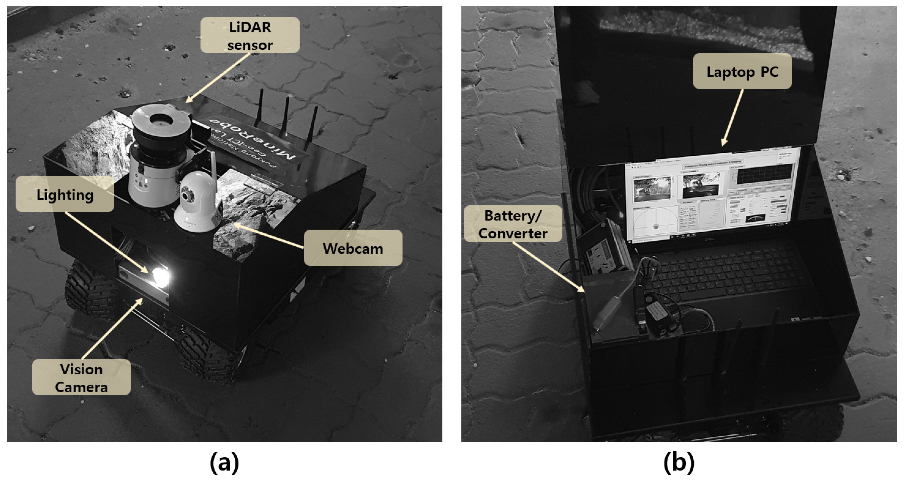
2.1. Autonomous Driving Robot

Table 1 provides the details of the equipment of the autonomous driving robot system developed in this study. Th autonomous driving robot consists of a controller, mobile robot, and sensors. In this study, a laptop PC with a Windows 10 (Microsoft Corporation, Redmond, WA, USA) operating system was used as the main controller, and an ERP-42 robot equipped with four-wheel drive and four-wheel steering was used as the mobile robot. A vision camera, LiDAR sensor, inertial measurement unit (IMU) sensor, and wheel encoder sensor were used to perform pose estimation, localization, and object detection. The vision camera used was the Bumblebee XB3, a stereo camera, but only RGB images were used because road signs had to be recognized. The IMU sensor fuses the magnetometer, acceleration, and gyroscope sensor using a Kalman filter to output the 3-axis Euler angle for the robot’s pose [26].
Figure 1 shows the interior and exterior of the autonomous driving robot developed in this study. A LiDAR sensor, webcam, and vision camera were installed in the front side the robot. A LiDAR sensor was used to recognize the shape of the underground mine tunnel, and the webcam was designed to transmit the webcam display to the remote laptop. In addition, a vision camera was used to recognize road signs. A battery and converter were placed to supply power to the robot and the sensors. A protective case was used to safeguard the internal equipment from external physical shocks and water leakage.

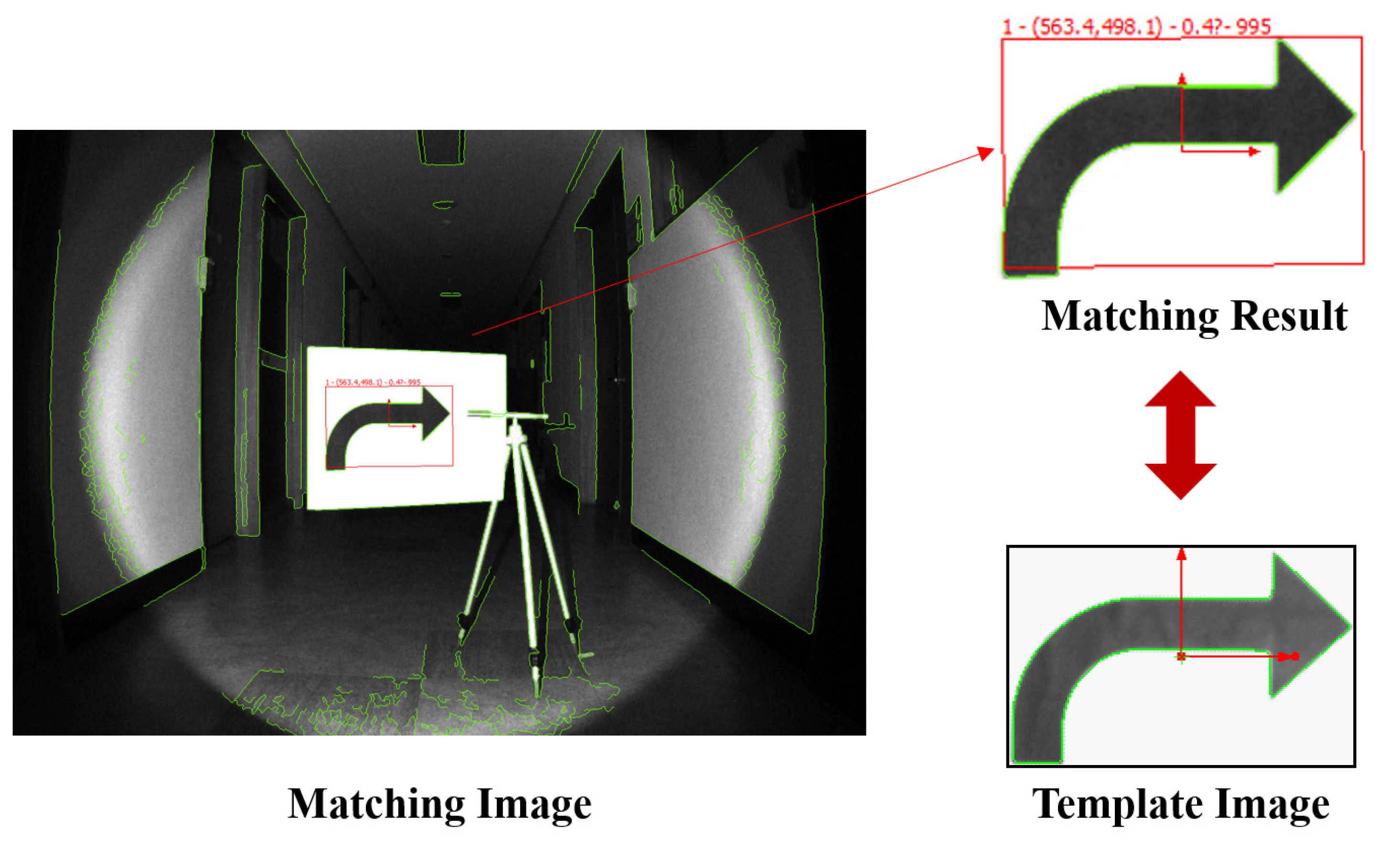
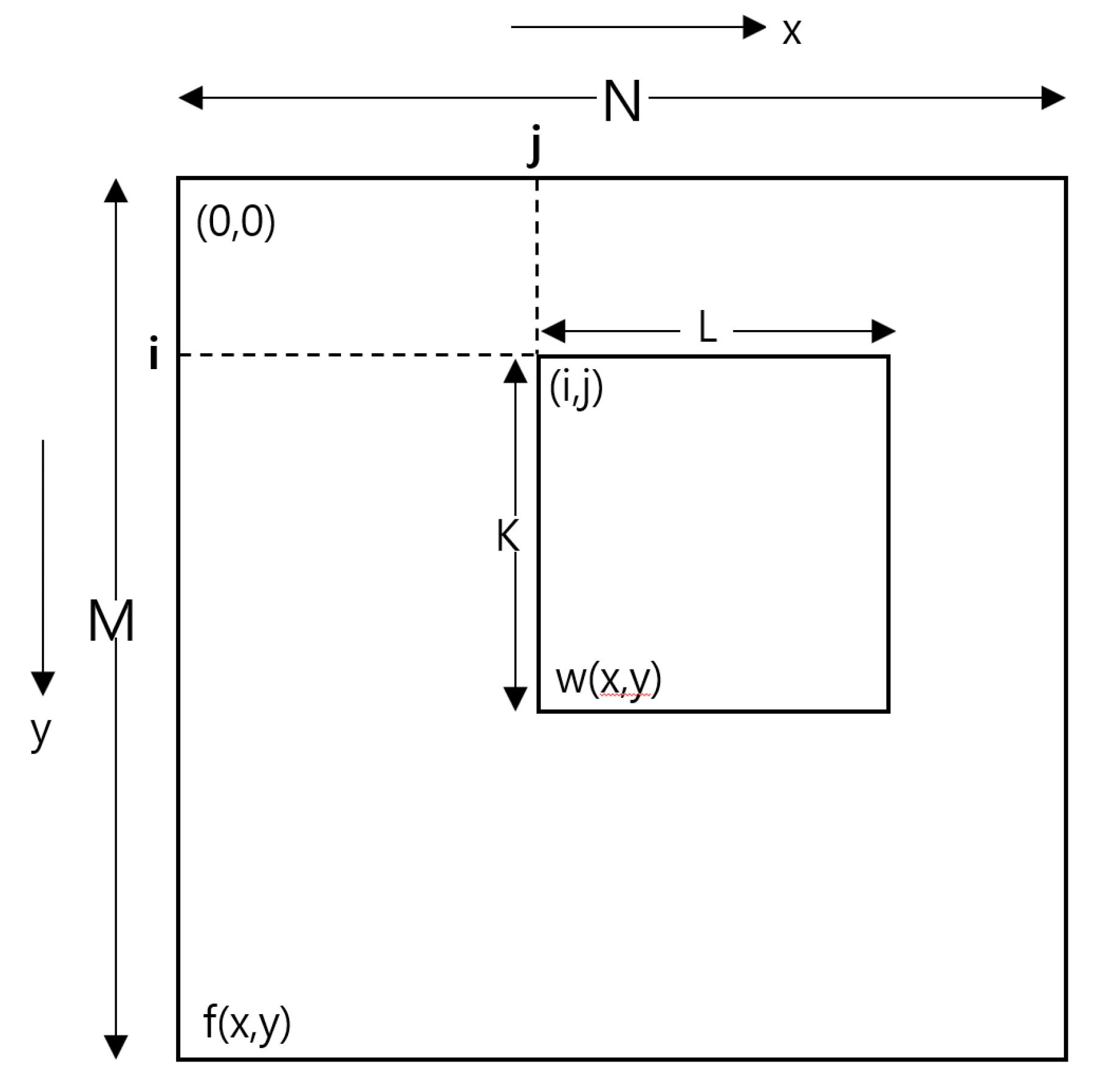
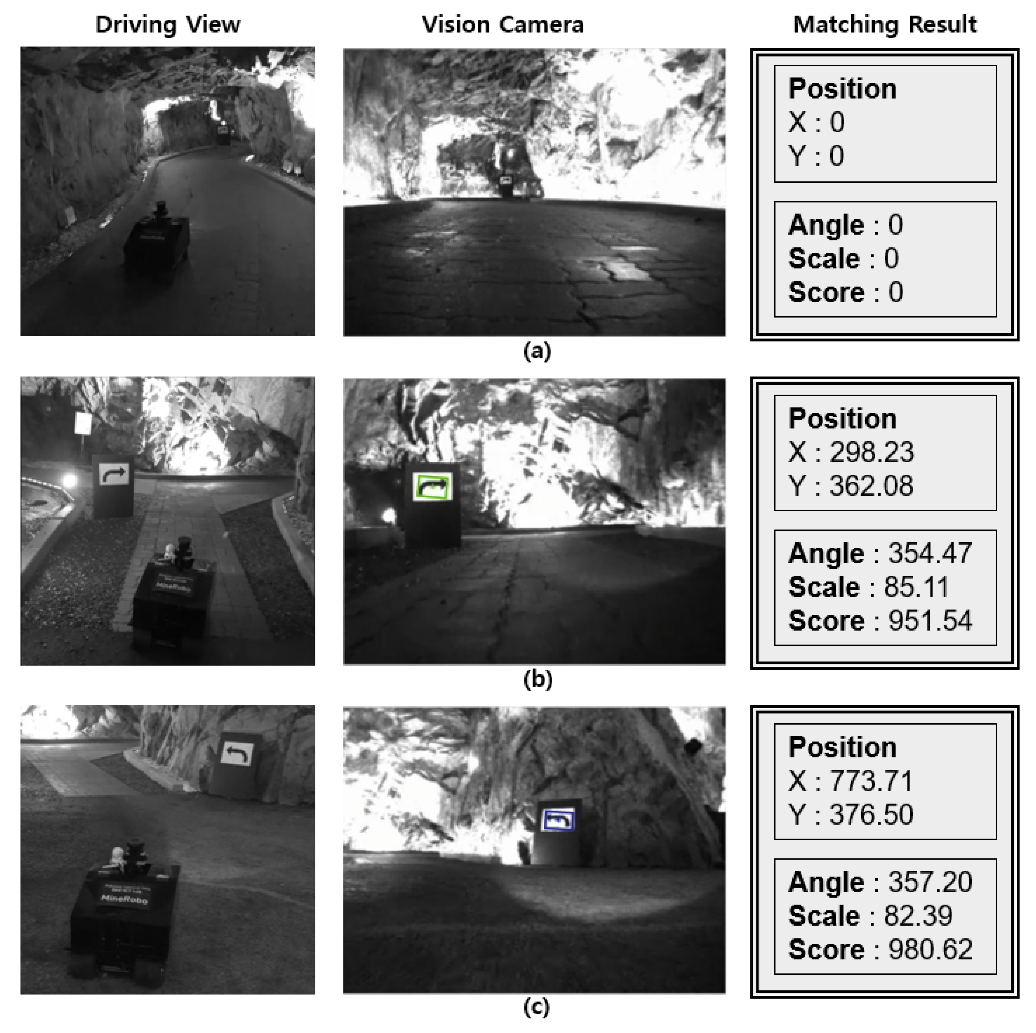
2.2. Machine Vision Algorithm

In this study, a machine vision algorithm was used to recognize road signs in underground mines. In the case of general roads, an object recognition technology based on artificial intelligence using a large amount of learning data should be used to recognize a wide variety of road signs. In contrast, in the case of underground mines, it is sufficient to recognize only the right and left road signs at intersections because the driving route is limited to the excavated tunnel. Therefore, in this study, we used a geometric matching algorithm, which is a machine vision technology that uses a single image as learning data to recognize road signs without the use of several computational resources.
Geometric matching is a technology that detects the boundary line of an object using an edge detection algorithm, compares it with the shape of a template image, and matches it. Geometric matching algorithms can be used efficiently when the distinction between the object and the background is clear; however, the efficiency is low when the boundary of the object is not clear or when matching only a part of the object. Geometry matching shows high performance even in the presence of lighting changes, blurring, and noise. It can be efficiently performed based on geometrical shape changes, such as the movement, rotation, and scale change of an object on a screen. Geometric matching can be classified into commonly used edge-based geometric matching techniques and feature-based geometric matching techniques for matching circular, square, and linear template images. The geometric matching algorithm consists of the following steps: learning (curve extraction and feature extraction) and matching (feature correspondence matching, template model matching, and match refinement). Figure 2 shows the template image and matching result of geometric matching. At the top of the matching result image, the matching image number, the center pixel coordinates of the matched image, and the matching score are displayed.
This method employs normalized gray values and implements more accurate matching when there is a dense texture. When the size of the template image is K × L and the size of the target image is M × N, the cross correlation at (i, j) is calculated using Equation (1). Figure 3 shows the correlation between the template image and the target image when performing pattern matching [34].
C ( i , j ) = x = 0 L 1 y = 0 K 1 ( w ( x , y ) w ¯ ) ( f ( x + i , y + j ) f ( i , j ) ¯ ) x = 0 L 1 y = 0 K 1 ( w ( x , y ) w ¯ ) 2 x = 0 L 1 y = 0 K 1 ( f ( x + i , y + j ) f ( i ,   j ) ) 2
where i = 0, 1, 2, …, M−1 and j = 0, 1, 2, .... The correlation is calculated through the C(i, j) value at the highest point among the values up to N − 1.
The accuracy of the matching algorithm is calculated using Equation (2) [35]. In this study, National Instruments Vision Development Module, Vision Acquisition Software, Vision Builder for Automated Inspection, Vision Assistant, and LabVIEW were used to implement each matching algorithm [36].
Match   Score = Matched   Pixels Total   Pixels   in   ROI × 1000
The match score indicates the matching accuracy score. It is output as a number between 0 and 1000, and the closer it is to 1000, the higher the accuracy. The region of interest (ROI) represents the area where matching is performed; in this study, it represented the entire area captured by the camera.

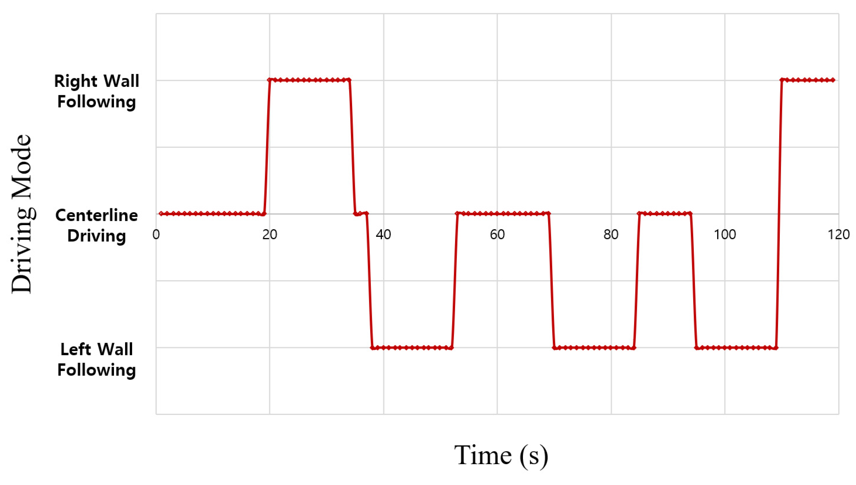
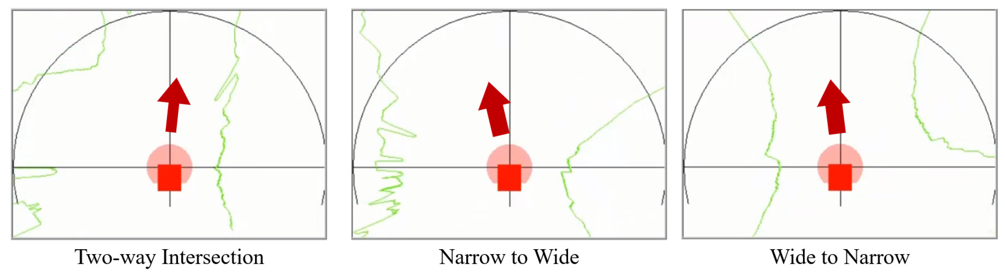
2.3. Autonomous Driving and Wall following Algorithm

In this study, we controlled the steering of an autonomous driving robot through the distance difference between the left and right shaft walls measured through the LiDAR sensors and the road signs detected by the vision camera. The autonomous driving robot captured the RGB image from the vision camera, converted it into a grayscale image, and checked the presence of road signs in real time using the road sign recognition algorithm. If the road sign was not detected, the distance to the left and right walls was measured using an autonomous driving algorithm, and the robot drove along the centerline of the road [22]. If the road sign was detected, the distance to the sign was calculated by comparing the scale of the sign on the screen with the size of the actual road sign. The road sign used in this study was 40 cm wide and 30 cm long. The type of road sign was recognized when it was measured to be closer than the threshold distance. The distance was measured in the left or right direction according to the type of recognized sign, and the vehicle traveled along one wall at a certain distance. In this study, considering the speed of the robot and the width of the underground mine tunnel, the robot was designed to detect when the road sign was less than 5 m away, and it drove approximately 2 m away from the wall. Figure 4 shows the processing diagram of the road sign recognition and autonomous driving algorithms.
Equations (3)–(7) show the relationship between the distance differences (X input) measured from the LiDAR sensor and the steering angle (Y output) for the autonomous driving algorithm developed in this study. Here, X represents the value obtained by subtracting the distance to the left wall from the distance to the right wall, and the Y value represents the steering value of the robot. Max. Threshold and Min. Threshold represent the maximum and minimum threshold values at which the steering value changes, respectively. That is, the Max. steering and Min. steering mean the maximum values that can be moved in the left and right directions, respectively; the Max. Threshold and Min. Threshold mean the threshold values at which the maximum and minimum steering values start, respectively. Max. Steering and Min. Steering are the steering values for when the robot rotates, with a value between −100 and 100, with the left side representing (−) and the right side representing (+). While the autonomous driving algorithm uses the distance difference between the left and right walls, the wall-following algorithm controls steering through the distance difference from one side wall [23]. That is, the autonomous driving mode or the wall tracking mode is switched according to the direction indicated by the road mark, and the left and right steering are automatically controlled.
X < Max . Threshold ,   Y = Max . Steering
Max . Threshold X < Min . Threshold ,   Y = Max . SteeringValue ( X Min . Threshold ) 2 ( Min . Threshold Max . Treshold ) 2
Min . Threshold X Min . Threshold ,   Y = 0
Min . Threshold < X Max . Threshold ,   Y = Max . SteeringValue ( X Min . Threshold ) 2 ( Max . Threshold Min . Threshold ) 2
X > Max . Threshold ,   Y = Max . Steering

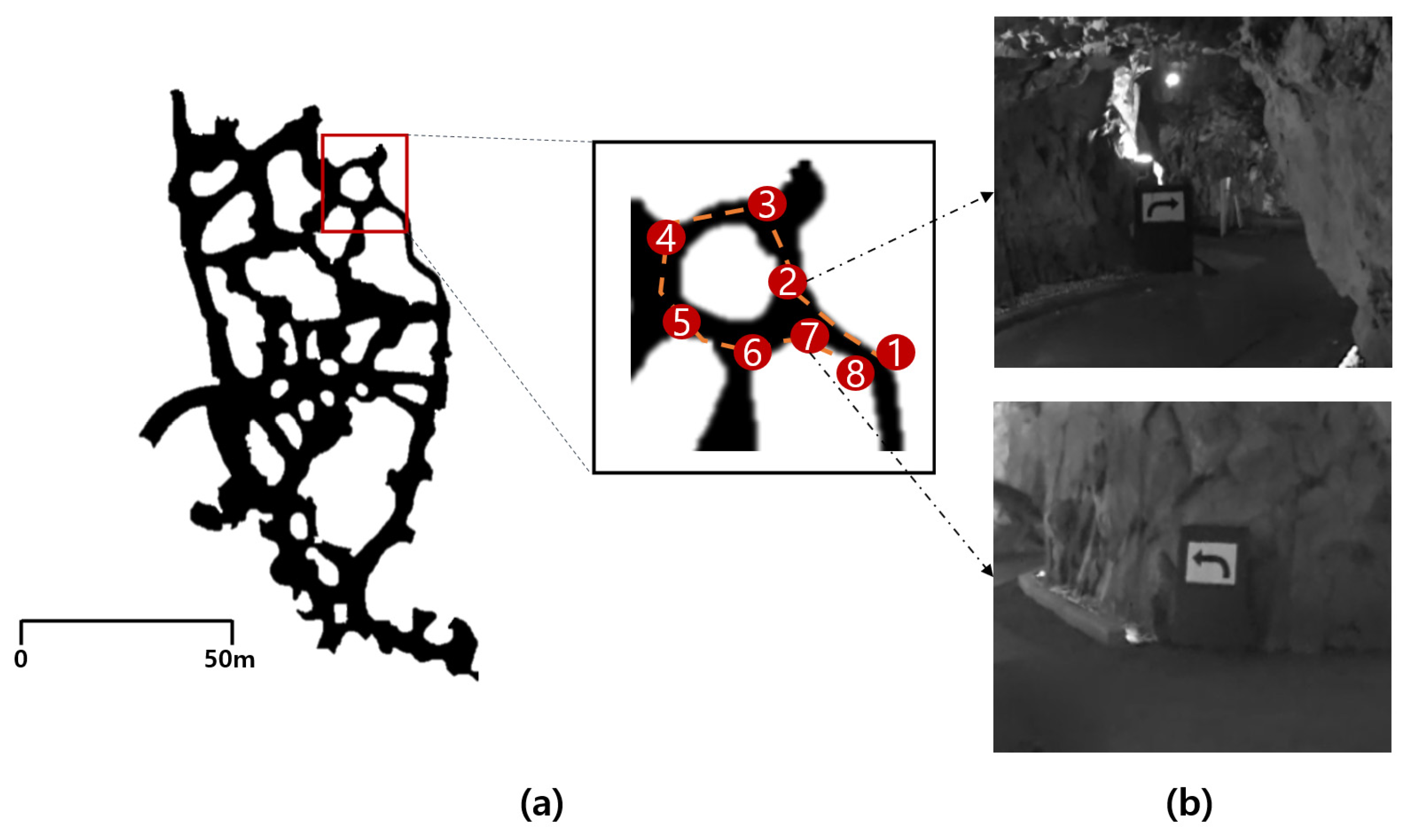
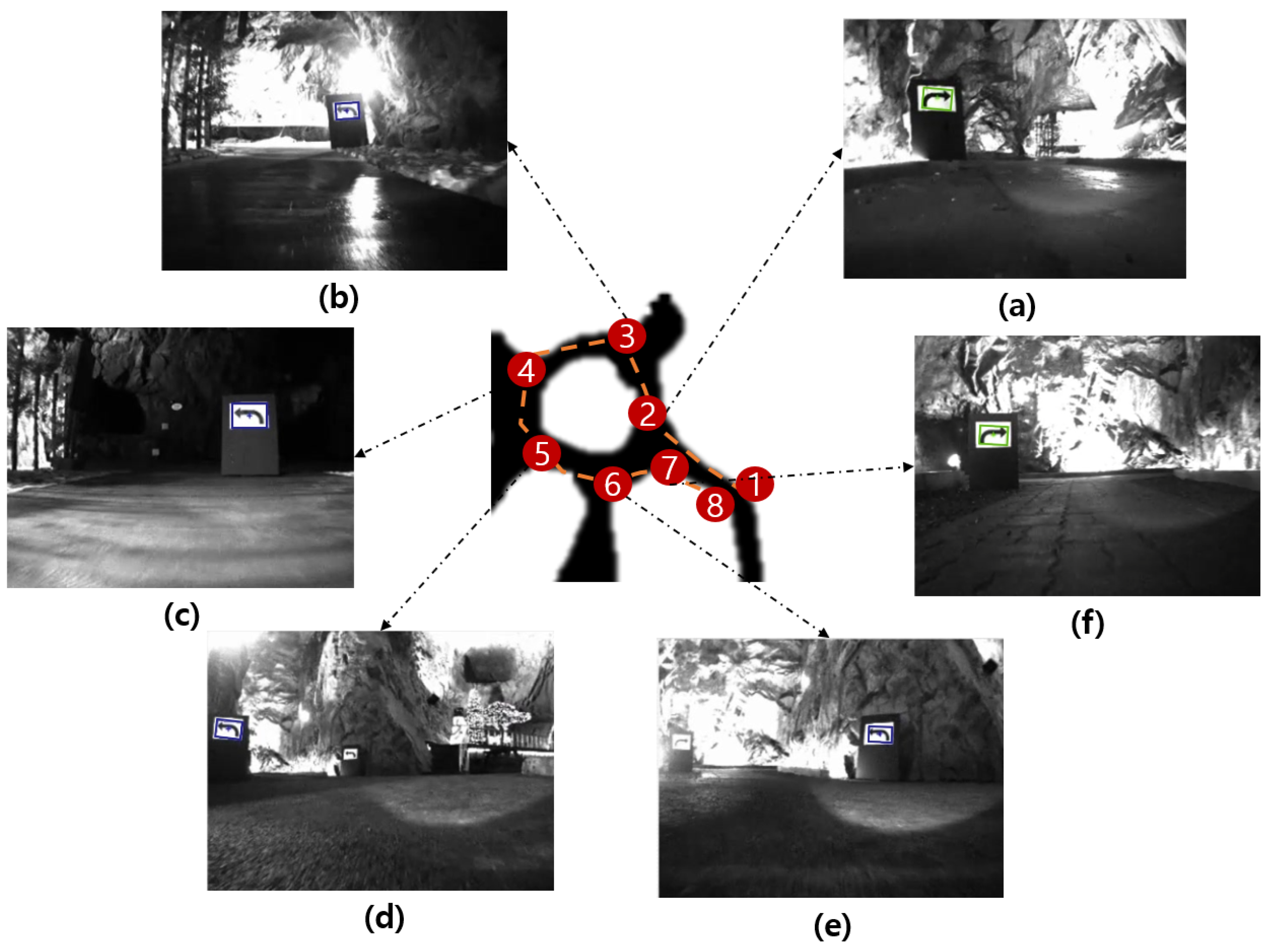
2.4. Field Experiment

Field experiments were conducted in an abandoned underground amethyst mine located in Korea (35°32′43″ N, 129°5′37″ E). Specific areas with a length of approximately 60 m and a height of 2.5 m among all the underground mine tunnels were selected as areas for conducting the experiment, as shown in Figure 5. As shown in Figure 5, the driving route was set by starting from Area 1 and returning to Area 8, and a total of six road signs were placed in areas 2, 3, 4, 5, 6, and 7.
In this study, the road sign installed in the underground mine shaft was recognized through the optimal matching algorithm selected from the indoor experiment, and the driving mode was switched to the wall-following algorithm in the left and right directions according to the type of road sign. In addition, when the wall-following mode continued for more than 15 s, it switched to the autonomous driving mode that enables driving along the centerline of the road. During the experiment, the driving path of the robot and the screen of the laptop PC were recorded and analyzed for the driving path, driving state, and recognition accuracy of road signs.

3. Results

Figure 6 shows the autonomous driving robot recognizing road signs in the underground mine, driving straight and taking left and right turns; in addition, the matching results of road signs are shown. In the straight section, we confirmed that the robot drove along the centerline of the tunnel, measuring both the distance to the wall in the left and right directions without recognizing the road sign (Figure 6a). In the left and right turn sections, we confirmed that the robot drove along the left and right walls by recognizing the road sign and switching the autonomous driving mode (Figure 6b,c). In the matching result in Figure 6, it can be seen that the x and y coordinates of the detected road sign were output. In addition, the rotation angle of the mark, the scale for the template image, and the matching score were calculated. The autonomous driving robot drove safely in an underground mine tunnel of approximately 60 m for 128 s without a global map, and we confirmed that, after recognizing road signs, it returned stably while following the left and right walls.
Figure 7 illustrates the process of changing the autonomous driving mode when the autonomous robot drove through the tunnel. While driving through the underground mine experiment area, it drove for 49 s in the centerline autonomous driving mode, 25 s in the right wall-following mode, and 45 s in the left wall-following mode. We confirmed that the robot’s driving mode switched when six road signs were recognized; furthermore, when the wall-following mode lasted for more than 15 s, it switched back to centerline tracking autonomous driving mode.
Figure 8 presents the data of the LiDAR sensor obtained from three road types (two-way intersection, narrow-to-wide section, and wide-to-narrow section) and the robot’s driving direction. At the two-way intersection, after recognizing the road sign in the right direction, the robot drove along the right side at a constant distance. In the narrow-to-wide section where the width of the road widened rapidly, after recognizing the road signs in the left direction, the robot drove along the left side. In addition, in the wide-to-narrow section, after recognizing the sign in the left direction, it was possible for the robot to safely enter the narrow path without colliding with the right wall.
Figure 9 shows the results of recognizing road signs when the robot was driving in an underground mine. The autonomous driving robot recognized all road signs at a total of six points and correctly classified the road signs in the left and right directions. In Figure 9, two road signs were captured together. However, the road signs recognition system calculated the distance by comparing the size of the matched image with the template image and recognized the relatively close road marker first. In addition, we confirmed that the autonomous robot sequentially recognized the road signs in the back. The matching score for a total of six points was calculated as 979.14 points on average, the scale was 80–120%, and the rotation was measured to be ±10° (Table 2).

4. Discussion

4.1. Applications and Expected Effect

An autonomous driving robot was employed in this study for underground mining using the developed road sign recognition algorithm; the robot not only drove in a straight tunnel, but also selected a path to drive at the intersection by recognizing the road signs without a global map. It was feasible to perform multipoint path planning to return to the tunnel entrance. In addition, if path-following technology can be used to drive and return to a desired point in an area that is difficult for humans to access and where the driving route changes frequently, such as in underground mines, the utilization of autonomous robots will be useful in fields such as safe exploration and tunnel surveying.
Even if there is not enough learning image data for road signs due to the environmental characteristics of underground mines, if an image matching algorithm that applies only a single image as training data is used, road signs can be recognized efficiently. In addition, a stable recognition performance can be maintained if the geometric matching algorithm most suitable for an underground mining environment is used.

4.2. Limitations and Future Work

  • Artificial intelligence object recognition: The shape of the entire tunnel changes frequently because of the ongoing excavation work in underground mines, and accordingly, the movement paths of vehicles and workers also change frequently. Hence, road signs at actual underground mine sites are often temporarily marked on the wall. Therefore, the utilization of the road sign recognition system can be expected to further expand if the image of each temporary marker is stored as data and object recognition technology that uses a large number of learning images, such as machine learning and deep learning, is used. In addition, the recognition of static objects, such as workers or transport equipment in the tunnel, as well as stationary road signs, may be performed.
  • Sensor: Because there are no lanes in underground mines, the drivable area is unclear, and because the shape of the tunnel wall is irregular, collisions may occur in unpredictable areas. Therefore, it is suggested to use not only the 2D LiDAR sensor or vision camera in this study, but also a 3D LiDAR that can widely recognize the rear, side, and upper part of the tunnel. In addition, because the intensity of lighting is different for each underground mining site, and the accuracy of matching may be reduced if the lighting is too strong, an illuminance sensor that can recognize the illuminance intensity of the surroundings and reflect it in the lighting system should be additionally utilized.
  • Specificity of the underground mining site: The underground mining site has various sections such as a U-turn area, a three-pronged road, and an area where minerals are loaded, in addition to straight, left, and right turns. Therefore, to consider these environmental characteristics and changes, additional research on autonomous driving algorithms for driving in complex routes should be conducted.
  • Road sign visibility: In an underground mine environment, dust is frequently generated by blasting, and puddles and mud can be caused by stagnant water on the edge of the road. The visibility of the road sign may be limited by these factors, and the robot may not accurately recognize the road sign. Therefore, for a robot to drive along a planned route, elements (dust, mud) that hinder visibility must be periodically removed. In addition, in mines with large shafts, the minimum size to clearly recognize road signs should be considered when driving along the centerline of the road, and the installation location of road signs should be selected so as not to interfere with the robot’s driving route [37].

5. Conclusions

In this study, an autonomous driving robot for underground mines and a road sign recognition system using a machine-vision-based geometric matching algorithm were developed. The developed system was designed to recognize road signs using a vision camera and switch the autonomous driving mode for returning to the planned route while the robot was driving through an underground mine. A field experiment conducted in an underground mine demonstrated a matching score of 979.14 out of 1000. We confirmed that the road signs were accurately recognized at all points, and the robot was driven stably according to the wall tracking algorithm.
In the previous studies for developing autonomous robots utilized in underground mines [22,23,24,25,26], the robots were forced to drive along a simple one-way route. However, this study demonstrated that autonomous robots can drive complex multipoint routes in underground mines while recognizing the road signs using a machine-vision-based algorithm. Therefore, it became possible for autonomous robots to perform missions such as environmental monitoring, 3D tunnel mapping, and accident detection as they navigate complex routes in underground mines. Nevertheless, this study has a limitation in that the driving experiment was conducted on flat and smooth road surfaces. In the future, driving experiments and performance evaluation on rough and unpaved road surfaces should be conducted.
Underground mines present environmental challenges in the application of autonomous driving technology because GPS cannot be used and there are no lanes in such environments. In particular, there is a limitation in that it is difficult to recognize road signs, workers, and transport equipment because of insufficient light. Therefore, to increase the utilization of autonomous driving technology in underground mining environments, it is very important to develop and utilize a vision system that can recognize a wide range of environments. The results of this study are expected to be useful reference materials for autonomous driving technology to be used in underground mines in the future.

Author Contributions

Conceptualization, Y.C.; data curation, Y.C.; funding acquisition, Y.C.; investigation, H.K. and Y.C.; methodology, H.K. and Y.C.; project administration, Y.C.; resources, Y.C.; software, Y.C.; supervision, Y.C.; validation, H.K.; visualization, H.K.; writing—original draft, H.K.; writing—review and editing, Y.C. All authors have read and agreed to the published version of the manuscript.

Funding

This work was supported by a National Research Foundation of Korea (NRF) grant funded by the Korean government (MSIT) (2021R1A2C1011216).

Institutional Review Board Statement

Not applicable.

Informed Consent Statement

Not applicable.

Data Availability Statement

Data sharing not applicable.

Conflicts of Interest

The authors declare no conflict of interest.

References

  1. Bavelos, A.C.; Kousi, N.; Gkournelos, C.; Lotsaris, K.; Aivaliotis, S.; Michalos, G.; Makris, S. Enabling Flexibility in Manufacturing by Integrating Shopfloor and Process Perception for Mobile Robot Workers. Appl. Sci. 2021, 11, 3985. [Google Scholar] [CrossRef]
  2. Kassai, E.T.; Azmat, M.; Kummer, S. Scope of Using Autonomous Trucks and Lorries for Parcel Deliveries in Urban Settings. Logistics 2020, 4, 17. [Google Scholar] [CrossRef]
  3. Reis, J.; Cohen, Y.; Melão, N.; Costa, J.; Jorge, D. High-Tech Defense Industries: Developing Autonomous Intelligent Systems. Appl. Sci. 2021, 11, 4920. [Google Scholar] [CrossRef]
  4. Fox, D.; Burgard, W.; Thrun, S. The dynamic window approach to collision avoidance. IEEE Robot. Autom. Mag. 1997, 4, 23–33. [Google Scholar] [CrossRef] [Green Version]
  5. Adams, M.; Zhang, S.; Xie, L. Particle filter based outdoor robot localization using natural features extracted from laser scanners. In Proceedings of the IEEE International Conference on Robotics and Automation (ICRA ’04), New Orleans, LA, USA, 26 April–1 May 2004; Volume 2, pp. 1493–1498. [Google Scholar]
  6. Thrun, S.; Burgard, W.; Fox, D. Probabilistic Robotics; MIT Press: Cambridge, MA, USA, 2005. [Google Scholar]
  7. Moreno, L.; Armingol, J.M.; Garrido, S.; De La Escalera, A.; Salichs, M.A. A genetic algorithm for mobile robot localization using ultrasonic sensors. J. Intell. Robot. Syst. Theory Appl. 2002, 34, 135–154. [Google Scholar] [CrossRef] [Green Version]
  8. Liu, C.; Zhou, C.; Cao, W.; Li, F.; Jia, P. A Novel Design and Implementation of Autonomous Robotic Car Based on ROS in Indoor Scenario. Robotics 2020, 9, 19. [Google Scholar] [CrossRef] [Green Version]
  9. Boston Dynamics. Available online: https://www.bostondynamics.com/ (accessed on 5 July 2021).
  10. DAIMLER’S PROMETHEUS Project. Available online: https://media.daimler.com/marsMediaSite/en/instance/ko/The-PROMETHEUS-project-launched-in-1986-Pioneering-autonomous-driving.xhtml?oid=13744534 (accessed on 5 July 2021).
  11. Masood, K.; Dauptain, X.; Zoppi, M.; Molfino, R. Hydraulic Pressure-Flow Rate Control of a Pallet Handling Robot for an Autonomous Freight Delivery Vehicle. Electronics 2020, 9, 1370. [Google Scholar] [CrossRef]
  12. Mercorelli, P. Using Fuzzy PD Controllers for Soft Motions in a Car-like Robot. Adv. Sci. Technol. Eng. Syst. J. 2018, 3, 380–390. [Google Scholar] [CrossRef] [Green Version]
  13. Datta, S.; Ray, R.; Banerji, D. Development of autonomous mobile robot with manipulator for manufacturing environment. Int. J. Adv. Manuf. Technol. 2008, 38, 536–542. [Google Scholar] [CrossRef]
  14. Wang, C.; Du, D. Research on logistics autonomous mobile robot system. In Proceedings of the 2016 IEEE International Conference on Mechatronics and Automation, Harbin, China, 7–10 August 2016. [Google Scholar]
  15. Park, Y.; Jee, T.; Kang, S.; Ryu, C.; Ko, J. Implementation of Autonomous Navigation based on the Open Architecture. J. Inst. Electron. Eng. Korea 2007, 44, 34–38. [Google Scholar]
  16. Miller, I.D.; Fernando, C.; Anthony, C.; Shivakumar, S.S.; Lee, E.S.; Jarin-Lipschitz, L.; Akhilesh, B.; Rodrigues, N.; Zhou, A.; Cohen, A.; et al. Mine Tunnel Exploration Using Multiple Quadrupedal Robots. IEEE Rob. Autom. Lett. 2020, 5, 2840–2847. [Google Scholar] [CrossRef] [Green Version]
  17. Berglund, T.; Brodnik, A.; Jonsson, H.; Staffanson, M.; Söderkvist, I. Planning Smooth and Obstacle-Avoiding B-Spline Paths for Autonomous Mining Vehicles. IEEE Trans. Autom. Sci. Eng. 2010, 7, 167–172. [Google Scholar] [CrossRef] [Green Version]
  18. Bakambu, J.N.; Polotski, V. Autonomous system for navigation and surveying in underground mines. J. Field Rob. 2007, 24, 829–847. [Google Scholar] [CrossRef]
  19. Shaffer, G.K.; Stentz, A.; Whittaker, W.L.; Fitzpatrick, K.W. Position Estimator for Underground Mine Equipment. IEEE Trans. Ind. Appl. 1992, 28, 1131–1140. [Google Scholar] [CrossRef]
  20. MobileTronics’s VirtuRail. Available online: https://innovation.strabag.com/en/project/virturail-with-an-autonomous-train-into-the-heart-of-the-tunnel/ (accessed on 5 July 2021).
  21. Günther, F.; Mischo, H.; Lösch, R.; Grehl, S.; Güth, F. Increased safety in deep mining with iot and autonomous robots. In Proceedings of the 39th International Symposium ‘Application of Computers and Operations Research in the MIneral Industry’(APCOM 2019), Wroclaw, Poland, 4–6 June 2019; Mueller, C., Assibey-Bonsu, W., Baafi, E., Dauber, C., Doran, C., Jaszczuk, M.J., Nagovitsyn, O., Eds.; CRC Press: London, UK, 2019; pp. 101–105. [Google Scholar]
  22. Kim, H.; Choi, Y. Development of a LiDAR Sensor-based Small Autonomous Driving Robot for Underground Mines and Indoor Driving Experiments. J. Korean Soc. Miner. Energy Resour. Eng. 2019, 56, 407–415. [Google Scholar] [CrossRef]
  23. Kim, H.; Choi, Y. Field Experiment of a LiDAR Sensor-based Small Autonomous Driving Robot in an Underground Mine. Tunn. Undergr. Space 2020, 30, 76–86. [Google Scholar] [CrossRef]
  24. Kim, H.; Choi, Y. Comparison of Three Location Estimation Methods of an Autonomous Driving Robot for Underground Mines. Appl. Sci. 2020, 10, 4831. [Google Scholar] [CrossRef]
  25. Kim, H.; Choi, Y. Self-driving algorithm and location estimation method for small environmental monitoring robot in underground mines. Comput. Model. Eng. Sci. 2021, 127, 943–964. [Google Scholar] [CrossRef]
  26. Kim, H.; Choi, Y. Location estimation of autonomous driving robot and 3D tunnel mapping in underground mines using pattern matched LiDAR sequential images. Int. J. Min. Sci. 2021, 31, 779–788. [Google Scholar] [CrossRef]
  27. Baker, C.; Morris, A.; Ferguson, D.; Thayer, S.; Whittaker, C.; Omohundro, Z.; Reverte, C.; Whittaker, W.; Thrun, S. A Campaign in Autonomous Mine Mapping. In Proceedings of the IEEE International Conference on Robotics and Automation (ICRA ’04), New Orleans, LA, USA, 26 April–1 May 2004; IEEE: New York, NY, USA, 2004. [Google Scholar]
  28. Bakambu, J.N. Integrated autonomous system for exploration and navigation in underground mines. In Proceedings of the IEEE International Conference on Intelligent Robots and Systems, Beijing, China, 9–15 October 2006. [Google Scholar]
  29. Szrek, J.; Zimroz, R.; Wodecki, J.; Michalak, A.; Góralczyk, M.; Worsa-Kozak, M. Application of the Infrared Thermography and Unmanned Ground Vehicle for Rescue Action Support in Underground Mine—The AMICOS Project. Remote Sens. 2021, 13, 69. [Google Scholar] [CrossRef]
  30. Szrek, J.; Wodecki, J.; Błażej, R.; Zimroz, R. An Inspection Robot for Belt Conveyor Maintenance in Underground Mine—Infrared Thermography for Overheated Idlers Detection. Appl. Sci. 2020, 10, 4984. [Google Scholar] [CrossRef]
  31. Zhao, J.; Gao, J.; Zhao, F.; Liu, Y. A Search and Rescue Robot System for Remotely Sensing the Underground Coal Mine Environment. Sensors 2017, 17, 2426. [Google Scholar] [CrossRef] [PubMed] [Green Version]
  32. Jing, N.; Ma, X.; Guo, W.; Wang, M. 3D Reconstruction of Underground Tunnel Using Depth-camera-based Inspection Robot. Sensors Mater. 2019, 31, 2719–2734. [Google Scholar] [CrossRef]
  33. Zeng, F.; Jacobson, A.; Smith, D.; Boswell, N.; Peynot, T.; Milford, M. TIMTAM: Tunnel-Image Texturally Accorded Mosaic for Location Refinement of Underground Vehicles with a Single Camera. IEEE Robot. Autom. Lett. 2019, 4, 4362–4369. [Google Scholar] [CrossRef] [Green Version]
  34. IMAQ Vision Concept Manual. Available online: https://www.ni.com/pdf/manuals/322916a.pdf (accessed on 5 July 2021).
  35. Sharma, G.; Sood, S.; Singh Gaba, G.; Gupta, N. Image Recognition System using Geometric Matching and Contour Detection. Int. J. Comput. Appl. 2012, 51, 48–53. [Google Scholar] [CrossRef]
  36. National Instruments. Available online: https://www.ni.com/ (accessed on 5 July 2021).
  37. Civera, M.; Zanotti Fragonara, L.; Surace, C. Using Video Processing for the Full-Field Identification of Backbone Curves in Case of Large Vibrations. Sensors 2019, 19, 2345. [Google Scholar] [CrossRef] [PubMed] [Green Version]
Figure 1. Autonomous driving robot and sensors used in this study: (a) external view, and (b) internal view.
Applsci 11 10235 g001
Figure 2. Matching result and template image of the geometric matching algorithm used in this study.
Applsci 11 10235 g002
Figure 3. Conceptual diagram of cross correlation between template image and target image for calculating the pattern matching score.
Applsci 11 10235 g003
Figure 4. Process diagram of road sign recognition and autonomous driving mode.
Applsci 11 10235 g004
Figure 5. Conceptual diagram of the (a) field experiment area and (b) road signs installed in the underground mine.
Applsci 11 10235 g005
Figure 6. Field experimental scenes, view of vision camera and matching results of the autonomous driving robot in (a) the straight section, (b) the right turn section, and (c) the left turn section.
Applsci 11 10235 g006
Figure 7. Graph showing the change in autonomous driving and wall-following mode in the field experiment.
Applsci 11 10235 g007
Figure 8. Tunnel shape obtained from LiDAR sensor in two-way intersection, narrow-to-wide, and wide-to-narrow sections.
Applsci 11 10235 g008
Figure 9. View of recognizing road signs in the experimental area using vision system developed in this study. (a) Site 2. (b) Site 3. (c) Site 4. (d) Site 5. (e) Site 6. (f) Site 7.
Applsci 11 10235 g009
Table 1. Specifications of sensors, controller, and driving platform used in this study.
EquipmentModelSpecification
Main ControllerLaptop PC
Windows 10 (Microsoft Corporation, Redmond, WA, USA)
Intel Core i7-9750H CPU 4.50 GHz (Intel, Santa Clara, CA, UAS), 16 GB RAM, NVIDIA GeForce 1650 4GB
(NVIDIA, Santa Clara, CA, USA)
Mobile RobotERP-42 (Unmanned Solution, Seoul, Korea)Size: 650 mm (length) × 470 mm (width) × 158 mm (height)
Weight: 8kg
Drive: 4 differential gears
Max speed: 8 km/h
Max run time: 2.5 h
Battery: 14.8 V, 12 ah
Lighting intensity: 1050 lumen
Vision CameraBumblebee XB3 (Flir, Wilsonville, OR, USA)Image: ICX445 (1280 × 960 max pixels)
3.75 μm square pixels
Interface: IEEE-1394
Frame Rate: 16 FPS
LiDARLMS-111 (SICK, Waldkirch, Germany)Field of View: 270°
Interface: TCP/IP
Operating Range: 0.5 m–20 m
Scanning frequency: 25 Hz/50 Hz
IMUEBIMU–9DOFV4 (E2BOX, Hanam, Korea)Error: Roll/Pitch ± 0.2°, Yaw ± 0.5°
Output Range: −180–+180°
Wheel encoderIG-32PGM 01TYPE (YOUNGJIN B&B, Seoul, Korea)Motor gear ratio: 13Encoder gear ratio: 61
Table 2. Field experimental results of autonomous driving robot for recognizing the road signs in the underground mine.
ItemSite 2Site 3Site 4Site 5Site 6Site 7
Score985.08974.02984.66998.94980.62951.54
DirectionRightLeftLeftLeftLeftRight
Scale (%)92.5181.11117.9094.1382.3985.11
Rotation (°)354.523.440.41354.00357.20354.47
Publisher’s Note: MDPI stays neutral with regard to jurisdictional claims in published maps and institutional affiliations.

