Article

Three-Dimensional Modeling and 3D Printing of Biocompatible Orthodontic Power-Arm Design with Clinical Application

1
Department of Stomatology and Maxillofacial Surgery, Faculty of Medicine, Comenius University in Bratislava, 812 50 Bratislava, Slovakia
2
General Dentistry, City Health Center, Hollého 2, 902 01 Pezinok, Slovakia
3
Department of Oral and Maxillofacial Surgery, Faculty of Medicine, Comenius University in Bratislava and University Hospital, 813 72 Bratislava, Slovakia
4
Institute of Histology and Embryology, Faculty of Medicine, Comenius University in Bratislava, 813 72 Bratislava, Slovakia
*
Author to whom correspondence should be addressed.
Appl. Sci. 2021, 11(20), 9693; https://doi.org/10.3390/app11209693
Submission received: 9 September 2021 / Revised: 11 October 2021 / Accepted: 13 October 2021 / Published: 18 October 2021
(This article belongs to the Special Issue Advances in Additive Manufacturing Technology)

Abstract

:
Three-dimensional (3D) printing with biocompatible resins offers new competition to its opposition—subtractive manufacturing, which currently dominates in dentistry. Removing dental material layer-by-layer with lathes, mills or grinders faces its limits when it comes to the fabrication of detailed complex structures. The aim of this original research was to design, materialize and clinically evaluate a functional and resilient shape of the orthodontic power-arm by means of biocompatible 3D printing. To improve power-arm resiliency, we have employed finite element modelling and analyzed stress distribution to improve the original design of the power-arm. After 3D printing, we have also evaluated both designs clinically. This multidisciplinary approach is described in this paper as a feasible workflow that might inspire application other individualized biomechanical appliances in orthodontics. The design is a biocompatible power-arm, a miniature device bonded to a tooth surface, translating significant bio-mechanical force vectors to move a tooth in the bone. Its design must be also resilient and fully individualized to patient oral anatomy. Clinical evaluation of the debonding rate in 50 randomized clinical applications for each power-arm-variant showed significantly less debonding incidents in the improved power-arm design (two failures = 4%) than in the original variant (nine failures = 18%).

Graphical Abstract

1. Introduction

Additive manufacturing (AM) has brought new opportunities to the workflows of individualized treatments in dentistry. Three-dimensional (3D) printing with biocompatible resins offers new competition to the currently dominating subtractive manufacturing workflows. These subtractive manufacturing workflows were often described as computer-aided design (CAD), computer-aided manufacturing (CAM) and Computerized Numerical Control (CNC) systems. One of the well-known representatives from this group is the Cerec system [1,2].
The potential of additive manufacturing in medical applications is extensive. It is certain that the field of dentistry will be no exception. Despite dentistry’s strong technological background, it might come as a surprise that the speed of clinical implementation of AM was not as rapid as some might have anticipated. The explanation of what slowed down the implementation of AM brings a better understanding of the likely future development and trajectory of AM applications in dentistry. One of the key factors for the successful individualization of most dental applications in the digital era was efficient and precise intraoral scanning. It must be understood that dental treatments were necessarily highly individualized already, even in the analog era. Therefore, incoming novel technologies, such as AM, during their beginnings, were facing the strong competition of existing and well-established workflows, such as dental impressions techniques or CAD/CAM systems based on subtractive manufacturing, which is the opposite of AM [3]. It took some time for these technologies, such as 3D face-scanning, 3D printing, cone-beam computer tomography (CBCT), and others, to become more efficient than some analog processes.
Having a 3D model of an exact digital reproduction of the patient anatomy is only the first step. To be able to implement the AM process into the clinical field, and to have it in direct, long-term contact with the patient’s body, the biocompatible materials must be well developed and certified. Only in recent years have wider numbers of class IIa biocompatible dental resins, suitable for long-term dental applications, been approved and EU-certified [4,5,6]. Our early experiences with fused deposition modeling (FDM), digital light processing (DLP), stereolithography laser resin printing (SLA) and laser sintering processes taught us possible clinical applications, which had both the merit of economical affordability, and the sustainability of such processes. Most of our clinical applications currently take advantage of DLP and SLA biocompatible resin printing [1].
The clinical implementation of AM processes in the orthodontic field today is technologically superior to most of the older existing processes, however, it does require the knowledge and skillsets not regularly taught in medical faculties [7,8]. The economical affordability aspect shall not by diminished. In dentistry, the resin 3D printing is used for the manufacturing of surgical guides, splints, long-term provisional crowns and bridges and many other applications. In orthodontics, 3D biocompatible printing is used for individualized retainers, dental splints, biomechanical power-arms (PA) and power-caps (PC), and Carriere Distalizers or surgical dental splints for orthognathic surgeries [9].
Our experience in 3D printing models for operative planning in situations of complex congenital heart defects [10] or in ophthalmology for stereotactic radiosurgery planning [11] taught us about the limits of low-cost FDM printing. For example, our experimental FDM 3D printing of scaffolds for mesenchymal stem cells (MSCs) colonization was not successful due to accuracy issues with PLA 3D printing in 2011. Since then, however significant technological progress has been made, and we are captivated by 3D printing with materials with dynamic properties. As the material properties and shape of 3D printing is changing, it will in time be called 4D printing. For example, shape–memory polymers (SMPs) have the ability to change from an initial shape into a stress-free, temporary shape. For our applications, the current ideal form of AM is DLP (or SLA) in combination with biocompatible resins. In the future, the shape would change, which might be a breakthrough in orthodontics, where clear aligners are used to apply light, continuous forces on the teeth. Such a 3D printed material would take advantage of the sudden change of humidity in oral cavities and from the possibility of different thicknesses, which are now not used in clear aligners. Programable shape transformations of 3D printing is our future. The composites we are using currently could be combined with PLA or with nanomaterials, thus bringing new properties [12].
Our research was focused on the 3D designing and printing of an individualized biocompatible orthodontic power-arm. The 3D designing was based on stress distribution analysis and finite element modelling. The original and the improved design were evaluated clinically.
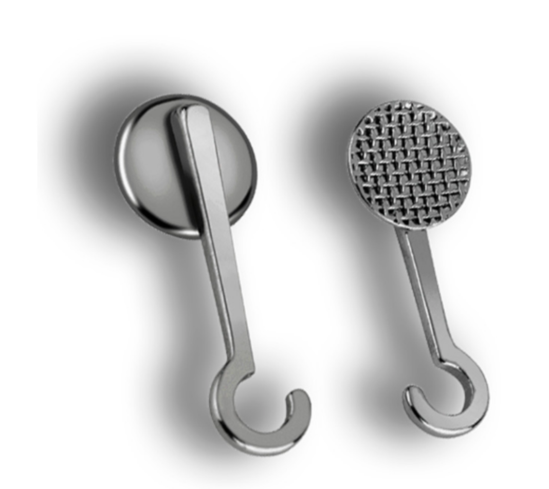
The power-arm [13] is a miniature device, which may have various designs depending on the place of bonding, which can be either tooth surface or the orthodontic wire. Currently, the most frequently used power-arms are prefabricated ones (Figure 1).
The orthodontic power-arm intended for the tooth surface has a part with a bonding surface for attachment to a tooth. This part is called a base, which could be either prefabricated (slightly curved) or individualized (exactly matching a particular tooth surface). The base is intended for a vestibular or lingual tooth surface. An arm of the power-arm extends gingivally and is intended for engaging a tractive device (usually elastic bands). The length of the arm is different depending on the distance between the place bonded and the center of resistance of that particular tooth. It also provides a leverage to a force vector applied to the end of the power-arm, enabling the preferably orthodontic bodily tooth-movement. After bonding, it must by resilient, aesthetic, and compliant with intraoral anatomy, providing an anchorage for intraoral elastics to control the application of the biomechanical force vector on the tooth.
Oral anatomy varies in everybody. This is the reason for frequent debonding or extreme compromises in applied universal devices (reducing their biomechanical effectiveness). Individualization is the key. The last four years of our clinical experience with 3D printed power-arms revealed that the interference of power-arm with gums, intraoral tissues, or other teeth in the occlusion results in the damage or debonding of the power-arm. Absence of the individual base where tooth-surface curvature is compensated with extra adhesive also reduces the strength of the bond between the power-arm and the tooth surface [14]. The importance of individualized bases is the fundamental aspect of effectivity for most customized intraoral appliances, such as lingual orthodontic brackets, 3D printed hyrax devices or power-caps, and power-arms [15].
It is not only existing anatomical objects in the oral cavity that might interfere with a power-arm. For example, food and its processing are possible threats to power-arm retention. To respect the masticatory and articulative functions of oral cavities, the bio-inspired design of the power-arm shall work in harmony with these, whilst at the same time respecting smile aesthetics, and preserving resiliency and biocompatibility. The current topics in biocompatible 3D printing in orthodontics are frequently focused on the direct 3D printing of clear orthodontic aligners or retainers. 3D printed retainers were, until now, preferred to be 3D printed from Remanium (Co-Cr) alloys [16,17].
Universal power-arms suffer from frequent debonding, patient discomfort or necessity to reshape or position them in a way that compromises their biomechanical effectivity [14,15]. The customized power-arm has details which cannot be properly or economically manufactured in the subtractive manufacturing process. As the power-arms are exposed to the oral cavity for a long time, they must be at least class IIa biocompatible certified. To facilitate a tooth movement in the proper direction, they must translate the force from the intraoral elastic band efficiently. The base of the individualized power-arm matches the exact tooth surface. This provides not only the perfect bonding contact, but also enforces the proper positioning of the power-arm on the specific spot, due to the unique complementarity between tooth and power-arm surface. This is how the individual base of the 3D printed power-arm guides itself to proper positioning, as planned in the virtual setup.
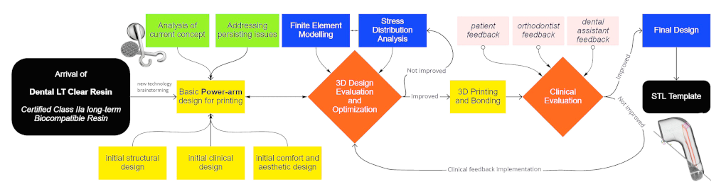
The purpose of this work was also to inspire that such AM workflow is available for the designing or redesigning of any customized intraoral biomedical appliance. Moreover, that process can be completed upon the combination of technical and clinical research, as evidenced in Scheme 1.
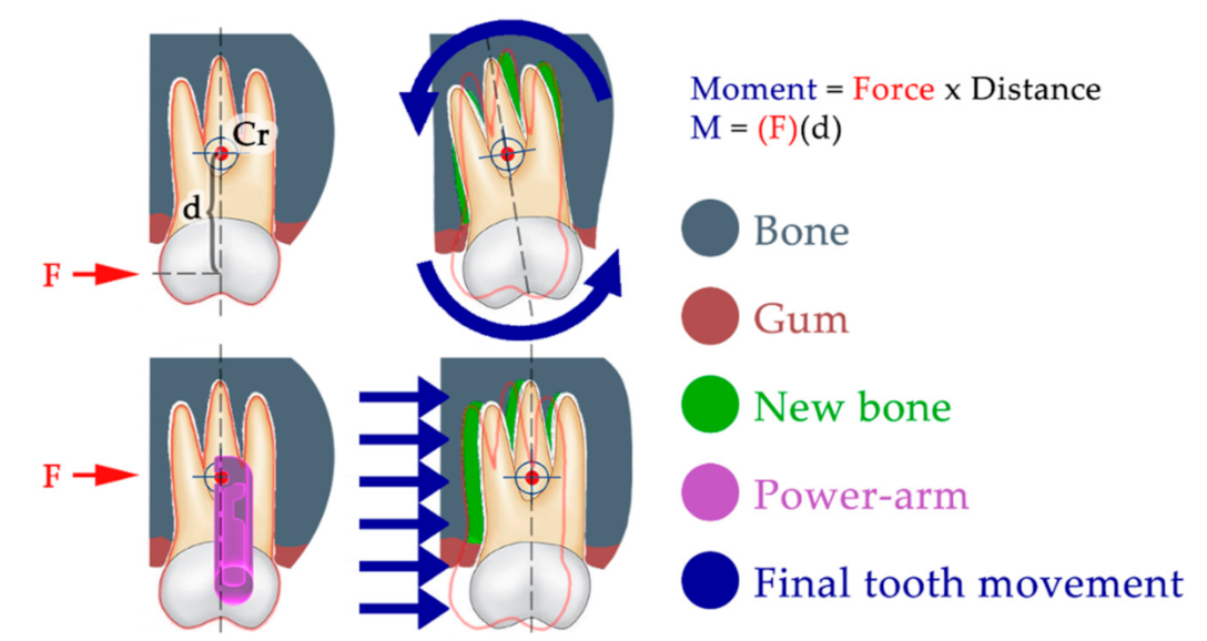
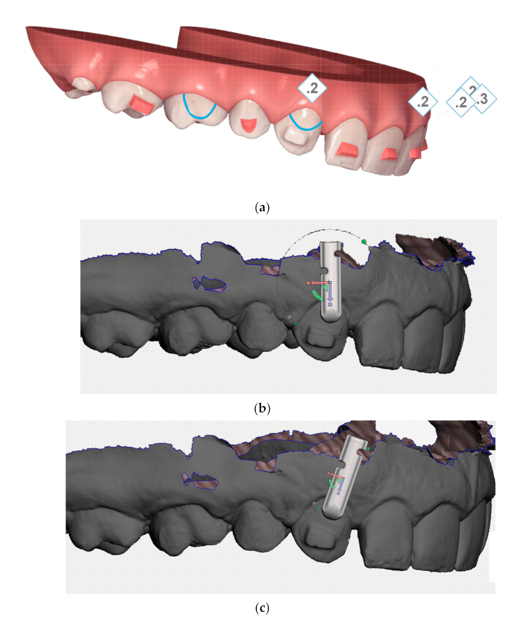
The power-arm is not an essential feature of every orthodontic treatment. However, in difficult tooth movements, it is a crucial tool. Especially in biomechanics, where forces must be applied close to the tooth’s center of resistance to avoid tooth tipping. The power-arm-enabled biomechanical approach offers a critical instrument for treatment efficiency. Figure 2 explains the importance of controlled force application in regard to the center of tooth resistance, which can result in significantly different clinical outcomes. The center of tooth resistance (Cr), also called the center of tooth rotation, is a virtual point around which the tooth rotates when force is applied to its crown. This point is not approachable directly, as it is usually located in two-thirds of the length of the root. Its location always differs, as it strongly depends on the level of surrounding bone, as well as the root length and shape. When force is applied to a tooth crown (above the Cr), the tooth movement is described as tipping, which is frequently undesirable. When force is applied at the level of Cr, the resulting tooth movement is described as bodily movement. This is the orthodontically preferred movement. This type of tooth movement is crucial to treatment predictability and efficiency.
Our aim with this research was also to inspire new ideas for manufacturing individualized devices not just for orthodontic tooth movement. The use of mathematical modeling and simulations of material stress upon load is a useful step to improving the intraoral resiliency of any 3D printed intraoral appliance. Our clinical observation of the resiliency of AM appliances provides further information about the material’s long-term behavior in hostile environments, such as in oral cavities [9].
The correction of malocclusion is performed by moving the teeth to ideal positions and inclinations. One of the main problems associated with moving teeth is that the roots of the teeth need to be moved together with the tooth crown. The roots are deep in the alveolar bone and are inaccessible to common orthodontic biomechanics. For this reason, it is necessary to apply gentle and continuous forces of orthodontic leverage to the roots, and these can be applied only on visible and accessible parts of the tooth—the tooth crown. To be effective in orthodontic treatment, we need effective biomechanics. To achieve effective biomechanics, we need to translate the biomechanical vector of the force as close to the center of resistance of the tooth as possible. This center of resistance of the tooth is located approximately in two thirds of the length of the root. To have this leverage, we use the so-called power-arms. These arms have a body which includes a connecting surface for connection to the surface of the tooth crown, which we call the base. The arm is blade-shaped and is also provided with a plurality of recesses in the medial or distal edges of the arm, which serve to connect the traction device—the elastics. Power-arms are not new to orthodontics [8]. The possibility to create them with AM is exciting, and the opportunity to have them fully individualized is inspiring.
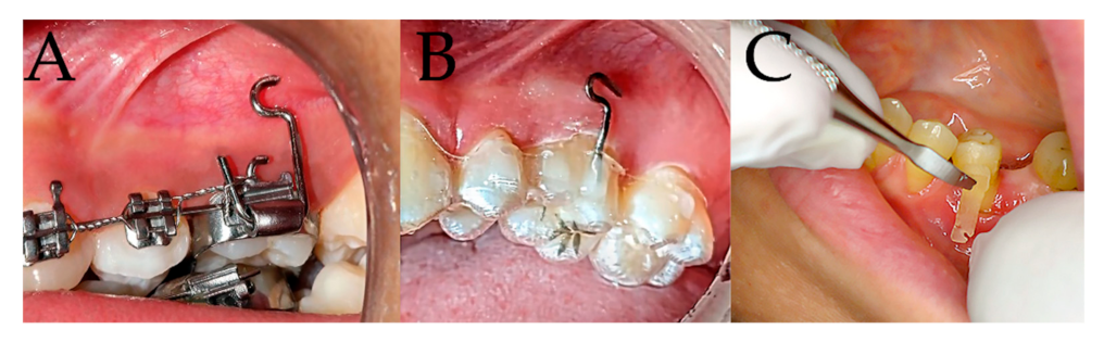
In our work, we have focused first on gaining knowledge about the strength and durability of currently used prefabricated metallic power-arms. In the past, the power-arms were bent from orthodontic wire and, as “power” arms reference, were a commonly used features with the Straight Wire appliances. An article from 1986 describes their employment to advantage in the old orthodontic Begg technique, supporting the extraction space closure from behind [18]. For the last two decades, power-arms have been frequently used as prefabricated, mostly metallic, orthodontic features, [19,20]. The clinical experience (
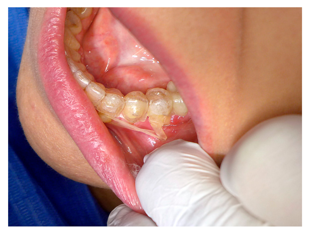
Figure 3A,B) of our orthodontist with metallic hand-crafted and prefabricated power-arms (Figure 1) references the following frequent impediments:
  • Patient discomfort;
  • Loss of power-arm attachment;
  • Aesthetic handicap.
As there was no other type of orthodontic power-arm until now, the existing varieties of hand-crafted and prefabricated were used. There is no mention in the literature about any 3D printed orthodontic power-arms with an individual base. Comparing the developed approach to the current state-of-the art power-arms produces promising results. The current state-of-the-art interdisciplinary research concerning power-arms employs finite element analysis to focus the research more on the ideal power-arm placement on the tooth surface or the power-arm length [21,22]. Most of the research is not concerning the power-arm shape. This paper is reporting the current, state-of-the-art approach to designing new 3D printed power-arms, upon technical and also clinical analysis. The new design addresses the current clinical limitations of hand-crafted or prefabricated power-arms. The presented workflow, based on AM, is applicable to other intraorally applied medical devices and shall be encouraging for other innovators [23].
The aim of this study was to design and materialize the functional shape of a comfortable and transparent orthodontic power-arm by means of biocompatible 3D printing. The shape needs to withstand the environment of the oral cavity, as well as not only the forces applied by the elastics during orthodontic treatment, but also chewing forces.

2. Materials and Methods

2.1. Data Collection

  • For technical evaluation:
From five 3D printed bar samples of Dental LT Clear Biocompatible Resin, the tensile test was performed on all samples, then the test was repeated, and only 2 specimens were usable for evaluation [24].
  • For clinical evaluation:
    50 patients with 3D printed variant 1. power-arm were observed and evaluated.
    50 patients with 3D printed variant 2. power-arm were observed and evaluated.
    Each patient was labeled with a number and the following data were collected:
    • Variant of power-arm (1/2);
    • The tooth with observed power-arm (only one observed per patient);
    • Debonding incident—days since last bonding (when empty = no loss of attachment);
    • Months after which the power-arm was naturally removed;
    • Remark (special notice—for example, we have observed 2 deboning in patients who were excessively using Listerine mouthwash, one case in each group).
After 60 days (continuous) without loss of the PA attachment, the scientific observation of the power-arm was evaluated as “without loss”. In some clinical cases, the power-arm achieved the clinical goals and was intentionally removed.
At the beginning of our research, it was necessary to collect data on currently used, individually produced power-arms, which were used in clinical practice. These power-arms were 3D printed from a biocompatible resin. The difference between these individualized power-arms and the commercially used prefabricated power-arms is the material used and the shape of the power-arm itself. The shape of the power-arm is straight in the longitudinal axis of the arm, but the base, by means of which the power-arms are bonded to the tooth surface, is always the same (Figure 1). Due to this fact, prefabricated power-arms must be bonded to the tooth surface in, not always ideal, positions. This fact is not very advantageous in the principle of predictable orthodontic therapy. In all cases, we have used an intraoral digital scan of the patient’s oral cavity, so we were able to produce an individualized surface of the base of the power-arm. This surface ensures that the bonding of the power-arm is only possible in pre-planned position and orientation as modeled virtually by us in advance. This ensures the correct application of force to the tooth surface and the achievement of a suitable therapeutic result.
Collection of clinical data for the evaluation of the intraoral situation and the power-arm retention was conducted during the patient’s personal visits to an orthodontist. The secondary observation method was accomplished by means of dental-monitoring software technology, which is a telemedical solution that employs artificial intelligence algorithms to notice debonding or damage to the bonded power-arm and alarm the clinician upon such findings.

2.2. Development of the Power-Arm

The original biocompatible 3D printed variant of the power-arm with a more rectangular base, that was regularly used by clinical practice, suffered from frequent structural failures in the sense of longitudinal rupture in the area of the attachments for elastics. Pressure from these elastics (rubber bands) was not only damaging to the original variant of the power-arm (Figure 4). Breakage in the region where the arm disconnected from the base was frequently bitten of. The original (variant 1) of the 3D printed power-arm suffered a failure within a week after bonding, approximately every fifth case. This is not clinically sustainable. Such a failure of the power-arm requires another patient visit in the dental office, and entails cleaning the surface of the tooth from remaining glue and the new bonding of another clone of the power-arm. The damaged power-arm is replaced in this process. The decision to redesign the original, variant 1, was followed by design research. In order to be able to develop a stronger variant, it was necessary to analyze the original model. Since the original version was only available in the Standard Tessellation Language (STL) format, we first had to redraw the force arm into a more suitable digital format that can be used with computational design programs. Such a format, in our case, was the Standard for the Exchange of Product Data (STEP) format, which was compatible with SolidWorks software (from Dassault Systèmes SOLIDWORKS Corp.), and the subsequent calculation program in our case was the Finite Element Method (FEM) software, described in Section 3.2.

2.3. Development Environment

SolidWorks is a popular modeling program that uses a parametric approach based on features originally developed by PTC company to create models and assemblies. This software is written on the Parasolid kernel. Parameters apply to constraints whose values determine the shape or geometry of a model or assembly. The parameters can be either numerical parameters, such as line lengths or circle diameters, or geometric parameters, such as tangents, parallel, concentric, horizontal or vertical, etc.
Model creation in SolidWorks usually begins with a two-dimensional (2D) design. The sketch consists of geometry, such as points, lines, arcs, cones (except hyperbola), and a spline. The parametric nature of SolidWorks means that dimensions and relationships control geometry, not the other way around. The dimensions in the sketch can be controlled independently or through relationships with other parameters inside or outside the sketch. Finally, it is possible to create drawings from either parts or assemblies.

2.4. Three-Dimensional Printing and 3D Modeling Environment

2.4.1. Three-Dimensional Printer—FORM 2 from FORMLABS

We have used the 3D printer FORM2 from the company FORMLABS. Formlabs is a 3D printing technology developer and manufacturer located in Somerville, Massachusetts. This 3D printer uses SLA technology (explained in the Introduction section). Each point of the layer is cured with the laser beam. We printed from biocompatible certified material at the resolution of 100 microns [24].

2.4.2. Three-Dimensional Printing Resin

We have used certified Dental LT Clear Resin (RS-F2-DLCL-01), which is used in dental practices and labs to rapidly manufacture a range of dental products in-house, from biocompatible surgical guides and splints to fixed prosthetic and clear aligner models. Dental LT Clear Resin is a class IIa long-term biocompatible resin ideal for hard splints, occlusal guards, and other direct-printed long-term orthodontic appliances. This clear material polishes to a high optical transparency. It has an improved durability and resistance to discoloration over time. It supports the print resolutions of 100 microns and needs postprocessing after 3D printing. The chemical composition of this material is presented in Table 1. The updated version 2 of this biocompatible resin is currently commercially available. Its safety data sheet is published online, according to Regulation (EC) No. 1907/2006 (REACH) with its amendment Regulation (EU) 2015/830 including information on handling, storage instructions and toxicological information.
The new (2nd) generation of this dental biocompatible resin, which is currently available, has its technical data sheet public; Dental LT Clear is tested at NAMSA, Chasse sur Rhône in France, and is certified biocompatible per EN-ISO 10993-1:2009/AC:2010. The resin is in compliance with ISO Standards: • EEN ISO 1641:2009 • EN-ISO 10993-1:2009/AC:2010 • EN-ISO 10993-3:2009 • EN-ISO 10993-5:2009 • EN 908:2008. As material properties of new resins are now publicly available, there is no necessity to repeat our material analysis to research flexural, hardness and impact properties of the resin. Doctors can use this information directly from material data sheets and use them in modeling their appliances.

2.4.3. Three-Dimensional Print Postprocessing—Form Wash and Form Cure from FORMLABS

We used a dedicated automatic wash for the 3D prints with Isopropyl alcohol (2-propanol), also known as isopropanol (IPA). Once washing is complete, Form Wash automatically lifts parts out of the IPA, avoiding over-soaked, warped prints. Parts air dry and are moved to Form Cure which contains 13 multi-directional LEDs that emit the optimal wavelength of 405 nanometers light for curing Formlabs materials. A rotating turntable provides uniform exposure during post-curing and an advanced heating system precisely controls curing temperatures up to 80C. Three-dimensional printing procedures and the processing of printed parts is described in Table 2. After 3D printing, the power-arms were placed in a Form Wash filled with isopropyl alcohol (IPA, ≥96%) and rinsed for 20 min. The parts were allowed to air dry thoroughly for 30 min. Clean and dry parts were then processed with post-curing. Power-arms are required to be fully post-cured for biocompatibility and optimal mechanical properties. They were post-cured by exposure to UV light. Cure time depends on the wavelength and intensity of the light used. In our case, the certified method for post-curing is exposure for 10 min to 108 watts each of Blue UV-A (315–400 nm) and UV-Blue (400–550 nm) light, in a heated environment at 60 °C.

2.4.4. Finite Element Method (FEM)

Effective engineering is now unthinkable without the qualified use of computer technology. In this complex Finite Element Method (FEM), in the field of strength calculations, it cooperates most closely with the means for design (CAD) and simulation of mechanical systems (MSS). FEM parts (especially linear strength solutions) are often already an integral part of CAD systems.

2.5. Principle of the Method, Basic Concepts and Basic Steps of Solving the Problem

2.5.1. General Overview of Analyses

CAD model with material properties is required for 3D strength analyses using the finite element method (FEM). The analysis of the model takes place in a certain order. First is the preprocessing. Preprocessing is the preparation of a model, which consists in modifying the geometry. By this adjustment we mean the adjustment resp. edge rounding, chamfering and radius removal depending on the result we need to calculate. The next step is “meshing”. Meshing is the division of a body into smaller elements. The last step is to determine the material properties, such as the modulus of elasticity of the material E, the Poisson’s ratio, or the yield strength. After all this, we can proceed to the calculation itself and postprocessing analysis. Postprocessing analysis involves examining the results of deformations, stresses, and the determination of critical points.

2.5.2. Measurement of Mechanical Properties of Resin

The orthodontic power-arm was 3D printed from Dental LT Clear Resin (RS-F2-DLCL-01), a class IIa biocompatible resin from Formlabs. The manufacturer states only partial mechanical properties of the material, and these were insufficient to enter the proper strength analysis. Therefore, for the accuracy of the analysis, we decided to experimentally measure the modulus of elasticity E and the ultimate strength Rm of said material. Our 3D printing and post 3D printing processing was exactly as recommended by Formlabs manuals [24]. Postprocessing included Form Wash and Form Cure (post-curing is required) procedures, as described in the Section 2.4 [25]. The three-dimensional printing resolution was 100 microns.
To determine the mechanical properties of Dental LT Clear Resin, 5 samples with dimensions in mm were printed according to (Figure 5) [26].

2.5.3. Tensile Test

The tensile test was performed on the machine type: DESK 5kN (Figure 4 and Figure 6).

2.6. Principle and Method of 3D Modeling of the Individual Base

To create an individual base in a power-arm, any free, simple modeling software can be used, as this process does not require a special 3D modeling skillset. In our case, we used Autodesk Meshmixer software (Figure 7a–e).
  • First step is to import intraoral scan, usually in STL format, and also a universal 3D model of power-arm (variant I (Figure 8) or II) with generic base;
  • Second step is to position the power-arm as clinical aspects require, with respect to patient oral anatomy;
  • Third step is to apply Boolean Difference subtraction of tooth shape from the generic base of the power-arm. This results in individual base of the power-arm, that shall be finally exported as STL and 3D printed.

3. Results

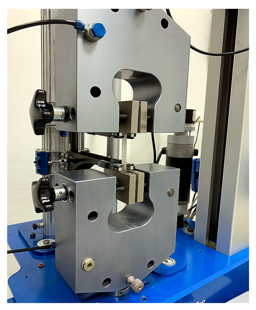
3.1. Tensile Test Results

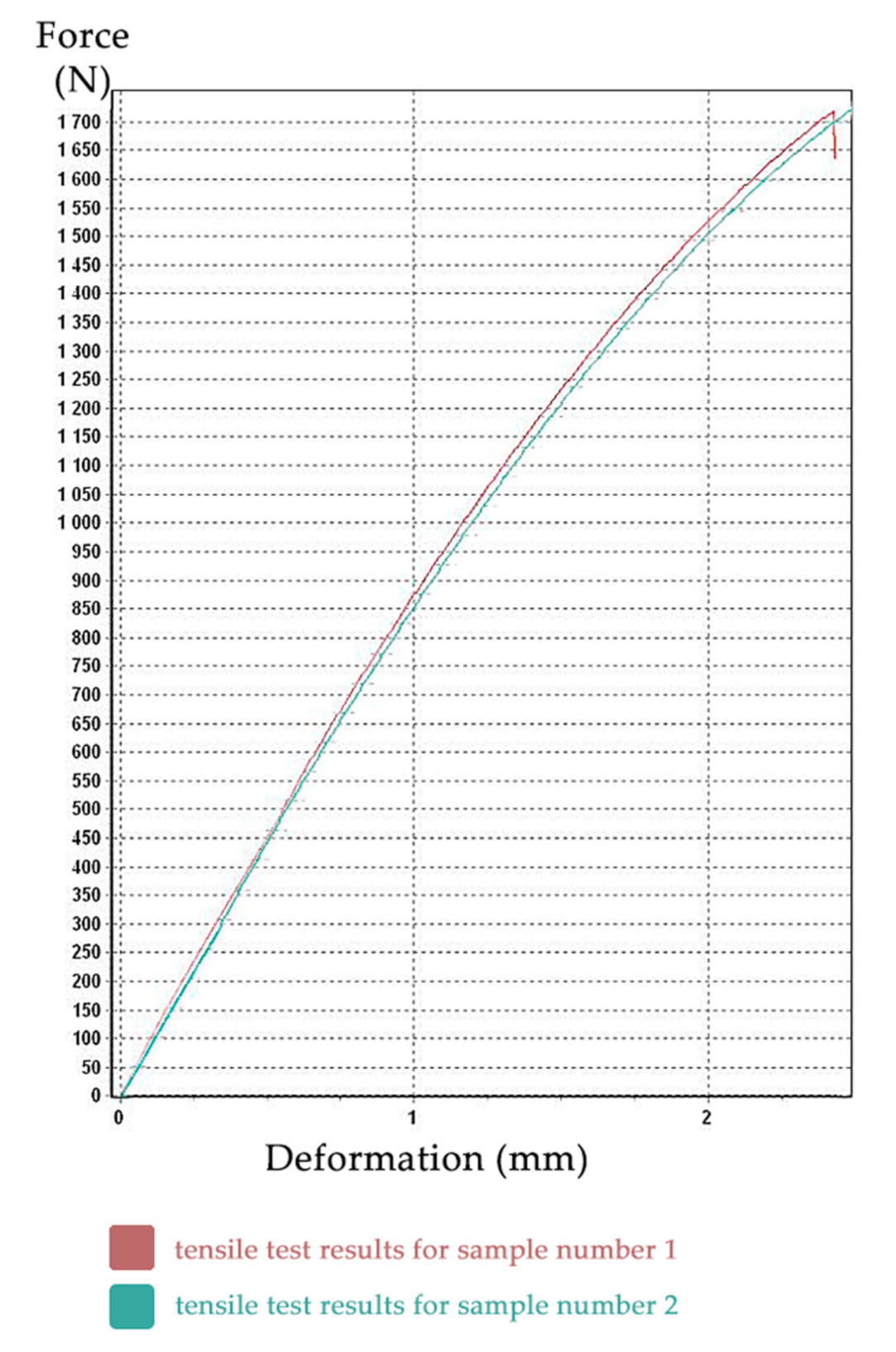
The tensile test was performed for all samples, but the last three samples were incorrectly clamped, so the results from these three specimens were unusable. Full probing dataset is available. The resulting tensile test diagrams of specimens No. 1 (red) and No. 2 (aquamarine) are shown in Figure 9. The X-axis shows the deformation (in mm), the Y-axis shows the force (in N).
Other outputs of tensile tests were also text files with measured values, such as: time (s), force (N), travel (mm), elongation (mm), tensile stress (MPa), and relative elongation (%), etc.
These values were processed using Microsoft Excel 2016 and subsequently, using Hooke’s law, the modulus of elasticity for the first two samples was calculated. As seen in Figure 9, the curves are slightly different and are shifted in the Y axis. The values of the modulus of elasticity of sample No. 2 were trivially lower. This slight difference is not clinically relevant for medical application. However, as the clinical objective was to design a more resilient power-arm, we have conservatively chosen this second (lower) sample as representative.
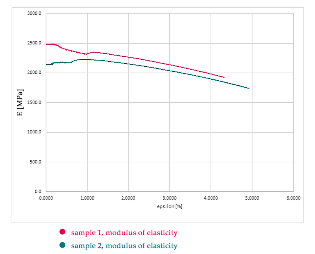
The modulus of elasticity (Figure 10) was calculated as the arithmetic mean of all values of the modulus of elasticity from test sample No. 2 and its value is 2089 MPa (see Figure 9). During the testing, the transverse deformations of the sample were not recorded, so it was not possible to determine the Poisson’s number, and therefore we chose the value 0.29 in the calculation. The international standard that specifies the general principles for determining the tensile properties of plastics and plastic composites under defined conditions is: ISO 527-1:2019 [27]. ISO 527 standard, belonging to the family of plastics standards, specifies the test conditions for the determination of the elastic limit, the deformation, the permissible loads, and the type of breakage of the materials of plastic composite, isotropic or orthotropic, and fiber-reinforced, when subjected to tensile stress. These results were not researched upon the test conditions defined in ISO 527. This norm, updated in 2019, is appropriate for the determination of the tensile properties of plastic composites of unknown composition and mechanical properties.
The step of researching material properties in this research is shown only for information purpose for clinicians experimenting with unknown materials. This paper is intended for medical clinicians to increase their awareness about possible approaches to designing their personalized intraoral appliances. The authors of this paper want to emphasize that testing two specimens is too little for proper material design. As the material properties of Dental LT Clear Biocompatible Resin (version 1) have been confirmed by the manufacturer during the research process, there was no need to print more specimens. This would be otherwise compulsory in research of material mechanical properties. Clinical use of unknown materials can be allowed only under special strict circumstances. Dental LT Clear v1 was tested at NAMSA, Chasse sur Rhône in France, and is certified biocompatible per EN-ISO 10993-1:2009/AC:2010. However, the production of this material is already discontinued, and its version 2 is now commercially available with full material properties’ data available (link on the technical sheet: [24]).
Researching material properties requires interdisciplinary cooperation and is feasible for medical clinicians. However, it is probably not necessary anymore, as every biocompatible resin, certified for clinical use, is required to publish full material properties suitable directly for FEM.

3.2. Calculation Program and Model Preparation

A software package from ALTAIR company was chosen as a calculation program, which contains a preprocessor (HyperMesh = preparation, discretization of the model, assignment of mechanical properties and boundary conditions). The calculation itself was performed in the program Optistruct, linear solver (sol. 101) and, subsequently, postprocessing was conducted in the program HyperView.
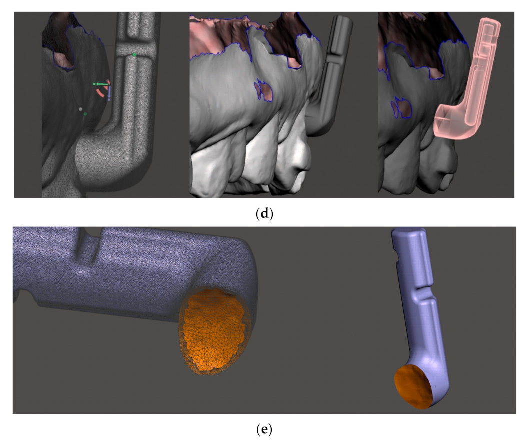
3.3. Input Geometry

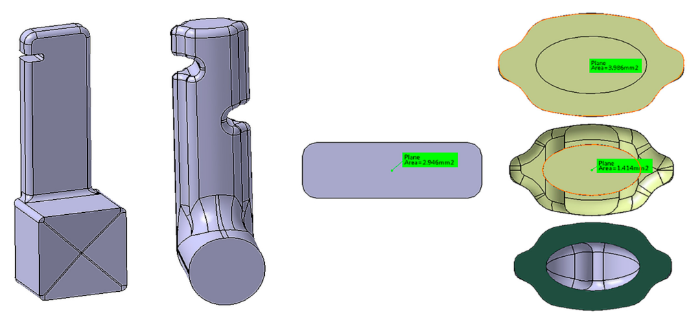
Figure 11 on the left shows the original geometry of the power-arm (variant I). This variant, as already described earlier, frequently broke at the top notch in the arm due to insufficient material thickness in the area and the effect of lateral tensile forces. The SolidWorks program, which we used to modify the original geometry to a new one (hereafter referred to as variant II), with the following:
-
a notch was added to hold the rubber band on both sides (better usability), the notch was widened, and the internal angles/edges were more rounded.
-
the edges have been rounded, so the food retention shall be less frequent, and variant II shall be less mechanically irritating when in contact with the tongue, oral mucosa and the lips.

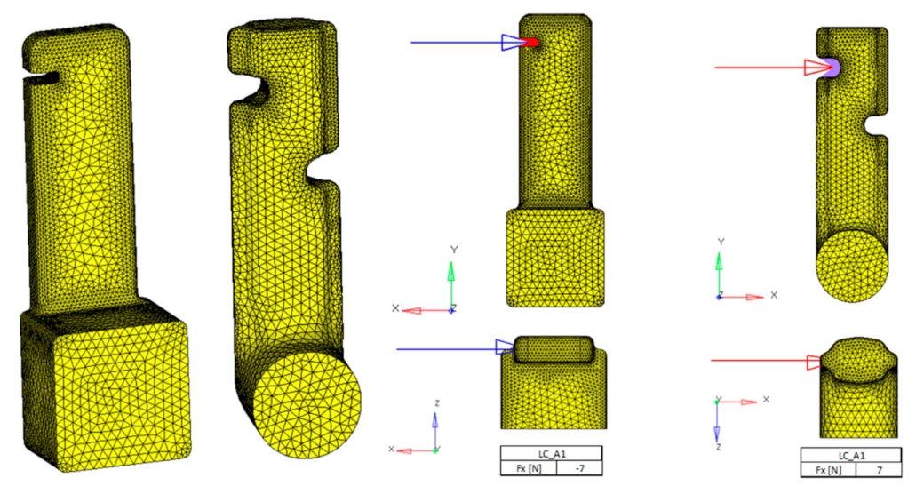
3.4. Discretization (Meshing), Boundary Conditions and Material Properties

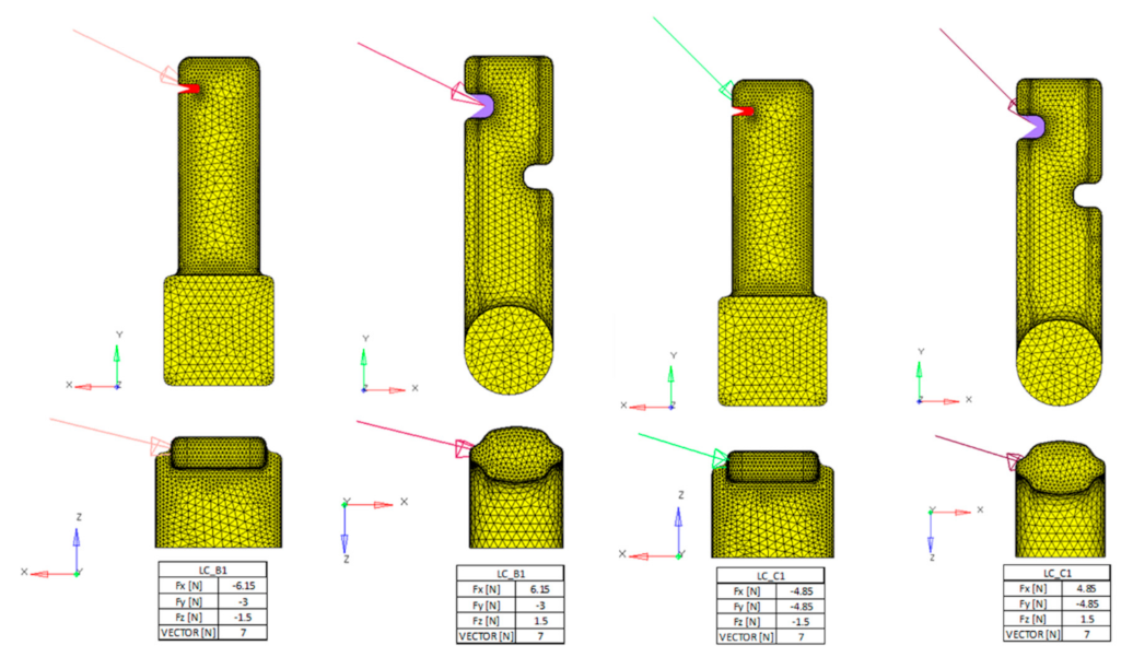
Figure 12 shows finite element models. CTETRA elements (4-node tetrahedron) were used. The number of which, in the critical places of the component (edges, notches, radii), is smaller, in order to better absorb the stress.
We used three loading conditions. The loading conditions were chosen upon the clinical aspect and intended use of the power-arm. The spot of elastic-band insertion is precisely recognized, as is the base pad, which is intended for adhesive attachment to the tooth surface. We tried to load both variants with identical forces. In each load case, the resultant of the forces was 7 N. In the second (LC_B1) and third (LC_C1) load cases, the direction of the force vector differed.
LC_A1 = load in X direction (Figure 12);
LC_B1 = spatial load (Figure 13);
LC_C1 = spatial load (Figure 13).
We have used the material properties of dental biocompatible resin measured by us, namely:
Modulus of elasticity in tension E = 2089 MPa;
Poisson’s number ν = 0.29;
Ultimate strength Rm = 83 MPa;
For sample No.1 Rm = 83.09 MPa, for sample No.2 Rm = 85.5 MPa.
The calculation was performed in Optistruct, linear solution 101 (Solution 101). Due to the size (39,525 degrees of freedom for variant I and 26,802 degrees of freedom for variant II) and type of the task, for today’s computer performance, it was calculated in a matter of seconds. A linear elastic material is a mathematical model used to analyze the deformation of solid bodies. When the loads are removed, the material naturally returns to its original, undeformed shape. In other words, the material stress level doesn’t reach the ultimate strength limit. The linear elastic FE analysis is an efficient modelling approach for our power-arm virtual model modeling. Oral masticatory functions can deform PA, which would result in an undesired clinical effect. As this paper is aimed at medical clinicians, it shall be considered what masticatory pressures will affect the intraoral appliance, their intensities, directions and other characteristics. This is different for each intraoral personalized device.

3.5. Postprocessing

The results were loaded into the HyperView program, which offers a wide range of assessments of various stresses (von Mises, mainly stress, and maximum shear stress).

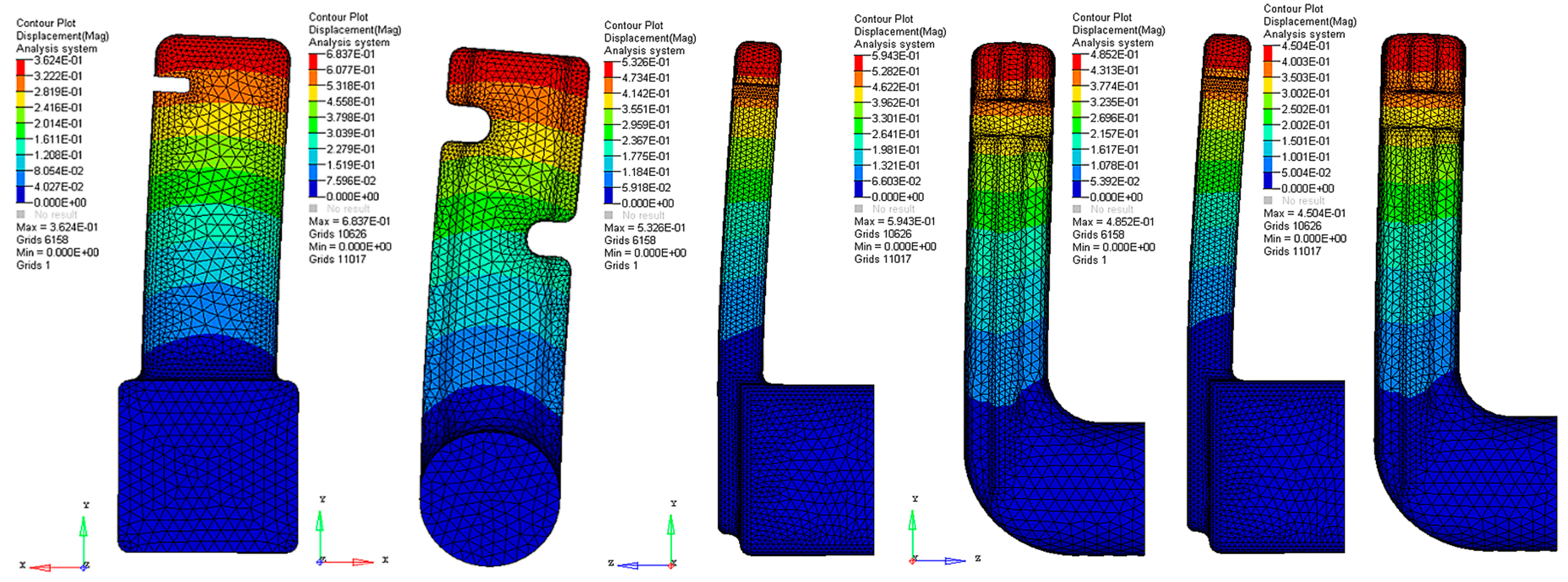
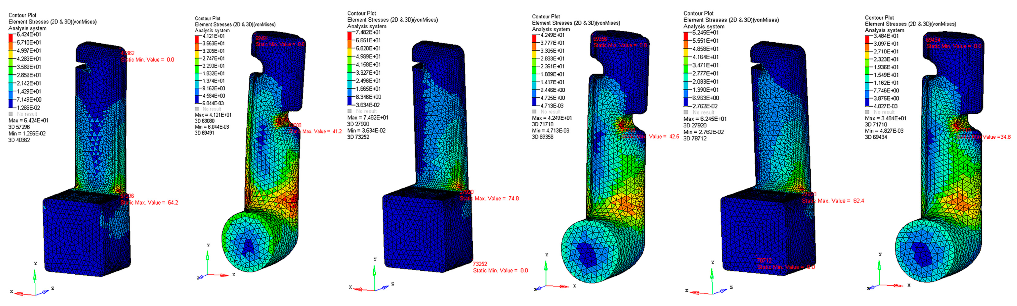
3.6. Deformation Stress in the Arm

Figure 14 and Figure 15 describe stress under various loading conditions. The loading conditions were chosen upon the clinical aspect and intended use of the power-arm, as the spot of the elastic-band insertion is known, as well as the base attachment to the tooth surface.

3.7. Analysis of Technical Aspects of the Results

As mentioned above, for the brittle material (our case), the von Mises method was chosen as the method for stress evaluation. The following applies to the given power-arms:
The major difference between variants in deformations is for the load LC_A1, however, the probability of its realization is very small (the force acts only in the direction of the X-axis).
The probability of loading LC_B1 and LC_C1 is very high, but here the difference between the deformations is negligible. The stresses in contrast to the deformations are considerably higher for variant I, which means that variant II is stiffer and shall be more resilient. Clinical aspects of PA loads are known; Table 3. summarizes the differences between both PA variants under various loads.
In the case of load LC_B1, variant II is 11% more flexible (less rigid) compared to variant I, but the stresses for variant I are 76% higher than for variant II.
In the case of load LC_C1, variant II shows overall higher stiffness and lower stresses than variant I, namely:
Variant I is 7% more flexible and shows higher stresses of up to 82% compared to variant II.

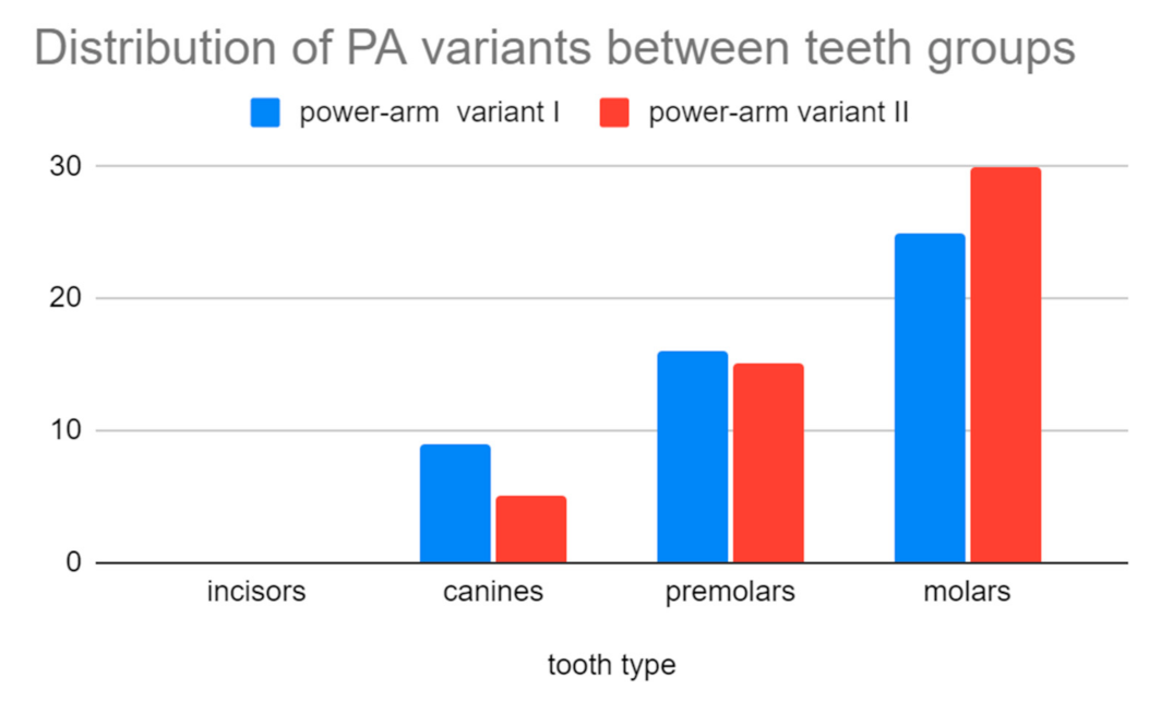
3.8. Analysis of Clinical Aspects of the Results

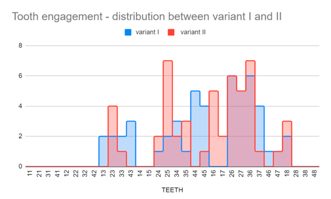
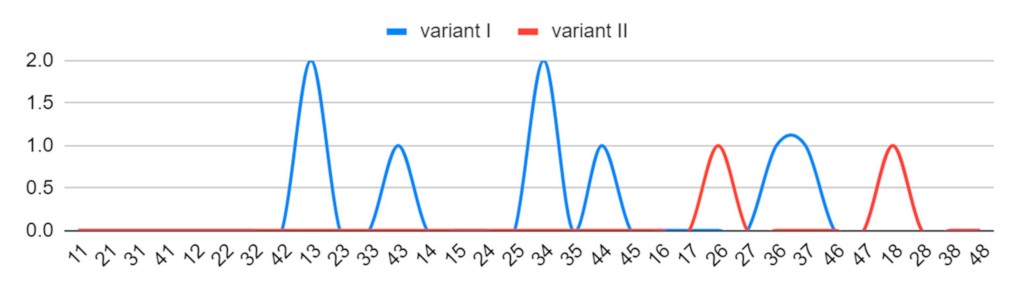
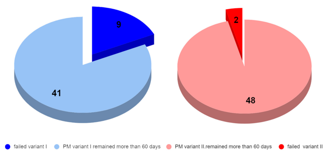
Clinical application of the power-arms was always incorporated to the complex orthodontic treatment plan. There was a clear benefit for the patient biomechanics and two groups of 50 applications were formed. A total of two designs of customized power-arms were used (variant I—older, variant II—newer). Only one power-arm per individual was observed. The indications of particular variants of PA (variant I/II) were random. A total of 50 older and 50 improved designs were applied and observed. The data were analyzed for normal distribution between both groups. Teeth used for PA placement were grouped to four main groups according to their type (incisors, canines, premolars, and molars). PA fractures, deboning or another damage was evaluated as failure.
Frequency of failures between groups was evaluated by two tailed T-test.
Hypothesis 0 (H0).
The Null Hypothesis was that there is no significant difference between the power-arm designs’ clinical performance.
Hypothesis 1 (H1).
Alternative Hypothesis was that there is a significant difference between the clinical performance of one of the PA designs. By convention, two-tailed tests are used to determine significance at the 5% level, meaning each side of the distribution is cut at 2.5%. Before comparing both groups, data distribution was evaluated.
Figure 16 and Figure 17 (Supplementary Materials) visualize distribution of PA variants between main types of teeth.
We were comparing two groups (PA variant 1 and 2) and have quantified the difference between them with a two-tailed T-test determining significance at the 5% level. This means that each side of the distribution is cut at 2.5%. We have also assumed that the variation of data in both sets were not the same.
Calculated p value of two tailed T-test was 0.0260.
A p-value less than 0.05 (typically ≤ 0.05) is statistically significant. It indicates strong evidence against the null hypothesis, as there is less than a 5% probability that the null is correct.
Clinical application of the power-arms was always incorporated to the complex treatment plan. A total of two groups of 50 applications were chosen randomly. Only one power-arm per individual was observed. Table 4. summarizes the clinical evaluation. Figure 18 and Figure 19 (Supplementary Materials) visualize the different clinical performances of the older and newer power-arms.

4. Discussion

Designing and manufacturing one’s own patient-customized designs in dentistry is not new. In fact, this is a modus operandi for orthodontics since its beginnings. With the power of AM, together with digital intraoral scanning, we can engage the trajectory of even greater treatment individualization. This will result in higher treatment predictability and efficiency.
The results showed that with proper analysis, the current designs can be improved towards the higher resiliency of biomedical devices applied intraorally. Three-dimensional biocompatible printing can achieve outputs which are not only biomechanically fully functional but are also more effective than handmade devices [25,26,27,28,29,30]. Results of this study revealed that redesigning the shapes in concordance with biocompatible material properties can provide a more resilient device. Orthodontics as well as dentistry are undergoing a technological revolution, with advances in medical imaging, 3D printing and customization of appliances [31]. Future research directions may cover another customized device. We are already researching the possibilities of how to improve our current biocompatible designs of the biocompatible 3D individualized retainer (“bio3dir”), “power-cap” and “carriere-distalizer”. Digital workflows are currently trending in the orthodontic practice. They have affected every aspect of orthodontics—with transformations in documentation, study casts, analysis of dental malocclusion, smile designing, treatment planning and for fabrication of orthodontic appliances. The three-dimensional imaging of dentition, skeletal components and the face allows treatment planning in 3D and the use of computer aided design (CAD) and computer aided manufacturing (CAM) for customization of orthodontic appliances. Software integration of digital models, 3D facial imaging and cone-beam computed tomography (CBCT) makes it possible to simulate the treatment plan and to attain good communication with the patients. [31,32,33].
Biocompatible resins are not strongly dominating the AM field of dentistry. Frequently porous titanium alloy structures are more suitable for use in biomedical applications when resilience to forces is necessary [34]. However, the power is placed visually on the teeth’s surfaces, so its aesthetical aspect is very important, and titanium or Remanium alloys are not suitable from this aspect.
There is an important part of the orthodontic profession focused in care for cleft patients. Biocompatible 3D printing can affordably provide them with a sequence of customized biocompatible appliances to compensate anatomical defects before surgical interventions are performed. There are different time-protocols of cleft lip and palate operations. Especially in the first few months before surgery, compensation with a customized appliance is needed [35].
Power-arm designing based on stress distribution analysis with finite element modelling research was a specific task. In the past, the use of stress distribution analysis in real components and also in the finite element modelling were challenging procedures that required sophisticated infrastructure. Such research is still inter-disciplinary; however, it is quite accessible. Product analysis is a commonly used production process for metal alloys. The resin we have used did not have its complete technical data published by its manufacturer at the time of this research. We had to discover these data thanks to material analysis in the laboratory. Due to that, we cannot compare our power-arms with commonly manufactured ones, as commonly produced power-arms are made of metal alloys and have completely different material properties. After gaining knowledge about the properties of the material, we redesigned the shape of the prototype power-arms. The strength of each prototype had to be calculated by computer. After complete tuning, the spatial shape was finally modeled with a cavity inside. We managed to model power-arms using 3D printing without the prototype cracking. We managed to achieve our goal, which is confirmed by our calculations and clinically applied arms.
The disinfection of the 3D printed part is an important aspect to be discussed. As described in the Materials and Methods section, our procedures of power-arm disinfection were consisting of UV post-curing and IPA. The 3D printed power-arms are intended to be fixed in the oral cavity, which is not a sterile place. They are not considered to be implants which are required to follow strict rules, for example, prosthesis for hips or knees, dental implants, or spine screws [36].
Results of the analysis and design of increasing the tensile arm strength showed that deformations of the originally analyzed arm pointed to the strength deficiencies of the original model. The disadvantages were a weak layer of material in the notch area for the tension rubber and an insufficient amount of material for the vertical part of the arm under the application of lateral forces. This was followed by adjusting the shape of the base from square to circular to eliminate tension nodes. The vertical part was adjusted from a rectangular shape to a “lemon” shape. Thanks to this modification, we have achieved the largest increase in strength in our favor. The rounded edges and three-dimensional shape increased the tensile strength, especially in the lateral action of forces. We performed all strength calculations on FEM virtual calculation programs [37]. The finite element analysis was already used in orthodontic research; however, it was not applied to power-arm 3D design, it had merely been used to research an ideal power-arm location in the oral cavity [38]. We are not aware of any similar research in the world that has been published in regards to the 3D printing of customized orthodontic power-arms, that utilizes finite element modelling to upgrade an existing design of the individualized 3D printed power-arm.
As a result of the technical part of this research, we have managed to increase the strength by 7% and reduce the stress by up to 82%. The modifications we make increase the service life of the given component several times, which in practice means a lesser load for the attending physician, due to the need to glue a new arm, but also a lesser load for the patient.
The stress at the interface between tooth surface and the power-arm is important. One of the limitations of this study is the lack of analysis of this connection and adhesives [39].
Other limitations of this study are those characteristics of design and methodology that influenced the interpretation of the findings. For example, the individuality of behavior and eating habits of the patients has not been researched. These might have influence on result interpretations.
Considering other pros and cons of this new approach, another limitation is the technical and computer skills of doctors. Capability to perform technical analysis of the material requires interdisciplinary cooperation, however, the new trend is the online availability of all certified material properties regarding biocompatible resins for 3D printing. So, the advantage of this situation is that only FEM analysis for redesigning current individualized intraoral appliances will be necessary.
The novelty of the proposed approach rests not only in the biocompatible 3D printing of an intraoral appliance never 3D printed before, but also in the way of its individualization based on digital intraoral scans, and its redesign based on FEM analysis.
Today, there are many clinically applied customized intraoral appliances that might benefit from the described novel approach. It is the patients that will enjoy significant improvements in clinical performance of the intraoral appliances, such as 3D printed obturators in cleft patients, 3D printed hyrax and other devices in distraction osteogenesis, and many more.
This article shows medical clinicians, working with 3D printed customized appliances from certified biocompatible resins, that there are methods they can employ to improve their designs. Currently, the technical material datasheet is provided to all certified materials, so the material research is not necessary, and they can start directly with FEM modeling with data provided by the manufacturer. For redesigning an already optimized design, a convergence study should be done on FEM, as the mesh convergence is an important issue that needs to be addressed. It must be remembered that, when performing theoretical redesigning without planned clinical application and whilst experimenting with uncertified unknown materials, the material properties must be researched properly in compliance with ISO standards with significantly more specimens that two. The material research step in this article is for demonstration purposes only and the researched material parameters were confirmed by the manufacturer during this process (2019).
Dental LT Clear Resin (RS-F2-DLCL-01—version 1) used in this research is not produced anymore and was substituted with version 2 with all mechanical properties available (technical data sheet: [40]). However, this research is not focused on a particular material, it is about the redesigning and clinical evaluation of customized AM biocompatible appliances.
To better simulate all possible forces affecting the power-arm, this research could employ much more sophisticated technical solutions. For example, the modeling of possible combined axial–torsional non-proportional loadings that were used to simulate shape–memory alloys (SMAs) [40]. Though in our use case, where we are well aware of the force from the elastic band to the power-arm and also with the well-defined bonding area, more sophisticated methods are not clinically indispensable [41]. Moreover, topology optimization analysis in combination with shape and sizing optimization can be employed. We have also considered using artificial intelligence simulating material properties of the 3D printed object [42]. All these methods are possible and suitable for high-end engineering tasks, albeit not crucial for this level of guided power-arm redesign. In this clinical application, where every power-arm is positioned virtually by a doctor on the intraoral scan and then its shape is adapted to the clinical condition of the patient, this would also currently be an analytic overkill. Every 3D printed power-arm in every patient will be different and possibly even manually abraded with a dental drill in the oral cavity by an orthodontist. However, for future research, this is an interesting consideration. Possibly, with this new direction of using topology-optimized analysis, some other more sophisticated intraoral devices might be redesigned [42].

5. Conclusions

This research explored two significantly different clinical outcomes based on different 3D designs of 3D printed orthodontic power-arms. Clinical orthodontists can engage in better personalization of their intraoral biocompatible appliances. Results confirmed a significantly less frequent loss of PA attachment in the updated variant II. This tool will provide more predictable treatment outcomes and thus more efficient orthodontic treatment.
When comparing the 3D printed power-arms to current hand-crafted or prefabricated power-arms, we can conclude that biocompatible AM provides solution to many frequent impediments of non-AM power-arms, such as:
  • Patient discomfort (AM-PA have a more round-ergonomic design respecting individual patient anatomy because of the digital intraoral scan);
  • Loss of power-arm attachment (the individual base is superior to the prefabricated-one);
  • Aesthetical handicap (the power-arm is transparent and has an aesthetical advantage over metallic-ones).
As the result of this research is based on stress distribution analysis and finite element modelling, we have managed to increase the strength by 7% (in the new variant II) and reduce the stress by up to 82% in the more resilient 3D printed biocompatible power-arm (variant II). This has been confirmed by clinical evaluation of critical debonding incidents, where the new power-arm design (variant II) had approximately four times less frequent debonding and cracking than variant I.

Supplementary Materials

The following Supplementary Materials—full dataset—clinical evaluation is available online at https://www.mdpi.com/article/10.3390/app11209693/s1.

Author Contributions

Conceptualization, A.T. and I.V.; methodology, A.T.; software, F.K.; validation, L.C., B.N. and I.V.; formal analysis, F.K.; investigation, F.K.; resources, A.T.; data curation, F.K.; writing—original draft preparation, F.K.; writing—review and editing, A.T.; visualization, A.T.; supervision, I.V.; project administration, A.T.; funding acquisition, I.V. All authors have read and agreed to the published version of the manuscript.

Funding

This research was funded by the KEGA grant agency of the Ministry of Education, Science, Research, and Sport of the Slovak Republic (Grant No. 081UK-4/2021).

Institutional Review Board Statement

The study was conducted according to the guidelines of the Declaration of Helsinki, and no approval was necessary by the Ethics Committee. Ethical review and approval were waived for this study, due to the fact that no experimental materials or approaches were used. All used materials and machines were fully certified and are still available on the market. Dental LT Clear is tested at NAMSA, Chasse sur Rhône in France, and is certified biocompatible per EN-ISO 10993-1:2009/AC:2010. The biocompatible resin material is in compliance with ISO Standards: EEN ISO 1641:2009, EN-ISO 10993-1:2009/AC:2010, EN-ISO 10993-3:2009, EN-ISO 10993-5:2009, EN 908:2008. 3D printer—Formlabs Form 2 was the first and only stereolithography 3D printer to be validated by Materialise as part of the Materialize first FDA-cleared process to create accurate patient-specific anatomical models for diagnostic use. Formlabs electrical equipment is manufactured in facilities with the following QMS certifications. Form 2 (Quality system standards) ISO 9001:2015 and ISO 14001:2015. Formlabs, Inc., located in Somerville, Massachusetts, USA, certifies that: Formlabs Form 2 3D printers are assembled within the European Union in Hungary and Formlabs Dental SG Resin and LT Clear Resin are manufactured within the European Union in The Netherlands. This research was not conducted on humans. Only the evaluation of different resiliency between original power-arm and improved variant II was evaluated (after clinical application). Patients with power-arm as a part of their orthodontic treatment plan had applied either original design or improved design. Both were from the same material and 3D printer.

Informed Consent Statement

Written informed consent was obtained from all subjects involved in the study.

Acknowledgments

We acknowledge technical support given by Slovak University of Technology in Bratislava—Ing. Štefan Ferenčík and technological support of digital Dental lab infrastructure of 3Dent Medical s.r.o company as well as dental clinic Sangre Azul s.r.o.

Conflicts of Interest

The authors declare no conflict of interest.

Abbreviations

Table of used abbreviations in alphabetical order.
AbbreviationMeaning
2Dtwo-dimensional
3Dthree-dimensional
AMadditive manufacturing
bio3dir3D individualized biocompatible retainer
CADcomputer-aided design
CAMcomputer-aided manufacturing
CBCTcone-beam computer tomography
CNCcomputerized numerical control
Crcenter of tooth resistance (rotation)
DLPdigital light processing
EUEuropean union
FDMfused deposition modeling
FEMfinite element method
IPAIsopropyl alcohol (2-propanol), also known as isopropanol
MSCsmesenchymal stem cells
MSSsimulation of mechanical systems
PApower-arm
PCpower-cap
SLAstereolithography laser resin printing
SMAshape–memory alloy
SMPsshape–memory polymers

References

  1. Son, K.; Lee, K.-B. Marginal and Internal Fit of Ceramic Prostheses Fabricated from Different Chairside CAD/CAM Systems: An In Vitro Study. Appl. Sci. 2021, 11, 857. [Google Scholar] [CrossRef]
  2. Jang, D.; Son, K.; Lee, K.-B. A Comparative Study of the Fitness and Trueness of a Three-Unit Fixed Dental Prosthesis Fabricated Using Two Digital Workflows. Appl. Sci. 2019, 9, 2778. [Google Scholar] [CrossRef] [Green Version]
  3. Chiu, A.; Chen, Y.-W.; Hayashi, J.; Sadr, A. Accuracy of CAD/CAM Digital Impressions with Different Intraoral Scanner Parameters. Sensors 2020, 20, 1157. [Google Scholar] [CrossRef] [PubMed] [Green Version]
  4. Burkhardt, F.; Schirmeister, C.G.; Wesemann, C.; Nutini, M.; Pieralli, S.; Licht, E.H.; Metzger, M.; Wenz, F.; Mülhaupt, R.; Spies, B.C. Pandemic-Driven Development of a Medical-Grade, Economic and Decentralized Applicable Polyolefin Filament for Additive Fused Filament Fabrication. Molecules 2020, 25, 5929. [Google Scholar] [CrossRef] [PubMed]
  5. Alifui-Segbaya, F.; George, R. Biocompatibility of 3D-Printed Methacrylate for Hearing Devices. Inventions 2018, 3, 52. [Google Scholar] [CrossRef] [Green Version]
  6. González, G.; Baruffaldi, D.; Martinengo, C.; Angelini, A.; Chiappone, A.; Roppolo, I.; Pirri, C.F.; Frascella, F. Materials Testing for the Development of Biocompatible Devices through Vat-Polymerization 3D Printing. Nanomaterials 2020, 10, 1788. [Google Scholar] [CrossRef]
  7. Meskó, B. The Medical Futurist Institute: A vision about the technological future of healthcare. Patterns 2021, 2, 100234. [Google Scholar] [CrossRef]
  8. Meskó, B. 3D Printing in Medicine and Healthcare—The Ultimate List in 2021. Available online: https://medicalfuturist.com/3d-printing-in-medicine-and-healthcare/ (accessed on 10 September 2021).
  9. Thurzo, A. Modern Diagnostics, Simulations and 3d Printing in Dentistry; Comenius University in Bratislava: Bratislava, Slovakia, 2021; pp. 105–219. ISBN 978-80-223-5211-6. [Google Scholar] [CrossRef]
  10. Olejník, P.; Nosal, M.; Havran, T.; Furdova, A.; Cizmar, M.; Slabej, M.; Thurzo, A.; Vitovic, P.; Klvac, M.; Acel, T.; et al. Utilisation of three-dimensional printed heart models for operative planning of complex congenital heart defects. Kardiol. Pol. 2017, 75, 495–501. [Google Scholar] [CrossRef] [Green Version]
  11. Furdová, A.; Sramka, M.; Thurzo, A.; Furdová, A. Early experiences of planning stereotactic radiosurgery using 3D printed models of eyes with uveal melanomas. Clin. Ophthalmol. 2017, 11, 267–271. [Google Scholar] [CrossRef] [Green Version]
  12. Mehrpouya, M.; Vahabi, H.; Janbaz, S.; Drafsheh, A.; Mazur, T.R.; Ramakrishna, S. 4D printing of shape memory polylactic acid (PLA) components: A scientific study from the fabrication techniques to the applications. Polymer 2021, 230, 124080. [Google Scholar] [CrossRef]
  13. Martin, L.R. Orthodontic power arm. Patent. 2008. Available online: https://patents.google.com (accessed on 10 September 2021).
  14. Sha, H.N.; Choi, S.H.; Yu, H.S.; Hwang, C.J.; Cha, J.Y.; Kim, K.M. Debonding force and shear bond strength of an array of CAD/CAM-based customized orthodontic brackets, placed by indirect bonding—An In Vitro study. PLoS ONE 2018, 13, e0202952. [Google Scholar] [CrossRef] [Green Version]
  15. Grauer, D.; Wiechmann, D.; Heymann, G.C.; Swift, E.J., Jr. Computer-aided design/computer-aided manufacturing technology in customized orthodontic appliances. J. Esthet. Restor. Dent. 2012, 24, 3–9. [Google Scholar] [CrossRef] [PubMed]
  16. Tartaglia, G.M.; Mapelli, A.; Maspero, C.; Santaniello, T.; Serafin, M.; Farronato, M.; Caprioglio, A. Direct 3D Printing of Clear Orthodontic Aligners: Current State and Future Possibilities. Materials 2021, 14, 1799. [Google Scholar] [CrossRef] [PubMed]
  17. Koizumi, S.; Seimiya, K.; Park, H.; Nakashizu, T.; Suzuki, K.; Otsuka, T. A metal retainer manufactured by 3D printing. Orthod. Waves 2020, 79, 95–98. [Google Scholar] [CrossRef]
  18. Edler, R.J. The use of power arms in the Begg technique. Eur. J. Orthod. 1986, 8, 235–241. [Google Scholar] [CrossRef] [PubMed]
  19. Bapat, S.M.; Singh, C.; Bandejiya, P. Closing a Large Maxillary Median Diastema using Bapat Power Arm. Int. J. Clin. Pediatr. Dent. 2017, 10, 201–204. [Google Scholar] [CrossRef] [PubMed]
  20. Shivanand, V.; Rozario, J.E.; Sangamesh, B.; Patil, A.K.; Ganeshkar, S.V. Bonding power arms to standard molar tubes. J. Clin. Orthod. 2012, 46, 172–174. [Google Scholar] [PubMed]
  21. Geramy, A.; Tanne, K.; Moradi, M.; Golshahi, H.; Jalali, Y.F. Finite element analysis of the convergence of the centers of resistance and rotation in extreme moment-to-force ratios. Int. Orthod. 2016, 14, 161–170. [Google Scholar] [CrossRef]
  22. Ansari, T.A.; Mascarenhas, R.; Husain, A.; Salim, M. Evaluation of the power arm in bringing about bodily movement using finite element analysis. Orthodontics 2011, 12, 318–329. [Google Scholar]
  23. Verma, R.K.; Jena, A.K.; Singh, S.P.; Utreja, A.K. Removable molar power arm. Contemp. Clin. Dent. 2013, 4, 353–355. [Google Scholar] [CrossRef]
  24. Technical Data Sheet—Dental LT Clear (V2). Available online: https://formlabs-media.formlabs.com/datasheets/2001429-TDS-ENUS-0.pdf (accessed on 10 October 2021).
  25. Garcia, E.A.; Ayranci, C.; Qureshi, A.J. Material Property-Manufacturing Process Optimization for Form 2 Vat-Photo Polymerization 3D Printers. J. Manuf. Mater. Process. 2020, 4, 12. [Google Scholar] [CrossRef] [Green Version]
  26. International Organisation for Standardization (ISO). ISO 527-2:2012: Plastics—Determination of Tensile Properties—Part2: Test Conditions for Moulding and Extrusion Plastics; International Organization for Standardization: Geneva, Switzeland, 2012. [Google Scholar]
  27. ISO 527-1. Plastics-Determination of Tensile Properties—Part 1: General Principles; ISO: Geneva, Switzerland, 2019. [Google Scholar]
  28. Suhani, K.; Dinesh, R.; Sunil, P.; Bhaggyashri, A.P.; Safna, A. 3D Printed Band and Loop Space Maintainer: A Digital Game Changer in Preventive Orthodontics. J. Clin. Pediatr. Dent. 2021, 45, 147–151. [Google Scholar]
  29. Dadoo, A.; Jain, S.; Mowar, A.; Bansal, V.; Trivedi, A. 3D Printing Using CAD Technology or 3D Scanners, A Paradigm Shift in Dentistry—A Review. Int. J. Med. Dent. Res. 2021, 1, 35–40. [Google Scholar]
  30. Pillai, S.; Upadhyay, A.; Khayambashi, P.; Farooq, I.; Sabri, H.; Tarar, M.; Lee, K.T.; Harb, I.; Zhou, S.; Wang, Y.; et al. Dental 3D-Printing: Transferring Art from the Laboratories to the Clinics. Polymers 2021, 13, 157. [Google Scholar] [CrossRef]
  31. Grauer, D. Quality in orthodontics: The role of customized appliances. J. Esthet. Restor. Dent. 2021, 33, 253–258. [Google Scholar] [CrossRef] [PubMed]
  32. Nc, S.C.; Kalidass DS, P.; Davis, D.; Kishore, S.; Suvetha, S. Orthodontics in the Era of Digital Innovation--A Review. J. Evol. Med Dent. Sci. 2021, 10, 2114. [Google Scholar]
  33. Hudák, R.; Schnitzer, M.; Králová, Z.O.; Gorejová, R.; Mitrík, L.; Rajťúková, V.; Tóth, T.; Kovačević, M.; Riznič, M.; Oriňaková, R.; et al. Additive Manufacturing of Porous Ti6Al4V Alloy: Geometry Analysis and Mechanical Properties Testing. Appl. Sci. 2021, 11, 2611. [Google Scholar] [CrossRef]
  34. Kotova, M.; Urbanova, W.; Sukop, A.; Peterkova, R.; Peterka, M.; Petrova, T. Dentoalveolar Arch Dimensions in UCLP Boys After Neonatal Cheiloplasty or After Lip Surgery at the Age of 3 or 6 Months. Cleft Palate-Craniofacial J. 2019, 56, 1020–1025. [Google Scholar] [CrossRef]
  35. Gómez-Escudero, G.; Beitia, A.J.; de Pissón Caruncho, G.M.; de Lacalle LN, L.; González-Barrio, H.; Neto, O.P.; Calleja-Ochoa, A. A reliable clean process for five-axis milling of knee prostheses. Int. J. Adv. Manuf. Technol. 2021, 115, 1605–1620. [Google Scholar] [CrossRef]
  36. Kočiš, F. 3D Tlač v Zubnom Lekárstve. Diploma Thesis, Comenius University in Bratislava, Bratislava, Slovakia. Available online: https://theses.cz/id/ru83sj/ (accessed on 10 September 2021).
  37. Feng, Y.; Kong, W.D.; Cen, W.J.; Zhou, X.Z.; Zhang, W.; Li, Q.T. Finite element analysis of the effect of power arm locations on tooth movement in extraction space closure with miniscrew anchorage in customized lingual orthodontic treatment. Am. J. Orthod. Dentofac. Orthop. 2019, 156, 210–219. [Google Scholar] [CrossRef] [PubMed]
  38. Hübsch, P.F.; Middleton, J.; Knox, J. A finite element analysis of the stress at the restoration–tooth interface, comparing inlays and bulk fillings. Biomaterials 2000, 21, 1015–1019. [Google Scholar] [CrossRef]
  39. Sinescu, C.; Marsavina, L.; Cernescu, A. Asymptotic stress field for the interface between teeth and different restorative materials. Comput. Mater. Sci. 2012, 59, 57–64. [Google Scholar] [CrossRef]
  40. Bodaghi, M.; Damanpack, A.R.; Aghdam, M.M.; Shakeri, M. A phenomenological SMA model for combined axial–torsional proportional/non-proportional loading conditions. Mater. Sci. Eng. A 2013, 587, 12–26. [Google Scholar] [CrossRef]
  41. Meiabadi, M.S.; Moradi, M.; Karamimoghadam, M.; Ardabili, S.; Bodaghi, M.; Shokri, M.; Mosavi, A.H. Modeling the Producibility of 3D Printing in Polylactic Acid Using Artificial Neural Networks and Fused Filament Fabrication. Polymers 2021, 13, 3219. [Google Scholar] [CrossRef] [PubMed]
  42. Zolfagharian, A.; Denk, M.; Bodaghi, M.; Kouzani, A.Z.; Kaynak, A. Topology-Optimized 4D Printing of a Soft Actuator. Acta Mech. Solida Sin. 2020, 33, 418–430. [Google Scholar] [CrossRef]
Figure 1. Example of common prefabricated metallic power-arms with a surface for attachment to a tooth.
Applsci 11 09693 g001
Scheme 1. Three-dimensional printing of various biocompatible appliances based on interdisciplinary technical and clinical evaluation.
Applsci 11 09693 sch001
Figure 2. Clinical difference in tooth movement after application of the same force in regard to the center of tooth rotation (Cr), resulting in tipping or bodily movement.
Applsci 11 09693 g002
Figure 3. Examples of customized power-arms (A) on vestibular fixed appliance, (B) with clear aligner therapy, (C) first 3D printed power-arm 2018 ©Thurzo.
Applsci 11 09693 g003
Figure 4. Three-dimensional printed samples of bars (specimens) for determination of the mechanical properties of Dental LT ClearResin. Specimens were printed directly on printing plate without any supports and then carefully removed and post-processed.
Applsci 11 09693 g004
Figure 5. Dimensions of 3D printed resin bars (2 mm thick specimens) for tensile test.
Applsci 11 09693 g005
Figure 6. Tensile test—device with 3D printed LT clear bar (specimen) placed upon it.
Applsci 11 09693 g006
Figure 7. (a) Method of creating individual base of a power-arm—first step, identification of clinical surfaces of teeth for PA, not covered with clear aligner system (Invisalign®). (b) Virtual setup in clinically driven positioning of the power-arm (variant II). (c) Aligning PA to a tooth axis on digital intraoral scan (iTero® Intraoral Scanner). (d) PA must respect 1mm distance from the gum to avoid swelling from mechanical irritation, as well as it must respect individual vestibular anatomy of a patient. (e) When the part of PA STL template that overlaps the tooth is removed, it forms an individual base on the PA. Individual base is effective in proper PA positioning during bonding, as well as significantly increases PA retention on the tooth [15].
Applsci 11 09693 g007aApplsci 11 09693 g007b
Figure 8. A force of the elastics gives a moment to the tooth (premolar 35) where the 3D printed biocompatible power-arm is attached (variant I. year 2018).
Applsci 11 09693 g008
Figure 9. Tensile diagram of sample No.1. (red) and No. 2 (aquamarine).
Applsci 11 09693 g009
Figure 10. Modulus of elasticity of the sample 1 (red) and sample 2 (aquamarine) depending on the relative elongation.
Applsci 11 09693 g010
Figure 11. Power-arm designs: Variant I on the left (2018) and variant II (2021) next to it. The right side of the figure shows cross-sectional area of variant II that is smaller by 0.374 mm2 when compared to the cross-sectional area of variant I.
Applsci 11 09693 g011
Figure 12. Meshed power-arms on the left, and load condition LC_A1 on the right.
Applsci 11 09693 g012
Figure 13. LC_B1 load case on the left and LC_C1 = spatial load on the right.
Applsci 11 09693 g013
Figure 14. Pair on the left are deformations (LC load A1), pair in the middle are PA deformations (vector sum of X, Y, Z directions, unit mm, Load LC_B1) and last pair on the right are deformations (Load LC_C1).
Applsci 11 09693 g014
Figure 15. Pair in the left shows stress according to von Mises hypothesis in MPa, load LC_A1, pair in the middle shows stress under load LC_B1 and pair on the right is LC_C1 load.
Applsci 11 09693 g015
Figure 16. Chart shows no significant imbalance in the random distribution of both power-arm designs between main types of teeth. The distribution is balanced.
Applsci 11 09693 g016
Figure 17. Chart shows balanced distribution of PA on particular teeth with obvious gaps on incisors and terminal molars (on which power-arms are rarely indicated).
Applsci 11 09693 g017
Figure 18. Chart illustrates quantity of failed power-arms according to the tooth location and PA variant. The two-digit tooth numbering system used in this article is defined by the Fédération Dentaire Internationale (World Dental Federation—FDI) and is designated by the International Organization for Standardization as standard ISO 3950.
Applsci 11 09693 g018
Figure 19. Visual chart of number of failed power-arms from all applied power-arms of that design (variant I on the left, variant II on the right).
Applsci 11 09693 g019
Table 1. Chemical composition of the reference material—Dental LT Clear V1.
Name(% w/w)
7,7,9(or 7,9,9)-trimethyl-4,13-dioxo-3,14-dioxa-5,12- diazahexadecane-1,16-diyl bismethacrylate50–75
2-hydroxyethyl methacrylate10–20
Reaction mass of Bis(1,2,2,6,6-pentamethyl-4-piperidyl) sebacate and Methyl 1,2,2,6,6-pentamethyl-4-piperidyl sebacate<10
Diphenyl (2,4,6- trimethylbenzoyl) phosphine oxide1–5
Acrylic acid, monoester with propane-1,2-diol0.1–1
Ethylene dimethacrylate<10
2-hydroxyethyl acrylate0.1–1
Mequinol, 4-methoxyphenol, hydroquinone monomethyl ether<0.1
Table 2. Table of used 3D printing parameters linked with 3D printing part of the research.
TechnologySettings and Procedure
3D printingSLA Form 2 Formlabs 3D printer
3D printing resolution100 microns
3D printing resinDental LT Clear Biocompatible Resin (RS-F2-DLCL-01)
3D Printing supportsYes, 0.5 mm
CleaningIsopropyl alcohol (IPA, ≥96%), rinsed for 20 min
Drying30 min
Post-curingUV light 20 min in 60 °C
DisinfectionIsopropyl alcohol (IPA, ≥96%),
Table 3. Comparative table of flexibility of both variants under stress.
Variant IVariant IIProbability
LC_A1Deformations [mm]0.360.58Very low
Stress [MPa]6441
LC_B1Deformations [mm]0.530.59High
Stress [MPa]7442
LC_C1Deformations [mm]0.480.45High
Stress [MPa]6234
Table 4. Clinical evaluation of power-arm resiliency according to debonding incidents.
Power-Arm VariantDetachedFailure % Total
Variant I9/5018%
Variant II2/504%
Most of the debonding or cracking incidents occurred within the first week after bonding.
Publisher’s Note: MDPI stays neutral with regard to jurisdictional claims in published maps and institutional affiliations.

