Article

Experimental Investigation of Lift Enhancement and Drag Reduction of Discrete Co-Flow Jet Rotor Airfoil

National Key Laboratory of Science and Technology on Aerodynamic Design and Research, School of Aeronautics, Northwestern Polytechnical University, Xi’an 710072, China
*
Author to whom correspondence should be addressed.
Appl. Sci. 2021, 11(20), 9561; https://doi.org/10.3390/app11209561
Submission received: 16 September 2021 / Revised: 11 October 2021 / Accepted: 12 October 2021 / Published: 14 October 2021
(This article belongs to the Section Aerospace Science and Engineering)

Abstract

:

Featured Application

DCFJ technology is a promising approach to improve the performance of the rotor and helicopter. The research results provide references for further development of CFD analysis and wind tunnel experimental research of DCFJ technology. Moreover, this study lays a foundation for the engineering applications of DCFJ technology on rotor airfoils and blades.

Abstract

Rotor airfoil design involves multi-point and multi-objective complex constraints. How to significantly improve the maximum lift coefficient and lift-to-drag ratio of rotor airfoil is a fundamental problem, which should be solved urgently in the development of high-performance helicopter rotor blades. To address this, discrete co-flow jet (DCFJ) technology is one methods with the most potential that can be harnessed to improve the performance of the rotor airfoil. In this study, wind tunnel experiments are conducted to study the effect of DCFJ technology on lift enhancement and drag reduction of OA312 airfoil. Furthermore, the performance improvement effects of the open co-flow jet (CFJ) and DCFJ technologies are studied. In addition, the influence of fundamental parameters, such as the obstruction factor and relative unit length, are analyzed. Results demonstrate that DCFJ technology is better than CFJ technology on the performance enhancement of the OA312 airfoil. Moreover, the DCFJ rotor airfoil can significantly reduce the drag coefficient and increase the maximum lift coefficient and the stall angle of attack. The maximum lift coefficient can be increased by nearly 67.3%, and the stall angle of attack can be delayed by about 12°. The DCFJ rotor airfoil can achieve the optimal performance when the obstruction factor is 1/2 and the relative unit length is 0.025.

1. Introduction

The rotor is the major component of a helicopter to generate lift and operating force, which should satisfy the requirements of the helicopter for hovering, forward flight and maneuvering. When the helicopter is hovering, its performance is limited by the maximum lift of the rotor. Furthermore, the low stall angle of attack and flow separation seriously restrict the flight performance of the helicopter. Thus, as the basic component of the rotor blade, the performance of a rotor airfoil is crucial in terms of high maximum lift coefficient, high lift-to-drag ratio, high stall angle of attack and low zero-lift pitch moment. Therefore, the essential issue is how to improve the lift-drag characteristics and stall characteristics of the rotor airfoil to enhance the aerodynamic characteristics of the rotor and the flight performance of the helicopter. Ariyarit et al. [1] have designed the helicopter blade using global optimization, and Phiboon et al. [2] have implemented airfoil design optimizations and wind tunnel experiments. However, existing airfoil design and optimization technologies have limited improvements in airfoil performance, while active flow control technology can significantly improve the aerodynamic characteristics of the rotor airfoil.
CFJ and DCFJ technologies, proposed and developed by Zha et al. [3,4,5], are the novel active flow control approaches which have shown significant performance enhancement with low energy expenditure. An injection slot is created near the leading edge on the airfoil suction side, while a suction slot is created near the trailing edge on the airfoil suction side. A certain amount of mass flow is drawn in through the suction slot, pressured by the fan or pump and injected to the main flow through the injection slot. In this case, the zero net mass flux is achieved consequently. The high-energy can be transported from the jet to the main flow to overcome the inverse pressure gradient and remain the main flow attached at high angles of attack. Moreover, lift coefficients can be increased significantly and drag coefficients can be also decreased dramatically at low angles of attack. The major difference between the CFJ and DCFJ technologies is that the injection slot of CFJ technology is a single open slot, while the injection slot of DCFJ technology is discrete.
A large number of numerical simulations on CFJ technology have been carried out worldwide. Lefbvre et al. [6] validated that the CFJ airfoil was not only able to achieve very high maximum lift coefficient, but also able to improve cruise performance at low angle of attack. The enhancement of the transonic supercritical airfoil cruise performance and low speed performance using CFJ technology were proven by Liu et al. [7] and Boling et al. [8], respectively. The influence of the CFJ parameters on airfoil aerodynamic performance at a low Reynolds number came from studies by Xu et al. [9] The effect of CFJ technology on the static and dynamic performance of the wind turbine airfoil was researched by Xu et al. [10,11] When it was compared with the baseline wind turbine airfoil, the optimum CFJ configuration was able to increase the maximum lift coefficient by 42.3% [12]. Sun et al. [13] explored the effect of CFJ technology on the performance enhancement of the Darrieus vertical axis wind turbine. Results showed that the stall characteristics of the Darrieus wind turbine blade could be significantly improved by using CFJ technology. Yang et al. [14] demonstrated that the CFJ airfoil could achieve super-lift coefficient for takeoff/landing at a very high angle of attack and ultra-high efficiency for cruising at a low angle of attack. The super-lift phenomenon of the CFJ airfoil was validated by Zha et al. [15] using the wind tunnel experiment. The further study and application of the super-lift phenomenon to the VTOL vehicle were conducted by Wang et al. [16], Zha et al. [17] and Boling et al. [18].
Although CFJ technology has significant performance enhancement for conventional airfoils, supercritical airfoils and wind turbine airfoils, DCFJ technology can achieve higher performance enhancement by using the discrete injection slots. However, there were few studies about DCFJ technology, and only the performance of the NACA6415 airfoil using DCFJ technology was studied. Dano et al. [19,20] implemented wind tunnel experiments to study the performance enhancement and mix mechanism of the DCFJ airfoil. Results showed that the DCFJ airfoil could generate both streamwise and spanwise vortex structures to achieve more effective turbulent mixing than an open slot CFJ airfoil. The DCFJ airfoil was shown to dramatically increase lift up to 150% from the baseline airfoil and delay separation up to 10° angle of attack. Song et al. [21] investigated the lift increase and drag reduction for the DCFJ airfoil using the CFD methods. Simulation results showed that DCFJ technology was more effective for increasing lift and reducing drag than CFJ technology.
In reference [22], we implemented the wind tunnel experiments to study the effects of CFJ technology on the propeller airfoil. In comparison with reference [19,20], in which the compressor and vacuum pump outside the airfoil models were used to realize both CFJ and DCFJ technologies, the ducted fans inside the airfoil models were used in reference [22]. Results showed that the maximum lift coefficient of the CFJ airfoil can be increased by more than 50%. Based on reference [22], the influence of basic parameters of CFJ rotor airfoil on lift enhancement and drag reduction were studied in reference [23]. Results showed that the CFJ rotor airfoil can significantly increase the maximum lift coefficient and delay the stall to higher angles of attack. The maximum lift coefficient could be increased by about 67.5%, and the stall angle of attack was significantly delayed by nearly 14.8°.
However, wind tunnel experimental studies on DCFJ rotor airfoils have not been carried out yet. Based on this, wind tunnel experimental studies on the aerodynamic characteristics of the OA312 rotor airfoil based on DCFJ technology are carried out in this paper. Firstly, DCFJ technology is realized by arranging ducted fans inside the airfoil. Then, the effects of DCFJ and CFJ technologies on the lift enhancement and drag reduction of the OA312 rotor airfoil are compared. Moreover, the influence of fundamental parameters, such as the obstruction factor and relative unit length, are analyzed. In addition, the optimal values of the fundamental parameters of the DCFJ rotor airfoil are given. The research results can provide references for further development of CFD analysis and wind tunnel experimental research of DCFJ technology, and lay a foundation for the engineering applications of DCFJ technology on rotor airfoils and blades.

2. Design of the Wind Tunnel Experiments

2.1. Design and Manufacturing of the DCFJ Rotor Airfoil Model

The airfoil used for baseline comparison is the OA312 rotor airfoil, which is a classical helicopter rotor airfoil with high lift-to-drag ratio and relative thickness of 12%. Based on the OA312 airfoil, the CFJ and DCFJ rotor airfoils, named CFJ312 and DCFJ312, respectively, were designed. The schematic diagrams of CFJ and DCFJ principles are illustrated in Figure 1 and Figure 2, respectively. The injection is located near the high negative pressure region of the leading edge, thus it is easier for the jet to be injected into the main flow. Moreover, the suction is located near the high-pressure region of the trailing edge, so the air is easier to be drawn in the duct. The air is driven by the ducted fans installed in the beam. In this case, the locations of the injection and suction are beneficial to energy consumption of the ducted fans. When the injection slot is an open slot, the airfoil is CFJ airfoil. When the tabs are arranged with a certain distribution to discretize the injection, the airfoil is the DCFJ312 airfoil.
According to the experimental results in reference [23], the DCFJ312 and CFJ312 airfoils are designed using the parameters tabulated in Table 1. The chord and spanwise lengths are 0.8 m and 1.6 m, respectively. The injection and suction slot heights are 0.63% (5 mm) and 1.25% (10 mm) of the chord length, respectively. The injection and suction are located at 5% and 80% of the chord, respectively.
The DCFJ312 airfoil model is shown in Figure 3. In order to facilitate the installation of ducted fans inside the airfoil, the upper surface of the DCFJ312 airfoil model can be separated from the main model and connected to the beam with countersunk screws. In order to reduce the interference between ducted fans, four ribs are used to divide the inside of the DCFJ312 airfoil into five independent channels. Four ducted fans are installed in each channel, as shown in Figure 4. In addition, two hundred tabs of the DCFJ312 airfoil model are independently manufactured, as shown in Figure 5.

2.2. Wind Tunnel Experimental Apparatuses and Calibrations

As shown in Figure 6, the experiments are conducted in a 4 m × 3 m low-speed wind tunnel. A six-component strain balance is used to measure forces of airfoil models. The balance is installed in the wind tunnel turntable by the balance bracket, and the airfoil model is installed on the balance by the model bracket. In order to ensure the measurement accuracy of the balance, the contact surface between the model bracket and the balance, and the contact surface between the balance bracket and the balance are polished and grinded to ensure roughness and flatness. The measured data of the balance are collected by the wind tunnel data acquisition system, which is connected with the balance, and post-processed by the wind tunnel data processing and analysis program. Finally, the experimental results are obtained. Meanwhile, twenty 4S 4300 KV ducted fans with diameter of 53 mm are installed in the beam. Each ducted fan is driven by a MW S-600-15 switching power supply, and is adjusted and controlled by a 50 A electrical tunable and a G.T.POWER RC 130 A watt meter. The relevant experimental apparatuses are shown in Figure 7 and Figure 8. The silica gel wires are used to connect ducted fans and electrical tunables. Switching power supplies, watt meters and electrical tunables are placed on the control platform outside the wind tunnel to adjust ducted fans.
In order to calibrate and validate the accuracy of the wind tunnel measuring system, the standard weights are used to load the balance cyclically. The loading range varies between 0 kg and 15 kg, with an interval of 5 kg. The test results are shown in Table 2. It can be seen that the measurement errors in the X, Y and Z directions of the balance are all kept within 1%, which meets the accuracy requirements of wind tunnel experiments.

2.3. Fundamental Parameters of the DCFJ Rotor Airfoil

Two fundamental parameters of DCFJ technology are the obstruction factor (OF) [19] and relative unit length (RUL). As illustrated in Figure 9, the combination of one tab and one injection slot is defined as one blocking unit of the DCFJ injection, and the DCFJ injection contains a lot of blocking units. The OF is defined as the ratio of each tab length to the blocking unit length. The RUL is defined as the ratio of the blocking unit length to the airfoil chord length. Figure 9, the black regions denote the tabs, and the blank regions denote the injection slots.
The fundamental parameters are defined as:
l = a + b
OF = a/l
RUL = l/c
where a indicates the tab length, b implies the injection slot length, l denotes the blocking unit length and c is the airfoil chord length.

2.4. Wind Tunnel Experimental Procedures

The detailed wind tunnel experimental procedures are as follows:
  • Install the airfoil model and calibrate the experimental apparatuses;
  • Start the wind tunnel with the experimental wind speed;
  • Start the ducted fans and stabilize the rotational speed at a predetermined value;
  • Collect and record the balance data using the balance data acquisition system;
  • Adjust the angle of attack of the airfoil model using the wind tunnel turntable system;
  • Collect and record the balance data again;
  • Repeat the above-mentioned angle of attack adjustment and balance collection process to complete wind tunnel experiments at all angles of attack;
  • Turn off the ducted fans and wind tunnel;
  • Adjust the airfoil model configuration and repeat the above-mentioned wind tunnel experimental procedures;
  • Complete wind tunnel experiments of all airfoil models;
  • Process the experimental data using the post-processing program and obtain the aerodynamic coefficients of all airfoil models.

3. Discussions of Experimental Results

The greater the wind speed, the more the energy required to achieve CFJ and DCFJ technologies. Considering the existing experimental capabilities, the wind speed is selected as 8 m/s for all experiments and the chord Reynolds number is about 410,000.

3.1. Comparisons of Aerodynamic Characteristics of the DCFJ312 and CFJ312 Airfoil

The typical DCFJ rotor airfoil with OF = 1/2 and RUL = 0.025 (the blocking unit length is 20 mm), which is named DCFJ312-OF1/2, is selected for comparison with the CFJ312 airfoil.
Figure 10 shows the aerodynamic coefficient comparisons of the DCFJ312 and CFJ312 airfoils. Table 3 shows the lift coefficients of the DCFJ312 and CFJ312 airfoils when the angle of attack (AoA) is 10° and 20°. It can be seen from Figure 10 and Table 3 that when compared with the OA312 airfoil, the lift curve slopes of the DCFJ312-OF1/2 and CFJ312 airfoils are obviously increased. When the AoA is less than 18°, lift coefficients of DCFJ312-OF1/2 and CFJ312 airfoils are also almost equal, but greater than that of the OA312 airfoil. The lift coefficient increment of the DCFJ312-OF1/2 airfoil over the OA312 airfoil is 1.6% greater than that of the CFJ312 airfoil over the OA312 airfoil at AoA = 10°. When the AoA is greater than 18°, the lift coefficient of the DCFJ312-OF1/2 airfoil is greater than that of the CFJ312 airfoil, and significantly greater than that of the OA312 airfoil. The lift coefficient increment of the DCFJ312-OF1/2 airfoil over the OA312 airfoil is 5.7% greater than that of the CFJ312 airfoil over the OA312 airfoil at AoA = 20°. The DCFJ312 airfoil has better lift characteristics.
Table 4 shows the maximum lift coefficients and stall AoAs of DCFJ312 and CFJ312 airfoils. When compared with the OA312 airfoil, the maximum lift coefficients and stall AoAs of DCFJ312-OF1/2 and CFJ312 airfoils are significantly improved. The maximum lift coefficient increment of the DCFJ312-OF1/2 airfoil over the OA312 airfoil is 11.5% greater than that of the CFJ312 airfoil over the OA312 airfoil. The stall AoA of the DCFJ312-OF1/2 airfoil is 12° greater than that of the OA312 airfoil, and 2° greater than that of the CFJ312 airfoil. The stall characteristics of the DCFJ312 airfoil is also better than that of the CFJ312 airfoil.
Table 5 shows the drag coefficients and lift-to-drag ratios of DCFJ312 and CFJ312 airfoils at AoA = 20°. It can be seen from Table 5 that when compared with the OA312 airfoil, the drag coefficients of DCFJ312-OF1/2 and CFJ312 airfoils are significantly decreased. When the AoA is less than 12°, the drag coefficients are decreased to negative values. The drag coefficient decrement of the DCFJ312-OF1/2 airfoil over the OA312 airfoil is 4.7% greater than that of the CFJ312 airfoil over the OA312 airfoil at AoA = 20°. The lift-to-drag ratio increment of the DCFJ312-OF1/2 airfoil over the OA312 airfoil is 20.4% greater than that of the CFJ312 airfoil over the OA312 airfoil at AoA = 20°. The drag characteristics and the lift-to-drag ratio characteristics of the DCFJ312 airfoil are better than those of the CFJ312 airfoil.
Table 6 shows the moment coefficients of DCFJ312 and CFJ312 airfoils at AoA = 10° and 20°, where the reference point of the moment coefficient is located at 25% of the chord. It can be seen from Figure 3 and Table 6that the absolute values of moment coefficients of DCFJ312 and CFJ312 airfoils are gently increased after the OA312 airfoil stalls. At AoA = 10°, the absolute value of the moment coefficient of the DCFJ312-OF1/2 airfoil is decreased by 21.2% when compared with the OA312 airfoil, while that of the CFJ312 airfoil is increased by 17.2%. The absolute value decrement of the moment coefficient of the DCFJ312-OF1/2 airfoil over the OA312 airfoil is only 1.9% greater than that of the CFJ312 airfoil over the OA312 airfoil at AoA = 20°. The moment characteristics of the DCFJ312-OF1/2 airfoil are slightly better than the CFJ312 airfoil.
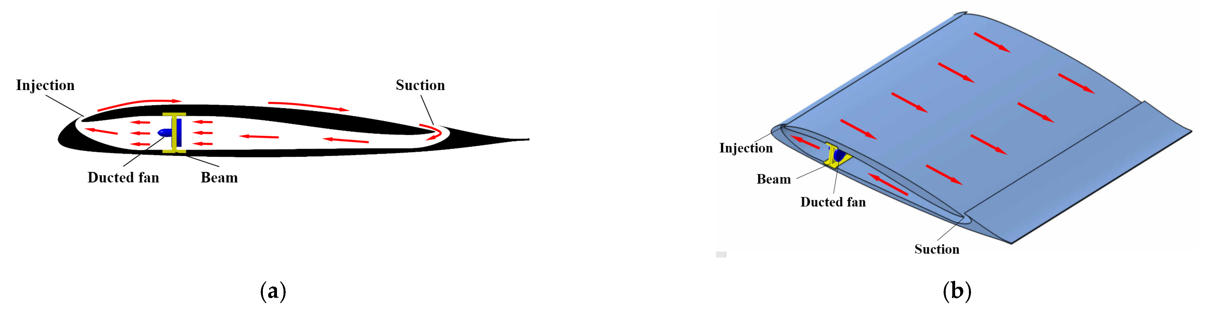
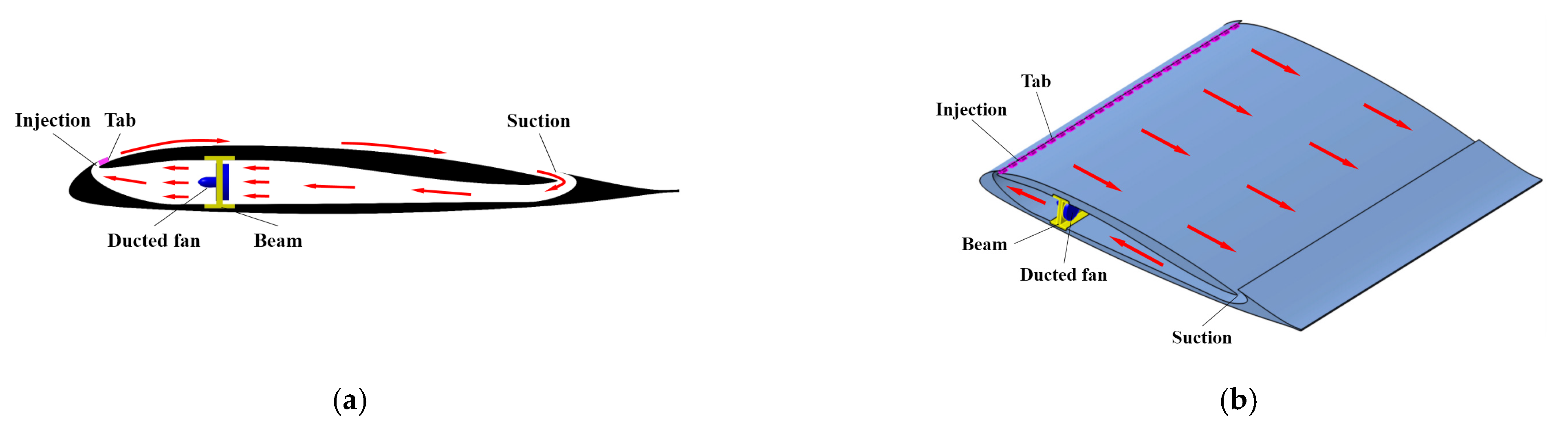
In short, DCFJ312-OF1/2 airfoil has better aerodynamic performance than CFJ312 airfoil. CFJ and DCFJ technologies transport the energy to the main flow by the turbulent mixing between the jet and main flow, thereby improving the performance of OA312 airfoil. However, only the streamwise vortex structure is generated by CFJ technology while both streamwise and spanwise vortex structures are generated by DCFJ technology because of the existence of taps. Thus, DCFJ technology is more effective in the turbulent mixing than CFJ technology, and DCFJ technology has greater performance enhancement for OA312 rotor airfoil than CFJ technology.

3.2. Effect of the Obstruction Factor

The RUL is fixed to 0.025 (the blocking unit length is 20 mm). As shown in Figure 11, the DCFJ rotor airfoils with OF = 1/3, 1/2 and 2/3, which are named DCFJ312-OF1/3, DCFJ312-OF1/2 and DCFJ312-OF2/3, respectively, are selected for this trade study.
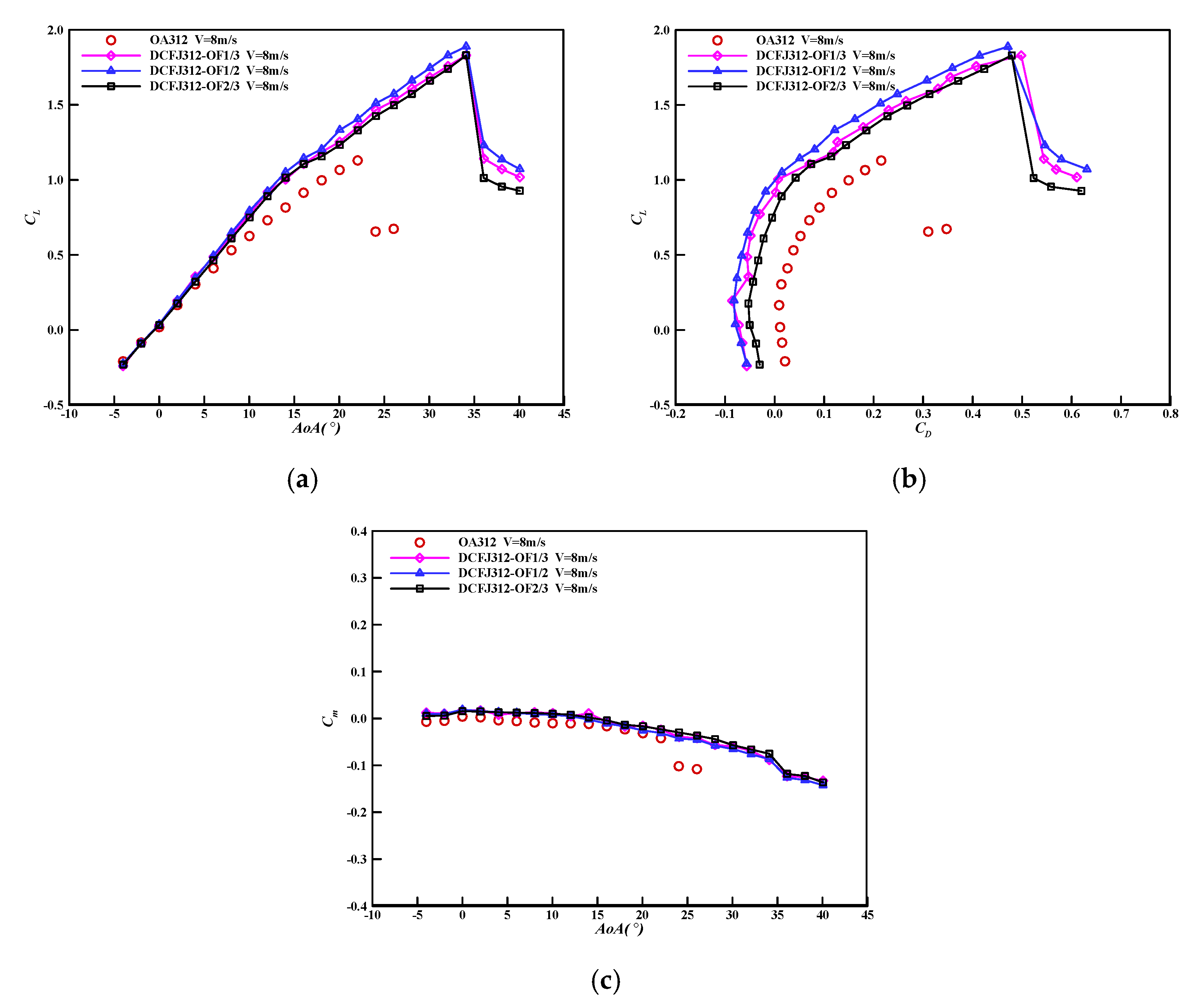
Figure 12 shows the aerodynamic coefficient comparisons of DCFJ312 airfoils with various OFs. Table 7 shows the lift coefficients of DCFJ312 airfoils with various OFs at AoA = 10° and 20°. It can be seen from Figure 12a and Table 7 that when the AoA is less than 5°, lift coefficients of DCFJ312 airfoils with various OFs are also almost equal, and slightly larger than that of the OA312 airfoil. When the AoA is greater than 5°, lift coefficients of DCFJ312 airfoils with various OFs are significantly improved in comparison with the OA312 airfoil. As the OF increases, the lift coefficient of the DCFJ312 airfoil first increases and then decreases. The DCFJ312-OF1/2 airfoil has the highest lift coefficient among the three DCFJ312 airfoils. At AoA = 10°, the lift coefficient increment of the DCFJ312-OF1/2 airfoil over the OA312 airfoil is 3.2% greater than that of the DCFJ312-OF1/3 airfoil over the OA312 airfoil, and 6.4% greater than that of the DCFJ312-OF2/3 airfoil over the OA312 airfoil. At AoA = 20°, the lift coefficient increment of the DCFJ312-OF1/2 airfoil over the OA312 airfoil is 7.6% greater than that of the DCFJ312-OF1/3 airfoil over the OA312 airfoil, and 9.5% greater than that of the DCFJ312-OF2/3 airfoil over the OA312 airfoil.
Table 8 shows the maximum lift coefficients and stall AoAs of DCFJ312 airfoils with various OFs. When compared with the OA312 airfoil, the maximum lift coefficients and stall AoAs of DCFJ312 airfoils with various OFs are significantly improved. As the OF increases, the maximum lift coefficient of the DCFJ312 airfoil first increases and then decreases. The DCFJ312-OF1/2 airfoil has the highest maximum lift coefficient among the three DCFJ312 airfoils. The maximum lift coefficient increment of the DCFJ312-OF1/2 airfoil over the OA312 airfoil is 5.4% greater than that of the other two DCFJ312 airfoils over the OA312 airfoil. The stall AoAs of the three DCFJ312 airfoils with various OFs are the same, and 12° greater than that of the OA312 airfoil.
Table 9 shows the drag coefficients and lift-to-drag ratios of DCFJ312 airfoils with various OFs at AoA = 20°. It can be seen from Figure 12b and Table 9 that when compared with the OA312 airfoil, the drag coefficients of DCFJ312 airfoils with various OFs are significantly decreased, and the drag coefficients are even decreased to negative values at low AoA. As the OF increases, the drag coefficient of the DCFJ312 airfoil first increases and then decreases. The DCFJ312-OF1/2 airfoil has the smallest drag coefficient and highest lift-to-drag ratio among the three DCFJ312 airfoils. At AoA = 20°, the drag coefficient decrement of the DCFJ312-OF1/2 airfoil over the OA312 airfoil is 3.8% greater than that of the DCFJ312-OF1/3 airfoil over the OA312 airfoil, and 12.8% greater than that of the DCFJ312-OF2/3 airfoil over the OA312 airfoil. At AoA = 20°, the lift-to-drag ratio increment of the DCFJ312-OF1/2 airfoil over the OA312 airfoil is 20.9% greater than that of the DCFJ312-OF1/3 airfoil over the OA312 airfoil, and 42.7% greater than that of the DCFJ312-OF2/3 airfoil over the OA312 airfoil.
Table 10 shows the moment coefficients of DCFJ312 airfoils with various OFs at AoA = 10° and 20°. It can be seen from Figure 12c and Table 10 that when the AoA is less than 15°, the absolute value of the moment coefficient of the DCFJ312-OF1/2 airfoil is smallest among the three DCFJ312 airfoils. As the OF increases, the absolute value of the moment coefficient of the DCFJ312 airfoil first increases and then decreases when the AoA is greater than 15°. At AoA = 10°, the absolute value of the moment coefficient of the DCFJ312-OF1/2 airfoil is decreased by 21.2% when compared with the OA312 airfoil, while that of the DCFJ312-OF1/3 airfoil is increased by 13.1% and that of the DCFJ312-OF2/3 airfoil is increased by 3.0%. At AoA = 20°, the absolute value decrement of the moment coefficient of the DCFJ312-OF1/2 airfoil over the OA312 airfoil is 30.7% smaller than that of the DCFJ312-OF1/3 airfoil over the OA312 airfoil, and 28.1% smaller than that of the DCFJ312-OF2/3 airfoil over the OA312 airfoil.
Comprehensive comparisons of the aerodynamic characteristics of the DCFJ312 airfoil with various OFs show that: as the OF increases, the effect of lift enhancement and drag reduction of the DCFJ312 airfoil first increases and then decreases. The greater the OF, the closer the two adjacent taps and the stronger the turbulent mixing caused by the spanwise vortex structures of the DCFJ airfoil. Thus, DCFJ312-OF1/2 airfoil has better aerodynamic performance than DCFJ312-OF1/3 airfoil. However, as the OF increases, more power consumptions of the ducted fans are needed to inject the air through the smaller injection slot. When OF is 2/3, the power of the ducted fans in the experiment is not enough to inject the air through the injection slot, resulting in the insufficient mass flow. Therefore, the aerodynamic performance of the DCFJ312-OF2/3 airfoil becomes worse and the aerodynamic performance of the DCFJ312-OF1/2 airfoil is the best.

3.3. Effect of the Relative Unit Length

The OF is fixed to 1/2. The DCFJ312-OF1/2 airfoil is selected as the reference to study the effect of the RUL. As shown in Figure 13, the RUL of DCFJ rotor airfoil, which is named DCFJ312-OF1/2B, is adjusted from 0.025 (the blocking unit length is 20 mm) to 0.05 (the blocking unit length is 40 mm).
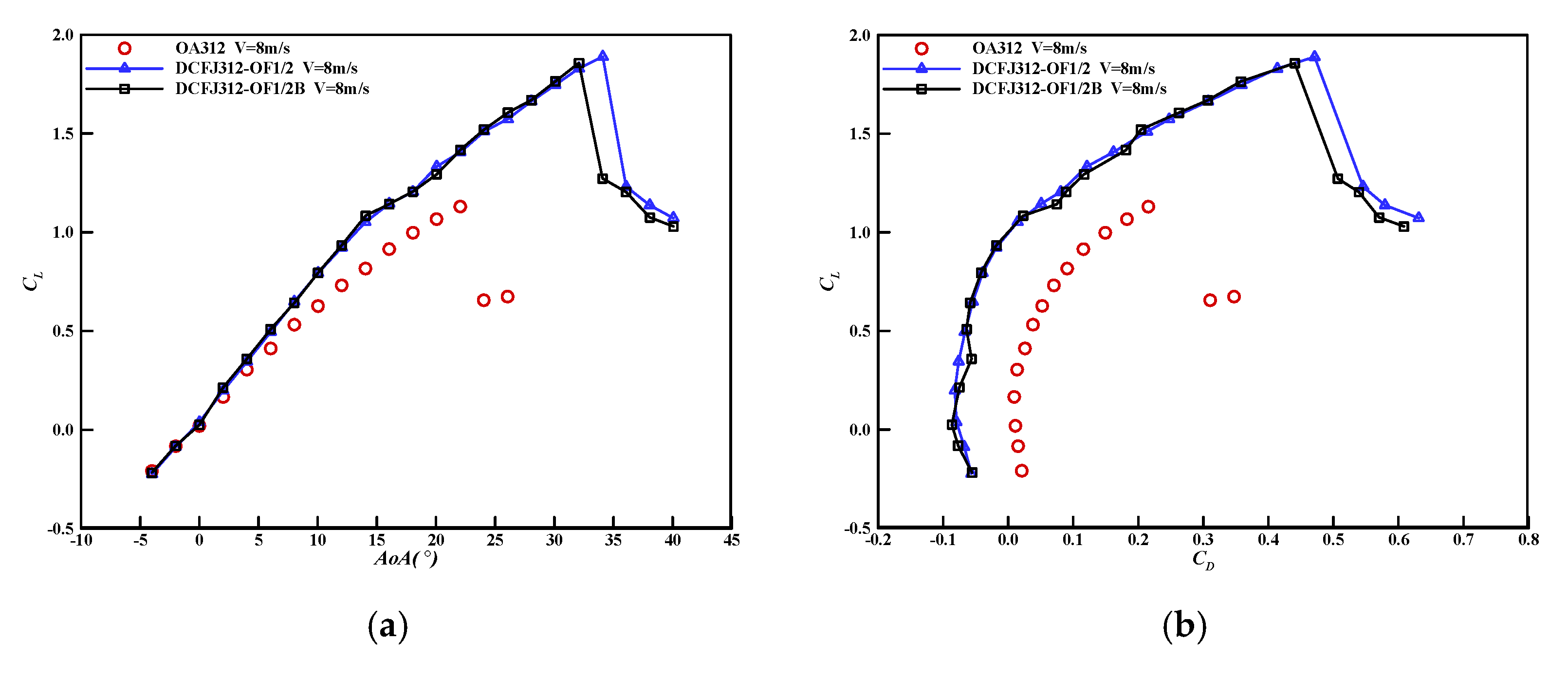
Figure 14 shows the aerodynamic coefficient comparisons of DCFJ312 airfoils with various RULs. Table 11 shows the maximum lift coefficients and stall AoAs of DCFJ312 airfoils with various RULs. It can be seen from Table 11 that the maximum lift coefficient and stall AoA of the DCFJ312-OF1/2B airfoil are smaller than that of the DCFJ312-OF1/2 airfoil. The maximum lift coefficient increment of the DCFJ312-OF1/2B airfoil over the OA312 airfoil is 2.7% smaller than that of the DCFJ312-OF1/2 airfoil over the OA312 airfoil. The stall AoA of the DCFJ312-OF1/2B airfoil is 2° smaller than that of the DCFJ312-OF1/2 airfoil. Thus, the smaller the RUL, the greater the maximum lift coefficient and stall AoA.
Table 12 shows the lift coefficients of DCFJ312 airfoils with various RULs at AoA = 10° and 20°. Table 13 shows the drag coefficients and lift-to-drag ratios of DCFJ312 airfoils with various RULs at AoA = 20°. It can be seen from Table 12 and Table 13 that the RUL has little effect on the aerodynamic characteristics of the DCFJ312 airfoil. The lift coefficients, drag coefficients and lift-to-drag ratios of DCFJ312-OF1/2 and DCFJ312-OF1/2B airfoils are almost equal at the same AoA, respectively. At AoA = 10°, the lift coefficients of DCFJ312-OF1/2 and DCFJ312-OF1/2B airfoils are both 25.4% greater than that of the OA312 airfoil. At AoA = 20°, the lift coefficient increment of the DCFJ312-OF1/2 airfoil over the OA312 airfoil is 3.8% greater than that of the DCFJ312-OF1/2B airfoil over the OA312 airfoil. The drag coefficient decrement of the DCFJ312-OF1/2 airfoil over the OA312 airfoil is 2.2% smaller than that of the DCFJ312-OF1/2B airfoil over the OA312 airfoil. The lift-to-drag ratio increment of the DCFJ312-OF1/2 airfoil over the OA312 airfoil is 0.8% smaller than that of the DCFJ312-OF1/2B airfoil over the OA312 airfoil.
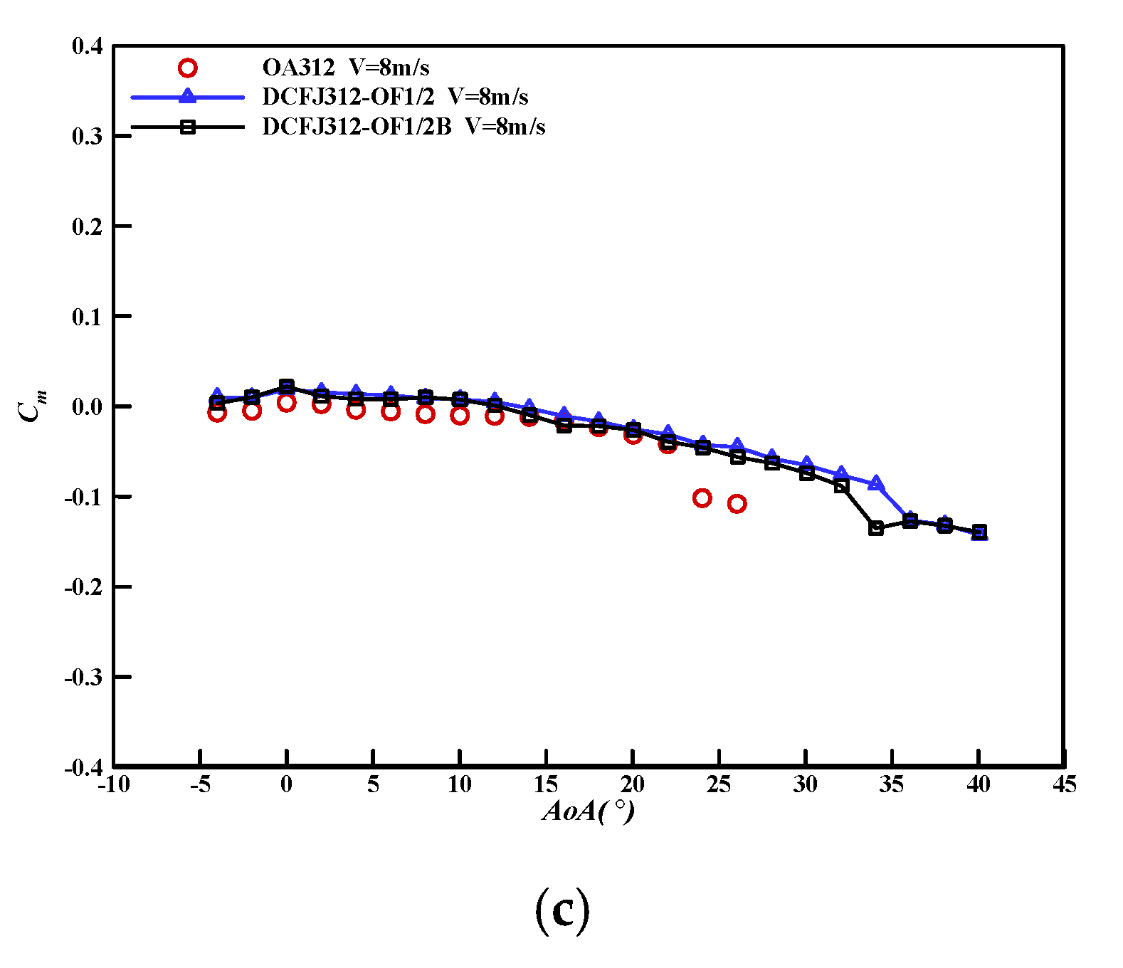
Table 14 shows the moment coefficients of DCFJ312 airfoils with various RULs at AoA = 10° and 20°. It can be seen from Table 14 that the moment coefficient of DCFJ312-OF1/2 and DCFJ312-OF1/2B airfoils are almost equal. When compared with the OA312 airfoil, the absolute values of the moment coefficients of DCFJ312 airfoils with various RULs are between 15% and 22%. At AoA = 10°, the absolute value decrement of the moment coefficient of the DCFJ312-OF1/2 airfoil over the OA312 airfoil is 2.0% smaller than that of the DCFJ312-OF1/2B airfoil over the OA312 airfoil. At AoA = 20°, the absolute value decrement of the moment coefficient of the DCFJ312-OF1/2 airfoil over the OA312 airfoil is 3.5% greater than that of the DCFJ312-OF1/2B airfoil over the OA312 airfoil.
In summary, the maximum lift coefficient and stall AoA of the DCFJ312 rotor airfoil with the smaller RUL are slightly greater than that of the DCFJ312 rotor airfoil with the larger RUL. Other aerodynamic characteristics of DCFJ312 airfoils with various RULs have little change. The reason may be that DCFJ312 airfoils with the same OF and different RULs have similar turbulent mixing effects although different spanwise vortex structures are generated.

4. Conclusions and Future Work

In this work, the flow control effects of DCFJ and CFJ technologies on the OA312 rotor airfoil are compared via wind tunnel experiments. The influence of DCFJ technology fundamental parameters on the performance enhancement of the OA312 rotor airfoil are studied. The optimal values of the fundamental parameters of the DCFJ rotor airfoil are obtained.
Both DCFJ and CFJ technologies can significantly reduce the drag coefficient, increase the maximum lift coefficient and stall AoA of the rotor airfoil. Moreover, even the negative drag is achieved at low AoA and the moment coefficient has little change. The flow control effect of DCFJ technology on rotor airfoil is demonstrated to be better than CFJ technology.
As the OF increases, the effect of lift enhancement and drag reduction of the DCFJ312 airfoil first increases and then decreases, and the aerodynamic performance of the DCFJ312 airfoil with OF = 1/2 is the best. The RUL has little effect on the aerodynamic characteristics of the DCFJ312 airfoil.
The optimal values of the fundamental parameters of the DCFJ rotor airfoil are OF = 1/2 and RUL = 0.025. In this case, the maximum lift coefficient and stall AoA are increased by 67.3% and 12°, respectively.

Future Work

In this work, the low-speed wind tunnel experiments of the rotor airfoil using DCFJ and CFJ technologies are carried out. The high-speed wind tunnel experiments of the rotor airfoil using DCFJ and CFJ technologies should be further investigated. The prototypes should be manufactured to validate the influence of DCFJ and CFJ technologies on the integrity and durability of the structure of the real rotor blade.

Author Contributions

Conceptualization, X.Y. and B.S.; methodology, S.Z., X.Y. and B.S.; validation, S.Z., Z.L. and B.W.; formal analysis, S.Z. and B.W.; investigation, S.Z. and Z.L.; resources, S.Z. and B.W.; data curation, S.Z. and Z.L.; writing—original draft preparation, S.Z.; writing—review and editing, S.Z., X.Y. and B.S.; visualization, S.Z.; supervision, X.Y. and B.S.; project administration, X.Y. and B.S.; funding acquisition, X.Y. All authors have read and agreed to the published version of the manuscript.

Funding

This research was funded by National Natural Science Foundation of China, Grant Number 11672243.

Institutional Review Board Statement

Not applicable.

Informed Consent Statement

Not applicable.

Data Availability Statement

Not applicable.

Conflicts of Interest

The authors declare no conflict of interest.

References

  1. Ariyarit, A.; Sugiura, M.; Tanable, Y.; Kanazaki, M. Hybird surrogate-model-based multi-fidelity efficient global optimization applied to helicopter blade design. Eng. Optim. 2018, 50, 1016–1040. [Google Scholar] [CrossRef]
  2. Phiboon, T.; Khankwa, K.; Petcharat, N.; Phoksombat, N.; Kanazaki, M.; Kishi, Y.; Bureerat, S.; Ariyarit, A. Experiment and computation multi-fidelity multi-objective airfoil design optimization of fixed-wing UAV. J. Mech. Sci. Technol. 2021, 35, 4065–4072. [Google Scholar] [CrossRef]
  3. Zha, G.C.; Paxton, C. A novel airfoil circulation augment flow control method using co-flow jet. In Proceeding of the 2rd AIAA Flow Control Conference, Portland, OR, USA, 28 June–1 July 2004. [Google Scholar]
  4. Zha, G.C.; Gao, W.; Paxton, C. Numerical simulation of co-flow jet airfoil flows. In Proceeding of the 44th AIAA Aerospace Sciences Meeting and Exhibit, Reno, NV, USA, 9–12 January 2006. [Google Scholar]
  5. Zha, G.C.; Gao, W.; Paxton, C. Jet effects on coflow jet airfoil performance. AIAA J. 2007, 45, 1222–1231. [Google Scholar] [CrossRef]
  6. Lefebvre, A.; Dano, B.; Bartow, W.B.; Fronzo, M.D.; Zha, G.C. Performance and energy expenditure of coflow jet airfoil with variation of Mach number. J. Aircr. 2016, 53, 1757–1767. [Google Scholar] [CrossRef] [Green Version]
  7. Liu, Z.X.; Zha, G.C. Transonic airfoil performance enhancement using co-flow jet active flow control. In Proceeding of the 8th AIAA Flow Control Conference, Washington, DC, USA, 13–17 June 2016. [Google Scholar]
  8. Boling, J.; Dhakal, S.; Yang, Y.C.; Zha, G.C. Numerical investigation of low speed performance of transonic coflow jet supercritical airfoil. In Proceeding of the 35th AIAA Applied Aerodynamics Conference, Denver, CO, USA, 5–9 June 2017. [Google Scholar]
  9. Xu, J.H.; Li, K.; Song, W.P.; Yang, X.D. Influence of co-flow jet parameters on airfoil aerodynamic performance at low Reynolds number. Acta Aeronaut. Astronaut. Sin. 2018, 39, 122018. [Google Scholar]
  10. Xu, H.Y.; Xing, S.L.; Ye, Z.Y. Numerical study of the S809 airfoil aerodynamic performance using a co-flow jet active control concept. J. Renew. Sustain. Energy 2015, 7, 1–20. [Google Scholar] [CrossRef]
  11. Xu, H.Y.; Qiao, C.L.; Ye, Z.Y. Dynamic stall control on the wind turbine airfoil via a co-flow jet. Energies 2016, 9, 429. [Google Scholar] [CrossRef] [Green Version]
  12. Xu, K.W.; Zha, G.C. Investigation of coflow jet active flow control for wind turbine airfoil. In Proceeding of the AIAA Aviation 2020 Forum, Virtual Event, 15–19 June 2020. [Google Scholar]
  13. Sun, X.J.; Xu, Y.Q.; Huang, D.G. Numerical simulation and research on improving aerodynamic performance of vertical axis wind turbine by co-flow jet. J. Renew. Sustain. Energy 2019, 11, 013303. [Google Scholar] [CrossRef]
  14. Yang, Y.C.; Zha, G.C. Super-lift coefficient of active flow control airfoil: What is the limit? In Proceeding of the 55th AIAA Aerospace Sciences Meeting, Grapevine, TX, USA,, 9–13 January 2017. [Google Scholar]
  15. Zha, G.C.; Yang, Y.C.; Ren, Y.; McBreen, B. Super-lift and thrusting airfoil of coflow jet actuated by micro-compressors. In Proceeding of 2018 Flow Control Conference, Atlanta, GA, USA, 25–29 June 2018. [Google Scholar]
  16. Wang, Y.; Yang, Y.C.; Zha, G.C. Study of super-lift coefficient of co-flow jet airfoil and its power consumption. In Proceeding of the AIAA Aviation 2019 Forum, Dallas, TX, USA, 17–21 June 2019. [Google Scholar]
  17. Zha, G.C.; Ren, Y.; Gan, J.; Espinal, D. A high efficiency low noise VTOL/ESTOL concept using coflow jet airfoil. In Proceeding of the AIAA Propulsion and Energy 2019 Forum, Indianapolis, IN, USA, 19–22 August 2019. [Google Scholar]
  18. Boling, J.; Ren, Y.; Zha, G.C. A high-speed high-efficiency VTOL vehicle using coflow jet flow control. In Proceeding of the AIAA Aviation 2020 Forum, Virtual Event, 15–19 June 2020. [Google Scholar]
  19. Dano, B.P.E.; Zha, G.C.; Castillo, M. Experimental study of co-flow jet airfoil performance enhancement using discrete jets. In Proceedings of the 49th AIAA Aerospace Sciences Meeting including the New Horizons Forum and Aerospace Exposition, Orlando, FL, USA, 4–7 January 2011. [Google Scholar]
  20. Dano, B.P.E.; Lefebvre, A.; Zha, G.C. Mixing mechanism of a discrete co-flow jet airfoil. In Proceedings of the 41st AIAA Fluid Dynamics Conference and Exhibit, Honolulu, HI, USA, 27–30 June 2011. [Google Scholar]
  21. Song, C.; Yang, X.D.; Zhu, M.; Song, W.P. Investigating lift increase and drag reduction for airfoils using discrete CFJ (co-flow jet). J. Northwest. Polytech. Univ. 2015, 33, 191–196. [Google Scholar]
  22. Zhang, S.L.; Yang, X.D.; Song, B.F.; Xu, J.H. Numerical and experimental study of the co-flow jet airfoil performance enhancement. In Proceeding of the 55th AIAA Aerospace Sciences Meeting, Grapevine, TX, USA, 9–13 January 2017. [Google Scholar]
  23. Zhang, S.L.; Yang, X.D.; Song, B.F.; Wang, B.; Li, Z.Y. Experimental investigation of lift enhancement and drag reduction of rotor airfoil using co-flow jet concept. Adv. Aeronaut. Sci. Eng. 2021, 12, 44–51. [Google Scholar]
Figure 1. Schematic diagrams of CFJ principle. (a) Front view; (b) isometric view.
Applsci 11 09561 g001
Figure 2. Schematic diagrams of DCFJ principle. (a) Front view; (b) isometric view.
Applsci 11 09561 g002
Figure 3. DCFJ312 airfoil model.
Applsci 11 09561 g003
Figure 4. Interior of DCFJ312 airfoil model.
Applsci 11 09561 g004
Figure 5. Taps of DCFJ312 airfoil model.
Applsci 11 09561 g005
Figure 6. Airfoil model installed in the 4 m × 3 m wind tunnel.
Applsci 11 09561 g006
Figure 7. (a) Ducted fan; (b) switching power supply.
Applsci 11 09561 g007
Figure 8. (a) Watt meter; (b) electrical tunable.
Applsci 11 09561 g008
Figure 9. Schematic representation of injection of DCFJ airfoil.
Applsci 11 09561 g009
Figure 10. Aerodynamic coefficients comparisons of DCFJ312 and CFJ312 airfoils. (a) Lift coefficient; (b) lift-to-drag ratio; (c) moment coefficient.
Applsci 11 09561 g010
Figure 11. Injections of DCFJ312 airfoils with various OFs (a) OF = 1/3; (b) OF = 1/2; (c) OF = 2/3.
Applsci 11 09561 g011
Figure 12. Aerodynamic coefficients comparisons of DCFJ312 airfoils with various OFs. (a) Lift coefficient; (b) lift-to-drag ratio; (c) moment coefficient.
Applsci 11 09561 g012
Figure 13. Injections of DCFJ312 airfoils with various RULs. (a) RUL = 0.025; (b) RUL = 0.05.
Applsci 11 09561 g013
Figure 14. Aerodynamic coefficients comparisons of DCFJ312 airfoils with various RULs. (a) Lift coefficient; (b) lift-to-drag ratio; (c) moment coefficient.
Applsci 11 09561 g014aApplsci 11 09561 g014b
Table 1. Detailed parameters of DCFJ312 and CFJ312 airfoils.
ParametersValues
Chord length0.8 m
Spanwise length1.6 m
Injection slot height0.63% (5 mm) of the chord length
Location of the injection slot5% of the chord
Suction slot height1.25% (10 mm) of the chord length
Location of the suction slot80% of the chord
Location of the ducted fan40% of the chord
Table 2. Calibration and validation of the wind tunnel measuring system.
Loading Values of Standard Weight (kg)Measurement Values of X Direction (kg)Measurement Values of Y Direction (kg)Measurement Values of Z Direction (kg)
00.0100.0030.002
54.9565.0484.963
109.91610.0949.913
1514.88915.12214.892
109.94710.0699.932
55.0105.0335.024
00.0080.0100.005
Table 3. Comparisons of lift coefficients of DCFJ312 and CFJ312 airfoils at typical AoAs.
AirfoilsCLCL
AoA = 10°AoA = 20°AoA = 10°AoA = 20°
OA3120.631.06
CFJ3120.781.2723.8%19.8%
DCFJ312-OF1/20.791.3325.4%25.5%
Table 4. Comparisons of maximum lift coefficients and stall AoAs of DCFJ312 and CFJ312 airfoils.
AirfoilsCLmaxCLmaxAoAstallAoAstall
OA3121.1322°
CFJ3121.7655.8%32°10°
DCFJ312-OF1/21.8967.3%34°12°
Table 5. Comparisons of drag coefficients and lift-to-drag ratios of DCFJ312 and CFJ312 airfoils at AoA = 20°.
AirfoilsCDCDL/DL/D
OA3120.18195.83
CFJ3120.1286−29.3%9.8869.5%
DCFJ312-OF1/20.1201−34.0%11.0789.9%
Table 6. Comparisons of moment coefficients of DCFJ312 and CFJ312 airfoils at typical AoAs.
AirfoilsCM△|CM|
AoA = 10°AoA = 20°AoA = 10°AoA = 20°
OA312−0.0099−0.0310
CFJ3120.0116−0.025717.2%−17.1%
DCFJ312-OF1/20.0078−0.0251−21.2%−19.0%
Table 7. Comparisons of lift coefficients of DCFJ312 airfoils with various OFs at typical AoAs.
AirfoilsCLCL
AoA = 10°AoA = 20°AoA = 10°AoA = 20°
OA3120.631.06
DCFJ312-OF1/30.771.2522.2%17.9%
DCFJ312-OF1/20.791.3325.4%25.5%
DCFJ312-OF2/30.751.2319.0%16.0%
Table 8. Comparisons of maximum lift coefficients and stall AoAs of DCFJ312 airfoils with various OFs.
AirfoilsCLmaxCLmaxAoAstallAoAstall
OA3121.1322°
DCFJ312-OF1/31.8361.9%34°12°
DCFJ312-OF1/21.8967.3%34°12°
DCFJ312-OF2/31.8361.9%34°12°
Table 9. Comparisons of drag coefficients and lift-to-drag ratios of DCFJ312 airfoils with various OFs at AoA = 20°.
AirfoilsCDCDL/DL/D
OA3120.18195.83
DCFJ312-OF1/30.1269−30.2%9.8569.0%
DCFJ312-OF1/20.1201−34.0%11.0789.9%
DCFJ312-OF2/30.1434−21.2%8.5847.2%
Table 10. Comparisons of moment coefficients of DCFJ312 airfoils with various OFs at typical AoAs.
AirfoilsCM△|CM|
AoA = 10°AoA = 20°AoA = 10°AoA = 20°
OA312−0.0099−0.0310
DCFJ312-OF1/30.0112−0.015613.1%−49.7%
DCFJ312-OF1/20.0078−0.0251−21.2%−19.0%
DCFJ312-OF2/30.0102−0.01643.0%−47.1%
Table 11. Comparisons of maximum lift coefficients and stall AoAs of DCFJ312 airfoils with various RULs.
AirfoilsCLmaxCLmaxAoAstallAoAstall
OA3121.1322°
DCFJ312-OF1/21.8967.3%34°12°
DCFJ312-OF1/2B1.8664.6%32°10°
Table 12. Comparisons of lift coefficients of DCFJ312 airfoils with various RULs at typical AoAs.
AirfoilsCLCL
AoA = 10°AoA = 20°AoA = 10°AoA = 20°
OA3120.631.06
DCFJ312-OF1/20.791.3325.4%25.5%
DCFJ312-OF1/2B0.791.2925.4%21.7%
Table 13. Comparisons of drag coefficients and lift-to-drag ratios of DCFJ312 airfoils with various RULs at AoA = 20°.
AirfoilsCDCDL/DL/D
OA3120.18195.83
DCFJ312-OF1/20.1201−34.0%11.0789.9%
DCFJ312-OF1/2B0.1160−36.2%11.1290.7%
Table 14. Comparisons of moment coefficients of DCFJ312 airfoils with various RULs at typical AoAs.
AirfoilsCM△|CM|
AoA = 10°AoA = 20°AoA = 10°AoA = 20°
OA312−0.0099−0.0310
DCFJ312-OF1/20.0078−0.0251−21.2%−19.0%
DCFJ312-OF1/2B0.0076−0.0262−23.2%−15.5%
Publisher’s Note: MDPI stays neutral with regard to jurisdictional claims in published maps and institutional affiliations.

