1. Introduction
Cable-driven parallel robots (
CDPRs in short) combine the successful features of parallel manipulators with the benefits of cable transmissions. The payload is divided among light extendable cables, resulting in an energy-efficient system that can achieve high acceleration of the end-effector (
EE) over a remarkably large workspace. From a structural point of view, a
CDPR is formed by a set of actuation units, usually fixed to a frame, and a mobile platform, working as
EE [
1]. The cables, driven by the actuation units, are guided inside the robot workspace (
WS) using a guidance system, and then connected to the mobile platform. The variation of cable lengths is responsible for the
EE displacement throughout the robot
WS. These features result in easily reconfigurable systems, where the
WS can be modified by relocating the actuation and/or guidance units [
2].
Nevertheless, the use of
CDPRs in industrial environments is still limited, mainly due to the drawbacks of employing flexible cables. Indeed, cables impose unilateral constraints that can only exert tensile forces and, consequently, the
EE cannot withstand any arbitrary external action. In addition, the viscoelastic nature of cables can cause their elongation under prolonged load application [
3]. This highly non-linear behavior complicates the control of the robot and the estimation of the actual cable lengths, and therefore the determination of the platform pose through direct kinematics. To enhance the robot controllability,
CDPRs can be overconstrained by employing a number of cables higher than the degrees of freedom (
DoFs) of the
EE. This allows cables to pull one against the other and to keep the overall system controllable over a wide range of externally applied loads. In other cases, to increase accessibility and reduce hardware complexity, suspended architectures with less cables than
EE DoFs can be used, though they are more difficult to control [
4,
5].
Thanks to their simple architecture, high reconfigurability, easy deployability, and large workspace,
CDPRs have been proposed in many fields of application: entertainment [
6,
7], logistics [
8], construction [
9,
10,
11], maintenance [
12,
13], to name a few. In general, it is possible to design a general-purpose machine that can be dedicated to different tasks by changing the
EE tool [
14,
15] or, in alternative, a
CDPR for a specific purpose can be developed. In the second case, the robot geometry, the number and configuration of cables, and, consequently, additional design constraints are established by the final task. This is the case of the deployable
CDPR in [
16]: the suspended architecture and the
EE self-deployability ensure the high orientational capability required for the laser scanning of low-accessibility environments. As an additional example, the storage-retrieval
CDPR in [
8] is equipped with eight cables, despite the planar nature of the robot task, in order to provide a suitable machine stiffness and prevent platform tilt.
Usually, if the task requires a specific motion pattern of the
EE, it is possible to act in two different ways to limit the
EE range of motion. First, an external means, which physically constrains the
EE, can be employed. This happens with the
CDPR Pickable [
17], whose
EE is constrained to slide on a planar surface thanks to an air-bearing system. Likewise, in [
13], the
EE of the robot moves in direct contact with the building façade to perform window cleaning operations. The contact of the
EE with the environment requires specific contact models [
18], and suitable force-control strategies [
19]. For the Pickable robot, undesired phenomena, such as friction, are significantly reduced by using air bearings, whereas, for the cleaning robot, friction is part of the process itself. A different approach for constraining the
EE motion consists in adopting special cable configurations, such as the parallelogram arrangements inspired by delta robots [
20,
21,
22]. This expedient allows obtaining a translational motion of the
EE without any external constraint, provided that all cables are taut. This is useful in the case of large-scale industrial tasks, such as pick-and-place and warehousing [
23], or operations that need deployable systems, such as rescue and contour crafting [
24,
25].
The parallelogram arrangement strategy can also be applied in non-contact tasks where the
EE must move on a prescribed vertical plane without interacting with the surrounding environment. This is the case of welding, laser engraving, thermal treatment, and decoration or inspection of building façades, to name a few. This paper focuses on the design of a
CDPR for this kind of applications. Specifically, an overconstrained planar machine is presented. This prototype employs a parallelogram cable arrangement to constrain the
EE to move on a vertical plane. Four cables, closed in a parallelogram loop, are used to control the mobile platform’s three degrees of freedom (
DoFs). The cable guidance system comprises a pair of swivel pulleys whose swivel axes are orthogonal to the work surface: the intersections of these swivel axes with the work surface effectively define the cable proximal and distal points. Each cable loop is driven by one winch, whose drum has two helicoidal starts. Each winch includes a rotary encoder for cable length control. In addition, the pulley swivel axes are equipped with rotary encoders to achieve redundant kinematic measures, and cable tensions are measured with shear beam load cells integrated into the proximal anchor systems. Like other planar
CDPR that share the idea of parallelogram mechanisms [
23,
26], this system allows the platform to move on a defined plane, excluding low-amplitude oscillatory motions induced by external disturbances [
27,
28]. On the other hand, unlike the others, the proposed system shows three advantages: the use of a single cable loop, instead of two separate cables, ensures that the parallel cable segments are in tension when controlled by a single actuator, thus reducing the number of actuators to be used; the cable anchor system includes a measurement unit to continuously monitor cable tensions and cable angles with respect to the frame; the mounting arrangement of the swivel pulleys allows to estimate the cable lengths as distances between two precisely defined points, which are the intersections between the swivel axes and the work plane, without introducing geometrical approximations. Consequently, a simple geometric model can be adopted to control the
CDPR without inherent geometrical errors.
The paper is organized as follows. The main aspects to be taken into consideration for the mechanical design of a
CDPR are described in
Section 2. Then, the design of the planar overconstrained
CDPR prototype is presented in
Section 3, focusing on the actuation and guidance system, and the influence of the kinematic model. In
Section 4, as an application example, an experiment of the robot performing laser engraving is reported and discussed. Lastly, some conclusions are drawn.
2. Design Strategies
In most cases, cables are driven by actuators that are placed on a fixed base. Sometimes, if deployability is a requirement, they can be attached to mobile vehicles [
24] or placed on the mobile platform [
29]. A guidance system is used to convey cables from the actuators to the mobile platform. Many authors analyzed the design process of
CDPRs and identified several methods for optimizing their structure and dimensions [
1,
30]. For a given criterion (i.e., workspace dimension, accuracy, stiffness, orientation capability), optimization procedures help determine the geometry of the
CDPR, including the number of cables, position of cable anchor points, and platform and frame shapes [
2,
15,
31]. Once the architecture is known, the hardware design requires developing three distinct systems: the actuation unit, the guidance system, and the mobile platform. These systems can be equipped with suitable sensors, to monitor the robot performance and obtain feedback on relevant control variables. The two most notable examples are cable lengths, which are usually estimated by using angular sensors mounted on the actuation unit motors, and cable tensions, whose measurement involves integrating force sensors in the actuation unit, guidance system, or
EE [
1].
This section shows how specific design techniques can help keep the robot model and control as simple as possible without introducing geometrical approximations. Usually, a simplified kinematic model, called standard in the following, is adopted. This model considers cables inextensible and massless and, thus, treated as line segments between two points, one on the mobile platform and the other on the frame (distal and proximal anchor points, respectively). The former is usually assumed to be fixed with respect to the moving platform, whereas the latter is fixed with respect to the robot frame. These assumptions neglect not only all effects caused by the elastic nature of cables, which may be negligible in some small-to-medium-scale applications, but also the kinematics of the guidance system. Geometrical-model errors can be limited by accounting for the pulley geometry [
4,
32], but the model and control complexity is usually increased. As an alternative, if the standard kinematic model is to be used without inherent geometrical errors, special design techniques of the actuation units and guidance systems can be used, as discussed in the following.
2.1. Actuation Unit
The most appropriate type of actuation is chosen depending on the
EE motion pattern and
WS size, defined by the task [
1,
33]. A rotary actuation system generally consists of a servo-actuated winch where the cable is coiled onto a cylindrical drum. This solution is easy to implement but can result in low robot position accuracy since it introduces several errors when estimating cable lengths [
34]. Lengths are computed by measuring the rotation of the motor and, thus, they depend on the drum design and cable arrangement on it. Linear actuation systems reduce cable-length estimation errors, but they usually limit the size of the achievable
WS [
35], or increase cable wear [
34].
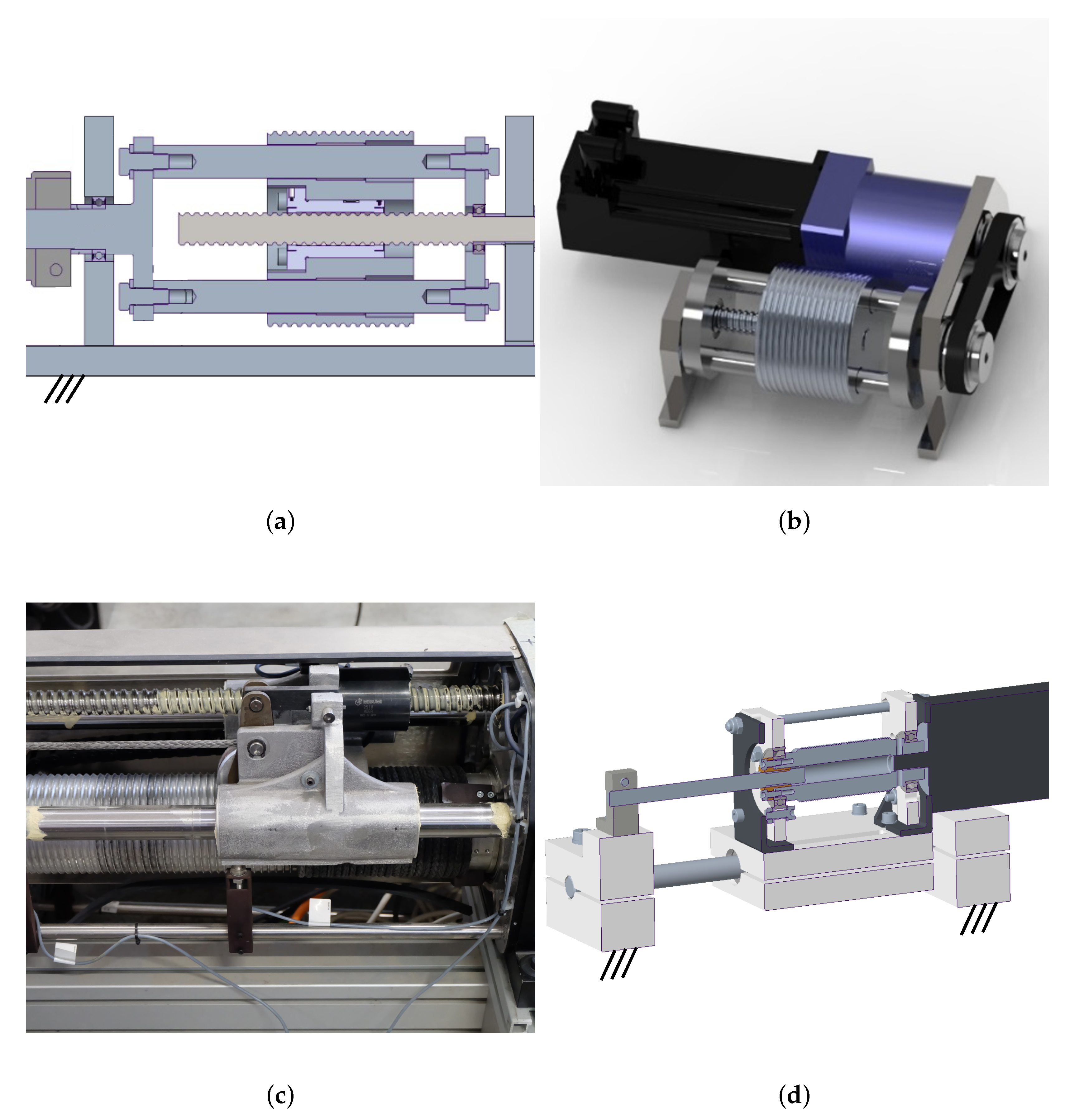
A solution could be to adopt a rotary actuation system designed to be as close as possible to the model intended for its control. The main drawback of the rotary actuation, if a simple lifting winch is considered, is the fact that the cable exit direction from the drum varies, even unpredictably, as the motor rotates: this results in a non-linear transmission ratio between the motor angle and the cable length, which is usually undesirable. A constant transmission ratio can be obtained (i) by avoiding the cable overlapping onto the drum surface, (ii) by suitably grooving the drum to accommodate the cable, which is also desirable for reducing cable wear [
36], and (iii) by constraining the cable to exit the drum in a fixed, known, direction. There are several solutions in the literature to achieve such desired design requirements (
Figure 1).
It is possible to rototranslate the drum [
16,
37,
38] so that the cable exit point from the drum, and consequently its direction, is kept fixed with respect to the winch frame, while the cable is coiled and uncoiled. This is usually achieved by employing screw/nut joints to convert the rotational motion of the motor into rotational and translational motion of the drum, and allowing the drum to translate by mounting it on a passive prismatic joint. In [
38] the drum houses a nut and two pairs of cylindrical bearings. Two rods, which are coupled with the motor shaft, parallel to the drum axis, but mounted with a radial offset with respect to the drum, pass through the bearings, thus transmitting the rotational motion, but allowing the drum to translate. The translation is caused by the drum nut being joined with a screw, which is fixed on the winch frame: a cross section of the drum system is shown in
Figure 1a. The main advantages of this solution are compactness and mechanical simplicity, but this design suffers from one main drawback, namely the rods used for transmitting the motor rotations pass through the drum, thus the latter diameter needs to be large. An example of this design is shown in
Figure 1b, where a timing belt is used to transmit motion from the motor to the drum, as in [
37].
As an alternative, in [
14] an auxiliary cable guiding device equipped with a pulley (
spooling helper) continuously follows the variable cable exit point on the rotating drum (
Figure 1c) by translating parallel to the drum axis, to ensure that the direction of the cable connecting the drum and the spooling helper is constant. The spooling helper is mounted on a support equipped with a nut and a pair of bearings, and thus slides with respect to fixed rods, driven by a screw, which is ultimately connected to the drum with a synchronous belt. Given its footprint, this solution has the primary benefit of allowing very long cables to be stored onto the drum. Still, an additional mechanical transmission, such as a timing belt, is always required to transmit drum motion to the screw.
A different solution allows the translation of the entire motor-drum system on a linear guide [
39], similar to the design shown in
Figure 1d. This solution has the advantage of being particularly simple and cheap, since the drum is directly connected to the motor, and the drum supports are connected to a carriage. Still, the motor mass, which needs to be translated, may limit the system’s dynamic performance.
2.2. Guidance System
One of the main advantages of
CDPRs is the possibility to locate the actuation units almost anywhere. This is possible thanks to the cable guidance system that conveys the cable, from the actuator, through the prescribed anchor points on the frame (proximal) to the anchor point on the platform (distal). For the standard model to be respected, without introducing geometrical-model errors, the cable anchor points need to be geometrically determined. An extensive review of possible construction solutions is reported in [
1], where a distinction is made between the proximal and distal anchor systems.
The mechanical devices that compose the proximal guidance system should allow for large deflection angles and at the same time determine the anchor point position. Swivel (or panning) pulleys and eyelets are primarily used for this purpose. Eyelets allow for the approximate definition of a point and significant cable orientation, but cause high cable wear [
40]. However, they are employed in many
CDPRs thanks to their simplicity, and the possibly low geometrical error introduced, if the
CDPR workspace is large [
16,
38,
41].
Figure 2 shows the use of eyelets as proximal anchor points on the fixed frame of the
CDPR prototype presented in [
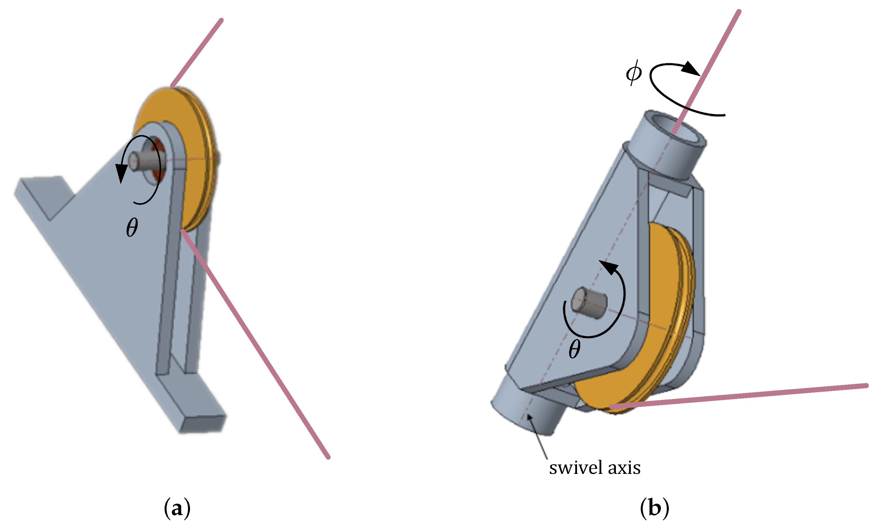
16]. Conversely, swivel pulleys can reduce cable wear and still allow for orientation in a broad direction range, since, unlike classical fixed pulleys (
Figure 3a), they can rotate about an axis tangent to the pulley groove, the swivel axis (
Figure 3b). This kind of solution is adopted in [
39,
42], and an example of exit point layout is shown in
Figure 4. In general, the presence of pulleys in the guidance system makes the system reliable, but complicates the geometrical model of the robot. This issue can be faced in two ways: by adopting a more complex model, which includes pulley kinematics for
CDPR control [
4,
32,
43], or by ignoring the actual geometry of the system, and accepting several modeling errors. Otherwise, particular layout and orientations of the pulley system must be adopted.
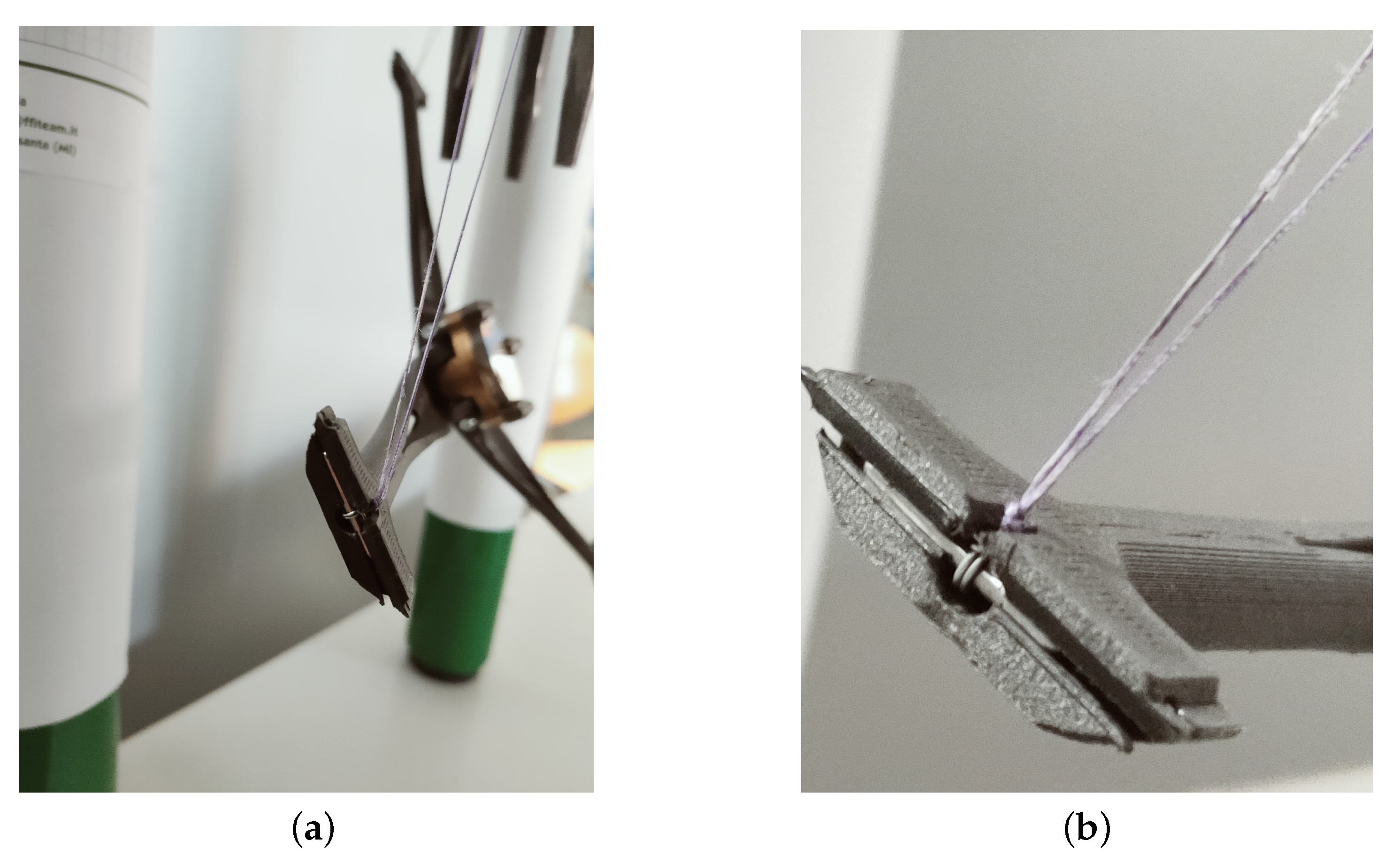
On the platform, at the distal anchor points, cables can be knotted to a fixture (i.e., an eyelet or a hook) or anchored to a universal joint: both these options allow to define a fixed point with respect to the platform. The knot solution is preferred for its simplicity (
Figure 5) [
16,
44], but it is neither accurate nor reliable for long-term use. On the other hand, the universal joint (
Figure 6) is more precise but complex and more expensive. Pulleys can also be employed if the cable needs to be deflected and not fixed at the distal anchor point. In [
45], a pulley system is used at the distal anchor point on the platform to compensate for the effect of the proximal swiveling pulley geometrical model.
3. Mechanical Design
The prototype presented in this section is devoted to non-contact tasks, such as laser engraving, welding, thermal treatment, decoration, and inspection of vertical surfaces, such as building façades. Thus, the main design requirements are the following: (i) it should present a planar vertical workspace, which should be easily scaled upon the redefinition of the installation locations of the guidance systems, (ii) the tool mounted on the platform should be interchangeable.
The 3D model of the designed prototype is shown in
Figure 7. The machine frame (1) is formed by aluminum profiles that define the robot installation (and
WS) limits. An actuation (2) and a proximal guidance unit (3) are placed at each of the four corners of the frame to coil and uncoil four cables and convey them to the distal guidance unit (4) attached to the mobile platform (5). The platform has
DoFs in the plane, thus, a 4-cable architecture results in an overconstrained manipulator. The constraint redundancy allows firstly to obtain a wider
WS and then improve the
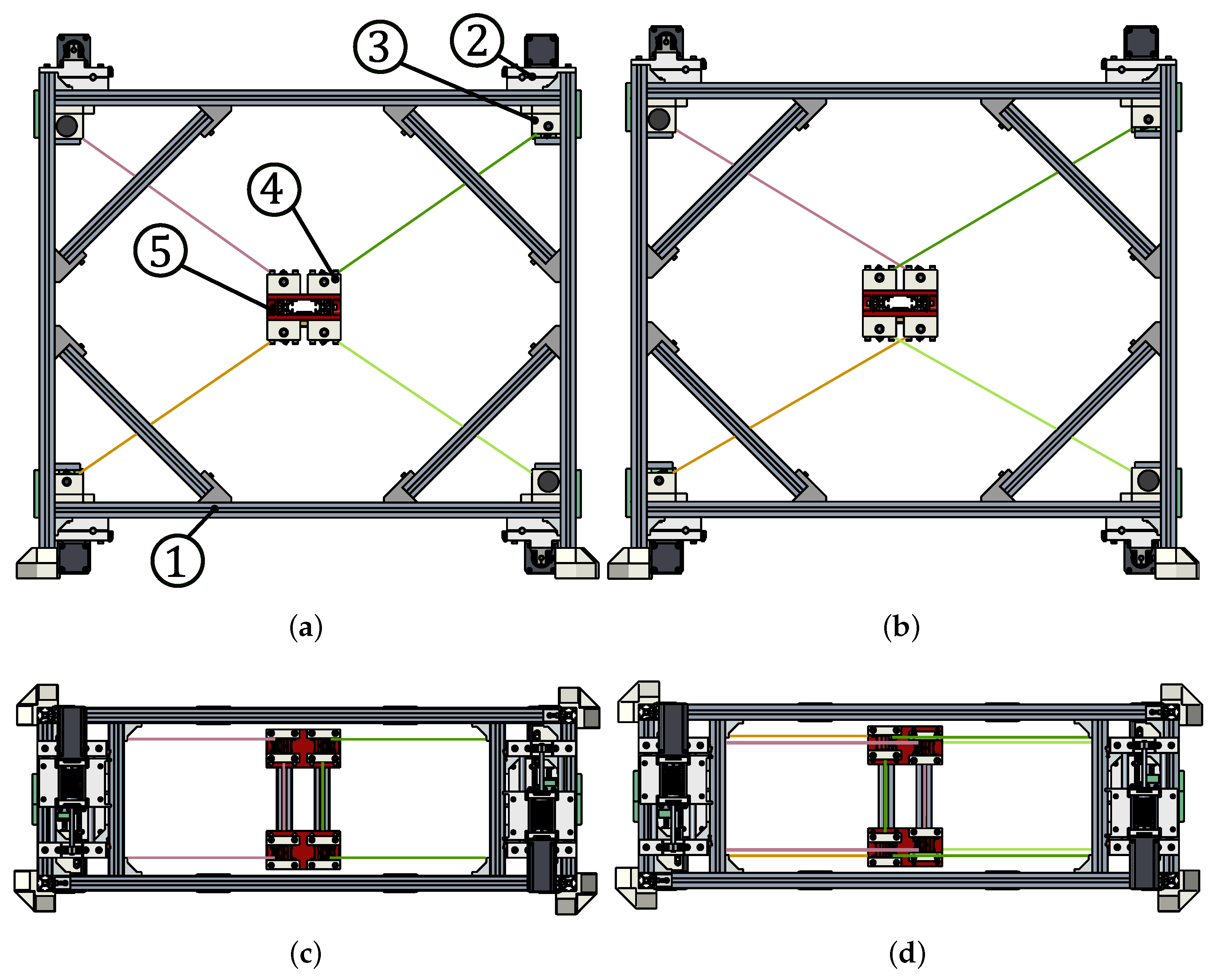
EE controllability. Redundant actuated cables make them pull one against the other to keep the overall system under tension. Reconfigurable anchor points also characterize the prototype: cables can be arranged in a standard (
Figure 8a) or crossed (
Figure 8b) layout by simply un-mounting and re-mounting the distal guidance unit. As shown in
Figure 8, each swivel pulley (1) on the platform, which forms the distal anchor point, can be translated into slots (2) on the support (3); the equivalent operation can be done on the proximal anchor systems on the frame. The crossed layout aims to improve the platform’s orientation capability [
46], if required by the task, and to withstand external torques induced by gravity (if the tool is not mounted in a barycentric position) or external disturbances.
The actuation units and guidance systems are the same for each cable, and they are described in the following subsections.
3.1. Actuation Unit
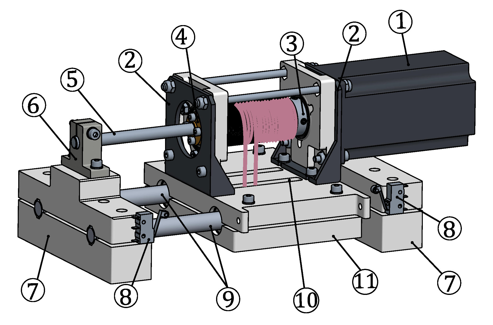
The cable actuation unit is a servo-actuated winch where both the motor and the drum translate along a linear guide during the motor rotation (
Figure 9). As described in
Section 2.1, this design choice limits the overall machine cost, at the price of poorer actuator dynamic performances: given the quasi-static requirement for the robot operation, this design choice was deemed the best. In addition, to further limit the robot cost, most components were produced by Fused Deposition Modeling (FDM) technology using PETG as base material. The choice of a rotary actuation, instead of a linear one, is supported by the project requirements reported in
Section 3. In particular a rotary actuator allows for easy scalability in case of wide-workspace applications and field deployability.
A double-helicoidal-groove aluminum drum (3) is rigidly connected to the shaft of a Wantai (57HBM20-1000, 2.1 Nm holding torque) Nema 23 servo-stepper motor (1) equipped with an incremental encoder (≈0.1 resolution). Drum dimensions were chosen in order to coil 2.2 m of a 0.51 mm diameter dyneema cable (DAIWA j-braid X8, 550 N breaking tension), and limit (for the given motor) the realizable maximum tension to 160 N (cable tension safety factor of ≈3.5). Thus, drum diameter was selected as 27 mm, and groove pitch as 2 mm. A brass nut (4) is rigidly centered to the drum and coupled to a trapezoidal screw shaft (5), which is clamped at one end to the actuation unit frame, in a support element (6). While the motor rotates, the drum-motor system, fixed to a carriage (11) using two brackets (2), moves on a linear guide (9) made by two circular rods and linear ball bearings. The drum and the shaft have the same pitch, so the cable portions exiting the drum always have a fixed direction and position with respect to the winch frame. Two end-stop switches (8) are mounted at the physical limits of the drum-motor system, to provide a safety-stop signal to the motor controller. The winch frame is ultimately fixed to the overall robot frame with bolted connections via two plates (7).
This winch houses one of the four cables. One end of the cable is fixed to the drum employing a screw. Then, the cable is coiled onto the first start of the drum and conveyed to the guidance system through a thin slot (10) on the carriage (11). After being guided to the distal anchor point on the platform (as detailed in
Section 3.2), the cable returns to the drum through the slot (10) and is then wound onto the other start of the drum and secured with another screw.
3.2. Guidance System
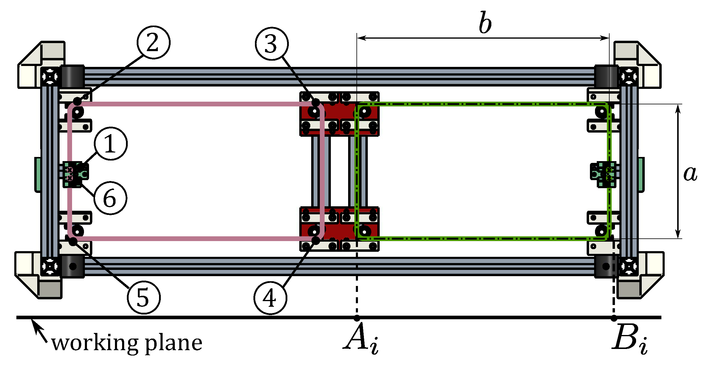
The cable guidance system is designed to (i) guide each of the four cables on a parallelogram-like routing (
Figure 10) to ensure the motion of the
EE in a defined plane; (ii) geometrically define the cable exit points, to apply a standard kinematic model for robot control, (iii) integrate a load sensor for cable tension measurement.
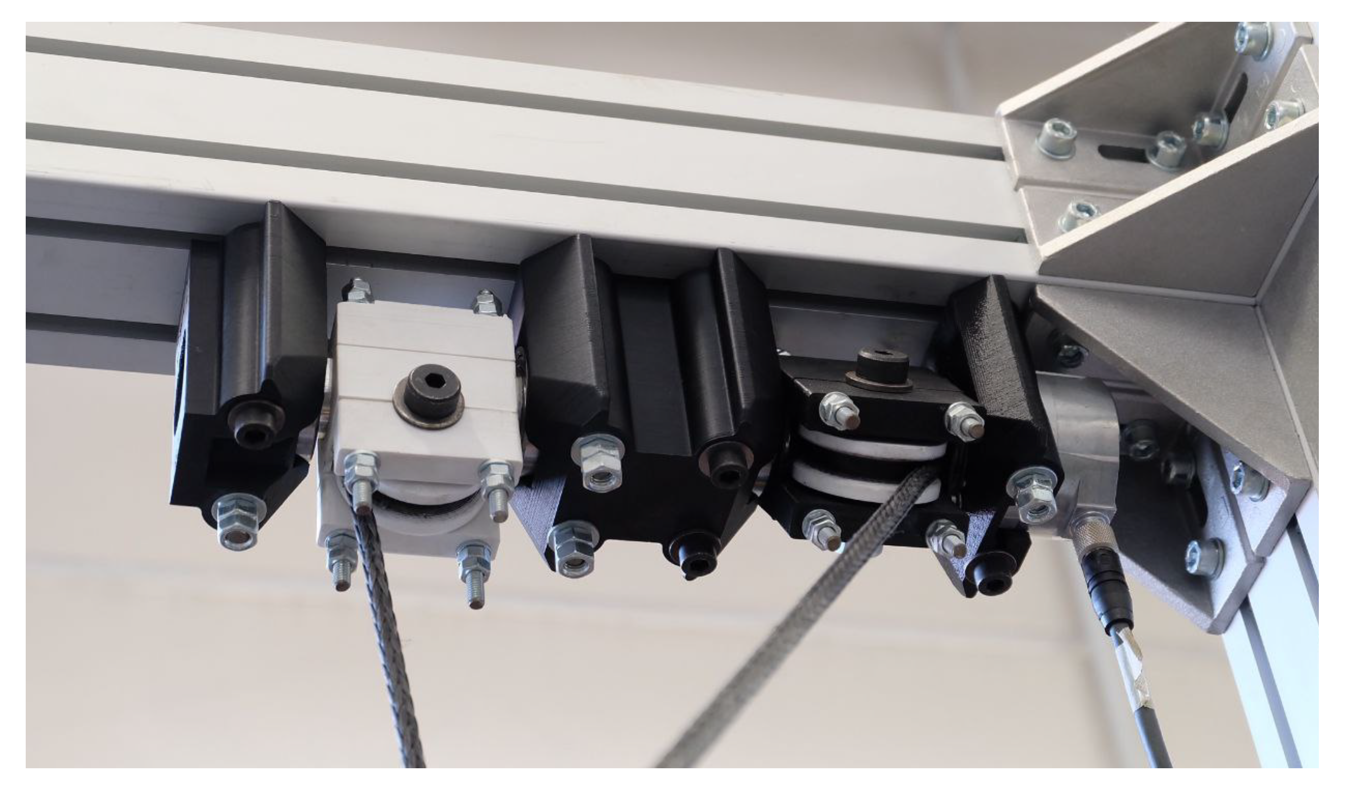
The cable, which leaves the drum groove from a fixed point in space, in a fixed direction (see
Section 3.1), is then guided on a fixed pulley (1) attached to a tension measurement unit, which will be analyzed later on. After that, to obtain a parallelogram shape, the cable passes through four identical swivel pulleys (2,3,4,5) and then, through another fixed pulley (6) (also included in the tension measurement unit) before engaging the other groove on the drum. The proposed cable-loop arrangement realized with one cable avoids possible cable slackness during
EE motion, which may happen if the parallelogram is made of two separate cables driven by the same winch. Two of the swivel pulleys (2,5) are fixed to the base and form the proximal guidance unit, while the other two (3,4) are attached to the platform and form the distal guidance unit. The distance
a between the two pulleys composing each group is equal. This defines the first two sides of the parallelogram, which are invariant, being distances between points of rigid bodies. The other two sides
b are formed by cable sections that are equal and parallel when the cable is taut by design.
3.2.1. Sensor Integration
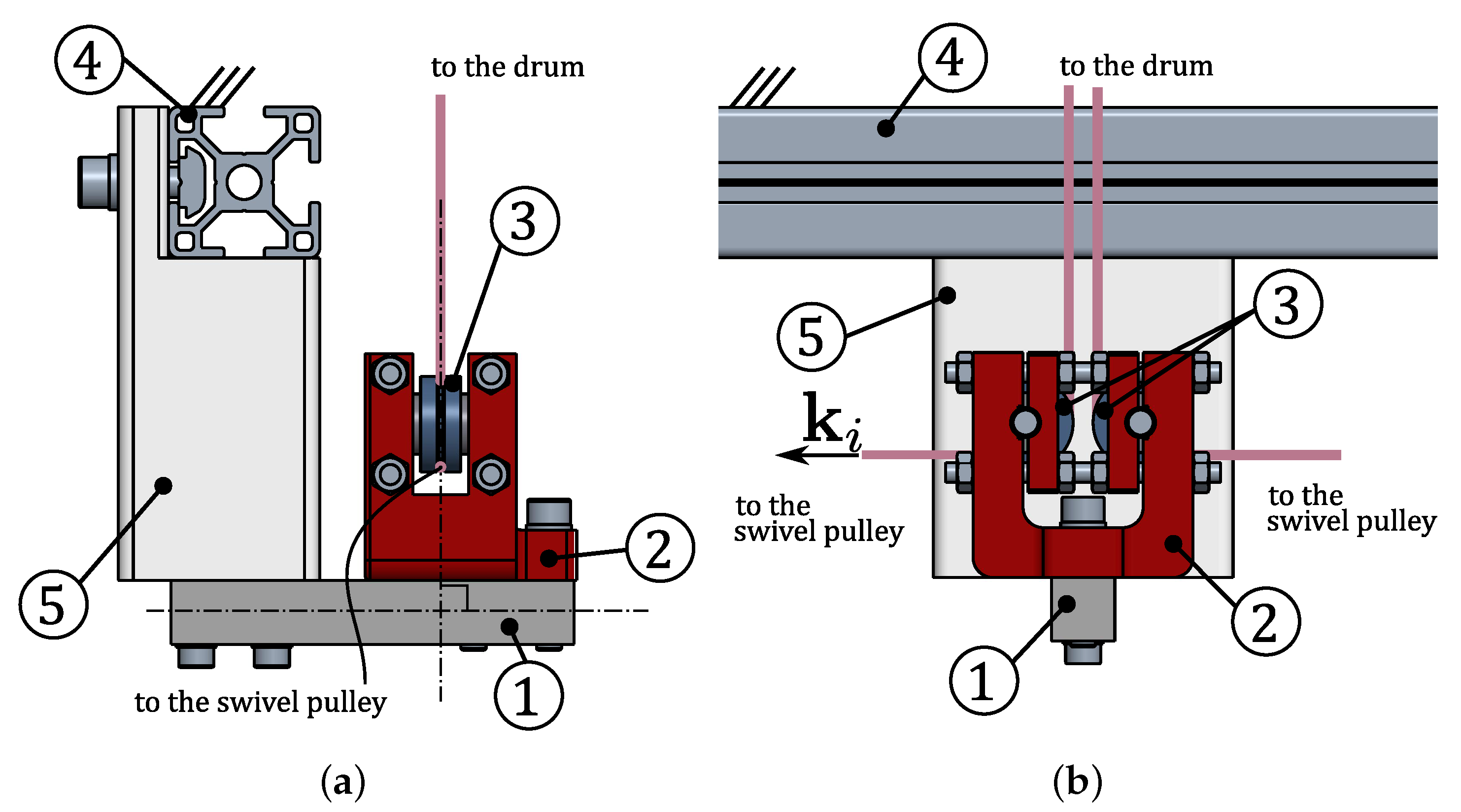
The
CDPR guidance system is often equipped with position [
47] and force sensors [
48] to monitor the robot performance in real-time, if required by the control strategy. In this prototype, one of the swivel pulleys of the proximal group is equipped with an incremental encoder. The encoder is coaxial with the swivel pulley, thus it measures the angle between the cable and the frame: this feature can be used for platform pose estimation through direct kinematics [
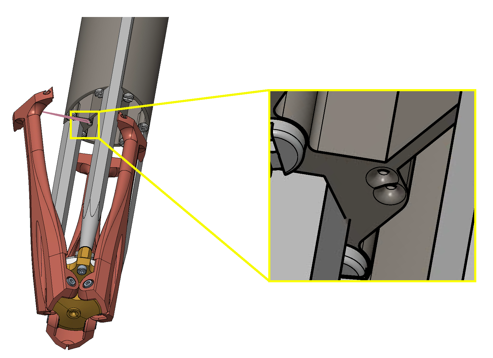
49]. In addition, the fixed pulleys of the proximal guidance group are equipped with a load sensor, a shear beam load cell (Phidget CZL635 micro load-cell, load range 20 kg).
Figure 11 shows the force measurement unit: the load cell (1) is directly connected to the pulley support (2) and structurally constraints the fixed pulleys (3) to the machine frame (4) via an auxiliary bracket (5). The system is designed for the load direction of the pulley to be always orthogonal to the shear beam load cell, to ensure the optimal working conditions of the sensor. The load cell, ideally, measures the double of the cable tension value.
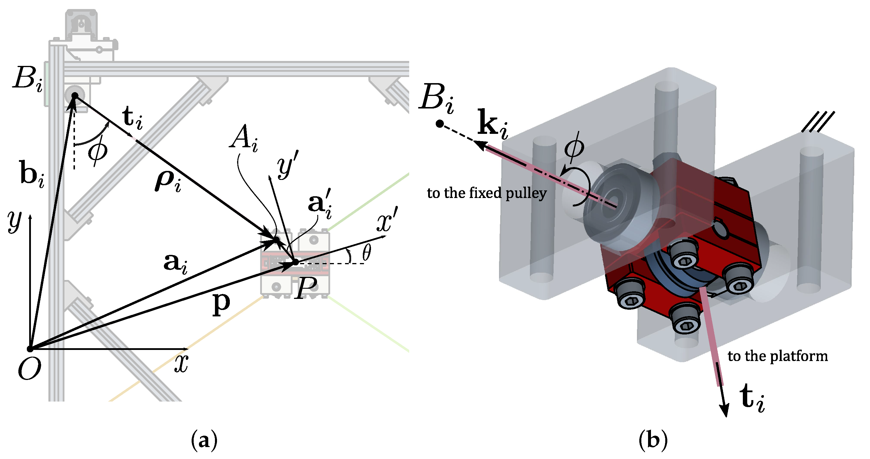
3.2.2. Kinematic Model
To define the cable exit points, each of the four swivel pulleys forming the guidance system is oriented so that its swivel axis, identified by the unit vector
(
Figure 11b and
Figure 12b) is orthogonal to the work plane, that is a vertical plane. The two pulleys, forming the proximal or distal guidance units, are coaxial, and the projection of their swivel axes onto the vertical plane identifies the cable exit points (
, for
for the proximal point in
Figure 12a,b). Thus, the kinematic
standard model can be used without causing geometrical modeling errors. Angle
defines the rotation of the pulley about the swivel axis.
is the unit vector of the
i-th cable.
Considering one of the four cable transmissions (
Figure 12),
and
are defined as inertial and mobile frames. The mobile frame is attached to the platform center of mass
P, described as
with respect to the inertial frame. Cables, assumed massless and inextensible, are considered as the line segments between the distal and proximal anchor points, defined by the pulley swivel axes (
and
respectively, for
). Points
are described by vectors
in the inertial frame, and points
are described by
and
in the mobile and inertial frame, respectively. The rotation matrix
(
) represents the orientation of the moving platform in the vertical plane. The platform pose is defined as
, and
i-th cable vector is:
For a given
EE pose, the
i-th cable length
and unit vector
can be computed as:
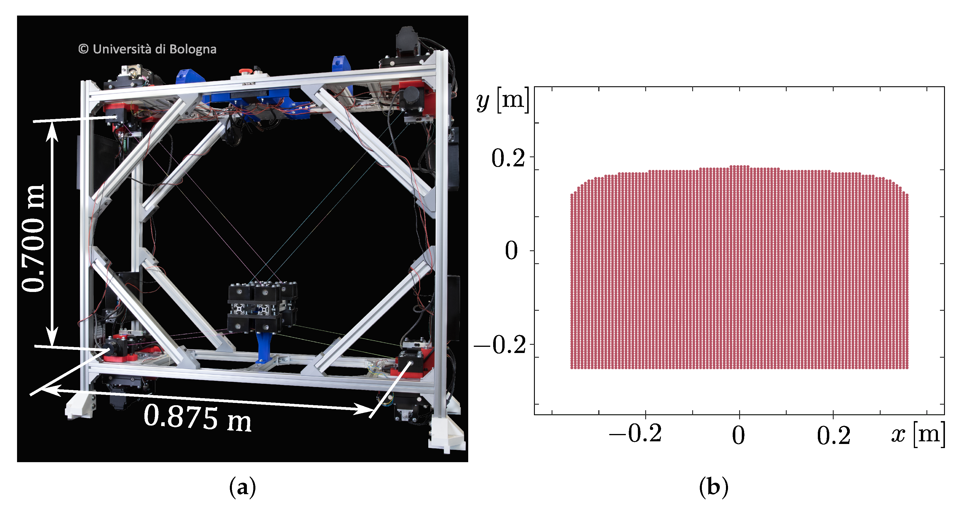
4. Experimental Demonstration: Laser Engraving
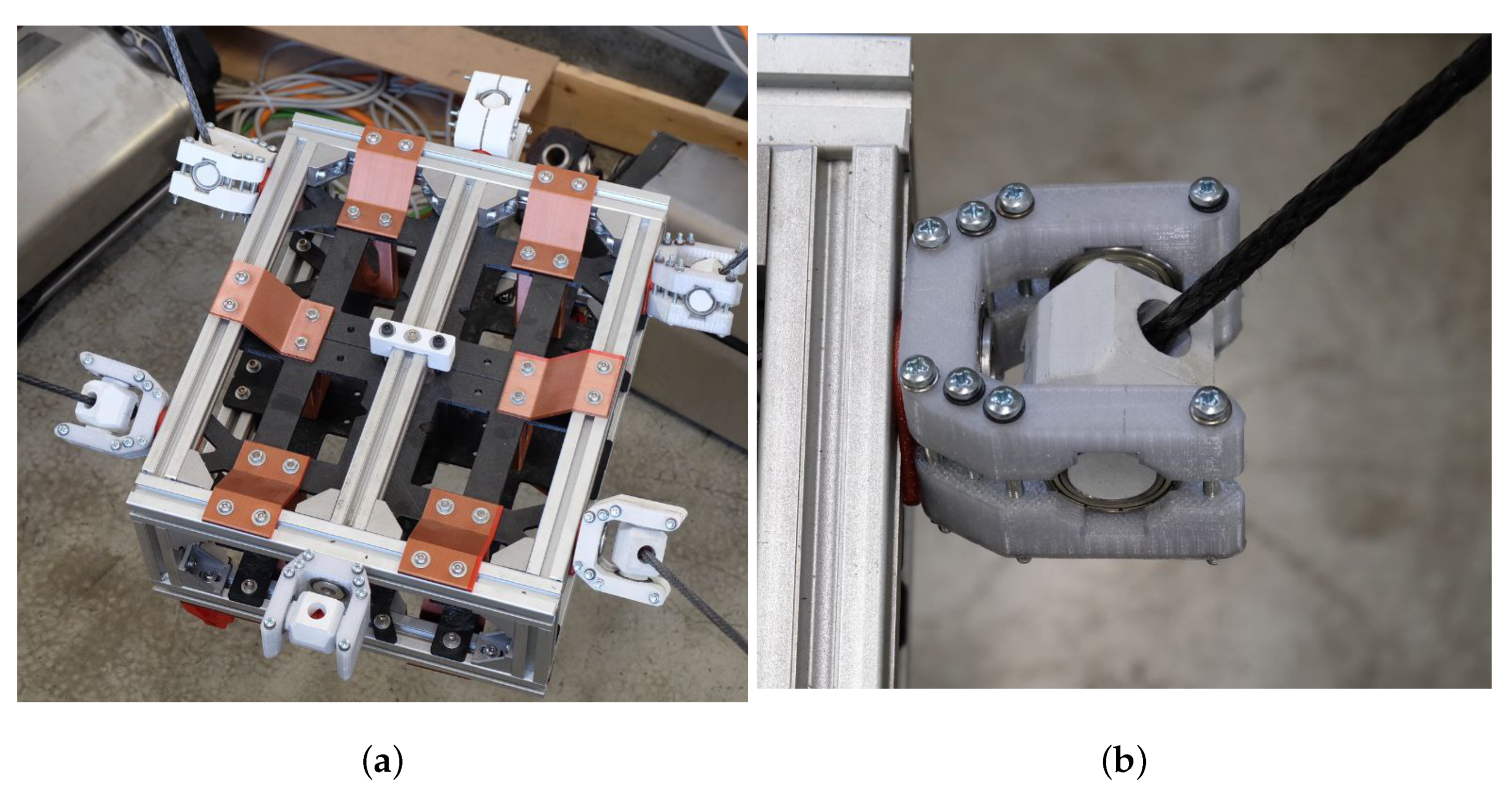
A prototype of a 3-DoF 4-cable
CDPR with a
crossed layout was built at IRMA L@B of the University of Bologna (
Figure 13a). It employs 4 of the actuation systems described in
Section 3.1, connected to the corners of an aluminum frame, and 4 guidance units, whose distal swivel pulleys are bolted to the robot platform. The
CDPR has rectangular base (
) and mobile platform (
). The inertial frame
is located in the center of the base and the moving frame
is located at the center of the
EE, coinciding with its center of mass. Its wrench-feasible translational workspace [
50] is represented in
Figure 13b with a regular discrete grid of
points, considering the platform mass equal to
, and
and
as cable tension limits.
The
CDPR is controlled by a Real-Time Linux PC, which runs its control algorithm at 1 kHz rate, and feeds motor commands through Ethercat protocol [
51] to low-level servo drives. The low-level controller is also developed in-house and run on a ST Nucleo-H743ZI development board at 10 kHz: in addition to controlling motor angles, this allows to directly feed a cable-tension command to the drive. This latter feature simplifies the adoption of the hybrid-input control strategy for the
CDPR described in [
50]: once an
EE-pose set-point is assigned in the Cartesian space, 3 cables are length controlled (i.e., motor angles are commanded to the drives), and one cable is tension controlled (i.e., cable tension is commanded to the drive, and the error with respect to the readings of the load cell is compensated).
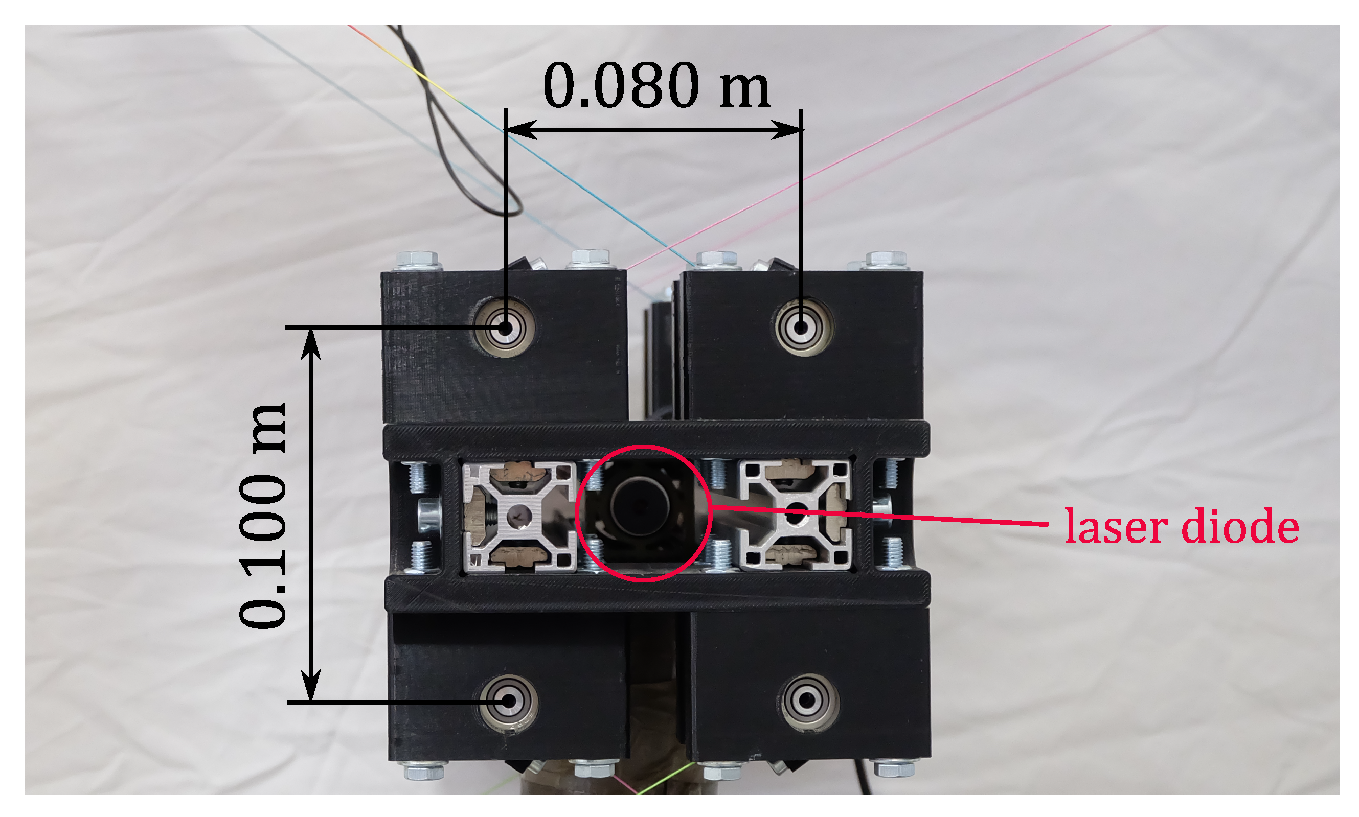
A 2.5 W laser diode is mounted on the robot
EE so that its focal axis is perpendicular to the working plane (
Figure 14), thus allowing the engraving of a paper sheet (for additional details, see
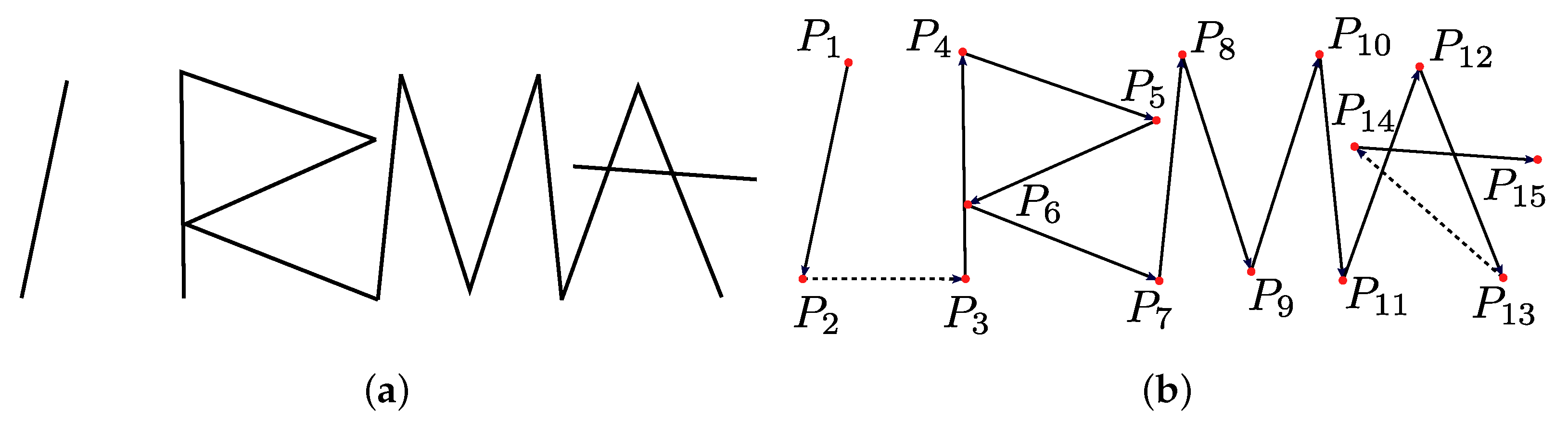
Supplementary Video Material). The name of our laboratory, IRMA L@B, was stylized in a way that every letter was a union of a finite number of linear segments (
Figure 15a): accordingly, a quantitative comparison between the digital model and the engraved result could be performed, by comparing each segment length. A series of consecutive points
, with
, were extracted from the digital model (
Figure 15b), and the robot reference point commanded to follow the path between them with a trapezoidal velocity profile in the task space, while keeping the orientation identically zero. If the trajectory is expressed as:
the motion law
[
52] takes the form:
Since the set-points
of Equation (
3) are set by the task, the only parameters to be determined are
v and
of Equation (
4). They represent, respectively, the motion law maximum speed, and the ratio between the accelerating phase duration and the total time; they are set considering the requirements of the technological operation to be performed. Since the diode laser can only be on or off, the accelerating phase duration should be as limited as possible, to avoid burning the paper when the
EE is moving too slow; on the other hand, motors have limited power, and too quick accelerations may result in their stall: by trial and error,
was established as a good compromise. The motion law maximum speed was instead calculated so as the
EE maximum translational speed was optimal for the engraving operation, namely
m/s for the 2.5 W laser diode at hand; thus, by differentiating Equations (
3) and (
4) we get:
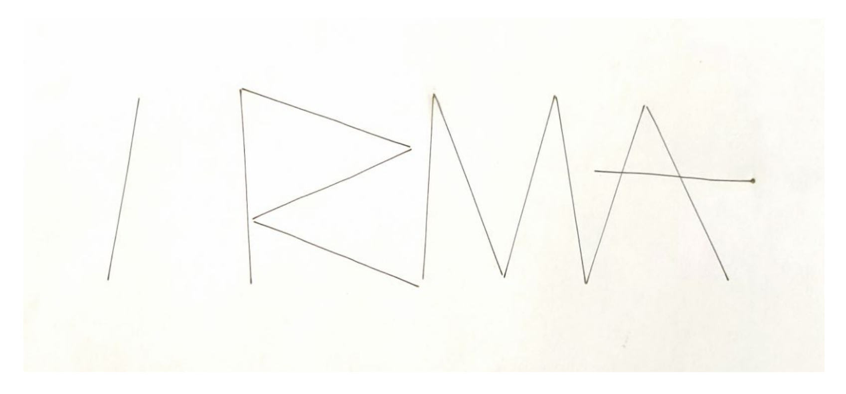
The engraving operation of the stylized
IRMA L@B was then performed, and the result is shown in
Figure 16. First of all, it can be noticed that rectilinearity of the segments is qualitatively good (see
Figure 17a). Small out-of-plane vibrations were excited by the laser diode cooling fan when the laser was switched on and off at the beginning and the end of each segment. This is nearly unnoticeable even scaling up the engraved paper (see
Figure 17b), and it was ultimately expected: a vibration-damping device, such as the one proposed in [
27], can be added to prevent such small-magnitude effects.
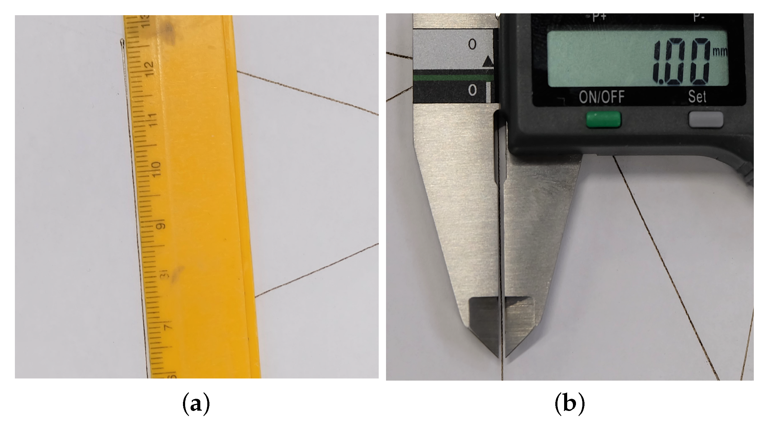
From a quantitative point of view, the ideal length
of each segment was compared to the engraved one
, measured on the paper with a digital caliper (maximum measuring error of 0.3 mm at full scale, 180 mm). If the error is defined as
and the percentage error is
, the root-mean-square error was 2 mm, and the root-mean-square percentage error was
(complete results can be found in
Table 1). Considering the size of the robot workspace and its prototypal nature (most of the components are 3D printed in plastic material), errors of this magnitude are reasonably attributed to an imperfect calibration, mounting errors of the guidance system on the aluminum frame, and elastic components deflection. All in all, the machine can perform the planar non-contact task with relatively good accuracy, which can be increased with a more advanced mechanical design, followed by a precise calibration.


