Article

Performance Analysis of Rate Splitting in Massive MIMO Systems with Low Resolution ADCs/DACs

by
Roger Kwao Ahiadormey
and
Kwonhue Choi
*
Department of Information and Communication Engineering, Yeungnam University, Gyeongsan 38541, Korea
*
Author to whom correspondence should be addressed.
Appl. Sci. 2021, 11(20), 9409; https://doi.org/10.3390/app11209409
Submission received: 7 September 2021 / Revised: 30 September 2021 / Accepted: 4 October 2021 / Published: 11 October 2021

Abstract

:
In this paper, we propose rate-splitting (RS) multiple access to mitigate the effects of quantization noise (QN) inherent in low-resolution analog-to-digital converters (ADCs) and digital-to-analog converters (DACs). We consider the downlink (DL) of a multiuser massive multiple-input multiple-output (MIMO) system where the base station (BS) is equipped with low-resolution ADCs/DACs. The BS employs the RS scheme for data transmission. Under imperfect channel state information (CSI), we characterize the spectral efficiency (SE) and energy efficiency (EE) by deriving the asymptotic signal-to-interference-and-noise ratio (SINR). For 1-bit resolution, the QN is very high, and the RS scheme shows no rate gain over the non-RS scheme. As the ADC/DAC resolution increases (i.e., 2–3 bits), the RS scheme achieves higher SE in the high signal-to-noise ratio (SNR) regime compared to that of the non-RS scheme. For a 3-bit resolution, the number of antennas can be reduced by 27% in the RS scheme to achieve the same SE as the non-RS scheme. Low-resolution DACs degrades the system performance more than low-resolution ADCs. Hence, it is preferable to equip the system with low-resolution ADCs than low-resolution DACs. The system achieves the best SE/EE tradeoff for 4-bit resolution ADCs/DACs.

1. Introduction

In massive multiple-input multiple-output (MIMO), base stations (BSs) are equipped with a large number of antennas to simultaneously serve user terminals by spatial multiplexing [1]. Massive MIMO uses linear processing to achieve high spectral efficiency (SE) and energy efficiency (EE) [1,2,3]. Massive MIMO systems can operate in the time division duplex (TDD) mode, where the uplink (UL) is utilized for channel state information (CSI) estimation and the downlink (DL) for data transmission [4]. However, imperfect CSI obtained from UL training decreases the system performance.
Rate-splitting (RS) is a promising multiple access scheme that received a surge of interest in recent years [5,6,7]. In RS multiple access, the transmitter splits each user’s message into two parts namely: a common part and a private part [5]. The common messages are encoded into one stream using a public codebook. The private messages are encoded into individual streams. The common stream is superimposed with the private streams of all users. It is assumed that the receivers decode the common message with zero error probability and their corresponding private messages by applying successive interference cancellation (SIC). Both RS multiple access and nonorthogonal multiple access (NOMA) utilize SIC at the receivers [6,7,8]. However, RS multiple access is a generalized technique that includes NOMA as a special case [6,7,8]. The advantage of RS over NOMA lies in the fact that the RS scheme partially decodes interference and treats the remaining part as noise, while the NOMA scheme needs to fully decode the interference from other users. Therefore, the RS strategy is a robust interference management technique outperforming NOMA with a lower computational complexity in various network settings [6,7]. The RS scheme also improves the achievable degrees-of-freedom (DoF) compared to that of NOMA [9]. Rate-splitting was also shown to enhance the EE of DL MISO transmission [10,11].
In massive MIMO systems, RS multiple access was first proposed in a frequency division duplex (FDD) system to mitigate the effects of imperfect CSI [12]. The authors derived the asymptotic sum-rate of the RS scheme. The RS scheme performs better than the conventional non-RS schemes in terms of SE. Based on the results, a novel hierarchical rate-splitting (HRS) scheme was proposed which exploits the DL channel statistics for additional rate performance. The authors of [13] extended the results of [12] to a TDD massive MIMO system, where the BS and users suffer from hardware impairments. Compared to that of the conventional non-RS scheme, the RS scheme is able to enhance the sum-rate, especially in the presence of hardware impairments caused by phase noise and amplified thermal noise [13]. Furthermore, RS multiple access is a robust strategy to combat the effects of residual self-interference (SI) and intracell pilot contamination in massive MIMO systems [14,15].
To realize the SE and EE gains, massive MIMO systems are analyzed by assuming high-quality perfect hardware in the literature. However, the radio-frequency (RF) components suffer from high hardware cost and circuit power consumption due to the large number of antennas at the BSs. Analog-to-digital converters (ADCs) and digital-to-analog converters (DACs) are the dominant power hungry components at the BS. The power consumption of ADCs and DACs grows exponentially as the number of quantization bits increases [16]. The use of low-resolution ADCs and DACs emerged as a possible solution to reduce the hardware cost and power consumption in massive MIMO transceiver designs [17]. Several works proposed and analyzed different architectures such as one bit, low bit resolution (e.g., 1–3 bits), and variable bit resolution for massive MIMO systems [18,19,20,21,22,23]. In [18], the authors analyzed the DL achievable rate in a one-bit massive MIMO with matched filter (MF) precoding. The rate loss incurred can be compensated by using 2.5 times more antennas at the BS. The work in [19] considered active eavesdropping in a secure massive MIMO where the effects of ADC/DAC quantization are modeled by the additive quantization noise model (AQNM). The authors proposed the use of artificial noise (AN) to mitigate the effects of active eavesdropping. The results showed that optimal power allocation is necessary to reduce the rate loss caused by high QN and improve the secrecy of the system. The authors of [20] studied the performance of FD massive MIMO systems with low-resolution ADCs/DACs. By considering perfect CSI, closed-form expressions for the UL and DL achievable rates under Rayleigh fading were derived. The work in [20] was extended to Rician fading channels [21] where imperfect CSI case was also analyzed. In [22,23], the impact of quantization on the SE and EE of FD massive MIMO systems was considered for Rician fading. However, the works in [21,22,23] did not account for the impact of low-resolution ADCs on the CSI estimation. Assuming perfect CSI and regularized zero-forcing (RZF) precoding, Xu et al. analyzed the optimal user loading in a massive MIMO system where BS is equipped with low-resolution DACs and the users are equipped with finite resolution ADCs [24].
Conventional massive MIMO relies on linear precoding techniques such as MF, zero-forcing (ZF), and RZF precoding to achieve high SE and EE performance in multiuser systems [25]. Of the three, RZF precoding is the state-of-the-art since it offers the best performance since it boosts the desired signal energy and mitigates the interference to other users [25]. These linear precoding techniques were shown to mitigate the effects of the quantization noise (QN) to some extent [18,20,21,24]. However, using low-resolution ADCs/DACs at the transceivers causes a rate loss. In conventional non-RS schemes, to cope with the high QN from low-resolution ADCs/DACs, the number of antennas needs to be increased, which causes a high complexity burden to the systems [18,20,21]. Comparatively, the RS scheme was shown to be a robust strategy to enhance the SE and mitigate interference in massive MIMO systems with imperfect CSI [12], hardware impairments [13], and residual SI [14], respectively. However, there were no studies on RS multiple access in massive MIMO with low-resolution ADCs/DACs. We propose RS multiple access as an effective alternative to this issue. By employing a properly designed RS scheme in massive MIMO systems with low-resolution ADCs/DACs, higher SE can be achieved compared to that of the conventional non-RS scheme, even with less number of antennas than that of the conventional scheme.
In the paper, we consider the DL of a multiuser massive MIMO system where the BS is equipped with low-resolution ADCs and DACs. Different from [13], where a generalized hardware impairment model is investigated, we focus on the effect of QN due to the low-resolution quantization bits and its impact on the SE/EE. In contrast to existing works [21,22,23], we account for the impact of the low-resolution ADCs on the channel estimates in the UL training phase [26]. In the DL, the low-resolution DACs distort the transmit signal by introducing QN. We consider the MF beamformer and regularized zero-forcing (RZF) precoder for the common and private messages, respectively [12,13,14]. While the RZF precoder was investigated in massive MIMO systems with low-resolution ADCs/DACs [24], the results were only derived for perfect CSI. In contrast, the results in our work are derived for the imperfect CSI case. The main contributions of this work are summarized as follows:
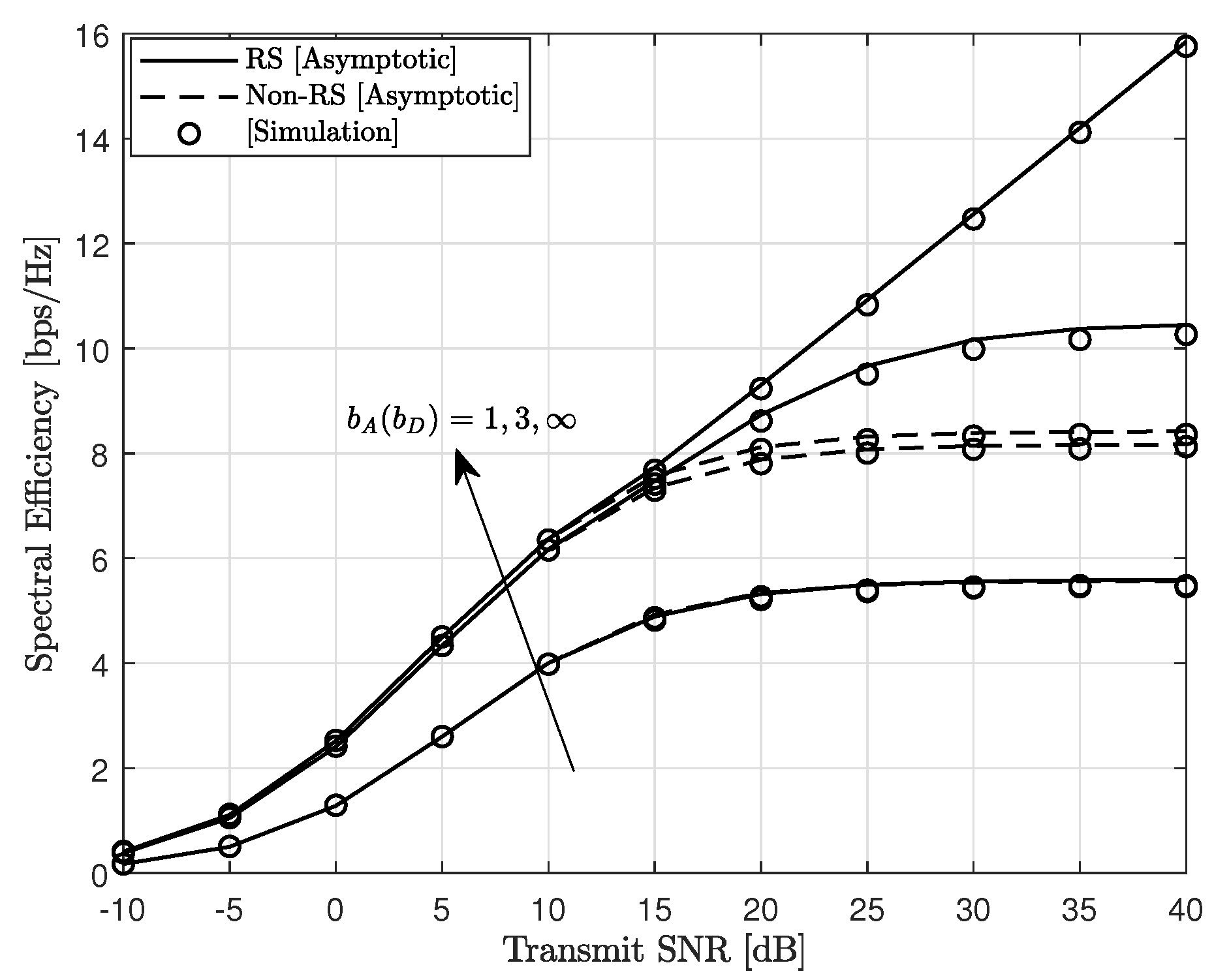
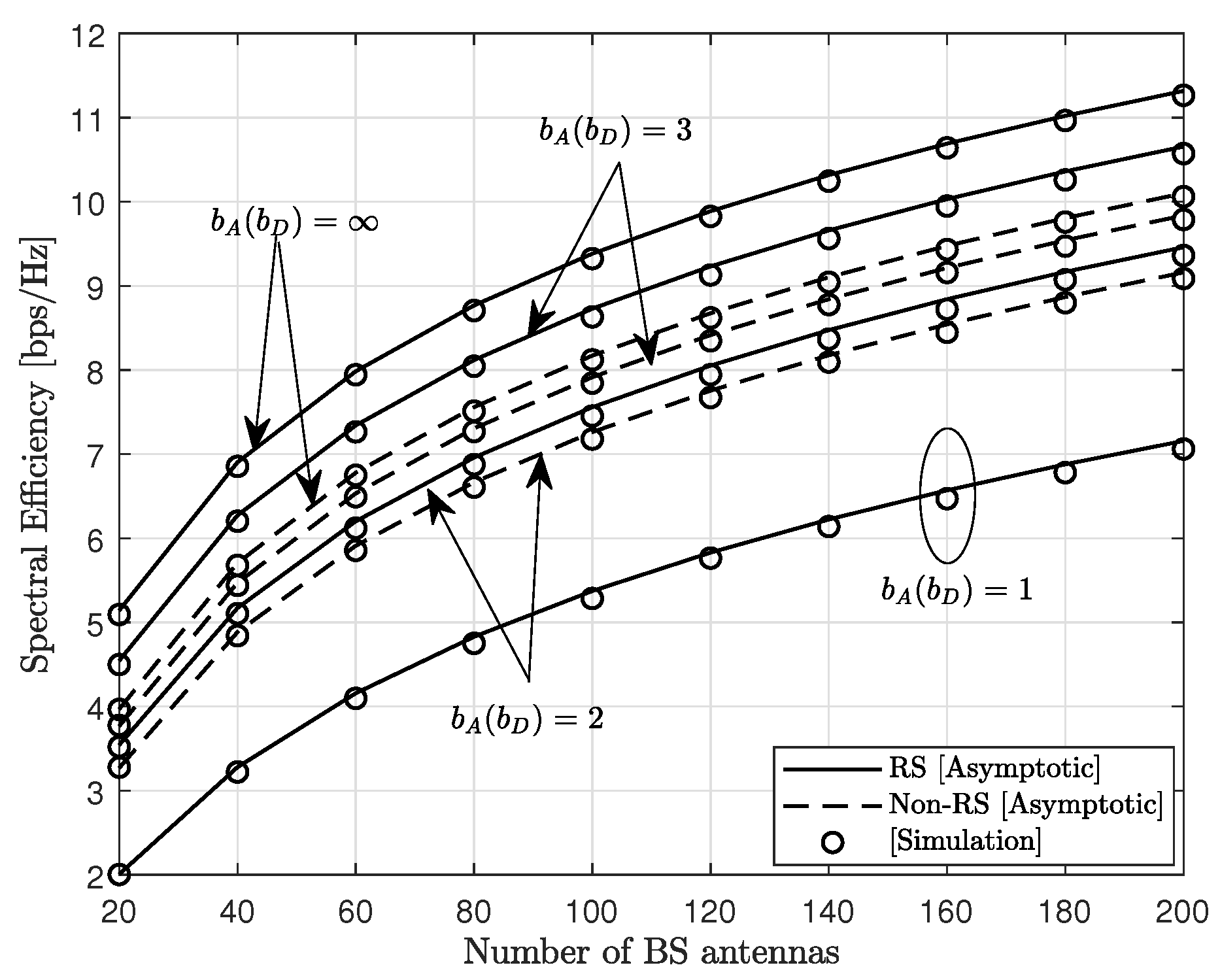
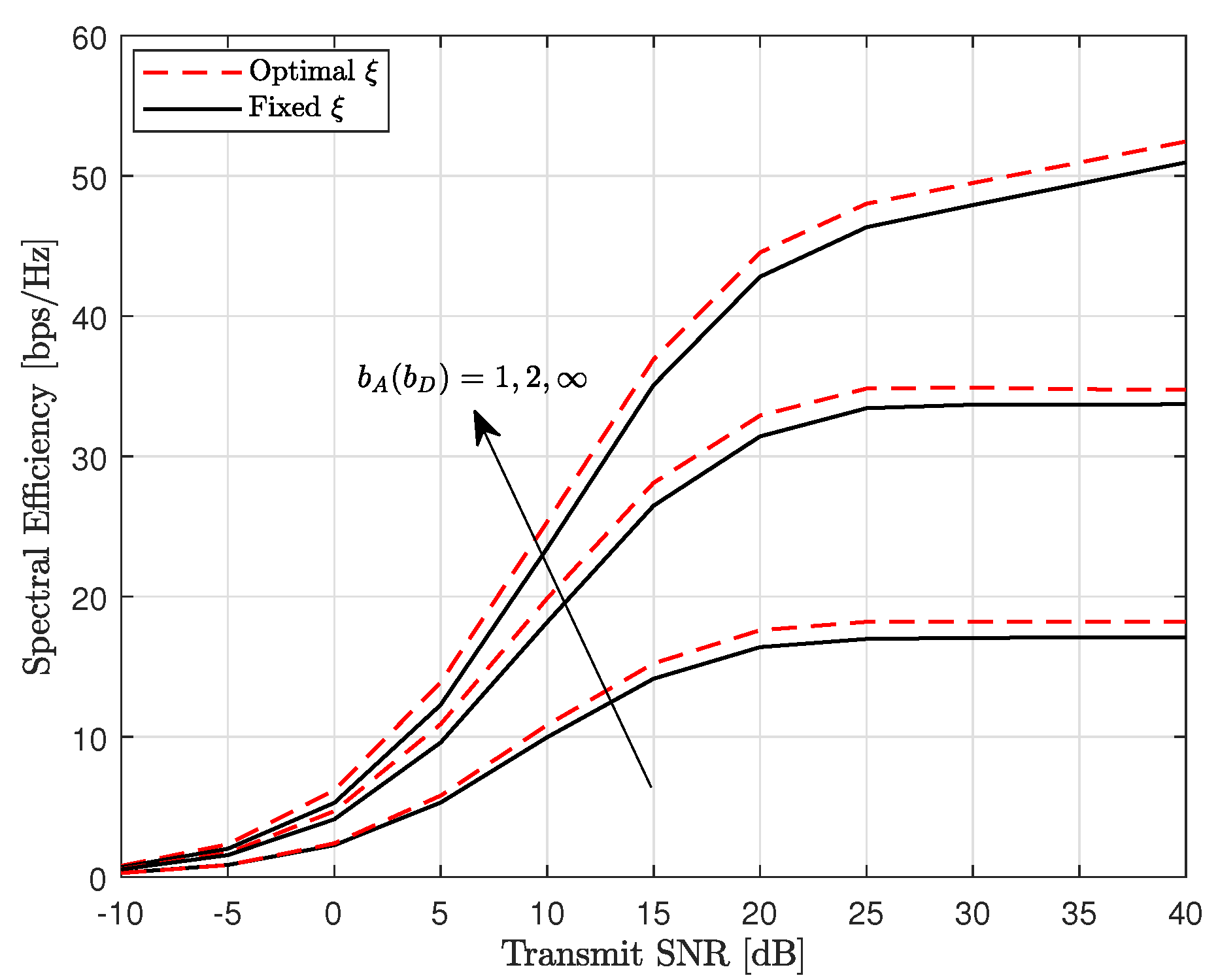
  • We derive the signal-to-interference-and-noise ratios (SINRs) of the common and private messages of the RS scheme in the asymptotic regime. Numerical results demonstrate the effectiveness of the RS scheme to achieve higher SE than the non-RS scheme for 2–3 bit resolution ADCs/DACs. We show that the RS scheme with QN (e.g., 3 bits) outperforms the conventional non-RS scheme with no QN (i.e., ideal ADCs/DACs) with reduced number of antennas. For low-resolution ADCs only, the SE of the RS scheme is an increasing function of the signal-to-noise ratio (SNR). This trend is opposite to the conventional non-RS scheme where the SE saturates at high SNR.
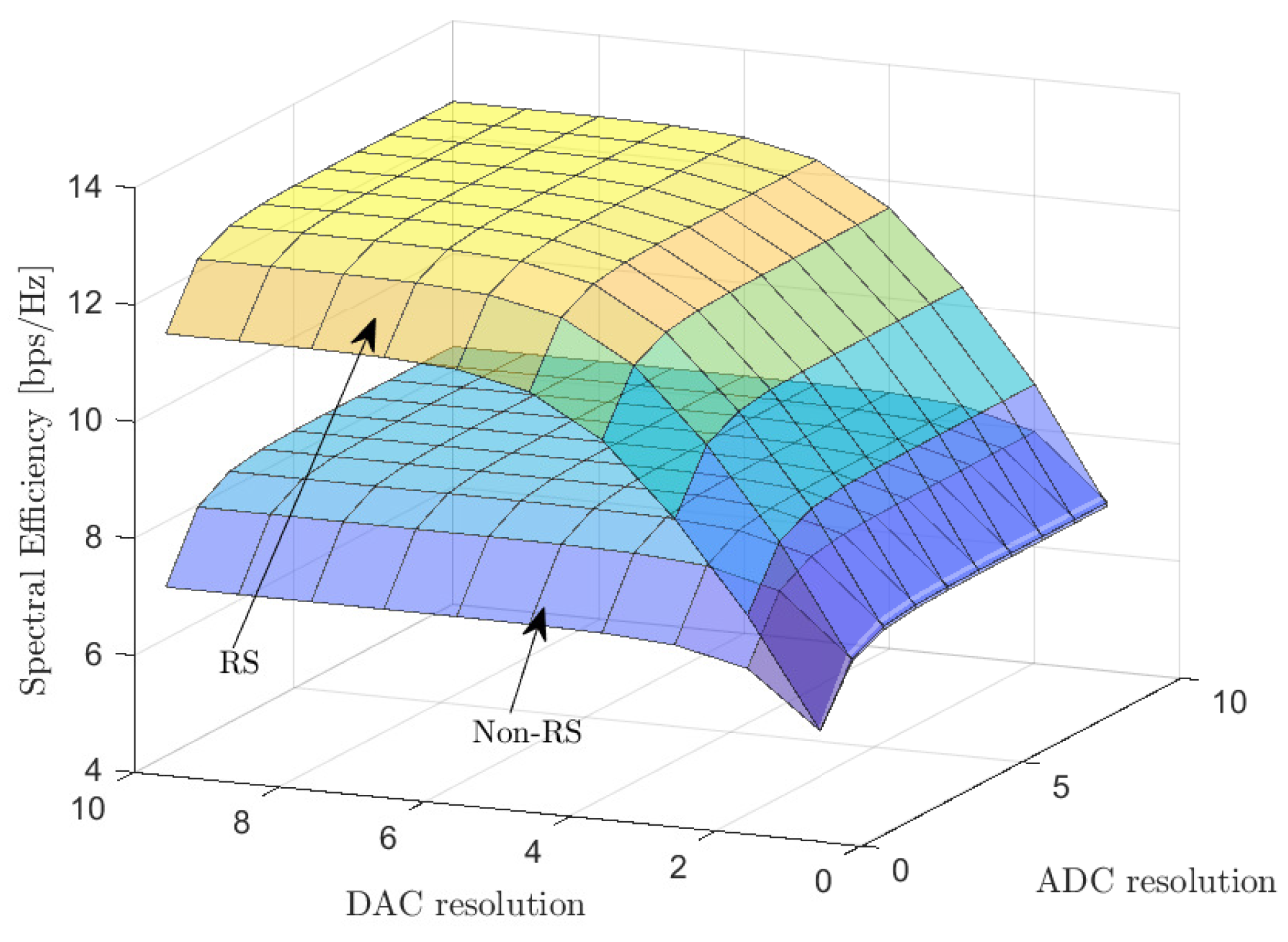
  • We derive a closed-form power allocation solution for the common and private messages. Differently from [12], the solution takes into account not only the multiuser interference, but also the QN. From the results, low-resolution DACs have a more dominant effect on the SE performance than low-resolution ADCs. Hence, low-resolution ADCs are preferred to low-resolution DACs for increased SE performance.
  • Contrary to existing works [12,13,14] where the optimal regularization parameter is not analyzed, we derive the optimal regularization parameter for the RZF precoder accounting for the effects of quantization.
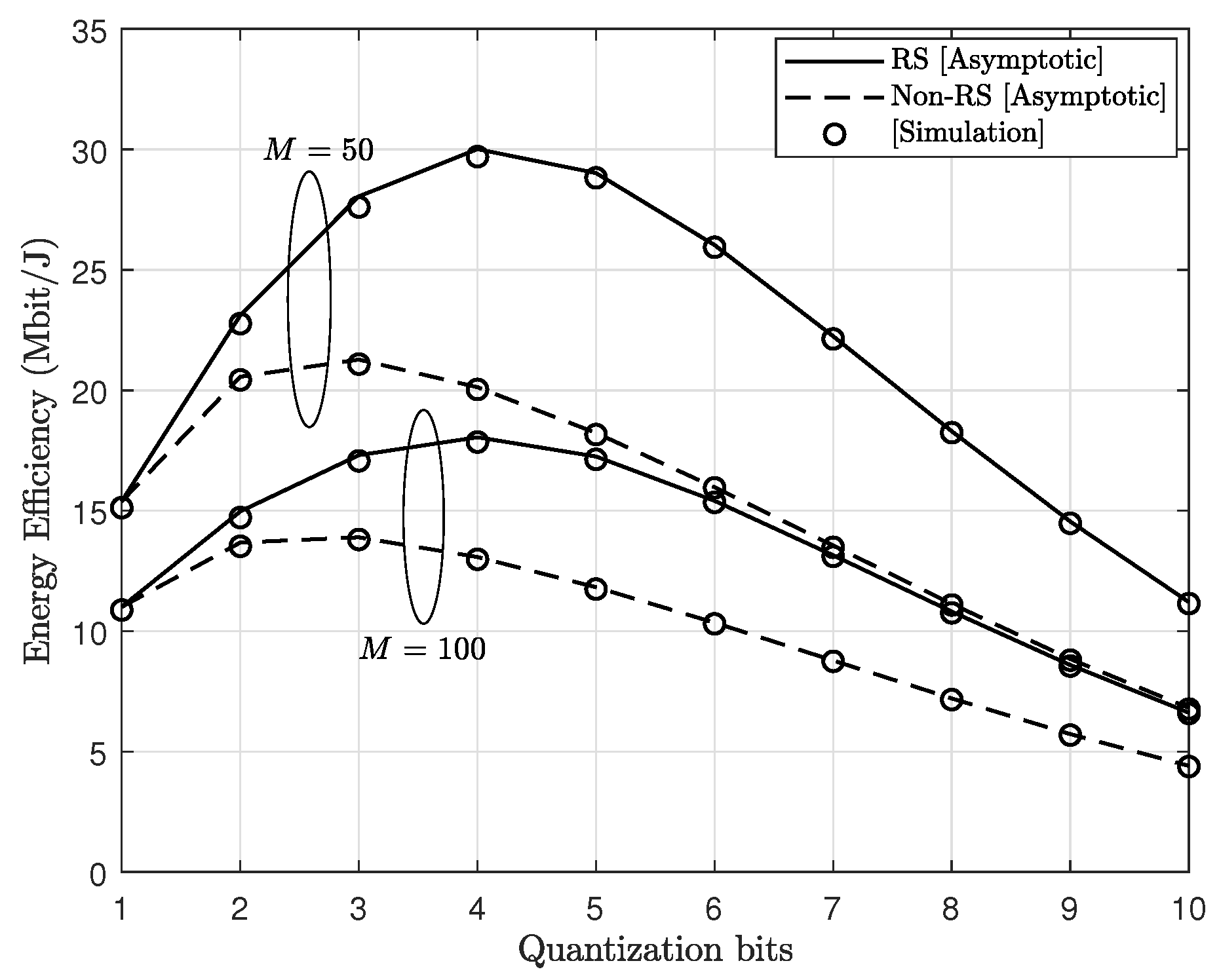
  • We introduce a power consumption model for the ADCs/DACs, and we analyze the SE/EE tradeoff as a function of the quantization bits.
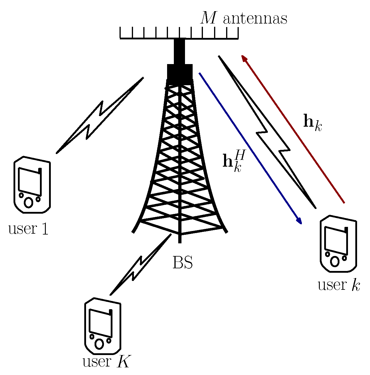
The paper is organized as follows. In Section 2, we introduce the system model of the massive MIMO system and describe the proposed RS scheme. In Section 3, we derive the SINRs of the common and private messages in the asymptotic regime and the corresponding SE. Furthermore, we analyze the power allocation and regularization parameter. Section 4 focuses on the EE analysis. In Section 5, we present the simulation results and discussions. Finally, Section 6 concludes the paper.
Notation 1.
In this paper, boldface lower and uppercase symbols denote vectors and matrices, respectively. The symbols ( · ) H , Tr ( · ) , and E { · } , denote the conjugate transpose, trace and expectation operators, respectively. C N ( μ , σ 2 ) denotes a circularly symmetric complex Gaussian distribution with mean μ and variance σ 2 . diag ( X ) returns the diagonal elements of a matrix X . The matrix I M denotes an M × M identity matrix.

2. System Model

Consider a multiuser massive MIMO system as illustrated in Figure 1. The BS, equipped with M antennas, serves K single-antenna users in the same time-frequency resource. All nodes operate in the HD mode. To reduce the power consumption and hardware complexity, the BS is fitted with low-resolution ADCs/DACs. The low-resolution ADCs affect the channel estimation in the UL training phase while the low-resolution DACs affect the DL transmit signal quality. The BS uses the RS scheme for DL multiuser transmission. We consider a block fading channel where the channel is unchanged during the coherence interval. We assume a Rayleigh fading channel model where the channel between the BS and all K users, H C M × K , is modeled as [27]
H = G D 1 2 ,
where G C M × K denotes the channel matrix containing the small scale fading having independent and identically distributed (i.i.d.) C N ( 0 , 1 ) entries. The channel matrix D C K × K is a diagonal matrix containing the large scale fading in terms of the kth diagonal entries denoted by β k . In this work, the large scale fading coefficient, β k , is modeled in dB scale as [28]
β k = 148 + 37.6 log 10 ( d k ) + z k ,
where d k is the distance from the BS to the kth user and z k denotes the shadow fading term. The channel between the BS and the kth user is denoted by h k where h k is the kth column of H .

2.1. Uplink Channel Estimation

Through UL training, the BS estimates the UL channel vectors of the users. The BS can acquire the DL CSI by exploiting channel reciprocity enabled by the TDD operation. For a coherence time interval of length τ , we use τ p sequence for the channel estimation. The remaining ( τ d = τ τ p ) sequence is used for DL transmission In Internet of Things (IoT) scenarios, discontinuous transmissions may exist. In this case, the coherence time interval can be written as τ = τ p + τ d + τ n where τ n denotes the time interval when the channel is not used. In this work, we consider the case where τ n = 0 so that the rest of the coherence time interval is used for data transmission [29]. We assume that τ p K orthogonal pilot sequences are transmitted to avoid pilot contamination.
Figure 2 shows the receiver structure of the BS in the UL channel estimation phase. Before passing through the low-resolution ADCs in Figure 2, the received pilot signal at the BS is expressed as
Y p = τ p P p H Φ p + N p ,
where P p and N p denote the pilot power and the additive white Gaussian noise (AWGN) at the BS with i.i.d. C N ( 0 , 1 ) elements. The mutually orthogonal pilot sequence Φ p C K × τ p is transmitted from the K users such that Φ p Φ p H = I K .
Since the BS is equipped with low-resolution ADCs, this affects the quality of the channel estimates. We adopt the well-known AQNM to characterize the effect of low-resolution quantizers. In MIMO systems, where the separate ADCs operate at each antenna, a lot of quantized signals are summed to generate decision variables for data symbols. Therefore, due to central limit theorem, the QN at the decision variable can be well approximated Gaussian even with very low-resolution ADCs. This also holds for the QN due to low-resolution DACs. From [30], the Gaussian approximation provides a lower capacity bound of the quantized system. The AQNM was shown to be analytically tractable and accurate in the low- and medium-SNR regions [16,17]. After passing through the low-resolution ADC quantizers, the resulting signal at the BS becomes
Y ^ q = Q ( Y ^ p ) = α A τ p P p H Φ p + α A N p + N q ,
where Q ( · ) and α A denote the quantization operation and the linear gain of the ADC quantizer, respectively. The exact values of α A , which depend on the quantization bits, b A , which be found in [19]. The matrix N q denotes the quantization noise which is uncorrelated with Y p . The covariance matrix of N q is expressed as
R N q = E { N q N q H } = α A ( 1 α A ) diag Y q Y q H .
Using the minimum mean square error (MMSE) estimator [2], the channel matrix H is decomposed as [2]
H = H ^ + E ,
where H ^ and E represent the estimated channel matrix and the estimation error matrix of H , respectively. The channel from the BS to the kth user, h k , is further written as
h k = h ^ k + e k ,
where the elements of h ^ k and e k are independent Gaussian random variables with zero mean and variances denoted by λ k and ϵ k , respectively, given as [19]
λ k = α A τ p P p β k 2 1 + τ p P p β k , and ϵ k = β k λ k .

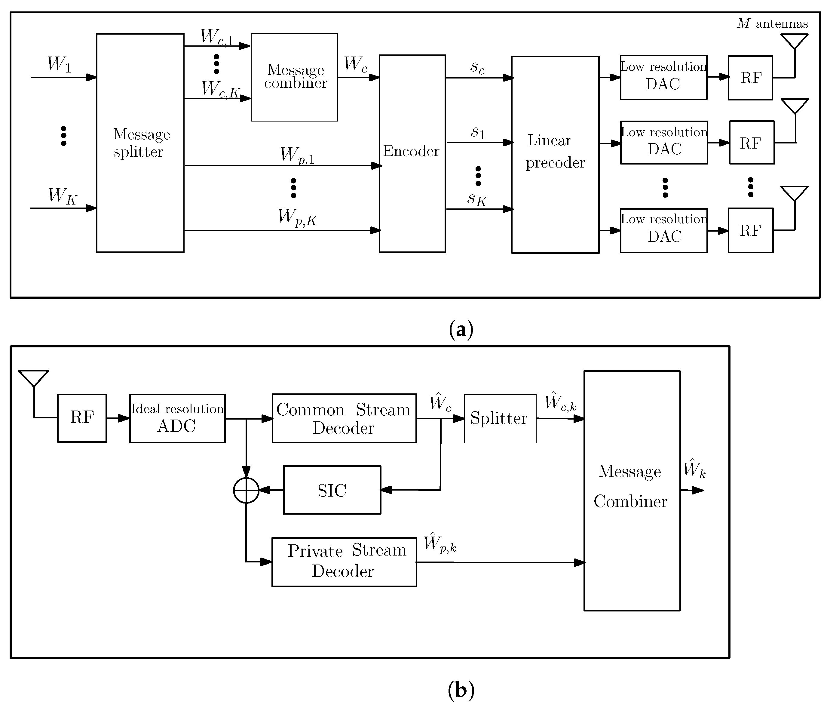
2.2. Downlink Data Transmission Using Rate-Splitting Scheme

During the DL data transmission, the BS applies the RS scheme for data transmission to the K users. The transmitter structure is depicted in Figure 3a. Denote the uncoded messages intended for the kth user as W k , ∀ k = { 1 K } . Firstly, the BS splits each user’s message, W k , into two parts: a common part, W c , k , and a private part, W p , k using the message splitter. Next, the common parts from all users are encoded into a single common stream, s c using a common codebook. This enables all users to decode the common stream and extract their messages. Also, each private part, W p , k is individually encoded into a private stream, s k . Then, properly designed linear precoders are applied to the encoded common and private streams, respectively. The linearly precoded signals then pass through the low-resolution DACs and RF chain for transmission. The transmit signal of the RS scheme before DAC quantization is expressed as
x = P c w c s c + k = 1 K P k w k s k ,
where x , s c C N ( 0 , 1 ) , and s k C N ( 0 , 1 ) denote the superimposed signal, the common stream, and the private message of the kth user, respectively [31]. Furthermore, w c and w k represent the precoders for the common message and private message of the kth user, respectively, and the powers allocated to the common message and the private message of the kth user are denoted respectively by P c and P k . For the private message, we assume equal power allocation to all K users. Hence, P c and P k can be further expressed as P c = P ( 1 t ) and P k = P t / K P d k where P represents the total DL power budget and t ( 0 , 1 ] is the power allocation factor.
Consequently, the received signal at the kth user is given by
y k = h k H x + n k ,
where n k is the AWGN at the kth node distributed as n k C N ( 0 , 1 ) .
Since the BS is equipped with low-resolution DACs, the transmit signal, x , is distorted by quantization noise. Using the AQNM, the transmit signal after DAC quantization, x ^ , takes the form
x ^ = Q ( x ) = α D x + n D ,
where Q ( · ) denotes the quantization operation and α D is a linear gain which depends on the number of quantization bits, b D . Please see Table 1 for values of α D [19]. The additive Gaussian quantization noise denoted by n D is uncorrelated with x . The covariance matrix of n D is expressed as
R n D = α D ( 1 α D ) diag E { x x H } , = α D ( 1 α D ) diag P c w c w c H + P d k = 1 K w k w k H .
To satisfy the power constraint of the signal before quantization x , a normalization factor of 1 / α D is applied to (11) [19].
At the kth user, the transmitted signal is decoded as shown in Figure 3b. Firstly, the user decodes the common stream by treating all private streams as noise. Then, the user can recover its common message. Next, the user removes the decoded common message from the composite signal by SIC. After this, the user decodes its own private message. Using this process, each user obtains its desired message by combining the decoded common and private messages. To facilitate the analysis, we rewrite (10) by using (9) and (11) as
y k = α D P c h k H w c s c + α D P d h k H w k s k + j k K α D P d h k H w j s j + h k H n D + n k .
From (13), the achievable rates of the common and private message for the kth user are respectively expressed as
R k , c = τ τ p τ log 2 ( 1 + SINR k , c ) ,
and
R k = τ τ p τ log 2 ( 1 + SINR k , p ) ,
where SINR k , c and SINR k , p denote the SINRs of the common and private messages, respectively. The SINRs of the common message and the private message of the kth user are respectively given by
SINR k , c = α D P c h k H w c 2 α D P d k = 1 K h k H w k 2 + h k H R n D h k + 1 ,
and
SINR k , p = α D P d h k H w k 2 α D P d j k K h k H w j 2 + h k H R n D h k + 1 .
The SE for the system under consideration is obtained as [13]
R SE = R c + k = 1 K R k ,
where R c = min k K R k , c since the common message must be decoded at all users.

3. Performance Analysis

In this section, we analyze the SE of the rate-splitting based massive MIMO system with low-resolution ADCs/DACs. We consider the results in the asymptotic regime where K and M grow to infinity but the ratio θ = K / M remains constant. Firstly, we derive the asymptotic SINRs of the common and private messages, respectively. The asymptotic results enable us to draw useful insights into the impact of the various system parameters such as the number of BS antennas, quantization bits, and the number of users, respectively. Next, to obtain the full benefits of the RS scheme, the power allocation to the common and private messages needs to be carefully considered. Using the asymptotic SINR results, we derive an analytic power allocation solution and the optimal regularization parameter. We show that the power allocation depends on the low-resolution ADCs/DACs and highlights the rate gain of the RS scheme over the conventional non-RS scheme in the massive MIMO system.

3.1. Asymptotic Analysis

In this section, we derive the asymptotic SINRs for the common and private messages of the kth user, respectively. Due to the TDD protocol, the precoders w c and w k are designed using the estimated channel obtained in the UL training phase. Similar to [12,13,14], we consider the MF beamformer and RZF precoders for the common and private messages, respectively. In the asymptotic regime, when the number of BS antennas tends to infinity, the common message precoder is designed as a linear combination of the estimated channel vectors between the BS and the users [32]. The BS can assign different weights to the channel vectors to maximize the precoder performance. In this work, we consider the MF beamformer with equal weights to all users for analytic tractability [12]. The common message precoder is given by
w c = ϱ f ^ c ,
where f ^ c = k = 1 K h ^ k and ϱ = 1 / E { | | f ^ c | | 2 } denotes the normalization constant.
For the private messages, we use the RZF precoder to strike a balance between the desired signal energy and the amount of interference leakage to other users. If we define a precoder matrix W such that the kth column of W is equal to w k , then the RZF precoder is expressed as
W = κ ( H ^ H ^ H + M δ I M ) 1 H ^ ,
where δ is the regularization parameter that minimizes the interference to other users. A typical value of δ is δ = K / ( M P ) [12]. This parameter will be optimized in later section. The normalization constant, κ , is given by
κ = K Tr { H ^ H ( H ^ H ^ H + M δ I M ) 2 H ^ } .
Based on the precoders, it is difficult to derive the SINRs in finite system dimensions. Therefore, we analyze the SINRs in the large system limit where K and M→∞ but the user loading ratio θ = K / M remains fixed [33]. Closed-form solutions for the asymptotic SINRs are derived in the following theorem.
Theorem 1.
By considering the effect of low-resolution DACs and ADCs at the BS and imperfect CSI, the asymptotic SINRs of the common message and private message of the kth user are respectively derived as
SINR k , c = α D P c ϱ 2 M 2 λ k 2 ( 1 + f ( θ , ξ ) ) 2 K α D P d λ k f ( θ , ξ ) 1 + ξ θ 1 + f ( θ , ξ ) 2 + K α D P d λ k 1 + ϵ k λ k 1 + f ( θ , ξ ) 2 + Ω ,
and
SINR k , p = K α D P d λ k f ( θ , ξ ) 1 + ξ θ 1 + f ( θ , ξ ) 2 K α D P d λ k 1 + ϵ k λ k 1 + f ( θ , ξ ) 2 + Ω ,
where
f ( θ , ξ ) = 1 2 ( 1 θ ) 2 ξ 2 + 2 ( 1 + θ ) ξ + 1 + ( 1 θ ) ξ 1 ,
Ω = ( 1 α D ) P β k + 1 ( 1 + f ( θ , ξ ) ) 2 , ϱ = 1 / M k = 1 K λ k , and ξ = δ / M , respectively.
Proof. 
Please refer to Appendix A. □
Remark 1.
From (22) and (23), we observe the impact of the various parameters on the SINRs of the common and private messages, respectively. As expected, the SINRs of the common and private messages are an increasing function of the number of BS antennas, linear gain of the ADC/DAC resolution, and transmit power of the common message. The SINR of the common message is a decreasing function of the number of users. Therefore, the performance of the RS scheme degrades rapidly for higher number of users and high-QN. Since the QN is coupled with the transmit power, the SINRs of both common and private messages saturate at high-SNR and -QN.

3.2. Power Allocation

Here, we analyze the power allocation for the private and common messages, respectively. We obtain the power allocation factor, t, based on the metric developed in [12]. We obtain a closed-form closed-form solution based on the asymptotic results and show how the RS scheme outperforms the conventional non-RS scheme in massive MIMO. The main idea of this heuristic technique is to allocate power to the private messages to achieve approximately the same SE as the non-RS scheme. Then, the remaining power is allocated to the common message to enhance the SE. For the massive MIMO system with low-resolution ADCs/DACs, the solution takes into account not only the multiuser interference but also the QN. The SE gain of the RS scheme over the conventional scheme with RZF precoding is quantified as [12]
Δ R = R c + k = 1 K ( R k , p R k , R Z F ) ,
where R k , R Z F is the rate for the non-RS scheme where the BS uses RZF precoder and zero power is allocated to the common message in (9). The power allocation factor for the private messages, t, is derived as
t = min Ψ , 1 ,
where
Ψ = K + ( 1 α D ) K P β k α D P ϵ k + ( 1 α D ) P β k + ( 1 α D ) K P β k .
Remark 2.
From (27), when the QN is high, more power is allocated to the private messages. Hence, the rate gain of the RS scheme which depends on the common message cannot be improved. Consequently, the rate gain of the RS scheme over the non-RS scheme is degraded for an increasing number of users and for low-resolution ADCs/DACs. Also, the QN due to low-resolution DACs has a more dominant effect on the SE performance than that of the low-resolution ADCs.

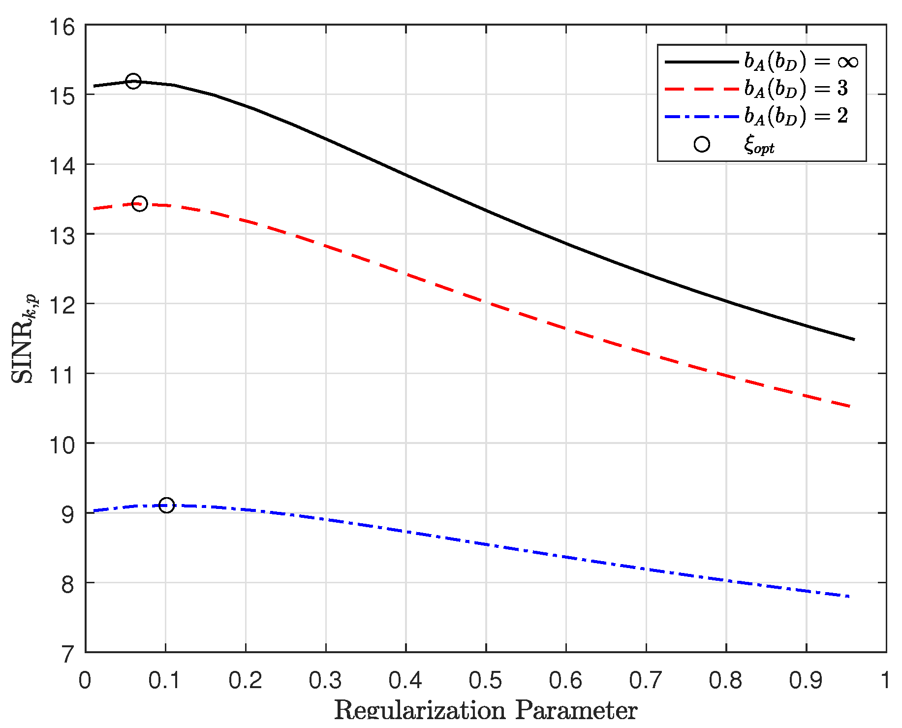
3.3. Optimal Regularization Parameter

In this section, we derive the optimal regularization parameter, ξ , for the RZF precoder and study the impact of low-resolution ADCs/DACs. To derive the optimal regularization parameter, we rewrite the SINR of the private message in (23) as
SINR k , p = ρ f ( θ , ξ ) 1 + ξ θ ( 1 + f ( θ , ξ ) ) 2 ρ + ( 1 + f ( θ , ξ ) ) 2 ,
where ρ is expressed as
ρ = α D P d λ k α D P d ϵ k + ( 1 α D ) P β k + 1 .
By setting the derivative of (28) with respect to ξ to zero SINR k , p ξ = 0 and with some algebraic manipulations, the optimal regularization parameter is derived as [34]
ξ opt = θ ρ .
Remark 3.
From the result in (30), the optimal regularization parameter is a function of the user loading ratio, and the resolutions of ADCs and DACs. As the QN due to the low-resolution DACs increases, ρ decreases. Hence, there is a corresponding increase in ξ opt to mitigate the effect of QN introduced by the low-resolution ADCs/DACs.

4. Energy Efficiency Analysis

In this section, we analyze the EE of the massive MIMO with low-resolution ADCs/DACs. The ADCs and DACs are one of the high power consuming components of the RF chains at the BS and the power consumption grows exponentially with the number of quantization bits. Although high-resolution ADCs and DACs enhance the SE, the EE suffers as a result of the high power consumption. Equipping the massive MIMO systems with low-resolution ADCs/DACs sacrifices the SE performance but the EE can be improved. Therefore, it is imperative to study the EE in the proposed RS massive MIMO system. From [35], the EE is defined as
EE = B × R SE P total bit / Joule ,
where R SE and P total denotes the SE given by (18) and B represents the system bandwidth. We set a system bandwidth of B = 20 MHz . Moreover, P total is the total power consumption at the BS. We consider the power consumption model in [16,22,35]. The P total is expressed as
P total = M P mix + P filt + 2 P syn + M P LNA + P mix + P IFA + P filr + M ( ζ A + ζ D ) P AGC + P DAC + P ADC ,
where P PA , P mix , P filt , P syn , P LNA , P IFA , P filr , P AGC , P DAC , and P ADC denote the power consumption of the power amplifier (PA), the mixer, the active filters at the transmitter side, the frequency synthesizer, low-noise amplifier (LNA), the intermediate frequency amplifier, the active filters at receiver side, the automatic gain control (AGC), DACs, and ADCs, respectively [35]. Furthermore, ζ A and ζ D are the flags related to the bit resolution of the DACs and ADCs, respectively, where ζ A ( ζ D ) = 0 if b A ( b D ) = 1 and ζ A ( ζ D ) = 1 if b A ( b D ) > 1 . The power consumption of the DACs and ADCs are related to the bit resolution by [35]
P DAC = 1 2 V dd I 0 ( 2 b D 1 ) + b D C p ( 2 B + f cor ) V dd 2 ,
and
P ADC = 3 V dd 2 L min ( 2 B + f cor ) 10 0.1525 b A + + 4.838 ,
where V dd , I 0 , C p , f cor , and L min denote the power supply of converter, the unit current source corresponding to the least significant bit (LSB), the parasitic capacitance of each switch in the converter, the corner frequency of the 1 / f noise, and the minimum channel length for the given complementary metal oxide semiconductor (CMOS) technology, respectively [35]. In the simulation results, we set the following values to calculate the EE [35]: P mix = 30.3 mW , P filt = P filr = 2.5 mW , P syn = 50 mW , P LNA = 20 mW , P IFA = 3 mW , P AGC = 2 mW , V dd = 3 V , I 0 = 10 μ A , C p = 1 pF , f cor = 1 MHz , and L min = 0.5 μ A , respectively.

5. Simulation Results

In this section, we present numerical results to evaluate the SE/EE performance of the massive MIMO system. All numerical results are obtained using MATLAB. Unless otherwise stated, we set the following parameters M = 100 and K = 2 , respectively. Furthermore, we assume a coherence interval of τ = 200 symbols with τ p = K for channel estimation. The pilot power is set as P p = 2 dB . The transmit SNR is defined as SNR P . We assume that the users are randomly distributed in a cell of dimensions 500 m × 500 m. The users are at least 35 m from the BS. The large scale fading coefficient is modeled as (2) and a standard deviation of 7 dB is set for z k . In all simulation results, the RS scheme is compared to the non-RS scheme, which is RZF linear precoding [12,13,14].
In Figure 4, we investigate the performance of the power allocation solution obtained in (26). We plot the power allocation factor, t, against the bit resolution for different number of users (i.e., K = 2 and K = 5 ). When the QN is very high i.e., b A ( b D ) = 1 , the RS scheme achieves the same SE as that of the non-RS scheme since all power is allocated to the private messages. As the bit resolution increases, the fraction of power allocated to the common message (i.e., 1-t) is increased. Hence, the rate gain of the RS scheme over the non-RS scheme can be realized. In addition, when the number of users increases from K = 2 to K = 5 , the power allocated to the common messages is reduced, which in turn degrades the performance of the RS scheme.
Figure 5 shows the SE versus the transmit SNR. We compare the performance of the RS scheme to that of the conventional non-RS scheme for different number of users when b A ( b D ) = 3 . The SE for RS scheme is plotted by substituting (22) and (23) into (18). The SE for non-RS scheme is obtained by setting P c = 0 . From Figure 5a, the asymptotic results are very tight compared to that of the simulation results verifying the accuracy of our analysis. The RS scheme achieves a higher SE than that of the non-RS scheme. The SE of both schemes saturates at high SNR due to the multiuser interference and QN. In Figure 5b, we show in detail the SE performance of the private and common messages. For the RS scheme, power is allocated to the private messages to achieve almost the same SE as that of the non-RS scheme. In the high SNR region, the remaining power is allocated to the common message to enhance the SE. The power allocation factor is obtained using the closed-form expression in (26). Furthermore, as the number of users increases from K = 2 to K = 5 , the SE increases for both schemes due to the spatial multiplexing gains. For the RS scheme, increasing the number of users decreases the power allocation to the common message in the high-SNR region. The rate gain reduces but the RS scheme still performs better than the non-RS scheme.
Figure 6 depicts the SE versus the transmit SNR. For Figure 6a, we fix the resolution of the DACs and vary the resolution of the ADCs. The effect of the low-resolution ADCs is captured only in the quality of channel estimates. This is reflected as the factor α A in (8). For the RS and non-RS schemes, the SE increases for increasing ADC quantization bits. The proposed RS scheme overcomes the effect of the multiuser interference and the SE increases at high-SNR. This is opposite to the non-RS scheme where the SE saturates at high-SNR due to multiuser interference. Furthermore, we observe the rate gain of the RS scheme over that of the non-RS scheme. For b A = 2 and at 25 dB, the RS scheme shows a gain of about 2.5 bps/Hz (34% increase) over the non-RS scheme. For Figure 6b, we fix the resolution of the ADCs and vary the resolution of the DACs. The effect of the low-resolution DACs is captured in the factor α D and the QN term h k H R n D h k in (16) and (17), respectively. For the same level of quantization, the performance of RS scheme with low-resolution DACs only (i.e., 2 bit to 1 bit) degrades faster and saturate at high SNR due to the combined effect of multiuser interference and the QN term. Therefore, low-resolution DACs have a more dominant effect on the SE performance than that of low-resolution ADCs.
Next, Figure 7 illustrates the SE versus the transmit SNR for different bit resolution of ADCs/DACs. We assume equal ADC/DAC quantization bits in the evaluation. When the QN is high (i.e., b A ( b D ) = 1 ), the RS scheme is unable to overcome the QN and multiuser interference of the low-resolution ADCs/DACs. Hence, the rate gain is negligible. As b A ( b D ) increases, the RS scheme can still outperform the non-RS scheme under the effects of QN. The RS scheme with quantization achieves bigger SE compared to that of the conventional non-RS scheme with no quantization. For example, the RS scheme for b A ( b D ) = 3 outperforms the non-RS scheme with b A ( b D ) = by 22% in terms of the SE.
In Figure 8, we show a 3D surface plot of the SE as a function of ADC and DAC quantization bits. We consider only the asymptotic results and compare the SE performance of the RS and non-RS schemes. For both schemes, the lowest SE is achieved when b A ( b D ) = 1 . In this case, the RS scheme offers no gain over the non-RS scheme. As the quantization bits of the ADCs and DACs increase, the rate gain of the RS scheme over the non-RS scheme becomes evident. The highest SE is achieved for high-resolution ADCs and DACs i.e., b A ( b D ) = 10 . From the figure, the low-resolution DACs play a more dominant role in determining the SE performance compared to that of the low-resolution ADCs. This is because the rate gain decreases more with the low-resolution DACs than that of the low-resolution ADCs. Hence, it is preferable to equip the massive MIMO system with low-resolution ADCs than low resolution DACs.
Figure 9 plots the SE against the number of BS antennas. We investigate the impact of the BS antennas on the SE performance for different quantization bits. From the figure, the SE performance is improved for more BS antennas for both schemes. For higher quantization bits, the RS scheme shows better performance than that of the non-RS scheme and can achieve the same SE with a lower number of BS antennas. Compared to that of the non-RS scheme, the number of antennas needed to achieve an SE of 7 bps/Hz in the RS scheme reduces by about 11% when b A ( b D ) = 2 . For b A ( b D ) = 3 , number of antennas decreases by about 27%. Compared to that of the non-RS scheme, the RS scheme can achieve the same SE with fewer quantization levels. From the figure, the RS scheme can achieve an SE of 8 bps/Hz for b A ( b D ) = 3 and M = 80 . On the other hand, the non-RS scheme achieves the same SE for a higher quantization level with an even larger number of antennas, i.e., b A ( b D ) = and M = 95 . Therefore, the QN effect can be compensated by the proposed RS scheme instead of deploying more antennas.
Figure 10 shows the SE performance versus the number of quantization bits. As shown in the figure, the RS scheme performs better than the non-RS scheme as the bit resolution of the ADCs/DACs increases. Furthermore, as the number of users increases, the power allocated to the common message decreases and the rate gain of the RS scheme is degraded. Therefore, the bit resolution of the ADCs/DACs needed for the RS scheme to outperform the non-RS scheme increases. For K = 2 , the 2 bit resolution ADCs/DACs are required. This increases to 3 bits when K = 5 for the RS scheme to outperform the non-RS scheme.
In Figure 11, we plot the SINR of the private message against the regularization parameter for different quantization bits. We check the accuracy of the derived optimal regularization parameter, ξ o p t , obtained in (30). We observe that the derived solution is accurate since it maximizes the SINR. Moreover, the results confirm the observation in (29) and (30). As the quantization bit decreases, ρ in (29) decreases and the optimal regularization parameter is increased. For instance, the optimal regularization parameter increases from 0.0607 to 0.101 when the quantization bit decreases from b A ( b D ) = 3 to b A ( b D ) = 2 .
Figure 12 shows the SE performance of the RS scheme versus the transmit SNR. We investigate how the optimal regularization parameter, obtained by (30), can increase the SE. In this plot, we consider different level of quantization bits. The optimal ξ improves the SE performance especially in the high-SNR region, where the multiuser interference is dominant. With low-resolution ADCs/DACs, the QN is considered in deriving the optimal regularization parameter which shows an increase in SE for b A ( b D ) = 1 and b A ( b D ) = 2 .
Figure 13 presents the EE versus the number of quantization bits. From the plot, the EE first increases and then decreases as the quantization bits increases. This is due to the fact the higher quantization bits increases the power consumption, which in turn decreases the EE performance. There exists an optimal value of the quantization bits where the EE of the system is maximum. In the figure, maximum EE is achieved when b A ( b D ) = 4 for the RS scheme irrespective of the number of BS anetnnas, M. For the non-RS scheme, maximum EE is achieved at b A ( b D ) = 3 . The EE of the RS scheme is improved compared to that of the non-RS scheme. Furthermore, the BS with a higher number of antennas shows a lower EE since the power consumption increases with the number of BS antennas.
Figure 14 presents the EE/SE trade-off performance by plotting the EE against the SE for different number of quantization bits. The SE and EE are evaluated for the quantization bits from b A ( b D ) = 1 to b A ( b D ) = 10 . From the figure, we observe that the system with lower number of BS antennas (i.e., M = 50 ) shows the highest EE. However, this comes at the expense of lower SE. For M = 100 , the EE decreases due to increased power consumption of the additional BS antennas. Moreover, the RS scheme performance better than the non-RS scheme in terms of EE and SE. For M = 100 , a comparison of the SE and EE is provided in Table 1.

6. Conclusions

In this paper, we analyzed the performance of a rate-splitting multiple access scheme in a massive MIMO system with low-resolution ADCs and DACs. Under imperfect CSI, we characterized the SE and EE derived by the asymptotic SINRs of the common and private messages, respectively. Our results are verified by Monte Carlo simulations. We showed that the proposed RS scheme achieves higher SE than that of the non-RS scheme for low-resolution ADCs and DACs (i.e., 2–3 bits) with an even lower number of antennas. The SE performance is more degraded under the effects of low-resolution DACs compared to that of low-resolution ADCs. Finally, we showed that the best SE-EE trade-off is obtained for the 4-bit resolution ADCs/DACs. For future work, rate-splitting can be considered in the context of mixed ADCs/DACs systems. To extract further gains, hierarchical rate-splitting can also be investigated for massive MIMO with low-resolution ADCs/DACs.

Author Contributions

Conceptualization, methodology, and original draft preparation, R.K.A.; supervision, validation, writing—review and editing, K.C. Both authors have read and agreed to the published version of the manuscript.

Funding

This work was partly supported by the Technology development Program of MSS [S2967489], the National Research Foundation of Korea (NRF) grant funded by the Korean Government (MSIT) under Grant 2021R1A2C1010370, and the 2021 Yeungnam University Research Grant.

Conflicts of Interest

The authors declare no conflict of interest.

Appendix A. Proof of Theorem 1

Firstly, we derive the asymptotic SINR associated with the common message. Based on (7) and (16), the desired signal power of the common message is derived as [33]
| h k H w c | 2 = | { ϱ h k H f ^ c } | 2 , = ( a ) | { ϱ ( h ^ k H + e k H ) f ^ c } | 2 , = ϱ 2 M 2 λ k 2 .
where we use w c = ϱ f ^ c and ϱ is defined as ϱ = 1 / M k = 1 K λ k [33]. Step ( a ) follows from (7) where h k = h ^ k + e k . We obtain the result in (A1) based on the fact that the estimated and error channels are uncorrelated.
To derive the term associated with interference from the private messages, we first rewrite the interference term as
k = 1 K | h k H w k | 2 = | h k H w k | 2 + j k K | h k H w j | 2 .
We derive the first part of (A2), | h k H w k | 2 , as
| h k H w k | 2 = κ 2 | h k H Σ h ^ k | 2 , = ( a ) κ 2 h k H Σ k h ^ k 1 + h k H Σ k h ^ k 2 , = ( b ) κ 2 h ^ k H Σ k h ^ k 1 + h ^ k H Σ k h ^ k 2 , = κ 2 A k 2 ( 1 + A k ) 2 ,
where Σ ( H ^ H ^ H + δ I M ) 1 , Σ k ( H ^ H ^ H h ^ k h ^ k H + δ I M ) 1 , and A k = h ^ k H Σ k h ^ k , respectively. We used the definition of the RZF precoder in (20). Therefore, w k is expressed as w k = Σ h ^ k . Step ( a ) is derived by using the matrix inversion lemma [33]. Step ( b ) follows directly from (7) and the fact that the estimated and error channels are uncorrelated.
Next, we derive the second part of (A2), j k K | h k H w j | 2 , as
j k K | h k H w j | 2 = κ 2 j k K E { | h k H Σ h ^ k | 2 } , = κ 2 | h k H Σ H ^ k | 2 , = ( a ) κ 2 h k H Σ k H ^ k H ^ k H Σ k h k ( 1 + h ^ k H Σ k h ^ k ) 2 , = κ 2 ( B k + E k ) ( 1 + X k ) 2 ,
where H ^ k = H ^ H ^ H h ^ k h ^ k H , B k = h ^ k H Σ k H ^ k H ^ k H Σ k h ^ k , and E k = e k H Σ k H ^ k H ^ k H Σ k e k , respectively. Step ( a ) is derived by using the matrix inversion lemma [33].
Based on the results in [34,36], in the large system limit where K and M but the user loading ratio θ = K / M is constant, A k converges to a deterministic value given by f ( θ , ξ ) in (24). f ( θ , ξ ) is obtained as the solution of the equation
f ( θ , ξ ) = 1 + f ( θ , ξ ) θ + ξ ( 1 + f ( θ , ξ ) ) .
Following the similar approach [34,36], we can show that
B k = f ( θ , ξ ) + ξ ξ f ( θ , ξ ) ,
E k = ϵ k λ k 1 + f ( θ , ξ ) 2 f ( θ , ξ ) + ξ ξ f ( θ , ξ ) ,
κ 2 = K f ( θ , ξ ) + ξ ξ f ( θ , ξ ) ,
where
ξ f ( θ , ξ ) = f ( θ , ξ ) ( 1 + f ( θ , ξ ) ) 2 θ + ξ ( 1 + f ( θ , ξ ) ) 2 .
Using (12), the QN term due to the effect of the low-resolution DACs is written as
h k H R n D h k = ( 1 α D ) h k H diag P c w c w c H h k Γ 1 , + ( 1 α D ) h k H diag P d k = 1 K w k w k H h k Γ 2 .
For Γ 1 and Γ 2 , we derive the analytic results in the asymptotic regime. In the asymptotic regime, Γ 1 can be approximated as
Γ 1 = ( 1 α D ) h k H diag P c w c w c H h k , = ( 1 α D ) P c β k .
For Γ 2 , we have
Γ 2 = ( 1 α D ) h k H diag P d k = 1 K w k w k H h k , = ( a ) ( 1 α D ) K P d β k .
Step ( a ) follows from using the asymptotic property in [Lemma 5] [24]. By substituting (A1)–(A10) into (16), we can obtain the SINR of the common message in (22). Finally, by combining (A3)–(A10), we have the SINR of the private message given by (23). This completes the proof.

References

  1. Marzetta, T.L.; Larsson, E.G.; Yang, H.; Ngo, H.Q. Fundamentals of Massive MIMO; Cambridge University Press: Cambridge, UK, 2016. [Google Scholar] [CrossRef]
  2. Björnson, E.; Hoydis, J.; Sanguinetti, L. Massive MIMO Networks: Spectral, Energy, and Hardware Efficiency. Found. Trends Signal Process. 2017, 11, 154–655. [Google Scholar] [CrossRef]
  3. Zhang, J.; Chen, S.; Lin, Y.; Zheng, J.; Ai, B.; Hanzo, L. Cell-Free Massive MIMO: A New Next-Generation Paradigm. IEEE Access 2019, 7, 99878–99888. [Google Scholar] [CrossRef]
  4. Larsson, E.G.; Edfors, O.; Tufvesson, F.; Marzetta, T.L. Massive MIMO for next generation wireless systems. IEEE Commun. Mag. 2014, 52, 186–195. [Google Scholar] [CrossRef] [Green Version]
  5. Clerckx, B.; Joudeh, H.; Hao, C.; Dai, M.; Rassouli, B. Rate splitting for MIMO wireless networks: A promising PHY-layer strategy for LTE evolution. IEEE Commun. Mag. 2016, 54, 98–105. [Google Scholar] [CrossRef] [Green Version]
  6. Mao, Y.; Clerckx, B.; Li, V.O. Rate-splitting multiple access for downlink communication systems: Bridging, generalizing, and outperforming SDMA and NOMA. EURASIP J. Wirel. Commun. Netw 2018, 2018, 133. [Google Scholar] [CrossRef] [PubMed] [Green Version]
  7. Clerckx, B.; Mao, Y.; Schober, R.; Poor, H.V. Rate-Splitting Unifying SDMA, OMA, NOMA, and Multicasting in MISO Broadcast Channel: A Simple Two-User Rate Analysis. IEEE Wirel. Commun. Lett. 2020, 9, 349–353. [Google Scholar] [CrossRef] [Green Version]
  8. Nguyen, H.V.; Kim, H.M.; Kang, G.M.; Nguyen, K.H.; Bui, V.P.; Shin, O.S. A Survey on Non-Orthogonal Multiple Access: From the Perspective of Spectral Efficiency and Energy Efficiency. Energies 2020, 13, 4106. [Google Scholar] [CrossRef]
  9. Clerckx, B.; Mao, Y.; Schober, R.; Jorswieck, E.A.; Love, D.J.; Yuan, J.; Hanzo, L.; Li, G.Y.; Larsson, E.G.; Caire, G. Is NOMA Efficient in Multi-Antenna Networks? A Critical Look at Next Generation Multiple Access Techniques. IEEE Open J. Commun. Soc. 2021, 2, 1310–1343. [Google Scholar] [CrossRef]
  10. Mao, Y.; Clerckx, B.; Li, V.O.K. Rate-Splitting for Multi-Antenna Non-Orthogonal Unicast and Multicast Transmission: Spectral and Energy Efficiency Analysis. IEEE Trans. Commun. 2019, 67, 8754–8770. [Google Scholar] [CrossRef] [Green Version]
  11. Zhang, J.; Zhang, J.; Zhou, Y.; Ji, H.; Sun, J.; Al-Dhahir, N. Energy and Spectral Efficiency Tradeoff via Rate Splitting and Common Beamforming Coordination in Multicell Networks. IEEE Trans. Commun. 2020, 68, 7719–7731. [Google Scholar] [CrossRef]
  12. Dai, M.; Clerckx, B.; Gesbert, D.; Caire, G. A Rate Splitting Strategy for Massive MIMO With Imperfect CSIT. IEEE Trans. Wirel. Commun. 2016, 15, 4611–4624. [Google Scholar] [CrossRef] [Green Version]
  13. Papazafeiropoulos, A.; Clerckx, B.; Ratnarajah, T. Rate-Splitting to Mitigate Residual Transceiver Hardware Impairments in Massive MIMO Systems. IEEE Trans. Veh. Technol. 2017, 66, 8196–8211. [Google Scholar] [CrossRef] [Green Version]
  14. Papazafeiropoulos, A.; Ratnarajah, T. Rate-Splitting Robustness in Multi-Pair Massive MIMO Relay Systems. IEEE Trans. Wirel. Commun. 2018, 17, 5623–5636. [Google Scholar] [CrossRef]
  15. Thomas, C.K.; Clerckx, B.; Sanguinetti, L.; Slock, D. A Rate Splitting Strategy for Mitigating Intra-Cell Pilot Contamination in Massive MIMO. In Proceedings of the IEEE International Conference Communications Workshops (ICC Workshops), Dublin, Ireland, 7–11 June 2020; pp. 1–6. [Google Scholar] [CrossRef]
  16. Zhang, J.; Dai, L.; He, Z.; Jin, S.; Li, X. Performance Analysis of Mixed-ADC Massive MIMO Systems Over Rician Fading Channels. IEEE J. Sel. Areas Commun. 2017, 35, 1327–1338. [Google Scholar] [CrossRef] [Green Version]
  17. Liu, J.; Luo, Z.; Xiong, X. Low-Resolution ADCs for Wireless Communication: A Comprehensive Survey. IEEE Access 2019, 7, 91291–91324. [Google Scholar] [CrossRef]
  18. Li, Y.; Tao, C.; Lee Swindlehurst, A.; Mezghani, A.; Liu, L. Downlink Achievable Rate Analysis in Massive MIMO Systems with One-Bit DACs. IEEE Commun. Lett. 2017, 21, 1669–1672. [Google Scholar] [CrossRef]
  19. Xu, Q.; Ren, P. Secure Massive MIMO Downlink With Low-Resolution ADCs/DACs in the Presence of Active Eavesdropping. IEEE Access 2020, 8, 140981–140997. [Google Scholar] [CrossRef]
  20. Dai, J.; Liu, J.; Wang, J.; Zhao, J.; Cheng, C.; Wang, J.Y. Achievable Rates for Full-Duplex Massive MIMO Systems with Low-Resolution ADCs/DACs. IEEE Access 2019, 7, 24343–24353. [Google Scholar] [CrossRef]
  21. Dai, J.; Liu, J.; Wang, J.; Song, R.; Cheng, C. Asymptotic Analysis of Full-Duplex Large-Scale MIMO Systems with Low-Resolution ADCs/DACs Over Rician Fading Channels. IEEE Syst. J. 2020, 14, 4832–4841. [Google Scholar] [CrossRef]
  22. Ding, Q.; Lian, Y.; Jing, Y. Performance Analysis of Full-Duplex Massive MIMO Systems with Low-Resolution ADCs/DACs Over Rician Fading Channels. IEEE Trans. Veh. Technol. 2020, 69, 7389–7403. [Google Scholar] [CrossRef]
  23. Anokye, P.; Ahiadormey, R.K.; Jo, H.S.; Song, C.; Lee, K.J. Low-Resolution ADC Quantized Full-Duplex Massive MIMO-Enabled Wireless Backhaul in Heterogeneous Networks Over Rician Channels. IEEE Trans. Wirel. Commun. 2020, 19, 5503–5517. [Google Scholar] [CrossRef]
  24. Xu, J.; Xu, W.; Gong, F.; Zhang, H.; You, X. Optimal Multiuser Loading in Quantized Massive MIMO Under Spatially Correlated Channels. IEEE Trans. Veh. Technol. 2019, 68, 1459–1471. [Google Scholar] [CrossRef]
  25. Fatema, N.; Hua, G.; Xiang, Y.; Peng, D.; Natgunanathan, I. Massive MIMO Linear Precoding: A Survey. IEEE Syst. J. 2018, 12, 3920–3931. [Google Scholar] [CrossRef]
  26. Jeong, S.; Simeone, O.; Kang, J. Optimization of Massive Full-Dimensional MIMO for Positioning and Communication. IEEE Trans. Wirel. Commun. 2018, 17, 6205–6217. [Google Scholar] [CrossRef] [Green Version]
  27. Gao, X.; Edfors, O.; Rusek, F.; Tufvesson, F. Massive MIMO Performance Evaluation Based on Measured Propagation Data. IEEE Trans. Wirel. Commun. 2015, 14, 3899–3911. [Google Scholar] [CrossRef] [Green Version]
  28. Van Chien, T.; Mollen, C.; Bjornson, E. Large-Scale-Fading Decoding in Cellular Massive MIMO Systems with Spatially Correlated Channels. IEEE Trans. Commun. 2019, 67, 2746–2762. [Google Scholar] [CrossRef] [Green Version]
  29. Peng, Z.; Chen, X.; Xu, W.; Pan, C.; Wang, L.C.; Hanzo, L. Analysis and Optimization of Massive Access to the IoT Relying on Multi-Pair Two-Way Massive MIMO Relay Systems. IEEE Trans. Commun. 2021, 69, 4585–4598. [Google Scholar] [CrossRef]
  30. Bai, Q.; Mezghani, A.; Nossek, J.A. On the Optimization of ADC Resolution in Multi-antenna Systems. In Proceedings of the The Tenth International Symposium on Wireless Communication Systems, Ilmenau, Germany, 27–30 August 2013; pp. 1–5. [Google Scholar]
  31. Su, X.; Yuan, Y.; Wang, Q. Performance Analysis of Rate Splitting in K-User Interference Channel Under Imperfect CSIT: Average Sum Rate, Outage Probability and SER. IEEE Access 2020, 8, 136930–136946. [Google Scholar] [CrossRef]
  32. Xiang, Z.; Tao, M.; Wang, X. Massive MIMO Multicasting in Noncooperative Cellular Networks. IEEE J. Sel. Areas Commun. 2014, 32, 1180–1193. [Google Scholar] [CrossRef] [Green Version]
  33. Hoydis, J.; ten Brink, S.; Debbah, M. Massive MIMO in the UL/DL of Cellular Networks: How Many Antennas Do We Need? IEEE J. Sel. Areas Commun. 2013, 31, 160–171. [Google Scholar] [CrossRef] [Green Version]
  34. Muharar, R.; Zakhour, R.; Evans, J. Base Station Cooperation With Feedback Optimization: A Large System Analysis. IEEE Trans. Info. Theory 2014, 60, 3620–3644. [Google Scholar] [CrossRef]
  35. Zhang, J.; Dai, L.; He, Z.; Ai, B.; Dobre, O.A. Mixed-ADC/DAC Multipair Massive MIMO Relaying Systems: Performance Analysis and Power Optimization. IEEE Trans. Commun. 2019, 67, 140–153. [Google Scholar] [CrossRef] [Green Version]
  36. Nguyen, V.K.; Evans, J.S. Multiuser Transmit Beamforming via Regularized Channel Inversion: A Large System Analysis. In Proceedings of the IEEE GLOBECOM 2008–2008 IEEE Global Telecommunications Conference, New Orleans, LA, USA, 30 November–4 December 2008; pp. 1–4. [Google Scholar] [CrossRef]
Figure 1. A massive MIMO system with M-antenna BS and K users.
Applsci 11 09409 g001
Figure 2. Receiver structure of BS for UL channel estimation.
Applsci 11 09409 g002
Figure 3. Illustration of RS scheme at BS transmitter and user (a) Illustration of RS scheme at BS transmitter [5] (b) Receiver structure of RS scheme at kth user.
Applsci 11 09409 g003
Figure 4. Power Allocation versus bit resolution ( M = 100 , P p = 2 dB , and τ = 200 ).
Applsci 11 09409 g004
Figure 5. SE versus transmit SNR for different number of users (a) Comparison of RS and non- RS schemes (b) Comparison of common and private messages ( M = 100 , τ = 200 , P p = 2 dB , and b A ( b D ) = 3 ).
Applsci 11 09409 g005
Figure 6. SE versus transmit SNR (a) Fixed b D and varying b A (b) Fixed b A and varying b D ( M = 100 , K = 2 , τ = 200 , and P p = 2 dB ).
Applsci 11 09409 g006
Figure 7. SE versus transmit SNR for different ADCs/DACs ( M = 100 , K = 2 , P p = 2 dB , and τ = 200 ).
Applsci 11 09409 g007
Figure 8. 3D plot of SE versus ADC and DAC quantization bits ( M = 100 , K = 2 , P p = 2 dB , SNR = 30 dB , and τ = 200 ).
Applsci 11 09409 g008
Figure 9. SE versus number of BS antennas for different quantization bits ( K = 2 , P p = 2 dB , SNR = 20 dB , and τ = 200 ).
Applsci 11 09409 g009
Figure 10. SE versus quantization bits for different number of users ( M = 100 , P p = 2 dB , SNR = 30 dB , and τ = 200 ).
Applsci 11 09409 g010
Figure 11. SINR of private message versus regularization parameter ( M = 100 , K = 10 , P p = 2 dB , and τ = 200 ).
Applsci 11 09409 g011
Figure 12. SE of RS scheme versus transmit SNR ( M = 64 , K = 16 , P p = 2 dB , and τ = 200 ).
Applsci 11 09409 g012
Figure 13. Energy efficiency versus quantization bits for different number of BS antennas ( K = 2 , P p = 2   dB , SNR = 30 dB , and τ = 200 ).
Applsci 11 09409 g013
Figure 14. Energy efficiency versus spectral efficiency ( K = 2 , P p = 2 dB , SNR = 30 dB , and τ = 200 ).
Applsci 11 09409 g014
Table 1. Comparison of RS and non-RS schemes for various quantization bits.
Quantization BitsSE [bps/Hz]EE [Mbit/J]
RSNon-RSRSNon-RS
15.555.5511.0111.01
28.227.5214.9513.68
310.138.1417.2713.90
411.488.3318.0113.06
512.218.3817.2211.82
612.488.4015.3810.35
712.568.4013.138.78
812.588.4010.797.21
912.598.418.585.72
1012.598.416.604.41
Publisher’s Note: MDPI stays neutral with regard to jurisdictional claims in published maps and institutional affiliations.

