Article

Roll Control of Morphing Aircraft with Synthetic Jet Actuators at a High Angle of Attack

1
College of Engineering, Huazhong Agricultural University, Wuhan 430070, China
2
Key Laboratory of Agricultural Equipment in Mid-Lower Yangtze River, Ministry of Agriculture and Rural Affairs, Wuhan 430070, China
3
The 9th Designing of China Aerospace Science and Industry Corporation, Wuhan 430040, China
*
Author to whom correspondence should be addressed.
Appl. Sci. 2021, 11(2), 505; https://doi.org/10.3390/app11020505
Submission received: 18 December 2020 / Revised: 3 January 2021 / Accepted: 4 January 2021 / Published: 6 January 2021
(This article belongs to the Special Issue Unmanned Aerial Vehicles (UAVs) II)

Abstract

:

Featured Application

A roll control method for morphing aircraft at a high angle of attack based on a synthetic jet actuator is presented.

Abstract

Flow separation and dynamic stall occurring at a high angle of attack will lead to difficulty in control and maneuverability for morphing aircraft. This study proposes a novel active flow control technology using a synthetic jet actuator for the roll motion of morphing aircraft. With the help of the computational fluid dynamics method and vortex lattice method, the roll control model of morphing aircraft undergoing large shape change at a high angle of attack is established. In this model, both the array of the actuator with an optimized cavity shape and morphing span, which are subject to the input saturation constraint, are used to mimic the conventional control surface. Integrated flight control based on the sliding mode control method is designed to ensure the desired closed-loop asymptotic stability, wherein the radial basis function neural network is employed to provide the compensation induced by the input saturation constraint. To demonstrate the effectiveness of the control scheme, various control strategies for different combinations of input are proposed to maintain the roll motion. The numerical results show that the designed control law could track the target signal well, which suggests that the virtual control surface is an effective tool for maintaining the high flight performance of morphing aircraft.

1. Introduction

According to the instantaneous flight state, a morphing aircraft can alter its configuration to achieve a higher fuel-efficiency and maneuverability for multi-role missions, such as long endurance loiter, dash, and high-speed maneuvers [1,2,3,4]. The morphing part of an in-plane morphing aircraft, on the other hand, can be considered a control surface to replace an aileron [5]. Many control methods can be used for flight control, such as optimal feedback control [6], robust control [7], adaptive control [8,9,10], fuzzy control [11], and time-delayed feedback control [12,13]. However, the above-mentioned control schemes are mainly applied in aeroelastic control of fixed wing aircraft. Shi and Peng adopted the developed Active Disturbance Rejection Control (ADRC) to maintain roll control of morphing aircraft and found that the variable-sweepback-based control consumes less energy than approaches using the conventional control surface [14]. Henry modeled the roll dynamics of a morphing-span wing mathematically and pointed out that variable-span morphing could modify the damping of the total system of the aircraft [15]. To replace the conventional aileron, Ajaj et al. used the morphing wing to maintain roll motion over the flight envelope and found that 20% symmetric span morphing is the optimum value for reducing the overall drag [16,17,18,19]. The published studies were mainly focused on flight control via the morphing part at a low angle of attack (AoA), while the situation under a high AoA has not yet been considered.
To tackle the problem of the flight control of morphing aircraft at a high AoA, the morphing project proposed by NASA, whose objective is to assess the advanced technologies to enable efficient, multi-point morphing in flight vehicles, provided a feasible approach [20]. One major idea of this project is micro-aero adaptive control, including active flow control via a synthetic jet actuator (SJA), so as to delay the separated flow at a high AoA [21]. However, the synthetic jet technology has not been developed in the roll control of morphing aircraft. For fixed-wing aircraft, Deb et al. replaced control surfaces with SJA and employed adaptive compensation control to cancel the nonlinearity of SJA in the Barron Associates Nonlinear Tailless Aircraft Model (BANTAM) [22]. Wei et al. applied Bang-Bang control to the simplified roll dynamics with plasma actuators, and found that a small plasma-induced roll moment could fulfill the maneuver task well [23]. By taking the effect of roll damping into account, Li and Yang developed Wei’s model and provided a robust Linear Quadratic Regulator (LQR) method, only using SJA for roll control [24].
It has been proven that flight control can be achieved by means of the morphing span and SJA, respectively. In this paper, flight control at a high AoA is integrated with both the morphing span and active flow control with SJA. Furthermore, the input saturation induced by the morphing span is considered, so as to make the control more applicable in practice. The contributions of this article are as follows: (1) A novel model of morphing aircraft using SJA with an optimized cavity shape for roll control at a high AoA is established, which can provide a foundation for further research on the flight control of morphing aircraft, and (2) to maintain the pure roll motion and meet flight quality specifications, integrated fight control via SJA and the morphing span is designed.
The remainder of this paper is organized as follows. In the second section, the model of morphing aircraft with SJA for roll control at a high AoA is established. In the third section, the sliding mode control is designed and the Radial Basis Function (RBF) neural network is introduced to compensate for the input saturation. In the fourth section, the numerical simulations are given to perform the control effects of the integrated flight control for tracking the reference roll signal. The last section concludes this paper.

2. Dynamic Modeling for Morphing Aircraft with SJA

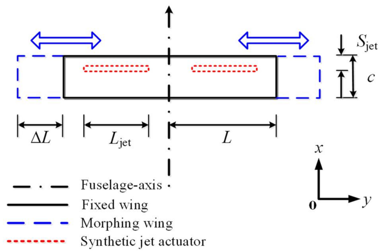
2.1. Description of the Model

To address the poor control efficiency of an aileron at a high AoA, SJA and the morphing span are proposed to achieve the roll control of aircraft. The structural model of morphing aircraft with arrays of actuators is shown in Figure 1, where the fuselage-axis is the axis of symmetry itself. The morphing wing is installed at the tip of the fixed wing, and SJA is located at the middle of the semi-fixed wing, along the spanwise direction. The lengths of the fixed wing, the morphing wing, and the array of SJA are L = 5 m, ΔL ∈ [0, 1.12 m], and Ljet = 3 m, respectively. The chordwise position of the actuator in this study was set as Sjet = 0.12 m, and the chord length as c = 1 m.

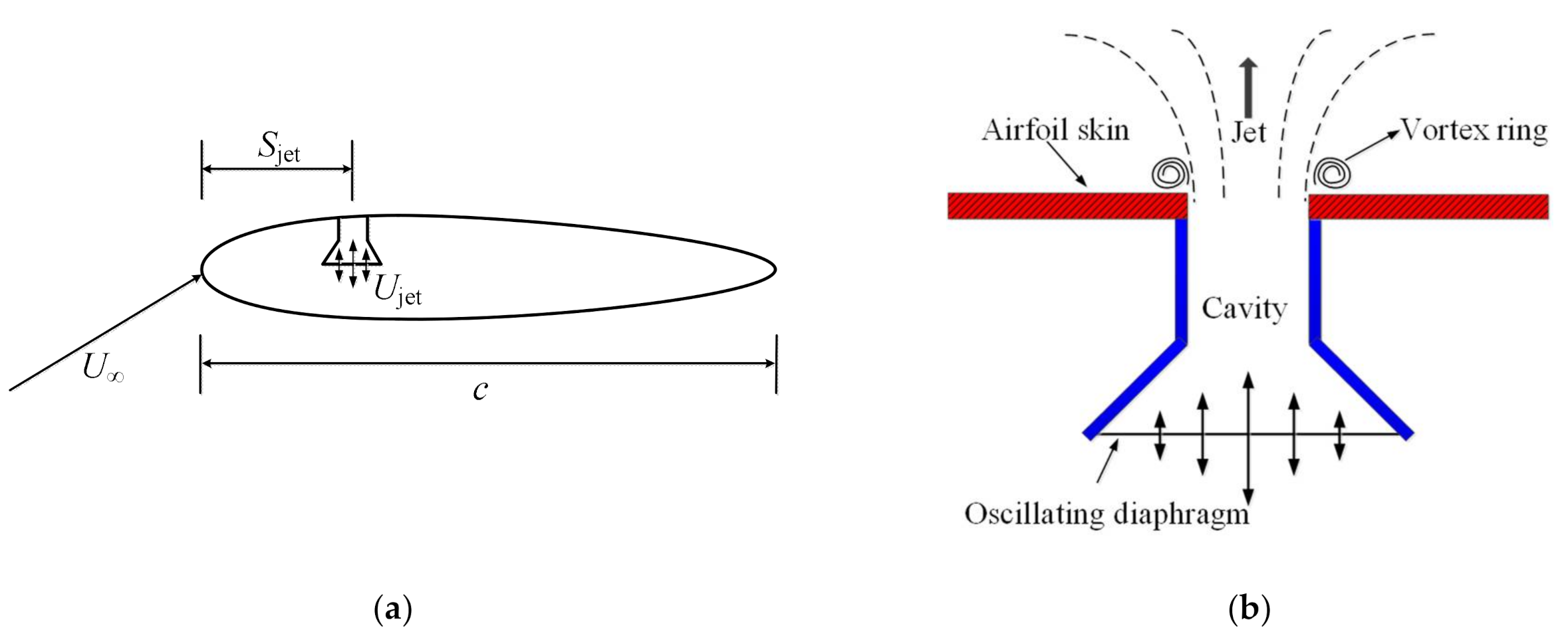
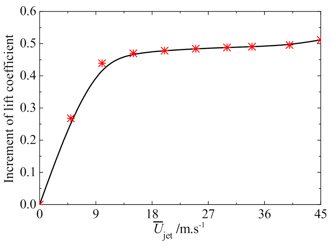
2.2. Modeling for Roll Moment for SJA

To perform the control effect of the SJA, the NACA 0015 airfoil at an 18° AoA shown in Figure 2a was chosen, where Ujet was used to model the blowing/suction type velocity boundary condition at the bottom of the cavity, namely,
U jet = U ¯ jet sin 2 π f t ,
where U ¯ jet is the blowing magnitude and f is the forcing frequency.
A synthetic jet is created by driving the piezoelectric diaphragm at the bottom of the cavity in a periodic manner, as presented in Figure 2b. During oscillation of the membrane, the jet is synthesized and a shear layer is formed by the interaction of pairs of opposite vortex rings at the orifice and the surrounding fluid. The synthetic jet with zero net mass flux, which only requires electrical power, can generate a nonzero momentum [25,26]. Therefore, it can be used for active flow control at a high AoA [27]. Here, an optimized cavity shape with a better performance proposed in our previous work is employed, as shown in Figure 2b [28].
The unsteady aerodynamic force for SJA is calculated by the commercially available code CFD++, which employs the Reynolds-Averaged Navier–Stokes (RANS) equation and Shear Stress Transport (SST) model. The C-grid about the airfoil and the structured mesh of the cavity are generated as shown in Figure 3. To weaken the influence of numerical reflection from the far-field boundary and get a better solution, the computational domain is set as 40 c × 40 c. Furthermore, the meshes near the wall, trailing edge, and cavity are clustered. The widths of the orifice and bottom are 0.52% c and 1.56% c, respectively, and the depth of cavity is 1% c. Let the free stream velocity U be 34 m/s and the Reynolds number Re based on airfoil be 1.9 × 10⁶. The total number of the grid is about 23,000, the height of the first layer of the grid is 10−5 c, and the value of y+ is 0.8 in this study.
In general, the aerodynamic response of synthetic jet-based control is very sensitive to the forcing frequency f, so the aerodynamic lift can be improved by setting the forcing frequency so that it is equal to the vortex-shedding frequency of the airfoil fs, i.e., f = fs = 24.44 Hz in what follows [28]. The effectiveness of synthetic jet-based control is presented in Figure 4, as one can see that the lift coefficient can be increased greatly due to the delay of the separated flow. Here, the free stream velocity and blowing magnitude of the synthetic jet are 34 m/s.
As active flow control, the blowing magnitude U ¯ jet in Equation (1) can be treated as an input for controlling the aerodynamic force. The increment of the lift coefficient for different blowing magnitudes is shown in Figure 5. It indicates that a high blowing magnitude can result in a better aerodynamic performance in the situation of a high AoA.
Due to the effect of roll damping, the AoA of the left (right) wing will decrease (increase) as the aircraft rolls along the positive direction of the fuselage-axis, which will generate a change of roll moment, as follows:
d M x jet = C y l q y d S C y r q y d S + C y , jet l q y d S C y , jet r q y d S = [ k 1 ( α Δ α ) + b k 1 ( α + Δ α ) + b ] q y c d y + C y , jet l q y c d y C y , jet r q y c d y = 2 k 1 Δ α q y c d y + ( C y , jet l δ jet l δ jet l C y , jet r δ jet r δ jet r ) q y c d y = 2 k 1 ω x y U q y c d y + ( C y , jet l δ jet l δ jet l C y , jet r δ jet r δ jet r ) q y c d y ,
where Cy and Cy,jet are roll moment coefficients caused by the rolling motion and SJA, respectively. Here, the coordinate y along the wing span is as shown in Figure 1, and δ jet is the intermediate control input relative to SJA with C y , jet δ jet as coefficients. Subscripts l and r denote the left and right wings, respectively. q = 1 2 ρ air U 2 is the dynamic pressure, S is the surface area of the fixed wing, ωx is the roll angular velocity, and k1 = 0.0258 is a constant when the AoA is around α = 18°. Integrating Equation (2) along the span of the fixed wing gives the roll moment
M x jet = 2 k 1 ω x U q c 0 L y 2 d y + ( C y , jet l δ jet l δ jet l C y , jet r δ jet r δ jet r ) q c 1 5 L 4 5 L y d y = 2 3 k 1 ω x U q c L 3 + 3 10 q c L 2 ( C y , jet l δ jet l δ jet l C y , jet r δ jet r δ jet r ) .
According to Figure 5 and the nonlinear least squares method, one can obtain the relationship between the roll moment coefficient Cy,jet and blowing magnitude U ¯ jet ,
C y , jet = 0.5027 e 0.1766 U ¯ jet + 0.5027 ,
with C y , jet = C y , jet δ jet × δ jet ( 0 , 0.5117 ] , U ¯ jet ( 0 , 45 ] m / s , and δ jet ( 0 , 45 ] m / s . It follows that
C y , jet δ jet = 0.5117 / 45 = 0.0114 .
According to Equations (4) and (5), the relationship between δ jet and U ¯ jet can be obtained, i.e.,
δ jet = C jet / C y , jet δ jet = - 44 . 10 × e 0.1766 U ¯ jet + 44 . 10 .

2.3. Modeling of Roll Moment Due to the Morphing Motion

When the left wing is deployed, the roll moment of the aircraft increases, whereas the roll moment decreases if the right wing is deployed. The change of the roll moment coefficient Δ C y , morphing l due to the morphing of the left wing takes the form
Δ C y , morphing l = k 2 Δ L l ,
where k2 = 0.06466 is a constant calculated by the Tornado Vortex Lattice Method (VLM) [29]. The corresponding change of the roll moment is
Δ M x morphing , l = q Δ S Δ L l Δ C y morphing l = q c k 2 ( Δ L l ) 3 .
Therefore, the total change of the roll moment caused by the morphing motion can be expressed in the following form:
Δ M x morphing = Δ M x morphing , l + Δ M x morphing , r = q c k 2 ( Δ L l ) 3 q c k 2 ( Δ L r ) 3 = q c k 2 δ morphing l q c k 2 δ morphing r ,
where δ morphing is the intermediate input variable of the morphing span.

2.4. Equations of Motion

While the synthetic jet-based control can improve the aerodynamic performance effectively, the fluctuation of the aerodynamic force induced by the periodic excitation of SJA is inevitable, as shown in Figure 4. Notice that the main frequency component of the unsteady response is close to the forcing frequency f, which is equal to fs in this work [28,30]. Based on Equations (3), (6) and (9), the following equations of motion arrive at
M x = M x jet + Δ M x morphing = 47.07 ω x + 60 . 54 δ jet l 60 . 54 δ jet r + 45.78 δ morphing l 45.78 δ morphing r + 804.25 sin 2 π f s t γ ˙ = ω x δ jet = 44 . 10 e 0.1766 U ¯ jet + 44 . 10 δ morphing = ( Δ L ) 3 ,
where Mx is the total roll moment. It is obvious that Equation (10) can be expressed in state space:
x ˙ = A x + B 1 u jet + B 2 u morphing + D sin 2 π f s t ,
with A = 47.07 / J 0 1 0 , B 1 = 60.54 60.54 0 0 / J , B 2 = 45.78 45.78 0 0 / J , x = ω x γ , u jet = δ jet l δ jet r , u morphing = δ morphing l δ morphing r , and D = 804.25 / J 0 , where J = 50 kg·m2 is the moment of inertia.

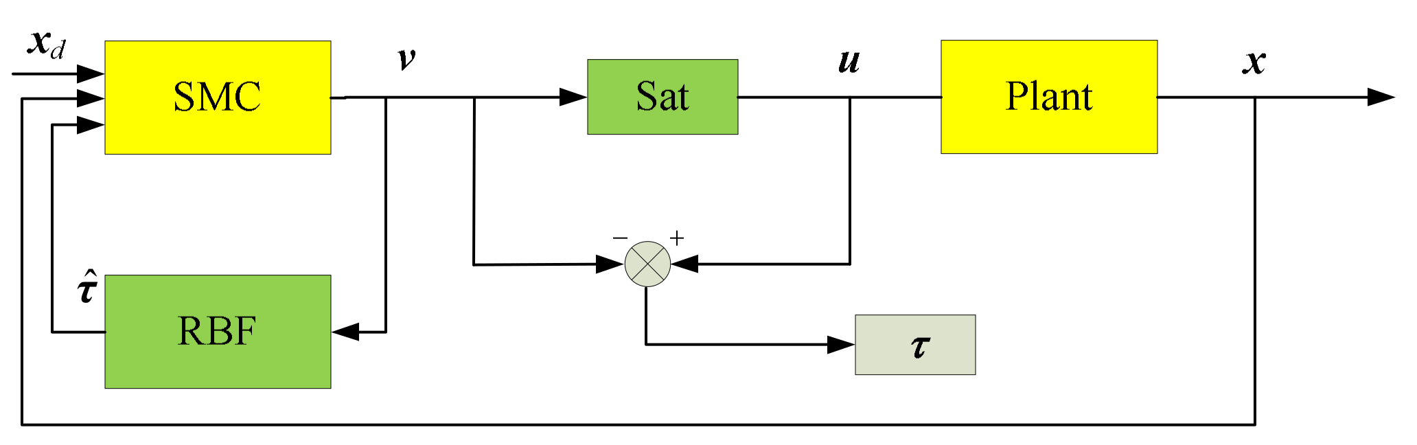
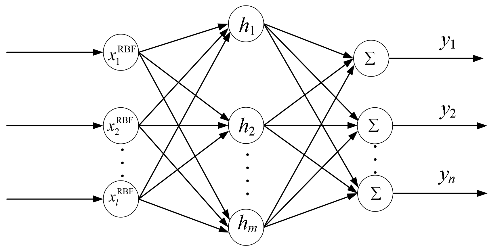
3. Controller Design

In this section, a sliding mode controller [31,32,33] is designed to track the command signal. The structure of the control system is given by Figure 6, wherein the block SMC refers to the Sliding Mode Controller, and the block RBF is employed to provide compensation induced by the input saturation constraint block named Sat.
Take the control purpose as x x d , where xd is the command signal and define the error as e = x x d , then e ˙ = x ˙ x ˙ d . For the tracking problem, the sliding mode function is designed as
s = κ e + e ˙ ,
where κ > 0 . According to the structure of the closed-loop system shown in Figure 6, one has
s ˙ = κ e ˙ + e ¨ = κ e ˙ + x ¨ x ¨ d = κ e ˙ + A x + B u + d t x ¨ d = κ e ˙ + A x + B ( v + τ ) + d t x ¨ d ,
where dt is the fluctuation vector, v is the output of the sliding mode controller, u is the input of the plant, and τ is the error caused by the input saturation constraint.
In this work, the input saturation constraint is considered and compensated for via the RBF neural network so as to approximate the nonlinear function in a compact set with an ideal precision [34,35]. Let xRBF be the input of the RBF neural network, i.e., x RBF = v . Then, based on the structure of the RBF neural network shown in Figure 7, one obtains
τ = W * T h ( v ) + ε ,
where ε i ε max , W * is the ideal weight vector of the linear output neuron, and h is the radial basis function taken to be Gaussian:
h j = exp x RBF c j RBF 2 2 ( b j RBF ) 2 ,
where b j RBF and c j RBF are the radius and center vectors for neuron j.
Taking the estimated output of the RBF neural network as τ ^ = W ^ T h yields
τ τ ^ = W * T h + ε W ^ T h = ( W * T W ^ T ) h + ε = W ¯ T h + ε .
Therefore, the control law is designed as
v = B 1 ( κ e ˙ A x + x ¨ d η sgn ( s ) ) τ ^ ,
where η d t + ε max B .
Substituting Equation (17) into Equation (13) gives the following equation:
s ˙ = η sgn ( s ) + B ( τ τ ^ ) + d t = η sgn ( s ) B W ¯ T h + B ε + d t
A differentiable positive definite function, V, is taken as the Lyapunov function, i.e.,
V = 1 2 s 2 + 1 2 ς W ¯ T W ¯ ,
with ζ > 0. The derivative of the Lyapunov function is
V ˙ = s T s ˙ + ς W ¯ T W ¯ ˙ = η s + s T d t + s T B ( W ¯ T h + ε ) + ς W ¯ T W ¯ ˙ = η s + s T d t + s T B ε + ( s T B W ¯ T h + ς W ¯ T W ¯ ˙ ) .
Let the adaptive law be
W ¯ ˙ = 1 ς ( W ¯ T ) 1 s T B W ¯ T h .
After substituting Equation (21) into Equation (20), one can find
V ˙ = η s + s T ( d t + B ε ) 0 .
It is noted that V ˙ = 0 if and only if s = 0. Therefore, s 0 as t and W ¯ is bounded.

4. Simulation Results and Discussion

The main purpose of this paper is to integrate the innovative combinations of the actuator and advanced active flow control so as to achieve the shape change. In this section, numerical simulations are conducted to perform the control effect of SJA and the morphing span which require that the morphing aircraft follows the desired roll angle command. The parameter values in the third section are given as κ = 5, ζ = 10, η = D + 0.5 , b j RBF = 5 , and c j RBF = 5 × [ 1.0   0.5   0   0.5   1.0 ] . In order to weaken the chattering phenomenon of sliding mode control, the saturation function with a boundary layer thickness of Δ = 2 is employed to replace the sign function in Equation (17).
Several approaches to controlling a large-scale morphing aircraft have been summarized by Seigler, as shown in Figure 8 [36]:
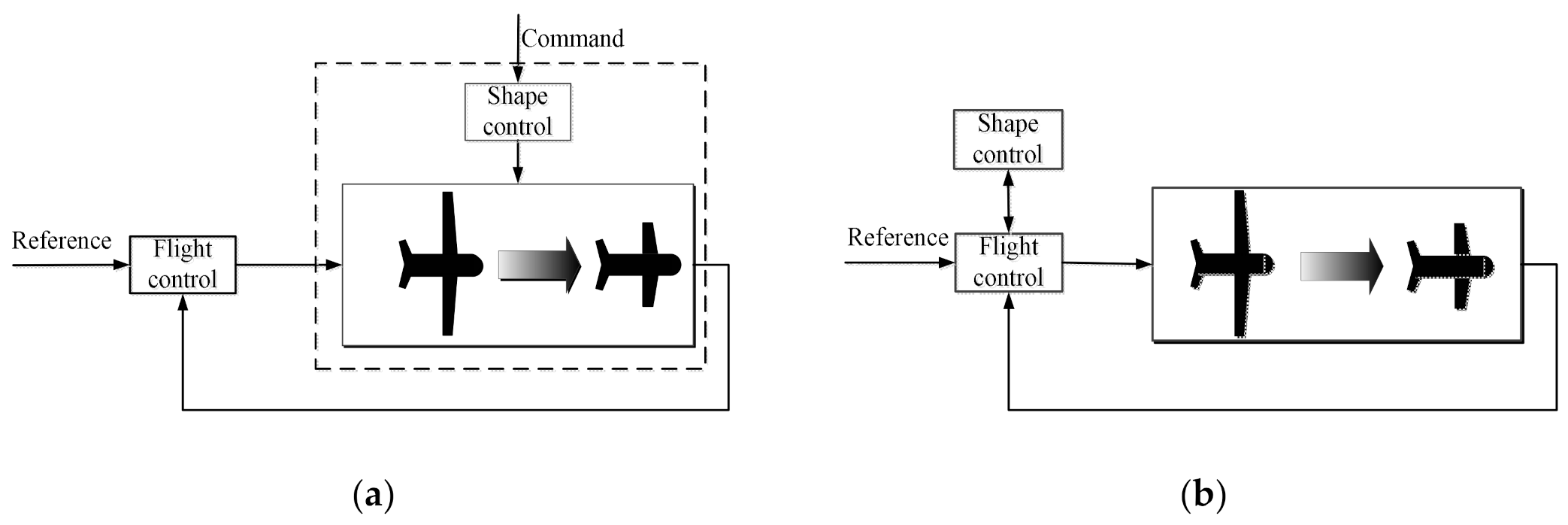
  • The first approach is based on a priori estimate of the long-term vehicle performance, and the shape control operates in an open-manner, which is independent of the instantaneous aircraft state, and
  • The second approach is the integrated shape and flight control, and considers the morphing part as an additional input. Then, the morphing can be achieved by the feedback controller according to the instantaneous state. This method is available in both short-term and long-term maneuvering, and it is the most similar to the bird-like morphing flight found in nature.
In what follows, the two methods are adopted by regarding the morphing span and SJA as virtual control surfaces.

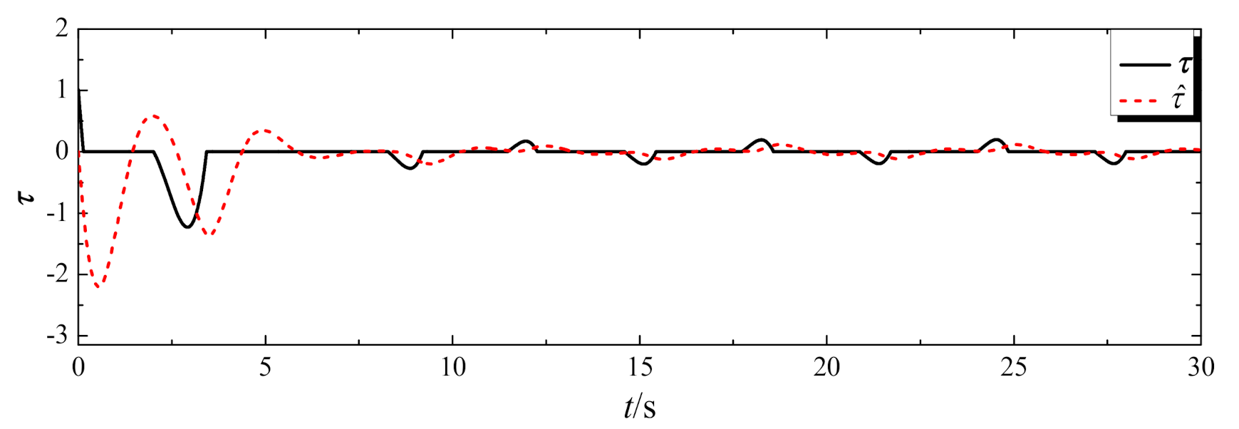
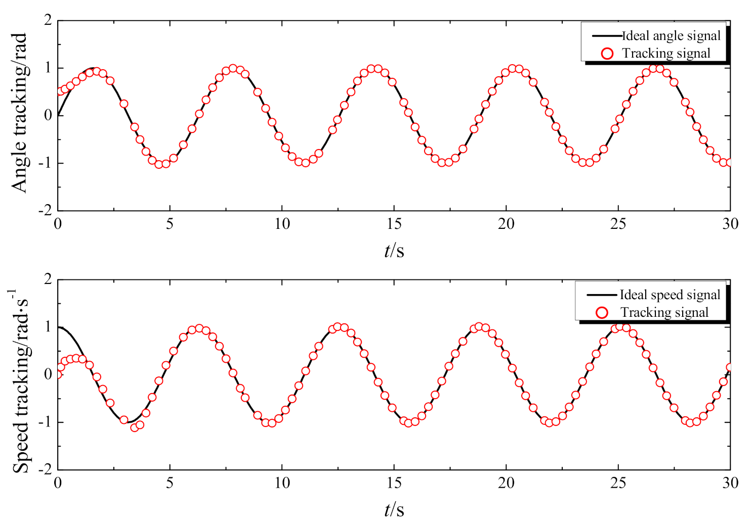
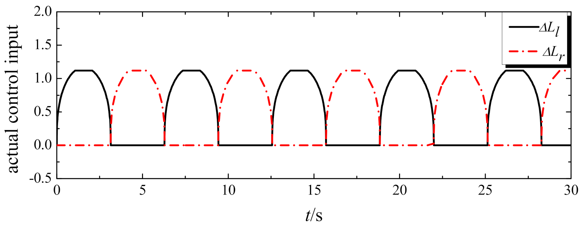
4.1. Roll Controlled by the Morphing Span

In this simulation, the structural change of large-scale morphing is taken as an aerodynamic forcing input determined by the feedback control algorithm, which corresponds to the second approach mentioned. To maintain the roll motion of aircraft by the morphing span only, the input due to SJA is set as δjetl = δjetr = Constant to guarantee the aerodynamic characteristic at a high AoA. The control input of the morphing span with a saturation constraint is depictured in Figure 9. It indicates that the peak value of the input has reached the maximum, with the corresponding compensation by the RBF neural network shown in Figure 10. Figure 11 gives the tracking responses of the angle and speed, with the target angle signal xd = sint. The roll motion is maintained by deploying one side of the wing while keeping the other side alternately stationary. One can see from Figure 11 that although the control input for the morphing span reaches saturation during the roll motion, the RBF neural network can compensate well, and it takes less than 5 s when the roll angle γ matches the reference signal well.

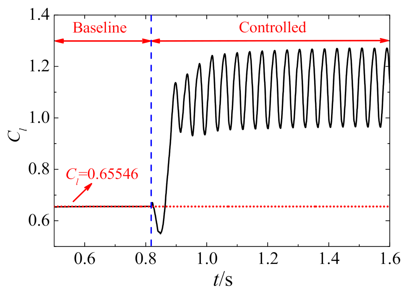
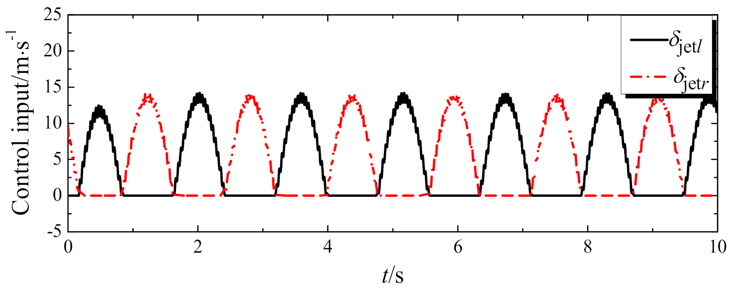
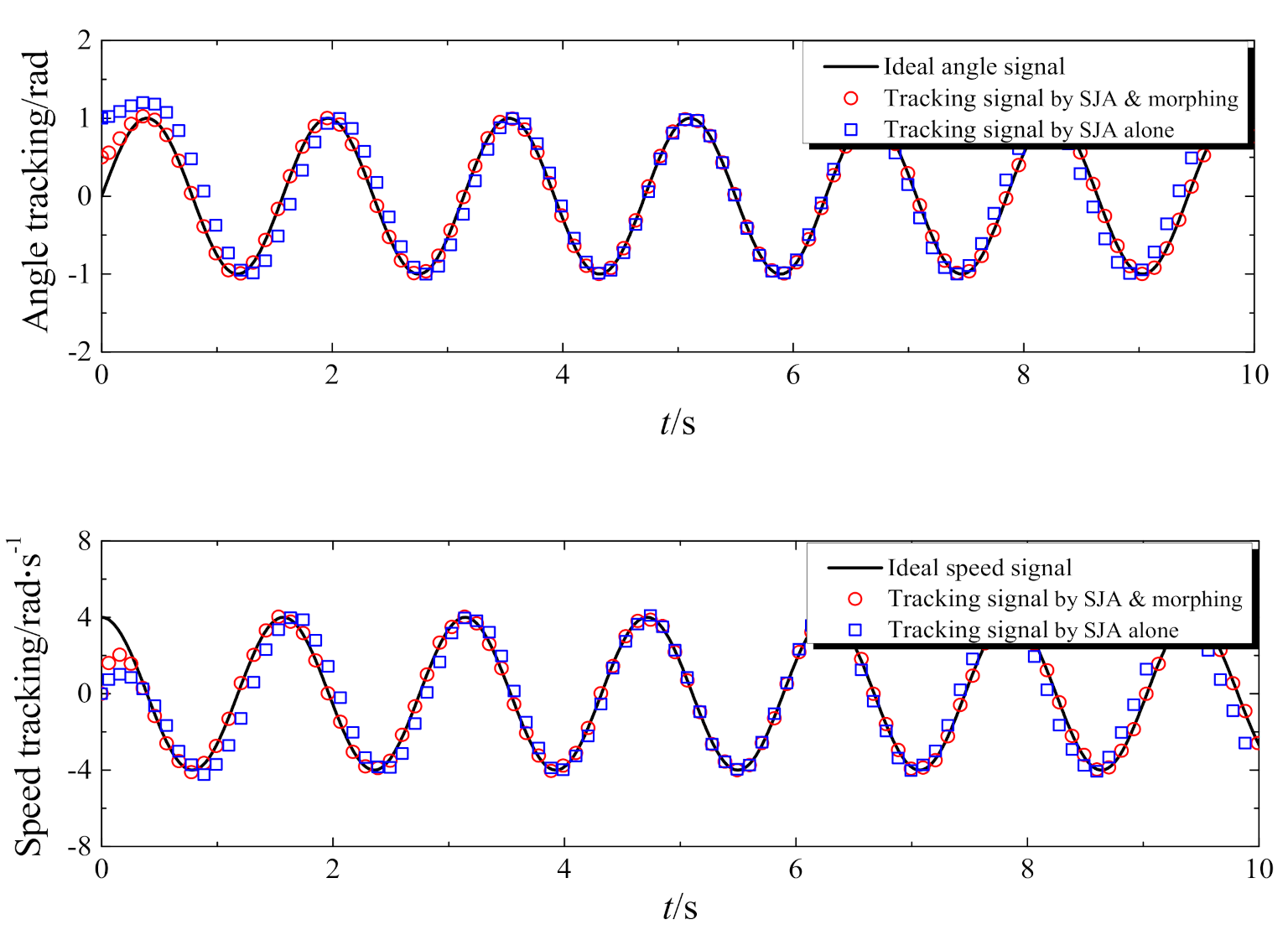
4.2. Roll Controlled by SJA

When the morphing wing of the aircraft is not considered, i.e., ΔL = 0, one can find that the synthetic jet-based control for fixed-wing aircraft can effectively track the command signal of roll motion at a high AoA, as shown in Figure 12 and Figure 13, wherein the reference angle signal is set as xd = sin4t. Furthermore, one can conclude that the controller, which takes approximately 0.5 s to reach stabilization, meets the performance requirement and eliminates the influence of the disturbance induced by SJA.
It has been found that an aircraft’s altitude is only able to be controlled well by SJA; in other words, the system is over-actuated with redundant control when additional control by the morphing span is added, which means that control due to the morphing wing can be treated as an auxiliary tool that can be properly allocated [37]. On the other hand, the morphing span can also be considered the controlled object, i.e., the roll motion of aircraft with a preplanned morphing strategy (e.g., Equation (23) and Figure 14) can be controlled via the SJA, which belongs to the first control approach for large-scale morphing aircraft.
δ morphing = 1.4 , δ morphing 1 . 4   1.6 sin t , δ morphing < 1 . 4  
The tracking responses obtained via SJA and the morphing wing are shown in Figure 13. One can see from Figure 13 that the reference signal can be tracked perfectly. Especially when compared with the case controlled by SJA alone, the redundant control input due to morphing can make the tracking response converge to the target more quickly. In addition, the span extends asymmetrically and the curve of morphing in Figure 14 is quite smooth, such that the flight stability during the morphing motion can be guaranteed [5,38].

5. Conclusions

Active flow control and sliding mode control have been integrated together to tackle the problem of modeling and control morphing aircraft at a high AoA. The dynamic model has been established with a consideration of roll damping, the morphing motion, and aerodynamic fluctuation induced by SJA. The synthetic jet technique with an optimized cavity shape has not only been used to improve the aerodynamic performance of aircraft at a high AoA, but also to execute flight control along with the morphing span. The simulation results show that the proposed control strategy for roll control could track the command signal quickly and effectively. Furthermore, the roll motion associated with a given morphing strategy could be maintained via SJA, and the following conclusions can be obtained:
  • The roll dynamic with a low frequency of morphing aircraft can be controlled by the morphing motion, which can track the ideal response within a few seconds, and
  • By introducing active flow control based on SJA, roll motion with a higher frequency at a high AOA can be controlled within a fraction of a second, and an additional redundant controlled input provided by motion morphing will be conducive to improving the control performance of the system.

Author Contributions

Conceptualization, W.L. and W.W.; methodology, W.L.; software, W.W.; validation, S.Z. and W.L.; investigation, S.Z.; data curation, S.Z.; writing—original draft preparation, W.W.; writing—review and editing, X.H., C.L. and W.L.; funding acquisition, W.L. All authors have read and agreed to the published version of the manuscript.

Funding

This work was supported by the Fundamental Research Funds for the Central Universities (2662018QD029), the Natural Science Foundation of Hubei Province of China (2020CFB309), and the Key Research and Development Program of Hubei Province of China (2020BBB062).

Data Availability Statement

Please contact the authors for the raw/processed data required to reproduce these findings.

Acknowledgments

The authors would like to thank Kun Xie and Wanjing Dong of Huazhong Agricultural University for their contributions to this work.

Conflicts of Interest

The authors declare no conflict of interest.

References

  1. Huang, R.; Yang, Z.; Yao, X.; Zhao, Y.; Hu, H. Parameterized Modeling Methodology for Efficient Aeroservoelastic Analysis of a Morphing Wing. AIAA J. 2019, 57, 5543–5552. [Google Scholar] [CrossRef]
  2. Yue, T.; Zhang, X.; Wang, L.; Ai, J. Flight Dynamic Modeling and Control for a Telescopic Wing Morphing Aircraft via Asymmetric Wing Morphing. Aerosp. Sci. Technol. 2017, 70, 328–338. [Google Scholar] [CrossRef]
  3. Zhao, Y.; Hu, H. Prediction of Transient Responses of a Folding Wing during the Morphing Process. Aerosp. Sci. Technol. 2013, 24, 89–94. [Google Scholar] [CrossRef]
  4. Weisshaar, T.A. Morphing Aircraft Systems: Historical Perspectives and Future Challenges. J. Aircr. 2013, 50, 337–353. [Google Scholar] [CrossRef]
  5. Seigler, T.M.; Neal, D.A. Analysis of Transition Stability for Morphing Aircraft. J. Guid. Control Dyn. 2009, 32, 1947–1954. [Google Scholar] [CrossRef]
  6. Huang, R.; Zhao, Y.; Hu, H. Wind-Tunnel Tests for Active Flutter Control and Closed-Loop Flutter Identification. AIAA J. 2016, 54, 2089–2099. [Google Scholar] [CrossRef]
  7. Waszak, M.R. Robust Multivariable Flutter Suppression for Benchmark Active Control Technology Wind-Tunnel. Model. J. Guid. Control Dyn. 2001, 24, 147–153. [Google Scholar] [CrossRef]
  8. Huang, R.; Hu, H.; Zhao, Y. Single-Input/Single-Output Adaptive Flutter Suppression of a Three-Dimensional Aeroelastic System. J. Guid. Control Dyn. 2015, 35, 659–665. [Google Scholar] [CrossRef]
  9. Wang, Y.; Xu, J.; Huang, S.; Lin, Y.; Jiang, J. Computational Study of Axisymmetric Divergent Bypass Dual Throat Nozzle. Aerosp. Sci. Technol. 2019, 86, 177–190. [Google Scholar] [CrossRef]
  10. Cassaro, M.; Battipede, M.; Marzocca, P.; Behal, A. Comparison of Adaptive Control Architectures for Flutter Suppression. J. Guid. Control Dyn. 2015, 38, 346–355. [Google Scholar] [CrossRef] [Green Version]
  11. Ben-Asher, J.Z.; Cohen, K.; Adin, Z.; Moulin, B.; Weller, T. Flutter Supression Using Linear Optimal and Fuzzy Logic Techniques. J. Guid. Control Dyn. 2003, 26, 173–177. [Google Scholar] [CrossRef]
  12. Luo, M.; Gao, M.; Cai, G. Delayed Full-State Feedback Control of Airfoil Flutter Using Sliding Mode Control Method. J. Fluids Struct. 2016, 61, 262–273. [Google Scholar] [CrossRef]
  13. Huang, R.; Qian, W.; Hu, H.; Zhao, Y. Design of Active Flutter Suppression and Wind-Tunnel Tests of a Wing Model Involving a Control Delay. J. Fluids Struct. 2015, 55, 409–427. [Google Scholar] [CrossRef]
  14. Shi, R.; Peng, J. Morphing Strategy Design for Variable-Wing Aircraft. In Proceedings of the 15th AIAA Aviation Technology, Integration, and Operations Conference, Dallas, TX, USA, 22–26 June 2015. [Google Scholar]
  15. Henry, J.; Pines, D.A. Mathematical Model for Roll Dynamics by Use of a Morphing-Span Wing. In Proceedings of the 48th AIAA/ASME/ASCE/AHS/ASC Structures, Structural Dynamics, and Materials Conference, Honolulu, HI, USA, 23–26 April 2007. [Google Scholar]
  16. Ajaj, R.M.; Friswell, M.I. Aeroelasticity of Compliant Span Morphing Wings. Smart Mater. Struct. 2018, 27, 105052. [Google Scholar] [CrossRef] [Green Version]
  17. Ajaj, R.M.; Friswell, M.I.; Flores, E.I.S.; Isikveren, A.T.; Allegri, G.; Adhikari, S.; Chaouk, H. An Integrated Conceptual Design Study Using Span Morphing Technology. J. Intell. Mater. Syst. Struct. 2013, 25, 989–1008. [Google Scholar] [CrossRef]
  18. Ajaj, R.M.; Friswell, M.; Flores, E.I.S.; Isikveren, A.T.; Little, O. Span Morphing: A Conceptual Design Study. In Proceedings of the 20th AIAA/ASME/AHS Adaptive Structures Conference, Honolulu, HI, USA, 23–26 April 2012. [Google Scholar]
  19. Barbarino, S.; Bilgen, O.; Ajaj, R.M.; Friswell, M.I.; Inman, D.J. A Review of Morphing Aircraft. J. Intell. Mater. Syst. Struct. 2011, 22, 823–877. [Google Scholar] [CrossRef]
  20. Mcgowan, A.R.; Waszak, M.R. NASA’s Morphing Project Research Summaries in Fiscal Year 2002. 2005. Available online: https://ntrs.nasa.gov/api/citations/20050137467/downloads/20050137467.pdf (accessed on 18 December 2020).
  21. Zhao, G.; Zhao, Q. Parametric Analyses for Synthetic Jet Control on Separation and Stall over Rotor Airfoil. Chin. J. Aeronaut. 2014, 27, 1051–1061. [Google Scholar] [CrossRef] [Green Version]
  22. Deb, D.; Tao, G.; Burkholder, J.O.; Smith, D.R. Adaptive Compensation Control of Synthetic Jet Actuator Arrays for Airfoil Virtual Shaping. J. Aircr. 2007, 44, 616–626. [Google Scholar] [CrossRef]
  23. Wei, Q.; Niu, Z.; Chen, B.; Huang, X. Bang-Bang Control Applied in Airfoil Roll Control with Plasma Actuators. J. Aircr. 2013, 50, 670–677. [Google Scholar] [CrossRef] [Green Version]
  24. Li, C.; Yang, J. Roll Control Using Only Synthetic Jet Actuators at High Angle of Attack. J. Aircr. 2017, 54, 369–375. [Google Scholar] [CrossRef]
  25. Li, J.; Zhang, X. Active Flow Control for Supersonic Aircraft: A Novel Hybrid Synthetic Jet Actuator. Sens. Actuators A Phys. 2020, 302, 111770. [Google Scholar] [CrossRef]
  26. He, W.; Luo, Z.; Deng, X.; Peng, W.Q.; Zhao, Z. Experimental Investigation on the Vectoring Spray Based on a Novel Synthetic Jet Actuator. Appl. Therm. Eng. 2020, 179, 115677. [Google Scholar] [CrossRef]
  27. Xu, X.; Zhou, Z. Study on Longitudinal Stability Improvement of Flying Wing Aircraft Based on Synthetic Jet Flow Control. Aerosp. Sci. Technol. 2015, 46, 287–298. [Google Scholar] [CrossRef]
  28. Li, W.; Jin, D.; Zhao, Y. Efficient Nonlinear Reduced-Order Modeling for Synthetic-Jet-Based Control at High Angle of Attack. Aerosp. Sci. Technol. 2017, 62, 98–107. [Google Scholar] [CrossRef]
  29. Melin, T. A Vortex Lattice Matlab Implementation for Linear Aerodynamic Wing Applications; Royal Institute of Technology: Stockholm, Sweden, 2000. [Google Scholar]
  30. He, Y.; Cary, A.; Peters, D. Parametric and Dynamic Modeling for Synthetic Jet Control of a Post-stall Airfoil. In Proceedings of the 39th Aerospace Sciences Meeting and Exhibit, Reno, NV, USA, 8–11 January 2001. [Google Scholar]
  31. Dahech, K.; Allouche, M.; Damak, T.; Tadeo, F. Backstepping Sliding Mode Control for Maximum Power Point Tracking of a Photovoltaic System. Electr. Power Syst. Res. 2017, 143, 182–188. [Google Scholar] [CrossRef]
  32. Efimov, D.; Polyakov, A.; Fridman, L.; Perruquetti, W.; Richard, J.P. Delayed Sliding Mode Control. Automatica 2016, 64, 37–43. [Google Scholar] [CrossRef] [Green Version]
  33. Liu, J. Radial Basis Function (RBF) Neural Network Control for Mechanical Systems Neural Network Sliding Mode Control; Tsinghua University Press: Beijing, China, 2013. [Google Scholar]
  34. Bradley, J.B. Neural Networks: A Comprehensive Foundation. Inf. Process. Manag. 1995, 31, 786. [Google Scholar] [CrossRef]
  35. Zhang, W.; Wang, B.; Ye, Z.; Quan, J. Efficient Method for Limit Cycle Flutter Analysis Based on Nonlinear Aerodynamic Reduced-Order Models. AIAA J. 2012, 50, 1019–1028. [Google Scholar] [CrossRef]
  36. Seigler, T.M.; Neal, D.A.; Bae, J.; Inman, D.J. Modeling and Flight Control of Large-Scale Morphing Aircraft. J. Aircr. 2007, 44, 1077–1087. [Google Scholar] [CrossRef]
  37. Valasek, M. Design and Control of Under-actuated and over-Actuated Mechanical Systems: Challenges of Mechanics and Mechatronics. Veh. Syst. Dyn. 2003, 40, 37–49. [Google Scholar]
  38. Shi, R.; Wan, W. Analysis of Flight Dynamics for Large-Scale Morphing Aircraft. Aircr. Eng. Aerosp. Technol. 2015, 87, 38–44. [Google Scholar] [CrossRef]
Figure 1. Top view of morphing aircraft with a synthetic jet actuator (SJA).
Applsci 11 00505 g001
Figure 2. Side view of the morphing wing. (a) Synthetic jet-based airfoil and (b) synthetic jet actuator.
Applsci 11 00505 g002
Figure 3. The mesh around NACA 0015 airfoil. (a) C-grid detail and (b) zoomed-in view near the cavity.
Applsci 11 00505 g003
Figure 4. The effectiveness of synthetic jet-based control [28].
Applsci 11 00505 g004
Figure 5. The influence of the blowing magnitude on the lift coefficient.
Applsci 11 00505 g005
Figure 6. Structure of the closed-loop system.
Applsci 11 00505 g006
Figure 7. Structure of the Radial Basis Function (RBF) neural network.
Applsci 11 00505 g007
Figure 8. Different methods for flight control of morphing aircraft. (a) Independent shape and flight control and (b) integrated shape and flight control.
Applsci 11 00505 g008
Figure 9. The control input due to morphing motion.
Applsci 11 00505 g009
Figure 10. Compensation of the RBF neural network.
Applsci 11 00505 g010
Figure 11. Angle and speed tracking response.
Applsci 11 00505 g011
Figure 12. The intermediate control input due to SJA.
Applsci 11 00505 g012
Figure 13. Angle and speed tracking response.
Applsci 11 00505 g013
Figure 14. The actual control input due to the morphing motion.
Applsci 11 00505 g014
Publisher’s Note: MDPI stays neutral with regard to jurisdictional claims in published maps and institutional affiliations.

