Article

Experimental and Numerical Studies on the Structural Performance of a Double Composite Wall

1
Department of Architectural Engineering, University of Seoul, 163 Seoulsiripdaero, Dongdaemun-gu, Seoul 02504, Korea
2
Department of Architectural Engineering and Smart City Interdisciplinary Major Program, University of Seoul, 163 Seoulsiripdaero, Dongdaemun-gu, Seoul 02504, Korea
3
Department of Medical Space Design & Management, Konyang University, 158 Gwanjeodong-ro, Seo-gu, Daejeon 35365, Korea
*
Author to whom correspondence should be addressed.
Appl. Sci. 2021, 11(2), 506; https://doi.org/10.3390/app11020506
Submission received: 11 December 2020 / Revised: 30 December 2020 / Accepted: 1 January 2021 / Published: 6 January 2021

Abstract

:
In this study, experiments and numerical analyses were carried out to examine the flexural and shear performance of a double composite wall (DCW) manufactured using a precast concrete (PC) method. One flexural specimen and three shear specimens were fabricated, and the effect of the bolts used for the assembly of the PC panels on the shear strength of the DCW was investigated. The failure mode, flexural and shear behavior, and composite behavior of the PC panel and cast-in-place (CIP) concrete were analyzed in detail, and the behavioral characteristics of the DCW were clearly identified by comparing the results of tests with those obtained from a non-linear flexural analysis and finite element analysis. Based on the test and analysis results, this study proposed a practical equation for reasonably estimating the shear strength of a DCW section composed of PC, CIP concrete, and bolts utilizing the current code equations.

1. Introduction

The precast concrete (PC) method has been widely used in the construction of underground parking lots, logistics warehouses, and semiconductor fabrication plants to achieve rapid construction [1,2,3]. Especially in the case of semiconductor plant construction, underground work needs to be conducted to secure spaces for large-scale facilities, such as purification systems; thus, a basement wall with a height of 10 m or more is built [4]. If a reinforced concrete (RC) method is applied to the basement wall, the construction period may be significantly delayed because it requires temporary work and concrete curing time to ensure the required strength. For this reason, research has been continuously carried out on the development of a PC composite wall capable of facilitating the quality control of concrete and decreasing the construction period [5,6,7].
Moon and Choi [5] and Ji and Choi [6] developed a mega double wall (MDW) in which two PC panels were connected by a concrete link beam and in-filled concrete was poured into the hollow part; they then conducted an experimental verification of its structural performance. Kim et al. [7] developed a precast concrete double wall (PCDW) where internal and external PC panels are connected with a truss-shaped reinforcement, and proposed a design method for the field application of PCDW. In addition, Kim et al. performed a detailed comparative analysis of the constructability and economic efficiency of PCDW and RC walls. McKinley and Boswell [8], Ji et al. [9], and Qin et al. [10] conducted experimental and analytical studies on double skin composite PC walls that can ensure high strength and stiffness, and Holden et al. [11], Nie et al. [12], Yamamura and Kiyomiya [13], and Hilo et al. [14] performed research to investigate the structural performance of concrete walls strengthened with steel members. In particular, Yamamura and Kiyomiya [13] proposed a shear strengthening method in which reinforcing bars are inserted after perforating the basement wall. They verified through experiments and finite element analysis that the wall with the reinforcing bars inserted shows a greater than 80% increase in shear strength compared with the existing walls without shear reinforcement.
Meanwhile, in South Korea a double composite wall (DCW) system—a new type of basement wall, as shown in Figure 1—was developed [4], and it has been actively applied in construction sites since then. The DCW is completed by pouring cast-in-place (CIP) concrete after assembling two prefabricated PC panels with bolts in a factory. The DCW has an advantage in that it provides excellent constructability because two PC panels are simply connected together by bolts, which also ensures a high level of safety, as the lateral pressure that occurs while pouring CIP concrete is controlled through the bearing stress at the bolted connection. Moreover, because the assembled PC panel plays a role as a formwork, additional temporary works are not required when CIP concrete is cast into the hollow section. The shear key of the PC panel not only facilitates assembly, but also makes an effective contribution to the horizontal shear resistance mechanism after the CIP concrete composite. Figure 2 shows the sequence of the actual construction process for the DCW system. First, PC panels are produced in a PC factory, and two panels are assembled with bolts, as shown in Figure 2d. Subsequently, the assembled PC panel is installed on the foundation, and CIP concrete is then poured into the hollow part to complete the DCW. When a bending moment acts on the DCW, dowel bars embedded in the foundation resist tensile force at the foundation–wall connection, as shown in Figure 1, while reinforcing bars placed on the flange of the PC panel resist tensile force at the center and top of the wall.
Regarding the shear design of the DCW, as the CIP concrete accounts for greater than 60% of the cross-sectional area of the DCW, in practice the entire section is considered to be CIP concrete to derive the design results on the safe side in a simple manner. Moreover, the shear contribution of the bolts used for assembling the PC panels is not considered in the estimation of shear strength. That is, only the shear contribution of the CIP concrete ( V c , C I P ) is taken into account in the shear design of the DCW.
However, in this case excessively conservative design results can be obtained because the characteristics of the PC panel to which concrete with a compressive strength greater than 40 MPa is applied and the shear contribution of the bolts are not reflected.
In this study, experiments and numerical analysis were performed to clearly identify the flexural and shear performances of DCW, which have not been investigated in detail elsewhere before. To this end, one flexural specimen and three shear specimens were fabricated, and the presence of bolts for assembling the PC panels was set as the main variable in the shear test. To analyze the flexural and shear behaviors of the DCW in detail, strain gauges were attached to the concrete surface, reinforcing bars, and bolts, and the slip between the PC panel and the CIP concrete was measured. Note that strain gages with a gage length of 60 mm were used for concrete, and those with a gage length of 5 mm were applied to the reinforcing bars and bolts. In addition, a non-linear flexural analysis and a finite element analysis were conducted, and the analysis and test results were then compared in detail.

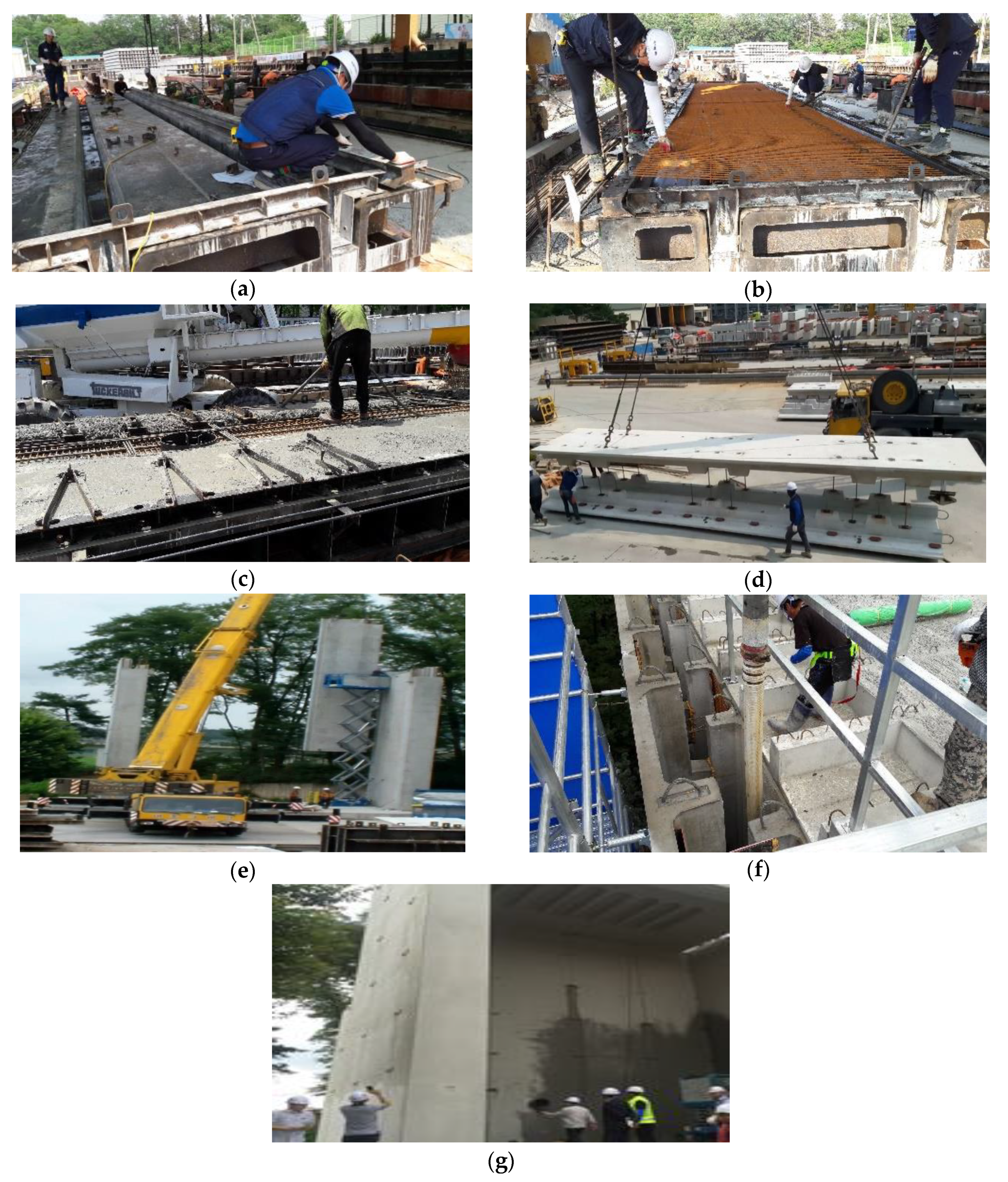
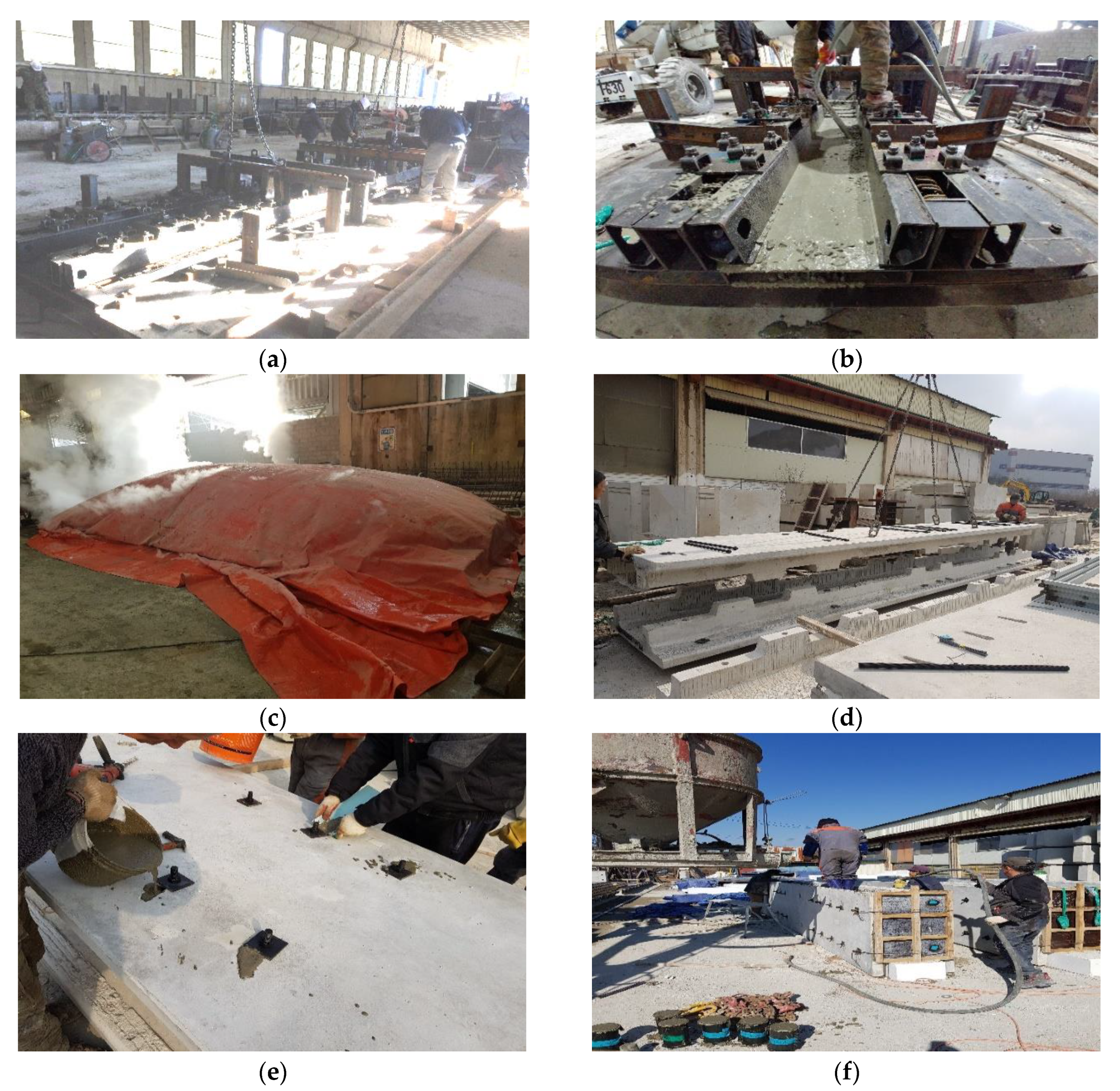
2. Experimental Program

2.1. Test Specimens

Table 1 and Figure 3 show the section details and material properties of the DCW specimens. All the test specimens were fabricated at a 1/2 actual scale, which was determined based on the limitation of experimental testing facilities for this study, and the PC panel had a width ( b ) of 1190 mm and a length ( L ) of 7300 mm. Inside the PC flange, 13 reinforcing bars with a diameter of 19 mm were placed, and distribution bars with a diameter of 10 mm were arranged at intervals of 150 mm. In addition, stirrups were laid inside the shear keys to control the localized cracks that may occur during the lifting and assembly of PC panels. In the flexural specimen DCW-F and the shear specimens DCW-SB(1) and (2), bolts were used to assemble the PC panels at the both ends and at the center of the member. On the other hand, no bolts were placed in the shear span of the DCW-SN specimen. Note that the shear contribution of bolts used to assemble the PC panels can be obtained by comparing the shear strength of the DCW-SN specimen and that of the DCW-SB specimens. For the DCW-F specimen, 10 mm-diameter stirrups were placed in the hollow part at 150 mm intervals to prevent shear failure during the experiment. The yield strengths of the D19 and D10 bars ( f y and f v y ) used in the specimen fabrication were 625 and 591 MPa, respectively, and the yield strength of the bolt ( f y b ) used for assembling the PC panels was 476 MPa.
Figure 4 shows the fabrication process of the DCW specimens. First, concrete was poured and subjected to steam curing for one day, and a 6 mm-deep rough surface treatment was applied on the upper surface of the PC panel in accordance with the ACI 318 code [15] to ensure the composite performance with CIP concrete. After this, the PC panels were assembled using bolts, grout was injected into the bolt holes, and CIP concrete was poured into the hollowed section to complete the specimen fabrication. The specimens were then cured in the atmosphere for 28 days. The concrete compressive strength of the PC panel ( f c , P C ) ranged from 40.2 to 42.6 MPa, and that of the CIP concrete ( f c , C I P ) was 23.5 MPa. As shown in Figure 5, the DCW-F specimen was subjected to two-point loads with a shear span to depth ratio ( a / d s ) of 5.45. The lengths of the left and right shear spans of the DCW-SN and DCW-SB specimens were set at different values to induce shear failure within the target shear span. The specimens were loaded using a universal testing machine with a capacity of 5000 kN. In order to measure the deflections of the specimens, linear variable differential transformers (LVDTs) were installed at the mid-span of the flexural specimen and at the loading point of the shear specimen, and an additional LVDT was installed at the end of the member to measure the slip between the PC panel and CIP concrete.

2.2. Test Results

Figure 6a shows the flexural behavior of the DCW-F specimen. The vertical axis of the graph represents the total loads acting on the specimen. The first flexural cracking occurred near the loading point at a load of 66 kN, and cracking between the shear keys of the upper and lower panels was observed at a load of 333 kN. The strain of tensile reinforcement reached the yield strain ( ε y ) at a load of 739 kN. Afterward, the specimen exhibited ductile behavior and then underwent flexural failure due to the crushing of concrete at the extreme compression fiber near the loading point at a load of 894 kN. As shown in Figure 6b, the position of the neutral axis increased as the load increased in the section located at the mid-span, and the strain of the tensile reinforcement increased sufficiently by 1.0 × 10 4   μ ε or more at the ultimate load. Figure 6c shows the measured end slip between the PC panel and the CIP concrete at the end of the DCW-F specimen, and the maximum slip observed during the test was only 0.02 mm. If it is assumed that the strain difference ( Δ ε c ) at the interface between the PC panel and the CIP concrete is uniformly distributed over the longitudinal direction from the support to the loading point, the average strain difference Δ ε c , a v g can be calculated as follows:
Δ ε c , a v g = ε c i , P C ε c i , C I P = s e a ,
where ε c i , P C and ε c i , C I P are the strains of the PC panel and CIP concrete at the interface, respectively; s e is the end slip; and a is the length of the shear span. The difference in strain ( Δ ε c , a v g ) between the PC panel and CIP concrete was calculated to be 6.5   μ ε , which is so small that it can be considered negligible. Therefore, in the following section it was assumed that in the nonlinear flexural analysis of the DCW-F specimen, the PC panel and the CIP concrete are in a fully composite state [16].
Figure 7 shows the shear test results of the DCW-S specimen series. The vertical axis of the graphs represents the shear force acting on the specimen in the intended shear failure region—i.e., the end region. In the DCW-SN specimen, where bolts for assembling PC panels were not placed in the shear span, the first flexural cracking occurred near the loading point at a shear force of approximately 160 kN, as shown in Figure 7a. The stiffness of the specimen began to decrease when inclined cracking was observed at a shear force of 367 kN. In addition, cracking between the shear keys in the upper and lower PC panels occurred at a shear force of 527 kN, and web-shear cracking was observed near the support at a shear force of 607 kN. Even after this, the load continued to increase, and the specimen failed in shear at a shear force of 719 kN. Regarding the DCW-SN specimen, it was found that shear cracks that occurred in the lower PC panel could not propagate to the upper PC panel; rather, the crack developed along the shear key interface. Nevertheless, since the rough surface finishing of the PC panel was applied and the shear keys of the upper and lower panels were interlocked with each other, the maximum end slip was only 0.03 mm, as shown in Figure 7d.
For the DCW-SB(1) specimen in which bolts were placed in the shear span, as shown in Figure 7b, flexural cracking occurred at a shear force of about 160 kN, and shear cracking was observed at a shear force of 389 kN. In the upper surface of the bottom flange, horizontal cracking toward the support occurred at a shear force of 607 kN, as shown in the picture in Figure 7b, and the stiffness of the specimen began to decrease rapidly, starting from a shear force of approximately 900 kN. Finally, after reaching the maximum shear force of 950 kN, the DCW-SB(1) specimen underwent failure as the load gradually decreased. In the DCW-SB(2) specimen with the same details as the DCW-SB(1) specimen, the first flexural cracking was observed at a shear force of 158 kN, and inclined cracking occurred at a shear force of 467 kN, as shown in Figure 7c. After that, the DCW-SB(2) specimen showed behavior that was almost similar to that of the DCW-SB(1) specimen and failed in shear at a shear force of 947 kN. It should be noted that in the DCW-SB(1) and (2) specimens, shear cracks that occurred in the lower PC panel propagated to the upper PC panel, unlike in the DCW-SN specimen, because the integrity of the upper and lower PC panels was improved due to the bolts placed in the shear span. Consequently, the shear strengths of the DCW-SB(1) and (2) specimens increased by about 32% compared with those of the DCW-SN specimen because of the shear contribution of the bolts used for assembling the PC panels.
Figure 7e shows the axial strains measured from the gauges attached to the bolts placed in the DCW-SB(1) specimen. Although the bolts placed in the shear span contributed considerably to the shear resistance mechanism of the member, the yield strain was not reached until the maximum load. Therefore, based on the measured bolt strains, this study sought to make a quantitative approach to determine the contribution of concrete and bolts in the DCW member, as shown in Figure 8. The shear contribution of the bolts ( V b o l t ) was estimated as shown below.
V b o l t = A b v ε b o l t E b o l t d s s b v   ( when   ε b o l t ε y , b o l t ) ,
V b o l t = A b v f y b d s s b v   ( when   ε b o l t > ε y , b o l t ) ,
where ε b o l t is the measured bolt strain from the shear test; E b o l t is the elastic modulus of the bolt, which is 149 GPa; A b v is the sectional area of the bolt; ε y , b o l t and f y b are the yield strain and stress of the bolt, respectively; and s b v is the bolt spacing. In the DCW-SB(1) specimen, the shear contribution of concrete ( V c ) was calculated by excluding the shear contribution of bolts ( V b o l t ) from the total shear force acting on the member. As a result, it was found that concrete resisted most of the external shear force at the early stages of the DCW-SB(1) specimen behavior, and bolts began to contribute to the shear resistance after the inclined shear cracking. The bolt contribution ( V b o l t ) at the ultimate strength of the member was approximately 1/3 of the total shear force. In addition, when the shear strength was reached the shear contribution of the concrete ( V c ) of the DCW-SB(1) specimen was smaller than that of the DCW-SN specimen without bolts. This is because the DCW-SB(1) specimen exhibited a greater deformation capacity because of the shear contribution of the bolt; thus, the width of the critical shear crack generated in the DCW-SB(1) specimen at the ultimate state was larger than that of the DCW-SN specimen. Note that the maximum shear crack width observed in the DCW-SB(1) specimen before shear failure was 0.9 mm, while the maximum shear crack width in the DCW-SN specimen was 0.4 mm.

3. Numerical Approach

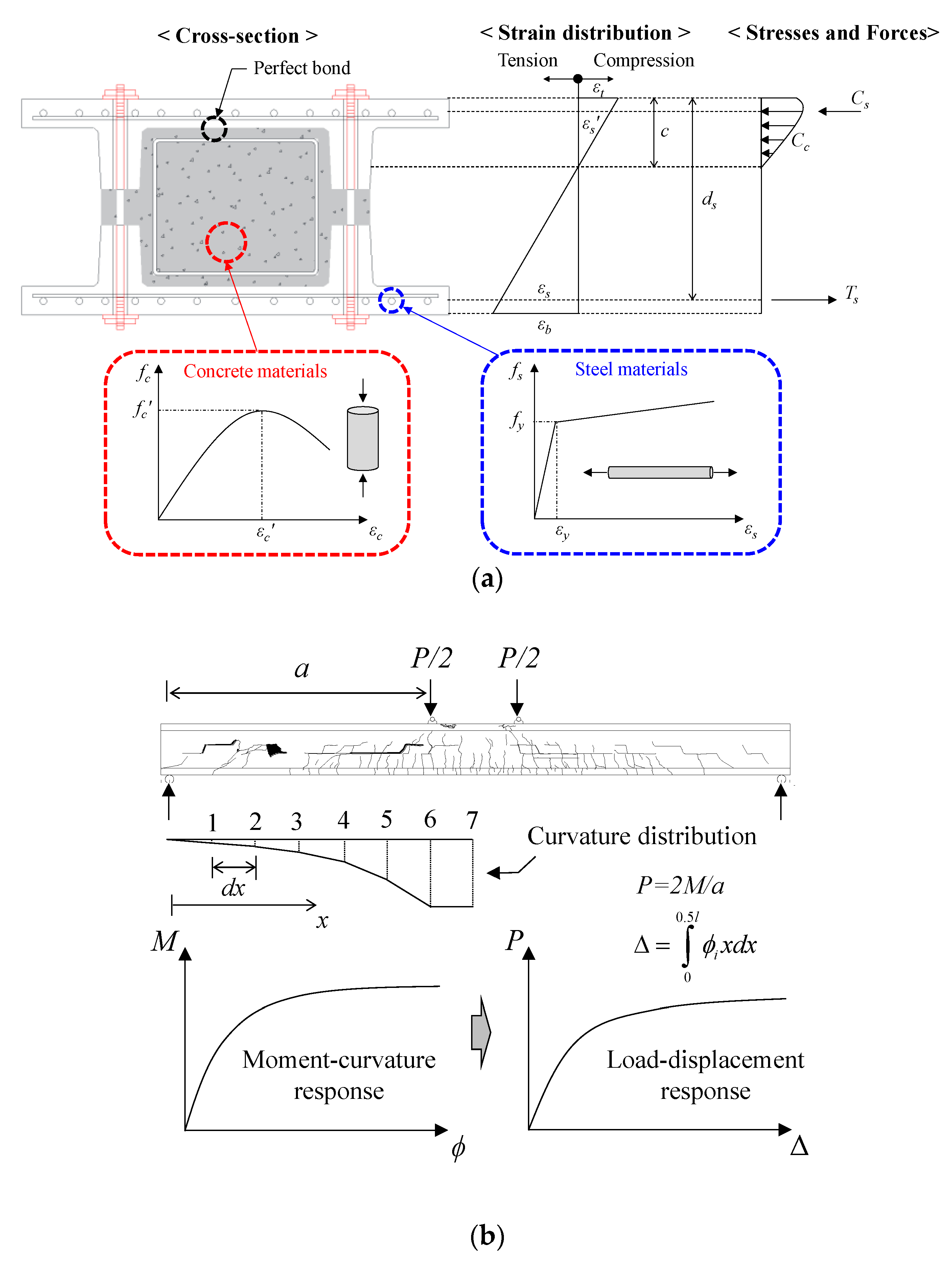
3.1. Non-Linear Flexural Analysis Model

Figure 9 shows a non-linear flexural analysis model for evaluating the flexural behavior of the DCW member. Since no damage was observed at the interface between the PC panel and CIP concrete in the DCW-SN specimen, the interface layers of the PC panel and CIP concrete were assumed to be fully bonded in the flexural analysis for this member. Under the assumption of the concrete strain at the extreme compression fiber ( ε t ) and the neutral axis depth ( c ), the strain in concrete ( ε c , i ) at an arbitrary distance ( d i ) away from the extreme compression fiber, the strain of tensile reinforcement ( ε s ), and the strain of compressive reinforcement ( ε s ) can be calculated as follows:
ε c , i = ε t ε t c d i ,
ε s = ε t ε t c d s ,
ε s = ε t ε t c d s .
where d s and d s are the depths of the tensile and compressive reinforcements, respectively. The stresses corresponding to each strain can be calculated by substituting the strain of each element derived from Equations (4) to (6) into the constitutive laws of the materials. In this study, the Popovics model [17] was applied to concrete, while the elasto-linear hardening model [18] was applied to steel reinforcement, as shown in Figure 9a.
f c = f c   2 ε c ε c ε c ε c 2   ( when   ε c 0 ) ,
f s = ε s E s   ( when   ε s ε y ) ,
f s = f y + ε s ε y E s p   ( when   ε s > ε y ) ,
where f c   is the compressive strength of concrete; ε c   is the compressive strain of concrete corresponding to f c   ; E s is the elastic modulus of steel reinforcement (190 GPa is used based on the material test); f y and ε y are the yield strength and strain of steel reinforcement, respectively; and E s p is the elastic modulus of the steel reinforcement after yielding, which is taken to be 0.01 E s .
When the concrete stress ( f c , i ) of each layer is calculated using Equations (4) and (7), the compressive force of concrete ( C c ) can be calculated by accumulating the stress of each layer, as follows:
C c = ε c , i 0 f c , i b i z i ,
where b i and z i are the width and height of each concrete layer, respectively. The force of tensile reinforcement ( T s ) and the force of compressive reinforcement ( T s ) can be calculated by multiplying the stress estimated using Equations (8) and (9) by the sectional area of the steel reinforcement, and C c , T s , and T s should meet the following force equilibrium condition:
F = C c + T s + T s = 0 .
when the force equilibrium condition is met, the bending moment ( M ) and curvature ( ϕ ) acting on the section can be calculated as follows:
M = d i c f c , i b i z i d i + T s d s + T s d s ,
ϕ = ε t c
Based on the moment–curvature response of the section obtained from the above process, the load-displacement behavior of the member can be derived, as shown in Figure 9b, where the center deflection of the member ( Δ ) can be calculated as follows [17]:
Δ = 0 0.5 l ϕ x d x ,
where l is the span length, and x is the distance from the support to an arbitrary location. In the analysis of the DCW-F specimen, it was assumed that when the strain of concrete at the extreme compression fiber ( ε t ) reached −0.0035, the member suffered flexural failure [19,20].

3.2. Finite Element Model

The shear test results showed that although the bolts used in the assembly of PC panels contributed to the improvement in the shear performance of the DCW, they failed to exhibit the yield strain until the maximum load was reached. It is estimated that this occurred because the bolt was not fully embedded in the PC panel concrete, but instead was composite with the PC panel by the grout injected into the bolt hole during the assembly process, as shown in Figure 4e. Thus, the bolt and the PC panel failed to achieve a fully composite behavior. Therefore, in this study, a finite element analysis using ABAQUS/Standard [21], a general-purpose analysis software, was performed to investigate the shear behavior of the DCW specimens according to the bond properties of the bolts and PC panels.
Figure 10 shows the finite element analysis model for the DCW specimens. PC panels, CIP concrete, and bolts were modeled as solid elements; reinforcing bars were modeled as truss elements; and the PC panel and reinforcing bar were modeled to achieve a perfect bond. In addition, since the end slip that occurred between the PC panel and the CIP concrete in the experiment was negligibly small, the PC panel and CIP concrete were modeled to be fully composite, and the material models corresponding to each element were applied in the same manner as that presented in the non-linear flexural analysis model. The loading and support plates were also modeled to realistically simulate the experimental conditions as they were, and displacement control method was used to apply the loads to the specimens.
For the DCW-SB specimen, to consider the bond behavior of the PC panel and bolts in the shear analysis, the constitutive laws specified in the fib model code 2010 [22] were applied to the bond–slip relationship between PC panel and bolt elements, as shown in Figure 10b, and assuming “all other bond condition”, the maximum bond stress ( τ max ) was calculated as 1.25 f c m , where f c m is the mean compressive strength. Note that the bond–slip relationship was modified and applied to ABAQUS in a bi-linear form, as shown in the lower part of Figure 10b. In addition, the concrete damaged plasticity (CDP) model [23] was used as the yield criterion of concrete, and an angle of 37° [24] was applied as the dilation angle based on the existing literature.

4. Analysis Results and Discussions

4.1. Comparison of Test and Analysis Results

Figure 11 compares the test and analysis results of the DCW-F specimen. It appears that the proposed non-linear flexural analysis model was able to estimate the initial stiffness and post-cracking stiffness of the specimen very closely and predict the flexural strength of the specimen and the displacement at failure with a high level of accuracy. Therefore, it is ascertained that the non-linear flexural analysis model proposed in this study can be applied in the design of DCW and prediction of its flexural behavior.
Figure 12 compares the test and analysis results of the DCW-SN and DCW-SB specimens. The finite element model adequately evaluated the shear behavior of the DCW-SN specimen without bolts and provided very approximate estimations not only on the shear strength of the specimen, but also on the displacement at failure. In particular, it was found that for the DCW-SB specimen with bolts placed in the shear span, the member behavior under high loads is greatly affected by the bond performance between the PC panel and bolt elements, as shown in Figure 12b. When a perfect bond was assumed between the PC panel and bolt, the finite element model was found to overestimate the shear strength of the specimen. On the contrary, when the bond between the PC panel and bolt was not considered in the shear analysis (i.e., non-composite condition), the finite element model provided conservative shear strength estimation results. The analysis model to which the constitutive laws for the bond–slip relationship were applied, considering the partial interaction between the PC panel and bolt, estimated the shear behavior of the specimen most closely. In particular, it showed relatively good simulations not only of the shear strength of the specimen, but also of the behavior of the bolt according to the load, as shown in Figure 12c. From the experiment and analysis results, it appears that the bolt exerted approximately 65–70% of its yield strength ( f y b ) at the shear failure of the specimen, based on which the following section aims to propose a practical shear strength equation for DCW members with CIP concrete and bolts.

4.2. Practical Shear Strength Equation

Previously, the shear behavior of DCW was analyzed in detail through the finite element analysis shown in Figure 10 and Figure 12. However, in practice a straightforward calculation method is required for the shear design of the DCW. In this regard, this study proposed a method to estimate the shear strength of a DCW section composed of PC panels, CIP concrete, and bolts based on the ACI 318-19 and KCI 2017 codes [15,25].
The ACI 318-19 and KCI 2017 codes specify that the shear strength of concrete ( V c ) and the contribution of shear reinforcement ( V s ) in RC members with stirrups should be calculated, respectively, as follows:
V c = 1 6 f c b w d s ,
V s = A v f v y d s s v ,
where f c is the compressive strength of concrete; b w is the web width; d s is the effective depth of tensile reinforcement; A v and f v y are the sectional area and yield strength of shear reinforcement, respectively; and s v is the spacing of transverse reinforcing bars. As shown in the upper part of Figure 13, if the compressive strengths of the PC panel ( f c , P C ) and CIP concrete ( f c , C I P ) are applied to the red and blue areas, respectively, and the stress of the bolt at shear failure is assumed to be 65% of its yield strength ( f y b ) based on the test and analysis results, the shear strength of the DCW section can be represented by the following equation:
V n = V c , P C + V c , C I P + 0.65 V b o l t = 1 6 f c , P C b w d s + f c , C I P b C I P d s + 0.65 A b v f y b d s s b v ,
where b w and b C I P are the web widths of the PC panel and CIP concrete, respectively. The lower part of Figure 13 shows that Equation (17) can reflect the shear contribution of the bolt very reasonably, considering the partial interaction between the PC panel and the bolt. Meanwhile, it should be noted that for the shear contribution of concrete ( V c ), the proposed equation underestimated the test result because the ACI 318-19 and KCI 2017 code equations were derived to obtain the shear strength estimation results on the safe side [18]. This could be deemed a safety margin in practical design. Consequently, in Equation (17), the shear contributions of the concrete and steel elements constituting the DCW section were reasonably considered, and the shear strength of the DCW-SB(1) specimen with bolts was evaluated conservatively. Therefore, it is expected that economical and reasonable design results can be obtained using Equation (17) when estimating the shear strength of the DCW section.

5. Conclusions

In this paper, experimental and analytical studies were conducted on a double composite wall (DCW) that is suitable for large-scale basement wall construction. The failure patterns, flexural and shear responses, and slip between the PC panel and the CIP concrete of the specimens were measured and analyzed in detail. A non-linear flexural analysis was performed on the flexural specimen, and a finite element analysis was carried out on the shear specimens to quantitatively evaluate the flexural and shear performances of the DCW. In addition, a straightforward calculation method for the practical shear design of DCW was proposed based on the current design codes. On this basis, the following conclusions can be drawn:
  • The end slip between the PC panel and CIP concrete in the flexural and shear specimens was only 0.02 and 0.03 mm, respectively, and the composite performance of the PC panel and CIP concrete was found to be excellent. This is because rough surface finishing was applied to the PC panel, and the shear keys of the upper and lower panels were interlocked with each other.
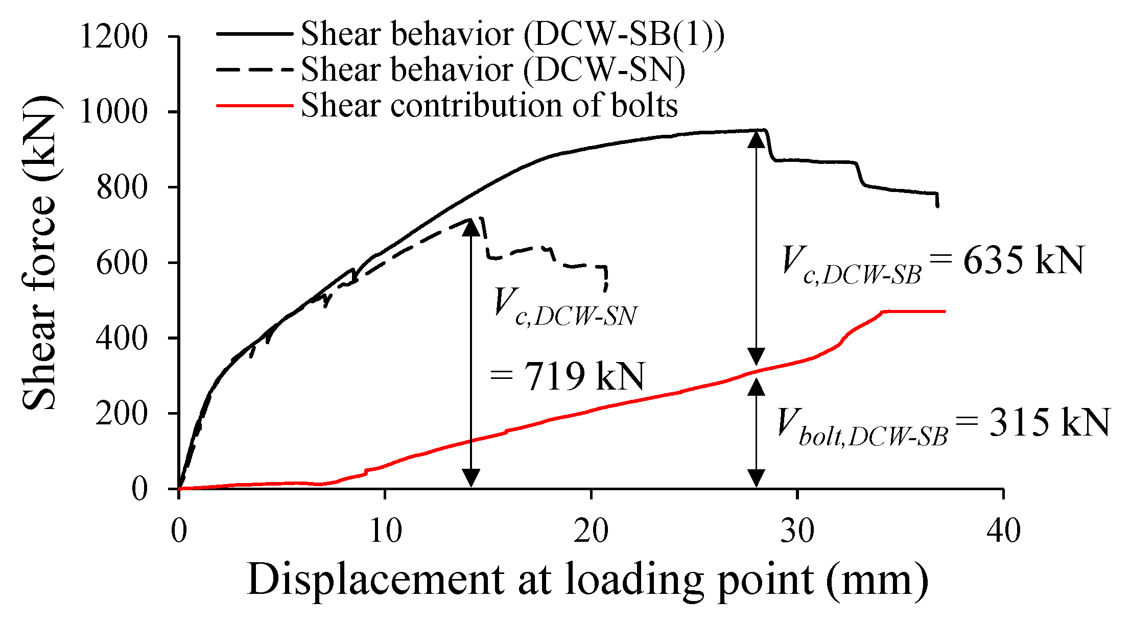
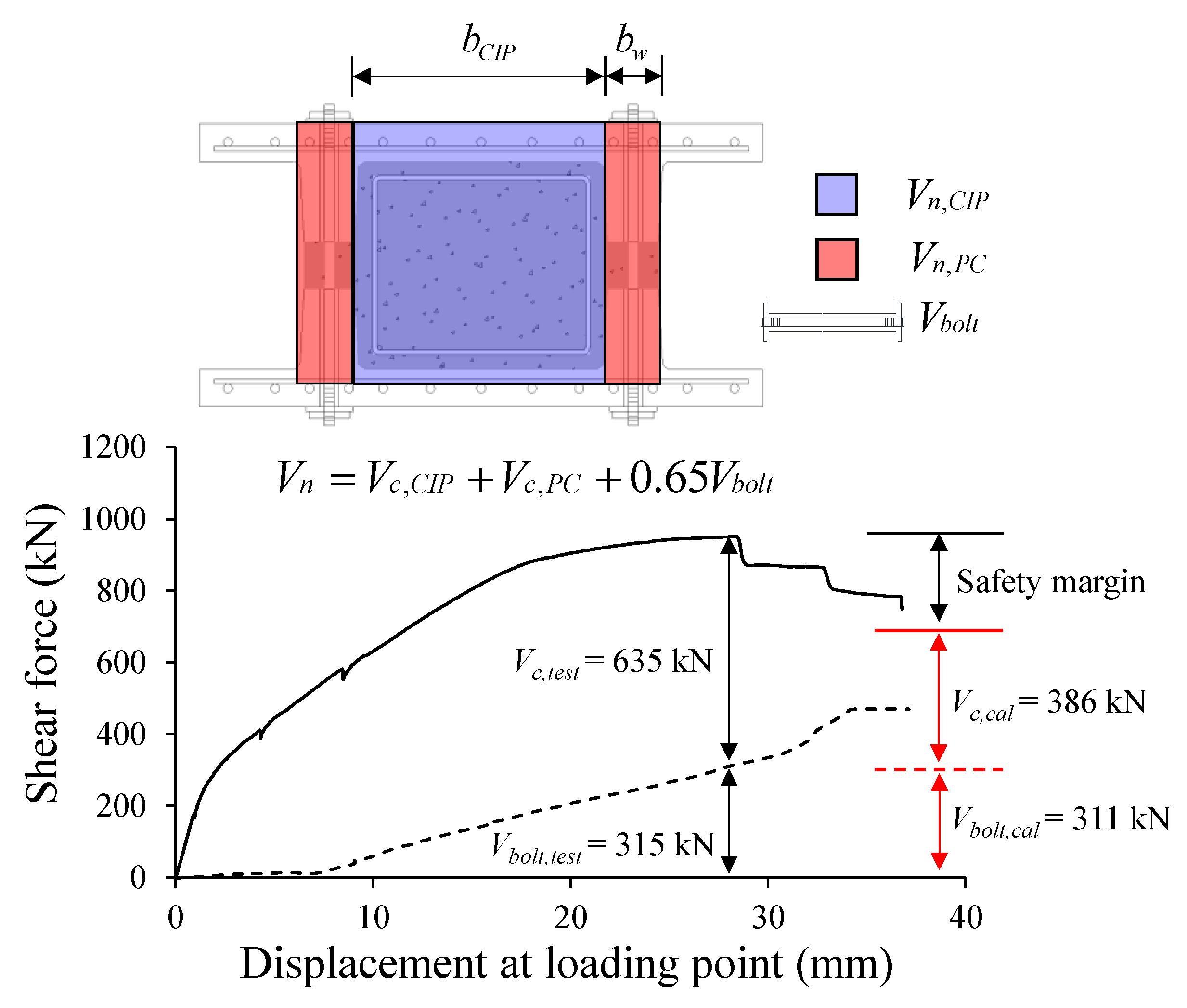
  • In the composite DCW, although the bolts used for assembling the PC panels contributed considerably to the shear resistance mechanism of the member after inclined shear cracking, they failed to exhibit the yield strain until the maximum load was reached. This is because the bolt was not fully embedded in the PC panel concrete, but instead was composite with the PC panel by grout injected into the bolt hole during the assembly process; thus, the bolt and the PC panel failed to achieve fully composite behavior.
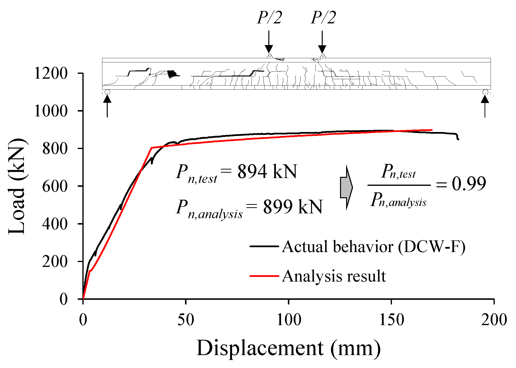
  • The non-linear flexural analysis model provided very good estimations not only of the flexural strength of the DCW member but also of its initial stiffness and post-cracking stiffness. Therefore, the non-linear flexural analysis model proposed in this study can be adequately applied in the design of DCW and the prediction of its flexural behavior.
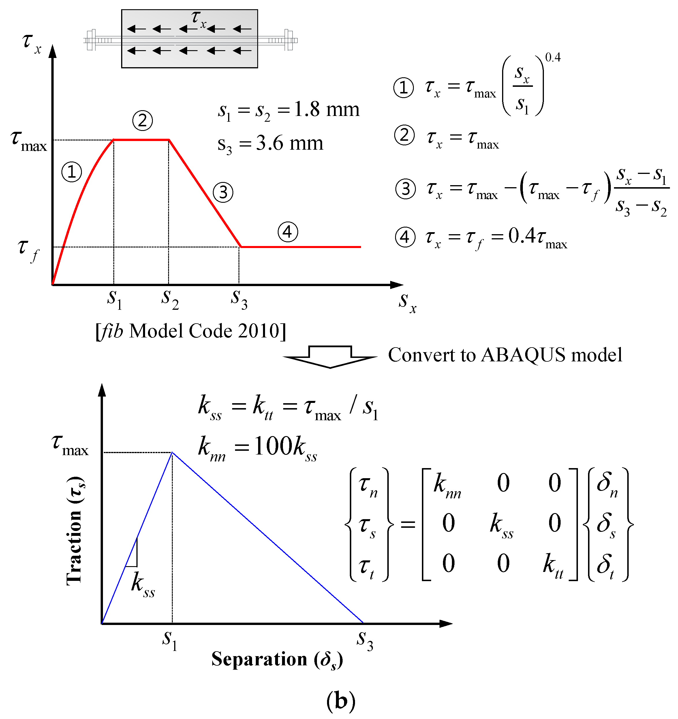
  • The finite element analysis results showed that when the bolt and the PC panel were assumed to be fully composite, the finite element model overestimated the shear strength of the specimen. However, when the constitutive laws for the bond–slip relationship suggested in the fib model code 2010 were taken into account, the analysis model evaluated the shear behavior of the specimen well, including the shear contribution of the bolts according to the load. In addition, the proposed practical equation, which considers the shear contributions of all the elements constituting the DCW section, provided reasonable shear strength estimation results on the safe side in a simple manner.
  • The flexural and shear performances of the DCW member were investigated in this study. For the DCW to be practically applied to construction sites, however, additional experimental and analytical research needs to be conducted regarding the flexural behavior at the foundation–DCW connection.

Author Contributions

Original draft manuscript, S.-J.H.; validation, I.H.; investigation, J.-H.K., Y.-H.O; supervision and review writing, K.-S.K. All authors have read and agreed to the published version of the manuscript.

Funding

This research was supported by the Basic Science Research Program through the National Research Foundation of Korea (NRF), funded by the Ministry of Education (NRF-2020R1I1A3054759).

Institutional Review Board Statement

Not applicable.

Informed Consent Statement

Not applicable.

Data Availability Statement

The data presented in this study are available on request from the corresponding author.

Conflicts of Interest

The authors declare no conflict of interest.

References

  1. Han, S.J.; Jeong, J.H.; Joo, H.E.; Choi, S.H.; Choi, S.; Kim, K.S. Flexural and Shear Performance of Prestressed Composite Slabs with Inverted Multi-Ribs. Appl. Sci. 2019, 9, 4946. [Google Scholar] [CrossRef] [Green Version]
  2. Ju, H.; Han, S.J.; Joo, H.E.; Cho, H.C.; Kim, K.S.; Oh, Y.H. Shear Performance of Optimized-Section Precast Slab with Tapered Cross Section. Sustainability 2018, 11, 163. [Google Scholar] [CrossRef] [Green Version]
  3. Hou, H.; Liu, X.; Qu, B.; Ma, T.; Liu, H.; Feng, M.; Zhang, B. Experimental evaluation of flexural behavior of composite beams with cast-in-place concrete slabs on precast prestressed concrete decks. Eng. Struct. 2015, 126, 405–416. [Google Scholar] [CrossRef]
  4. University of Seoul. Development of Double Composite Wall System Suitable for Basement Exterior Wall Construction; Research Report; University of Seoul: Seoul, Korea, 2018. [Google Scholar]
  5. Moon, J.H.; Choi, H.C. MDW Structural Performance Test Report; Hannam University: Daejeon, Korea, 2016. [Google Scholar]
  6. Ji, K.H.; Choi, B.J. Improvement of Underground Wall Design and Construction Safety Using Mega Double Wall Construction Method. J. Korean Soc. Hazard Mitig. 2019, 19, 1–12. [Google Scholar] [CrossRef]
  7. Kim, S.; Lee, D.E.; Kim, Y.; Kim, S. Development and Application of Precast Concrete Double Wall System to Improve Productivity of Retaining Wall Construction. Sustainability 2020, 12, 3454. [Google Scholar] [CrossRef] [Green Version]
  8. McKinley, B.; Boswell, L.F. Behaviour of double skin composite construction. J. Constr. Steel. Res. 2002, 58, 1347–1359. [Google Scholar] [CrossRef]
  9. Ji, X.; Cheng, X.; Jia, X.; Varma, A.H. Cyclic In-Plane Shear Behavior of Double-Skin Composite Walls in High-Rise Buildings. J. Struct. Eng. 2017, 143, 04017025. [Google Scholar] [CrossRef]
  10. Qin, Y.; Shu, G.P.; Zhou, G.G.; Han, J.H. Compressive behavior of double skin composite wall with different plate thicknesses. J. Constr. Steel. Res. 2019, 157, 297–313. [Google Scholar] [CrossRef]
  11. Holden, T.; Restrepo, J.; Mander, J.B. Seismic Performance of Precast Reinforced and Prestressed Concrete Walls. J. Struct. Eng. 2003, 129, 286–296. [Google Scholar] [CrossRef]
  12. Nie, J.G.; Hu, H.S.; Fan, J.S.; Tao, M.X.; Li, S.Y.; Liu, F.J. Experimental study on seismic behavior of high-strength concrete filled double-steel-plate composite walls. J. Constr. Steel. Res. 2013, 88, 206–219. [Google Scholar] [CrossRef]
  13. Yamamura, K.; Kiyomiya, O. Shear Capacity Enhancement of Existing Underground Wall Structures Using Postinstalled Reinforcing Bars. J. Struct. Eng. 2014, 140, 04013066. [Google Scholar] [CrossRef]
  14. Hilo, S.J.; Badaruzzaman, W.H.W.; Osman, S.A.; Al-Zand, A.W. Structural behavior of composite wall systems strengthened with embedded cold-formed steel tube. Thin-Walled Struct. 2016, 98, 607–616. [Google Scholar] [CrossRef]
  15. ACI Committee 318. Building Code Requirements for Structural Concrete (ACI 318-19); American Concrete Institute: Farmington Hills, MI, USA, 2019. [Google Scholar]
  16. Ju, H.; Han, S.J.; Choi, I.S.; Choi, S.; Park, M.K.; Kim, K.S. Experimental Study on an Optimized-Section Precast Slab with Structural Aesthetics. Appl. Sci. 2018, 8, 1234. [Google Scholar] [CrossRef] [Green Version]
  17. Collins, M.P.; Mitchell, D. Prestressed Concrete Structures; Prentice-Hall: Bergen County, NJ, USA, 1991. [Google Scholar]
  18. Lee, D.H.; Han, S.J.; Kim, K.S. Dual Potential Capacity Model for Reinforced Concrete Beams Subjected to Shear. Struct. Conc. 2016, 17, 443–456. [Google Scholar] [CrossRef]
  19. Ju, H. Multi-Potential Capacity Model for Torsion in Reinforced Concrete Members Subjected to Combined Loads. Ph.D. Thesis, University of Seoul, Seoul, Korea, 2017. [Google Scholar]
  20. MacGregor, J.G.; Wight, J.K. Reinforced Concrete Mechanics and Design, 4th ed.; Prentice-Hall: Bergen County, NJ, USA, 2006. [Google Scholar]
  21. ABAQUS. Standard User’s Manual, Ver.6.9; Hibbit, Karlsson & Sorensen Inc.: Providence, RI, USA, 2003. [Google Scholar]
  22. International Federation for Structural Concrete (fib). Model Code 2010; Final Version; fib Bulletins 65 & 66; International Federation for Structural Concrete: Lausanne, Switzerland, 2012. [Google Scholar]
  23. Genikomsou, A.S.; Polak, M.A. Finite element analysis of punching shear of concrete slabs using damaged plasticity model in ABAQUS. Eng. Struct. 2015, 98, 38–48. [Google Scholar] [CrossRef]
  24. Sümer, Y.; Aktaş, M. Defining parameters for concrete damage plasticity model. Chall. J. Struct. Mech. 2015, 1, 149–155. [Google Scholar] [CrossRef]
  25. KCI. Korea Model Code 2017; Korea Concrete Institute: Seoul, Korea, 2017. [Google Scholar]
Figure 1. Characteristics of the double composite wall (DCW) system.
Applsci 11 00506 g001
Figure 2. Construction process of a real-scale double composite wall (DCW) system: (a) assembling mold; (b) placing reinforcements; (c) casting precast concrete; (d) assembling precast panels; (e) installing precast panels; (f) casting in-filled concrete; (g) after construction.
Applsci 11 00506 g002
Figure 3. Section details of test specimens (unit: mm): (a) specimen naming; (b) DCW-F specimen; (c) DCW-SN specimen; (d) DCW-SB (1) and (2) specimens.
Applsci 11 00506 g003aApplsci 11 00506 g003b
Figure 4. Fabrication process of DCW specimens: (a) formwork; (b) casting precast concrete; (c) steam curing; (d) assembling panels using bolts; (e) grouting; (f) pouring cast-in-place (CIP) concrete.
Applsci 11 00506 g004
Figure 5. Loading details (unit: mm): (a) DCW-F specimen; (b) DCW-S specimen series.
Applsci 11 00506 g005
Figure 6. Flexural behavior of DCW-N specimen: (a) load–displacement behavior; (b) longitudinal strain distribution in the section at the mid-span (see Figure 5a for gauge locations); (c) measured end slip between the PC panel and the CIP concrete.
Applsci 11 00506 g006
Figure 7. Shear behavior of the DCW-S specimen series: (a) DCW-SN specimen; (b) DCW-SB(1) specimen; (c) DCW-SB(2) specimen; (d) measured end slip (DCW-SN specimen); (e) measured bolt strains (DCW-SB(1) specimen).
Applsci 11 00506 g007aApplsci 11 00506 g007b
Figure 8. Shear contribution of each element.
Applsci 11 00506 g008
Figure 9. Nonlinear flexural analysis model: (a) schematic description of flexural analysis; (b) numerical integration for obtaining displacement.
Applsci 11 00506 g009
Figure 10. Finite element model for shear analysis: (a) schematic description of the finite element model; (b) bond–slip relationship between bolts and concrete.
Applsci 11 00506 g010aApplsci 11 00506 g010b
Figure 11. Comparison of the test and analysis results (DCW-F specimen).
Applsci 11 00506 g011
Figure 12. Comparison of the test and analysis results (DCW-S specimens): (a) DCW-SN specimen; (b) DCW-SB(1) specimen; (c) comparison of the bolt contributions in DCW.
Applsci 11 00506 g012aApplsci 11 00506 g012b
Figure 13. Shear strength estimation methods for DCW.
Applsci 11 00506 g013
Table 1. Dimensions and material properties of the test specimens.
SpecimenhtfdsbbwAsAsvAbvfyfvyfvbf’c,PCf’c,CIP
mmmmmmmmmmmm2mm2mm2MPaMPaMPaMPaMPa
DCW-F1600805601190120372414362862559147642.623.5
DCW-SN6008056011901203724--62559147640.223.5
DCW-
SB(1)
6008056011901203724-62862559147640.423.5
DCW
-SB(2)
6008056011901203724-62862559147640.423.5
Notations: h: height of section; tf: thickness of precast concrete (PC) flange; ds: depth of tensile reinforcing bars; b: width of section; bw: width of PC web; As: amount of tensile reinforcing bars; Asv: amount of shear reinforcing bars; Abv: sectional area of bolt; fy: yield strength of tensile reinforcement; fvy: yield strength of shear reinforcement; fyb: yield strength of bolt; f’c,PC: compressive strength of precast concrete; f’c,CIP: compressive strength of cast-in-place (CIP) concrete.
Publisher’s Note: MDPI stays neutral with regard to jurisdictional claims in published maps and institutional affiliations.

