
Finite Element Analysis of Proposed Self-Locking Joint for Modular Steel Structures


Abstract
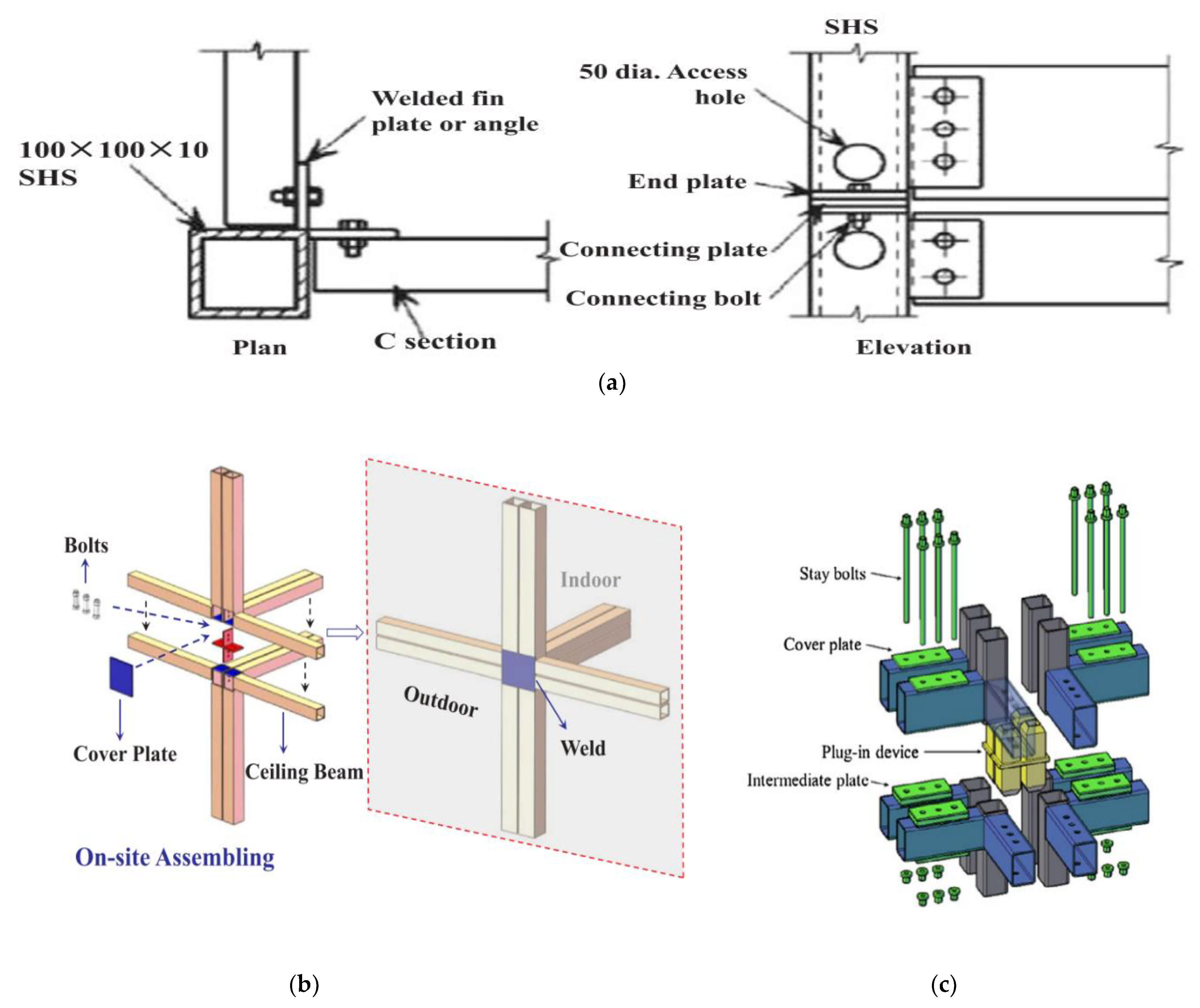
:1. Introduction
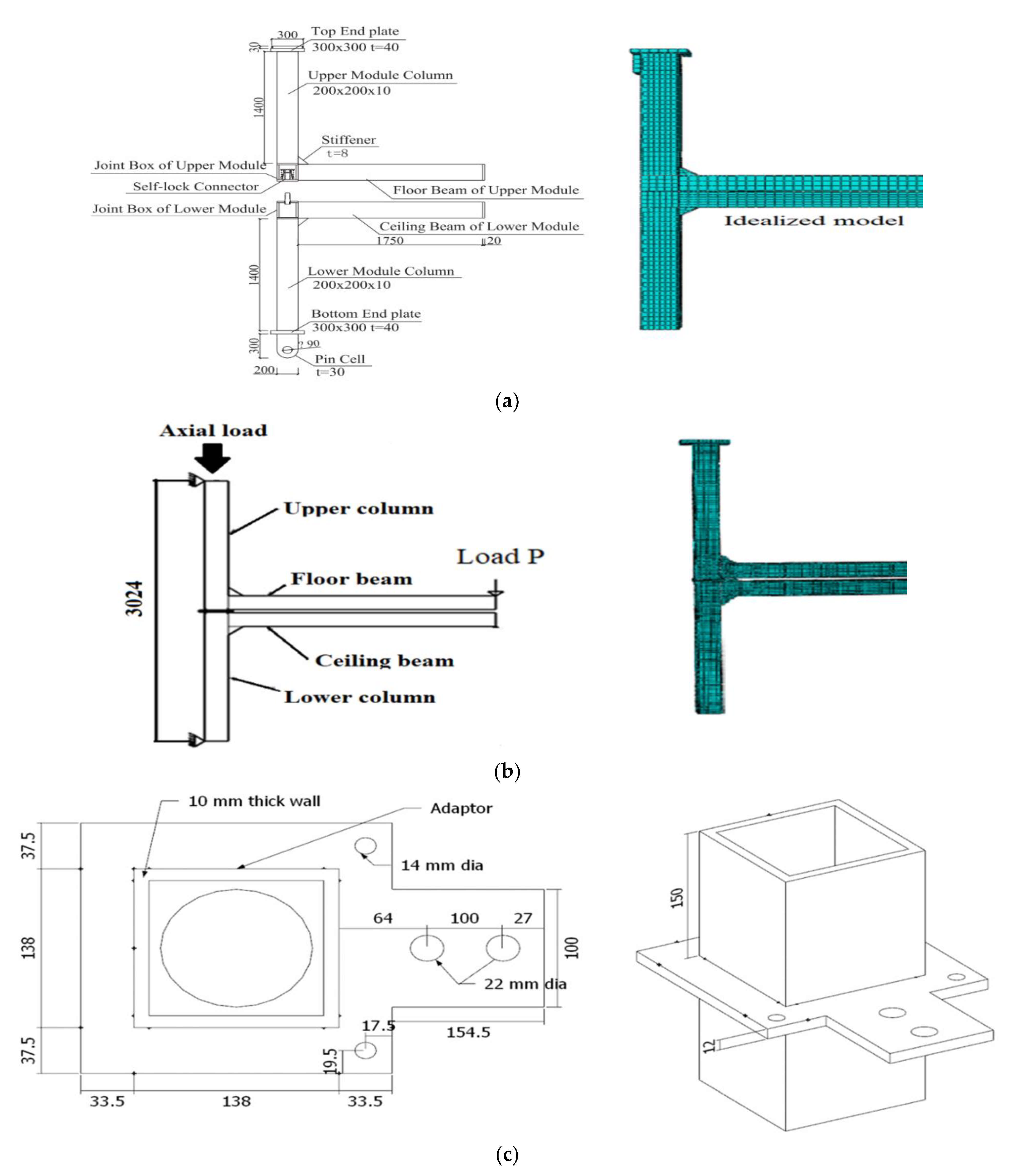
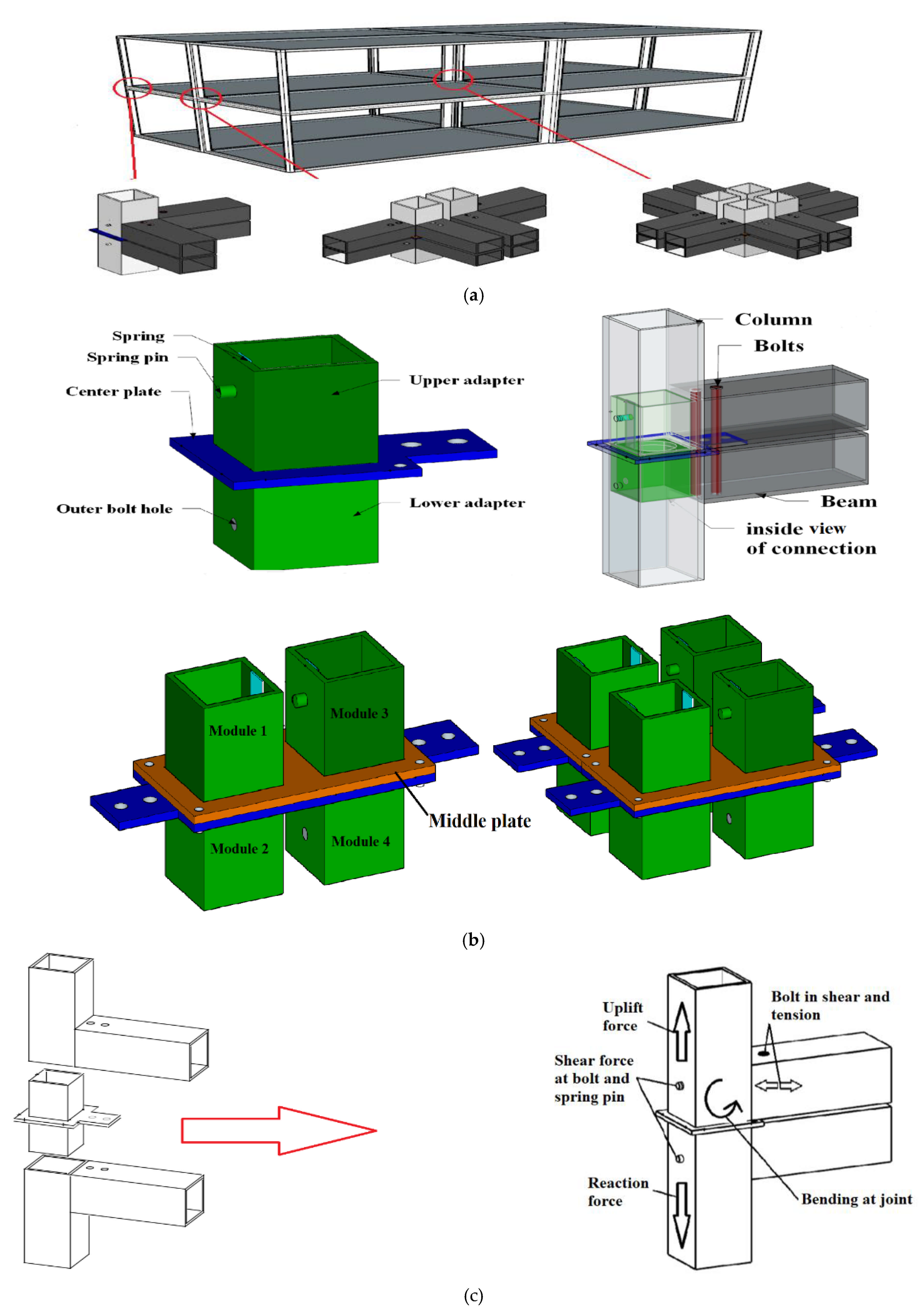
2. Working Mechanism of Proposed Intermodular Connection
3. Finite Element (FE) Model
3.1. Elements Type and Meshing
3.2. Interaction
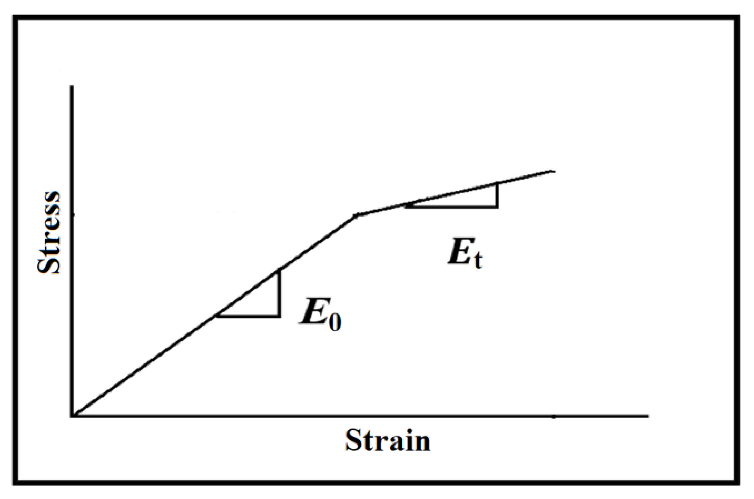
3.3. Material Modeling
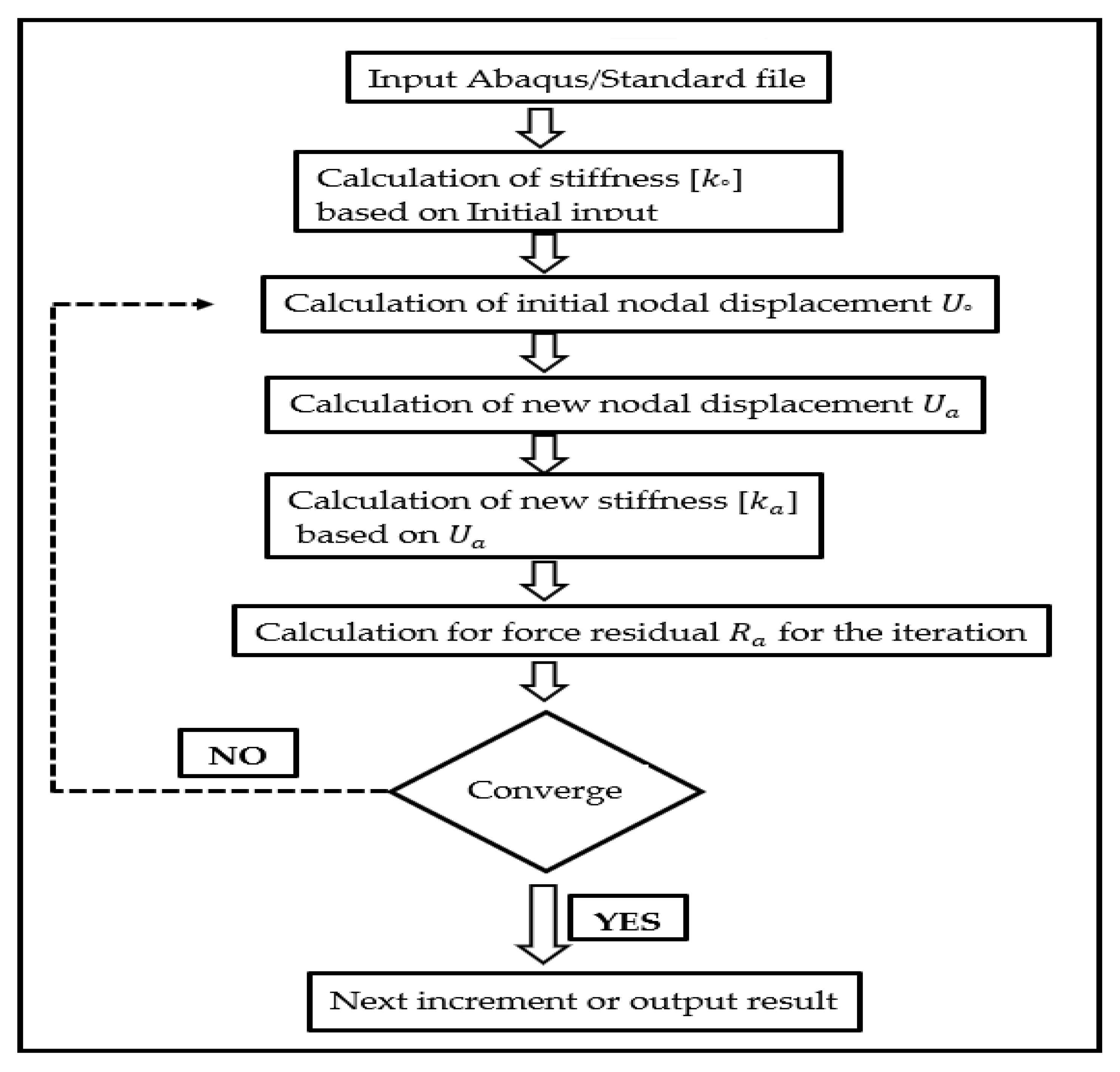
3.4. Analysis and Step Procedures
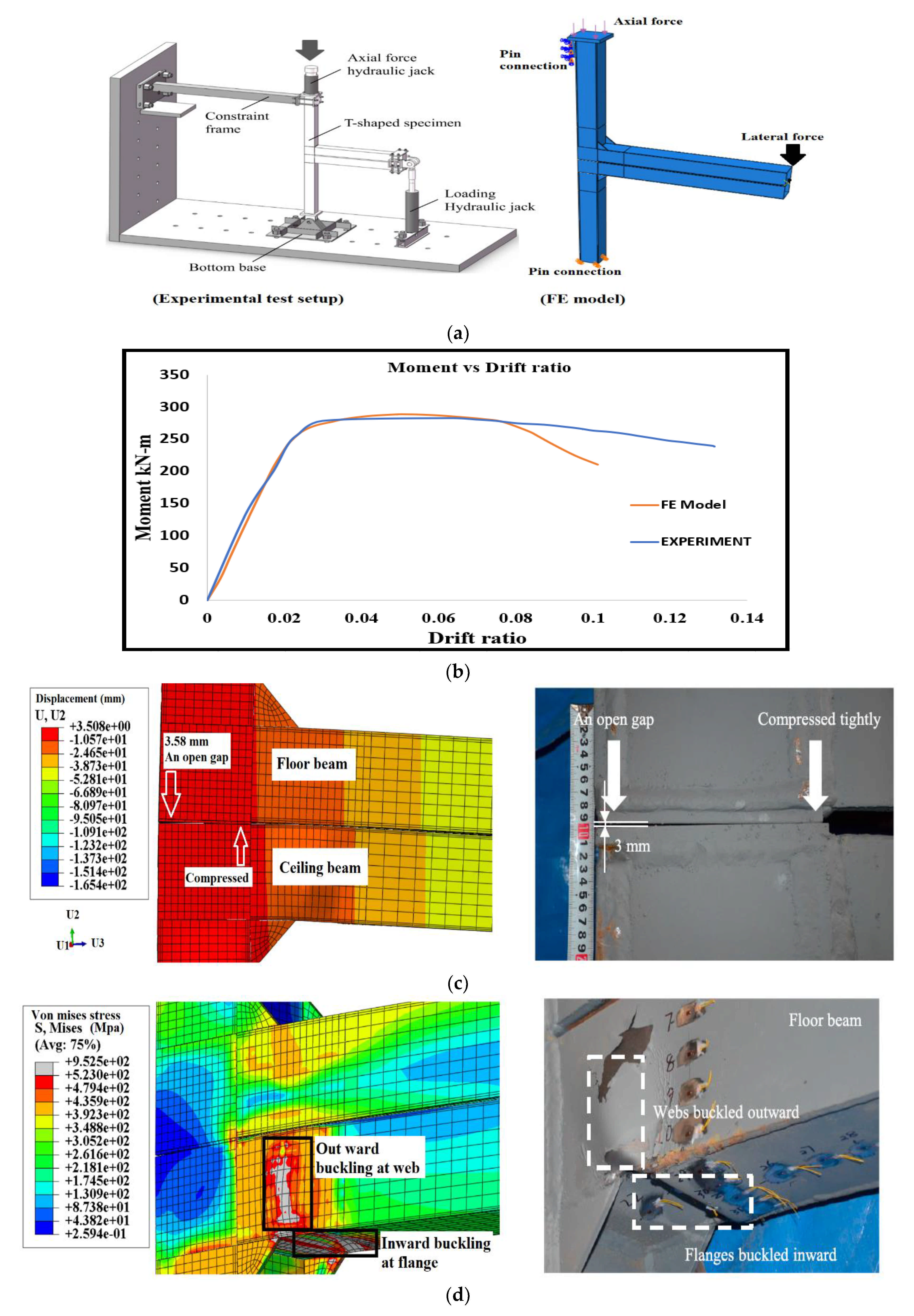
4. Validation of FE Model
5. Parametric Study on the Proposed Connection
5.1. Behavior of Proposed Connection (Cp1) under Static Lateral Loading
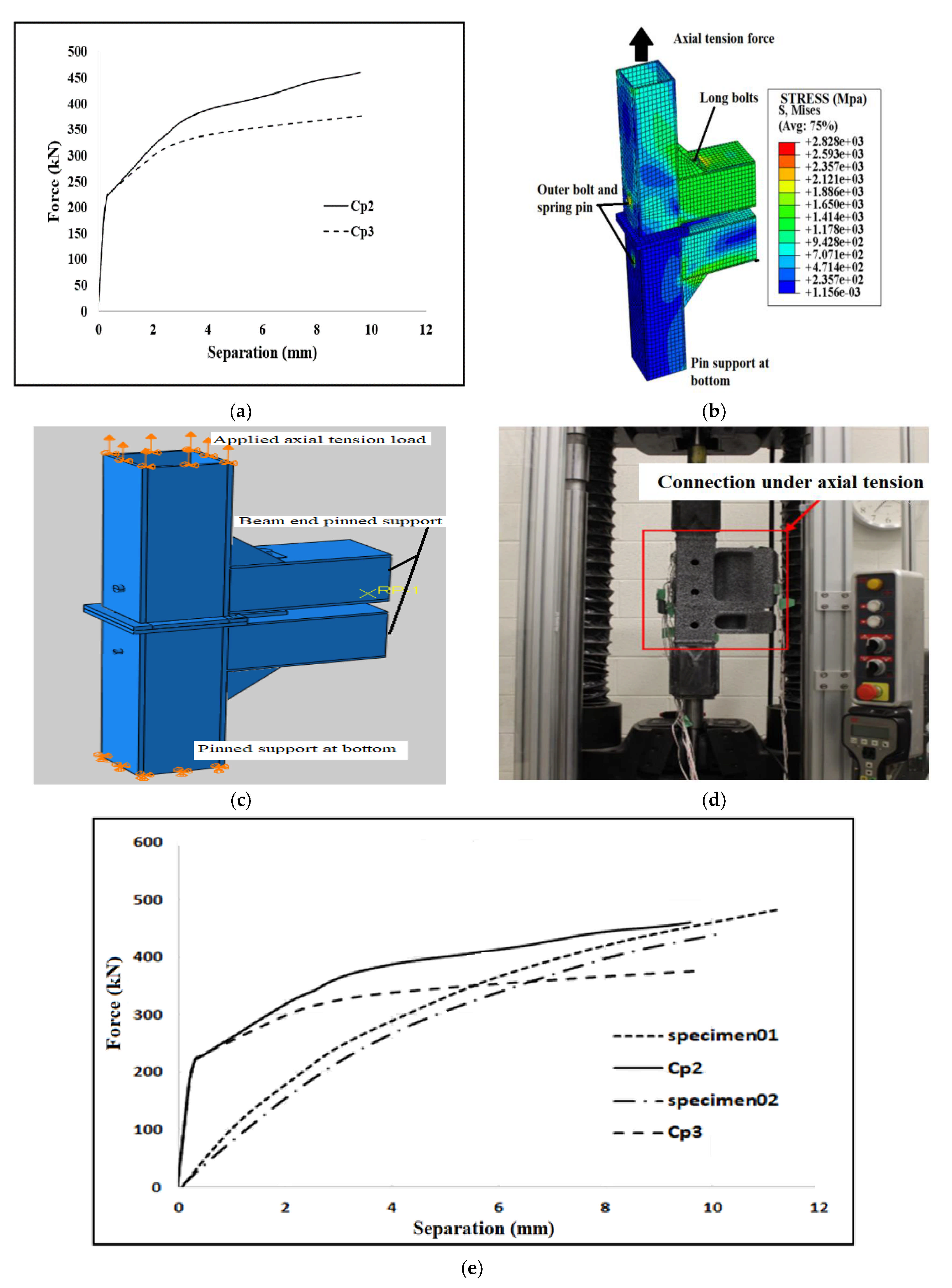
5.2. Connection under Axial Tension
Comparison with an Existing Connection
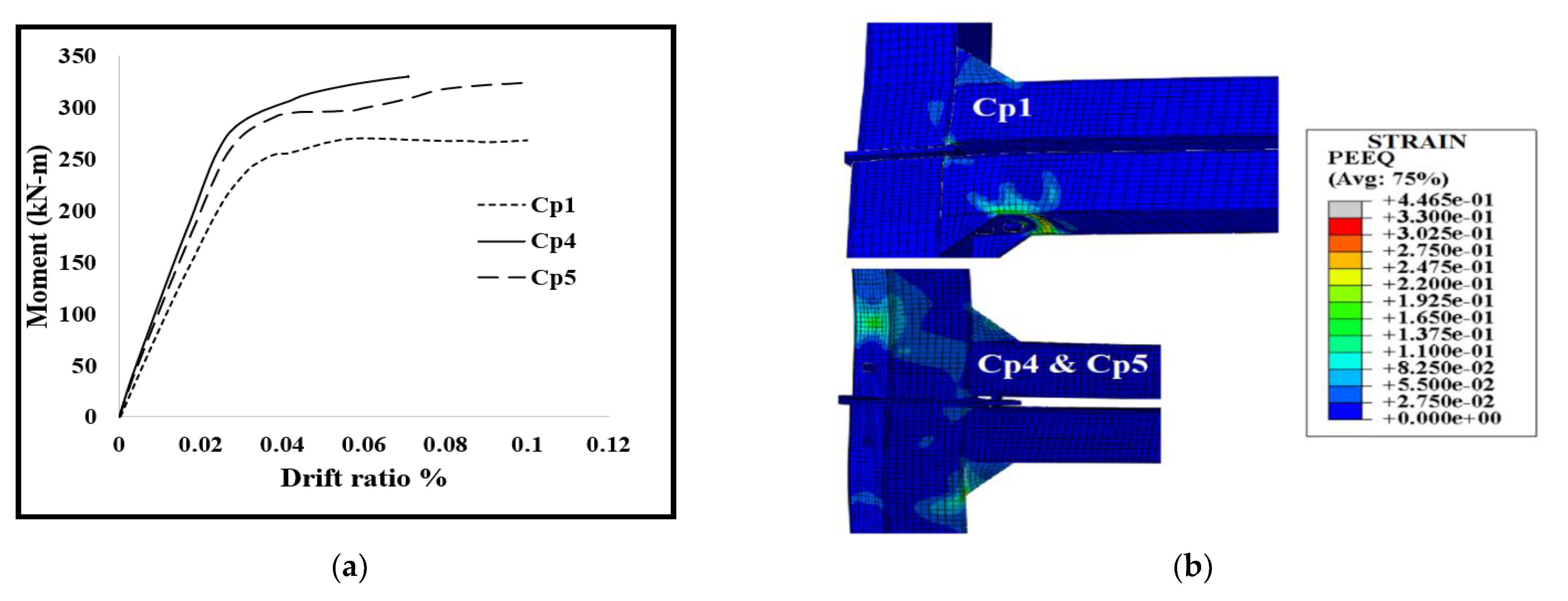
5.3. Effect of Beams Thickness
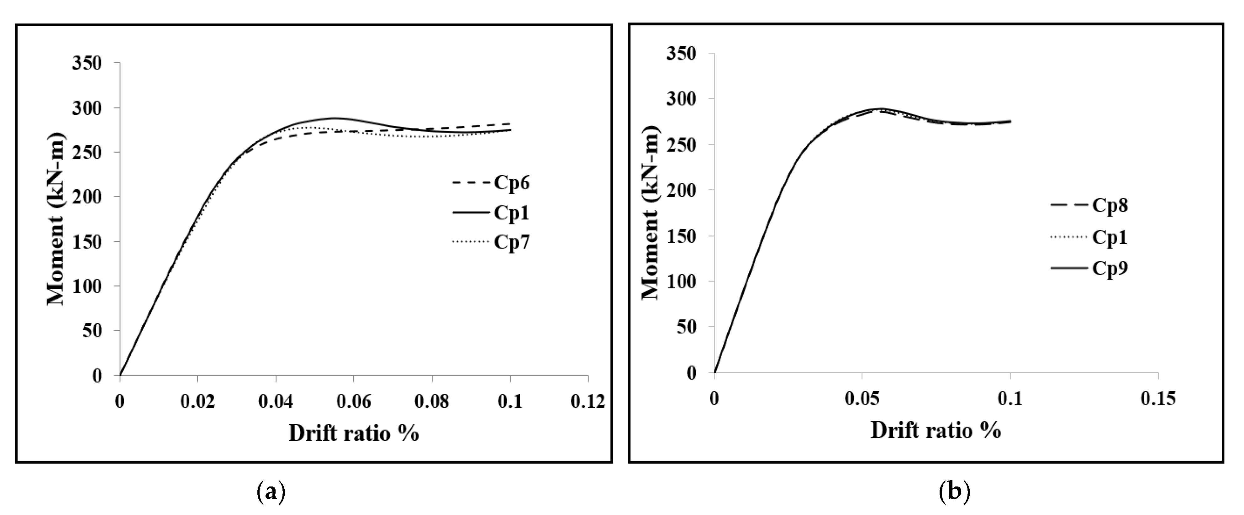
5.4. Effect of Bolt Pretension
5.5. Effect of Coefficient of Friction,
5.6. Ductility and Deformation Capacity
6. Conclusions
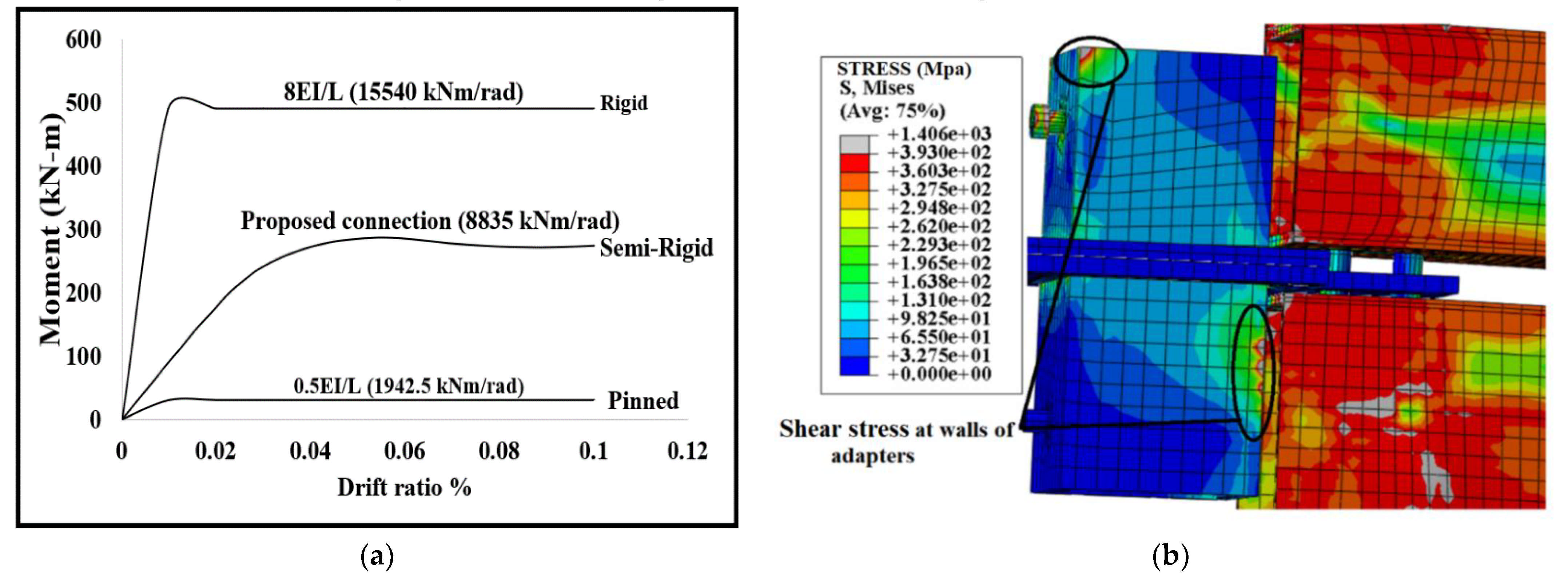
- The proposed connection was able to maintain 80% of Mu at a drift ratio of 0.04 radian, hence meeting the criteria of ductility; therefore, it can be categorized as special moment frame (SMF) according to AISC. The initial stiffness ratio was leftover between the boundaries of the rigid connection and pinned connection; for that reason, the proposed connection can be characterized as a semi-rigid connection according to Eurocode 3.
- The spring pin and outer bolt significantly mitigated the separation between column and connection under axial tension load. The proposed connection contributed sufficiently to carrying the bending moment produced at the joint; the upper and lower adapter has taken a load from the respective column by bearing action, which causes shear stress on the walls of the adapter.
- Load carrying capacity and initial rotational stiffness of joint increased with an increase in thickness of floor and ceiling beams. Bolt pretension force was up to 20% of ultimate strength of the bolt shown, increasing moment carrying capacity of the joint, further increasing the pretension force, and resulting in a decreased moment capacity of the joint.
Author Contributions
Funding
Institutional Review Board Statement
Informed Consent Statement
Data Availability Statement
Acknowledgments
Conflicts of Interest
References
- Navaratnam, S.; Ngo, T.; Gunawardena, T.; Henderson, D. Performance review of prefabricated building systems and future research in Australia. Buildings 2019, 9, 38. [Google Scholar] [CrossRef] [Green Version]
- Nadeem, G.; Safiee, N.A.; Bakar, N.A.; Karim, I.A.; Nasir, N.A.M. Connection design in modular steel construction: A review. Structures 2021, 33, 3239–3256. [Google Scholar] [CrossRef]
- Annan, C.D.; Youssef, M.A.; El Naggar, M.H. Assessment of overstrength and ductility of a four-story modular steel building braced frame. In Proceedings of the 2nd Canadian Conference on Effective Design of Structures McMaster University, Hamilton, ON, Canada, 20–23 May 2008. [Google Scholar]
- Styles, A.J.; Luo, F.J.; Bai, Y.; Murray-Parkes, J.B. Effects of joint rotational stiffness on structural responses of multi-story modular buildings. In Proceedings of the International Conference on Smart Infrastructure and Construction; ICE Publishing: London, UK, 2016; pp. 457–462. [Google Scholar]
- Wang, X.; Yuan, X.; Zeng, H.; Li, T.; Liang, Y.; Gao, X.; Yu, Y. Bearing Capacity and Failure Mode of a Light-Steel Tubular K-joint Connected by a Novel U-shape Connector. Appl. Sci. 2021, 11, 8587. [Google Scholar] [CrossRef]
- Cho, B.H.; Lee, J.S.; Kim, H.; Kim, D.J. Structural performance of a new blind-bolted frame modular beam-column connection under lateral loading. Appl. Sci. 2019, 9, 1929. [Google Scholar] [CrossRef] [Green Version]
- Wang, Y.; Xia, J.; Ma, R.; Xu, B.; Wang, T. Experimental study on the flexural behavior of an innovative modular steel building connection with installed bolts in the columns. Appl. Sci. 2019, 9, 3468. [Google Scholar] [CrossRef] [Green Version]
- Sun, Y.; Wang, J.; Wu, J.; Shi, W.; Ji, D.; Wang, X.; Zhao, X. Constraints hindering the development of high-rise modular buildings. Appl. Sci. 2020, 10, 7159. [Google Scholar] [CrossRef]
- Lacey, A.; Chen, W. Structural response of modular building subjected to earthquake loading. In Proceedings of the 13th International Conference on Steel, Space and Composite Structures, Western Australia, Perth, Australia, 31 January–2 February 2018. [Google Scholar]
- Sultana, P.; Youssef, M.A. Seismic performance of modular steel-braced frames utilizing superelastic shape memory alloy bolts in the vertical module connections. J. Earthq. Eng. 2020, 24, 628–652. [Google Scholar] [CrossRef]
- Paper, C.; Ontario, W.; Ontarioprofessor, W. Hysteretic characteristics of braced frames in modular steel buildings. In Proceedings of the Annual Conference—Canadian Society for Civil Engineering, London, UK, 1–4 June 2016; Volume 1. [Google Scholar]
- Lacey, A.W.; Chen, W.; Hao, H.; Bi, K. Structural response of modular buildings – An overview. J. Build. Eng. 2018, 16, 45–56. [Google Scholar] [CrossRef] [Green Version]
- Sultana, P.; Youssef, M.A. Seismic performance of modular steel frames equipped with shape memory alloy braces. Bull. Earthq. Eng. 2018, 16, 5503–5527. [Google Scholar] [CrossRef]
- Annan, C.D.; Youssef, M.A.; El Naggar, M.H. Seismic overstrength in braced drames of modular steel buildings. J. Earthq. Eng. 2009, 13, 1–21. [Google Scholar] [CrossRef]
- Lacey, A.; Chen, W.; Hao, H.; Bi, K. Numerical study of the structural response to wind loading: Modular building case study. In Proceedings of the 13th International Conference on Steel, Space and Composite Structures, Western Australia, Perth, Australia, 31 January–2 February 2018; pp. 1–10. [Google Scholar]
- Annan, C.D.; Youssef, M.; Naggar, M.H. Seismic performance of modular steel braced frames. In Proceedings of the 9th Canadian Conference on Earthquake Engineering, Ottawa, ON, Canada, 26–29 June 2007. [Google Scholar]
- Deng, E.-F.; Zong, L.; Ding, Y.; Luo, Y.-B. Seismic behavior and design of cruciform bolted module-to-module connection with various reinforcing details. Thin-Walled Struct. 2018, 133, 106–119. [Google Scholar] [CrossRef]
- Dai, X.M.; Zong, L.; Ding, Y.; Li, Z.X. Experimental study on seismic behavior of a novel plug-in self-lock joint for modular steel construction. Eng. Struct. 2019, 181, 143–164. [Google Scholar] [CrossRef]
- Chen, Z.; Liu, J.; Yu, Y.; Zhou, C.; Yan, R. Experimental study of an innovative modular steel building connection. J. Constr. Steel Res. 2017, 139, 69–82. [Google Scholar] [CrossRef]
- Hwan Doh, J.; Ho, N.M.; Miller, D.; Peters, T.; Carlson, D.; Lai, P. Steel Bracket Connection on Modular Buildings. J. Steel Struct. Constr. 2017, 2. [Google Scholar] [CrossRef] [Green Version]
- Lee, S.; Park, J.; Shon, S.; Kang, C. Seismic performance evaluation of the ceiling-bracket-type modular joint with various bracket parameters. J. Constr. Steel Res. 2018, 150, 298–325. [Google Scholar] [CrossRef]
- Chen, Z.; Liu, J.; Yu, Y. Experimental study on interior connections in modular steel buildings. Eng. Struct. 2017, 147, 625–638. [Google Scholar] [CrossRef]
- Sendanayake, S.V.; Thambiratnam, D.P.; Perera, N.; Chan, T.; Aghdamy, S. Seismic mitigation of steel modular building structures through innovative inter-modular connections. Heliyon 2019, 5, e02751. [Google Scholar] [CrossRef]
- Dhanapal, J.; Ghaednia, H.; Das, S.; Velocci, J. Structural performance of state-of-the-art VectorBloc modular connector under axial loads. Eng. Struct. 2019, 183, 496–509. [Google Scholar] [CrossRef]
- Lawson, M. Building Design using Modules; The Steel Construction Institute: Ascot, UK, 2007; pp. 1–16. [Google Scholar]
- Annan, C.D.; Youssef, M.A.; El-Naggar, M.H. Effect of directly welded stringer-to-beam connections on the analysis and design of modular steel building floors. Adv. Struct. Eng. 2009, 12, 373–383. [Google Scholar] [CrossRef]
- Khan, K.; Yan, J.B. Finite Element Analysis on Seismic Behaviour of Novel Joint in Prefabricated Modular Steel Building. Int. J. Steel Struct. 2020, 20, 752–765. [Google Scholar] [CrossRef]
- Simulia Abaqus/CAE 6.14 User’s Manual; Simulia: Johnston, RI, USA, 2014; pp. 1–1146.
- Rahiminia, F. Effects of Joint Panel Shear Deformation on Elasto-Plastic Behavior of Steel Beam-to-Column Connections; Kobe University: Kobe, Japan, 2013. [Google Scholar]
- Śledziewski, K.; Górecki, M. Finite element analysis of the stability of a sinusoidal web in steel and composite steel-concrete girders. Materials 2020, 13, 41. [Google Scholar] [CrossRef] [PubMed] [Green Version]
- Standards Australia, AS 4100–1998 (R2016) Steel structures; SAI Global Limited: Sydney, Australia, 1998.
- Design of Structural Connections to Eurocode 3; Bulding Research Establishment, Ltd.: Hertfordshire, UK, 2003; ISBN 8001028380.
- Taranath, B. Seismic Provisions for Structural Steel Buildings, ANSI/AISC 341-10. Struct. Anal. Des. Tall Build. 2011, 355–410. [Google Scholar] [CrossRef]
- Lee, J.; Goldsworthy, H.M.; Gad, E.F. Blind bolted moment connection to sides of hollow section columns. J. Constr. Steel Res. 2011, 67, 1900–1911. [Google Scholar] [CrossRef]
- Steel Tube Institute. Connecting Hollow Structural Section Members with Through-Bolts. Available online: https://steeltubeinstitute.org/resources/connecting-hollow-structural-section-members-bolts/2020 (accessed on 29 September 2021).
- Baniotopoulos, C.C.; Ivanyi, M. Semi-Rigid Joints in Structural Steelwork; Ivanyi, M., Baniotopoulos, C.C., Eds.; Springer: Vienna, Austria, 2000; ISBN 978-3-211-83331-5. [Google Scholar]


| Part | Section b × h (mm) | Thickness (mm) | Length (mm) | Plastic Moment Mp (kNm) |
|---|---|---|---|---|
| Column | 160 × 160 | 10 | 1500 | 129.6 |
| Floor beam (Fbeam) | 160 × 160 | 8 | 1800 | 107.1 |
| Ceiling beam (Cbeam) | 160 × 160 | 6.3 | 1800 | 86.68 |
| Element Type | Size of Elements (mm) | Total Number of Elements | Total Computing Time (Minutes) | Ultimate Moment (kNm) | ||
|---|---|---|---|---|---|---|
| Area of Interest (Joint Panel) | Other Parts | Area of Interest (Joint Panel) | Other Parts | |||
| C3D20R | C3D8R | 15 | 25 | 29,100 | 120 | 289.3 |
| C3D20R | C3D20R | 15 | 15 | 53,361 | 1440 | 291.6 |
| C3D20R | C3D8R | 30 | 30 | 11,339 | 45 | 295.5 |
| C3D20R | C3D8I | 15 | 25 | 29,100 | 150 | 291.3 |
| Contact Pair | Contact Type | Tangential Behavior | Normal Behavior |
|---|---|---|---|
| Column with Beam | Tie Constraint | - | - |
| Stiffener with column and beam | Tie Constraint | ||
| Plates | Surface-surface contact interaction | Penalty | Hard contact |
| Bolt shank-hole | Surface-surface contact interaction | Penalty | Hard contact |
| Bolt head-cover plate | Tie Constraint | - | - |
| Parts | Steel Grade | Elastic Modulus (Gpa) | Yield Strength (Mpa) | Ultimate Strength (Mpa) | Elongation (%) | Poisson Ratio (ν) |
|---|---|---|---|---|---|---|
| Beam and column | Q345B | 195.8 | 393.8 | 523.5 | 33.8 | 0.3 |
| Component of connectors | U20452 (45#) | 193.3 | 441.3 | 553.7 | 30.6 | 0.3 |
| Bolt | 8.8 | 210 | 640 | 880 | 12 | 0.3 |
| Models | Parameters | Range |
|---|---|---|
| Cp2, Cp3 | Spring pin dan bolt | With and without spring pin |
| Cp1, Cp6, Cp7 | Bolt pretensioned | 35.6 to 53.5 kN |
| Cp1, Cp4, Cp5 | Thickness of beam ratio (floor beam/ceiling beam) | 8/6.3, 14/12.5, 10/10 |
| Cp1, Cp8, Cp9 | Coefficient of friction between all contact surface of friction | 0.19, 0.23, 0.27 |
| Parameters/Variables | |||||
|---|---|---|---|---|---|
| Model ID | Load Type | Bolt Pretention (kN) | Coefficient of Friction (µ) | Spring/Stud | Beam Thickness Ratio (Floor Beam/Ceiling Beam) |
| Cp1 | Static load at beam end | 35.6 | 0.23 | Yes | 8/6.3 |
| Cp2 | Load in tension on upper column | 78.5 | 0.23 | Yes | 8/6.3 |
| Cp3 | Load in tension on upper column | 78.5 | 0.23 | No | 8/6.3 |
| Cp4 | Static load at beam end | 35.6 | 0.23 | Yes | 14/12.5 |
| Cp5 | Static load at beam end | 35.6 | 0.23 | Yes | 10/10 |
| Cp6 | Static load at beam end | 17.18 | 0.23 | Yes | 8/6.3 |
| Cp7 | Static load at beam end | 53.5 | 0.23 | Yes | 8/6.3 |
| Cp8 | Static load at beam end | 35.6 | 0.19 | Yes | 8/6.3 |
| Cp9 | Static load at beam end | 35.6 | 0.27 | Yes | 8/6.3 |
| Joint ID | ||||||||||
|---|---|---|---|---|---|---|---|---|---|---|
| Cp1 | 86.68 | 107.1 | 193.7 | 287 | 181 | 276 | 0.055 | 0.020 | 2.75 | 0.96 |
| Cp4 | 155.6 | 171.7 | 327.3 | 327 | 218 | 306 | 0.060 | 0.020 | 3 | 0.93 |
| Cp5 | 129.6 | 129.6 | 259.2 | 312 | 172.8 | 293 | 0.064 | 0.018 | 3.5 | 0.93 |
| Cp6 | 86.68 | 107.1 | 193.7 | 273 | 182 | 266 | 0.060 | 0.020 | 3 | 0.97 |
| Cp7 | 86.68 | 107.1 | 193.7 | 273 | 182 | 273 | 0.058 | 0.021 | 2.76 | 1.0 |
| Cp8 | 86.68 | 107.1 | 193.7 | 284 | 189.3 | 272 | 0.059 | 0.021 | 2.80 | 0.95 |
| Cp9 | 86.68 | 107.1 | 193.7 | 288 | 192 | 274 | 0.056 | 0.02 | 2.80 | 0.95 |
Publisher’s Note: MDPI stays neutral with regard to jurisdictional claims in published maps and institutional affiliations. |
© 2021 by the authors. Licensee MDPI, Basel, Switzerland. This article is an open access article distributed under the terms and conditions of the Creative Commons Attribution (CC BY) license (https://creativecommons.org/licenses/by/4.0/).
Share and Cite
Nadeem, G.; Safiee, N.A.; Abu Bakar, N.; Abd Karim, I.; Mohd Nasir, N.A. Finite Element Analysis of Proposed Self-Locking Joint for Modular Steel Structures. Appl. Sci. 2021, 11, 9277. https://doi.org/10.3390/app11199277
Nadeem G, Safiee NA, Abu Bakar N, Abd Karim I, Mohd Nasir NA. Finite Element Analysis of Proposed Self-Locking Joint for Modular Steel Structures. Applied Sciences. 2021; 11(19):9277. https://doi.org/10.3390/app11199277
Chicago/Turabian StyleNadeem, Gohar, Nor Azizi Safiee, Nabilah Abu Bakar, Izian Abd Karim, and Noor Azline Mohd Nasir. 2021. "Finite Element Analysis of Proposed Self-Locking Joint for Modular Steel Structures" Applied Sciences 11, no. 19: 9277. https://doi.org/10.3390/app11199277
APA StyleNadeem, G., Safiee, N. A., Abu Bakar, N., Abd Karim, I., & Mohd Nasir, N. A. (2021). Finite Element Analysis of Proposed Self-Locking Joint for Modular Steel Structures. Applied Sciences, 11(19), 9277. https://doi.org/10.3390/app11199277