1. Introduction
Various standardization works for video compression have been performed, including H.261, H.262, H.263 [
1], H.264/advanced video coding [
2], and H.265/ high-efficiency video coding (HEVC) [
3]. Recently, the standardization process of versatile video coding (VVC) [
4], which aims to provide a significant improvement in compression performance over the existing HEVC standard and aid the deployment of higher quality video services and emerging applications, such as 360° omnidirectional immersive multimedia and high-dynamic-range video, has been standardized. In the standardization of VVC, discrete cosine transform-2 (DCT-2), discrete sine transform-7 (DST-7), and DCT-8 are regarded as three vital primary transform kernels [
5,
6,
7,
8,
9], which can also be termed as the multiple transform set (MTS) [
10,
11]. The benefits of MTS are usually to enlarge transform sets when necessary, that is, reduced distortion in the R-D trade-off as complex residuals exploit the multiple transforms and reduce transform sets when necessary. This means reduced bitrate in the R-D trade-off by avoiding wasting bits signaling the transforms when necessary [
12]. Similarly, DST-7 approximates the optimal transform better than DCT-2 along the prediction direction, that is, for intra prediction residuals [
11].
Along with these three transform kernels, DST-4 and DCT-4 can also be regarded as the replacement of DST-7 and DCT-8, respectively, because they exhibit similar kernel behavior and show better coding efficiency for smaller resolution sequences [
13].
The used transform kernel elements are derived based on the following mathematical equations.
DCT-2
where
DST-4
where,
DST-7
where
N represents the block size.
Several design aspects of HEVC transform coding are inherited in the VVC codec. In addition to the conventional DCT-2, alternate transform types like DST-7 and DCT-8 are also adopted in the VVC, which is generally referred to as primary transform because it is first applied to the predicted residual pixels and named as contrast meaning of the secondary transform [
14] in VVC. The size of DCT-2 ranges from 4-point to 64-point, whereas that of DST-7 and DCT-8 ranges from 4-point to 32-point. The kernels elements defined in VVC are composed of 8-bit signed integer values. The additional integer transform kernels defined in VVC are derived by scaling the floating-point transform kernel with 64
, where
N represents the transform size [
14]. For the alignment of the worst-case multiplications per coefficients with HEVC, for 64-point DCT-2 and 32-point DST-7/DCT-8, only the first 32 and 16 low-frequency coefficients are kept, and the higher frequency coefficients are zeroed out respectively, which is also considered in the last coefficient position coding and the coefficient group scanning [
15].
All the kernels elements are stored in the reference software VTM-3.0 in an 8-bit representation. A single 64-point DCT-2 kernel matrix is newly defined in VCC, and other sizes of DCT-2 are kept unchanged with HEVC. Other individual sets of 4-, 8-, 16-, and 32-point DST-7 and DCT-8 kernel matrices are also stored in the reference software [
16], adding together to the storage of 8180 elements which is a prime concern for the memory. Unlike the conventional video codec such as HEVC, the partial butterfly structure for the transform of DST-7 and DCT-8 is avoided in the transform process to be compatible with the virtual pipeline process and low delay in hardware design, which is thoroughly investigated and agreed in the standardization works of VVC. Instead, the fast transform method is designed to support the dual implementation of matrix multiplication and butterfly operation [
17]. Thus, all kernel elements for matrix multiplication operation should be stored in the codec devices or software. However, the number of multiplication and addition is significantly reduced even though matrix operations are performed with matrix multiplications by utilizing several features of DST-7 and DCT-8 kernels [
17].
Table 1 shows the use of MTS transform kernels based on the prediction modes and block sizes in VVC.
Table 1 shows the use of multiple transform set (MTS) for intra and inter prediction. In the intra prediction, various prediction tools have been introduced in VVC, which are intra-sub-partition (ISP) and normal prediction. For ISP, the combinations of DCT-2 and DST-7 transform kernels are used as the horizontal and vertical transform types with a transform block size of 4 × 4 up to 16 × 16. For the normal intra-prediction modes, the combinations of DCT-2 and DST-7 transform kernel sets are used, based on the prediction mode and comparison of width and height of the block sizes, ranging from 4 to 16 pixels in accordance with the spec text [
15]. The 16-point or 32-point DST-7 is applied to non-zero coefficients transform blocks in either the horizontal or vertical direction. For inter prediction, using sub-block transform (SBT) [
19], as a prediction tool, the combinations of DST-7 and DCT-8 are applied on the partitioned transform unit block for a block size up to 32 pixels, depending on the cu_sbt_horizontal_flag and cu_sbt_vertical_flag [
15] in VTM-3.0.
Despite significant coding gain improvement owing to the usage of MTS for different block sizes and kernels, memory storage of kernel elements is regarded as one of the crucial issues for the standardization of VVC. In MTS, DST-4 and DCT-4 can be used as a replacement for the DST-7 and DCT-8 transform kernels, respectively, owing to their relatively easier kernel derivation by sub-sampling of even and odd rows of higher-order DCT-2 transform kernels [
20].
DST-4/DCT-4 provides significant improvement for lower resolution test sequences, whereas the use of DST-7 and DCT-8 provides significant results for all resolution test sequences; however, the derivation of different points DST-7 and DCT-8 transform kernels cannot be achieved by subsampling the larger block size DCT-2 transform kernels. Hence, separate memory must be allocated for the storage of these transform kernels, which results in the memory issue in VVC. The total number of elements for which memory has to be allocated is 8180 elements with 8-bit precision. To address this scenario, various proposals have been presented in VVC.
In [
21], a 64 × 64 compound orthonormal transform (COT) matrix is introduced, which comprises two aspects: (1) for 4-point and 8-point DST-4/DCT-4 transform kernels replacing DST-7/DCT-8 transform kernels, and (2) 16-point and 32-point DST-7/DCT-8 transform kernels embedded into 64-point DCT-2. It is implemented using a single 64 × 64 matrix, which has a total of 8180 elements and provides all three types of transform kernels. In [
21], 2-, 4-, 8-, 16-, and 32-point DCT-2 can be extracted from the even rows 64-point DCT-2, whereas 4-, 8-point DST-4/DCT-4 and 16- and 32-point DST-7/DCT-8 can be extracted from the odd rows 64-point DCT-2. The metrics of the operation counts and minimum bit-precision remain the same as VTM-3.0. With this approach of using a single 64 × 64 matrix, 33% of transform storage, i.e., 2.7 kilobytes of memory, can be saved compared to VTM-3.0. Although the proposed method provides good gains, it fails to provide the precise 64-point DCT-2 because some of the kernel values of DST-7/DCT-8 are embedded in some rows of 64-point DCT-2. Owing to the mismatch of the proposed 64-point DCT-2 transform kernel with the original DCT-2 transform kernel, coding performance improvement is not significant when only the DCT-2 transform kernel is used. Conversely, the fast computation algorithm [
22] for the 64-point DCT-2 transform cannot be used. Similarly, the number of transform kernel matrices is also increased to 5, that is DCT-2, DST-7, DCT-8, DST-4, and DCT-4, even though it was aimed to use only three transform kernels.
In [
23], a 64-point unified matrix was proposed. It is implemented using the 64 × 64 unified matrix with a total of 8180 elements and provides all three types of transform with all block sizes from 4 × 4 to 64 × 64 by sampling a subset of coefficients and basis vectors of larger transforms. This method is designed with an 8-bit representation. Using simple calculations from the proposed matrix, different kernel types with different sizes were derived. This method uses 131,072 bits amount of kernel elements which account for 16 kilobytes of memory for the total bits amount and is 19% lesser than the total memory of bits used in VTM-3.0. Experimental results show that no gain is observed for all intra (AI) configurations for higher resolution test sequences, that is, class A1 and A2, but they comprise some gain for lower resolution test sequences, that is, classes B, C, D, and E. For random access (RA) and low delay B (LDB) configurations, the overall result shows no gain. The losses are because of the mismatch between the original and derived DST-7 and DCT-8 transform kernels.
Similarly, in [
24], the adjustment stage concept for memory reduction was introduced. The adjustment stages are defined as sparse block-band orthogonal matrices and are similar to filters with small numbers of taps. It is proposed to approximate different sizes and types of cosine and sine transform such as DCT-5, DCT-8, DST-1, and DST-7 by applying different adjustment matrices (stages). The major drawback of this method is that the number of multiplications increases by using these adjustment stages, and the normalized values also differ for different transform kernels, which results in a mismatch with the original transform kernels. A transform adjustment filter (TAF) was introduced in [
25], which is similar to the adjustment stage in [
24]. A sparse matrix is used as a preprocessor to the partial butterfly DCT-2 algorithm. It approximates the DCT-8 and DST-7 with an adjustment stage followed by DCT-2. The DCT-8/DST-7 kernels are approximated by the combination of a block band matrix and a DCT-2 kernel. The size-16, size-32, and size-64 adjustment matrices require the overall 356 8–bit coefficients. Also, the adjustment stage is efficiently implemented using the SIMD instructions. Symmetries are applied for the 32-point and 64-point adjustment matrix having the storage requirement of 93 and 189 8-bit coefficients, respectively, whereas, for the 16-point adjustment matrix, 74 coefficients are required. All the adjustment matrix coefficients require 8-bit storage. This method reduces the complexity of the DST-7/DCT-8 transform and reduces the memory usage by storing only the different point DCT-2 transform kernels. Although the number of TAFs is reduced compared to [
24], the total number of multiplications increases, i.e., total multiplication required is 160, 482, and 1468 for 16-, 32- and 64-point, respectively. This is because additional multiplication with the TAF has to be performed, and the normalization values of TAF are also not identical, thus resulting in the mismatch of the derived transform kernels with the original transform kernels.
In this study, an analytical derivation of the transform kernel using a common sparse unified matrix is introduced. The proposed method reduces the total amount of memory for the MTS kernels by storing only 1648 elements instead of 8180 elements with 8-bit precision. The transform kernels used in this study were DCT-2, DST-7, and DCT-8. Using the proposed method, DST-4 and DCT-4 transform kernels can also be achieved without affecting the memory. Similarly, the proposed method supports the implementation of the fast algorithm of DCT-2 [
22] and DST-7 [
17].
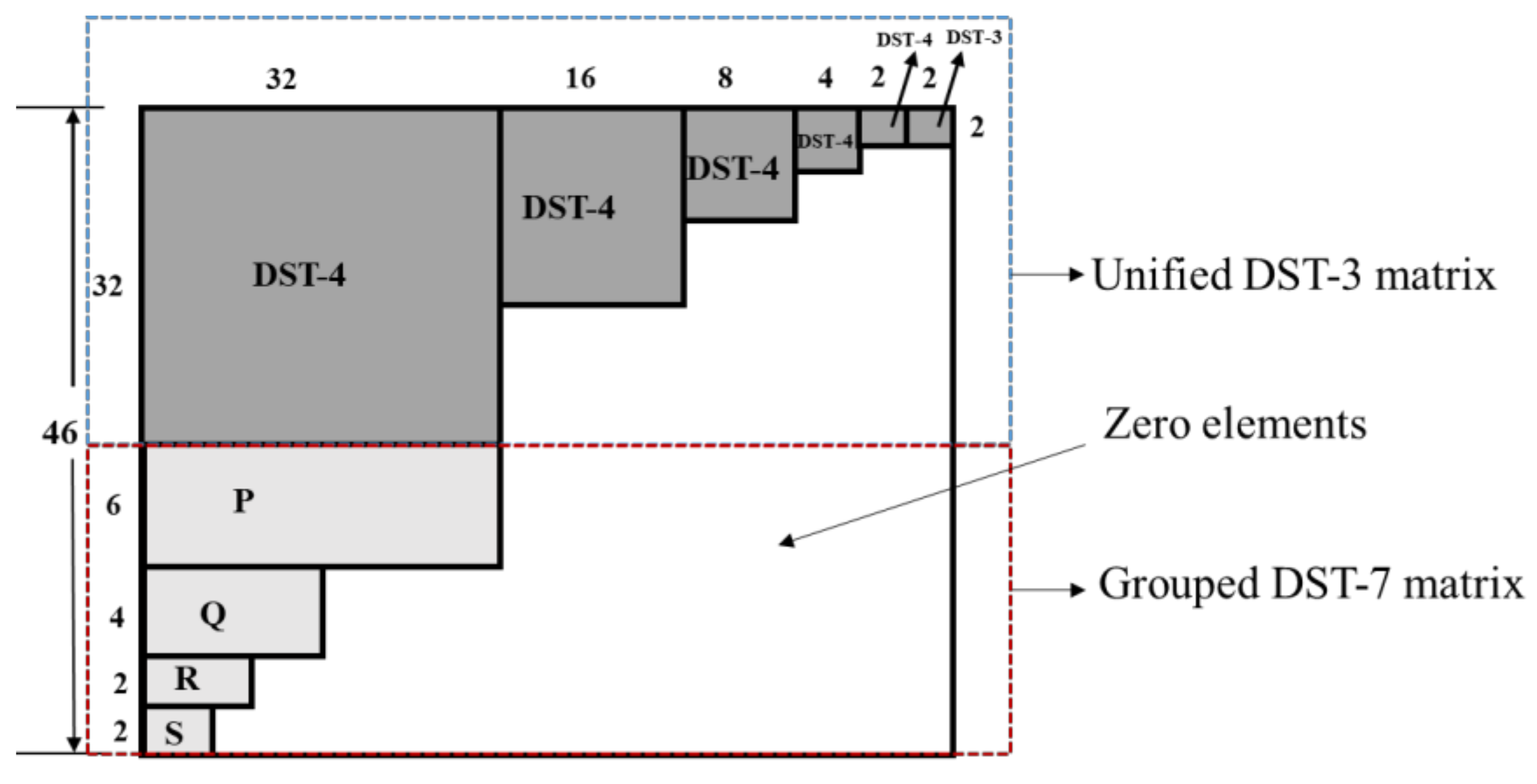
Figure 1 shows the proposed common sparse unified matrix, composed of two parts: Unified DST-3 matrix (
U) and grouped DST-7 matrix. The
U matrix is composed of different block sizes of DST-4 and is used to derive different block sizes of DCT-2 transform kernels. It stores 1368 elements with 8-bit precision. Similarly, grouped DST-7 is used to derive different block sizes of DST-7 transform kernels. It comprises
P,
Q,
R, and
S matrices, which are different selected rows from 32-point, 16-point, 8-point, and 4-point DST-7 transform kernels. It stores 280 elements with 8-bit precision. Hence, the total memory allocation must be appointed for only 1648 elements for the overall common sparse unified matrix.
The remainder of this paper is organized as follows. In
Section 2, the proposed MTS kernel derivation method is described. In
Section 3, the experimental results are provided, and the concluding statements are provided in
Section 4.
2. Proposed Common Sparse Unified Matrix
Figure 1 shows the proposed common sparse unified matrix. It comprises two parts: a unified DST-3 matrix (
U) and a grouped DST-7 matrix. The unified DST-3 matrix (
U) is used to derive the different sizes of DCT-2 transform kernels, whereas the grouped DST-7 matrix is used to derive the different sizes of DST-7 and DCT-8 transform kernels, where DCT-2, DST-7, and DCT-8 are the transform kernels of MTS in VVC. The
U matrix includes 32-, 16-, 4-, and 2-point DST-4 transform kernels and a 2-point DST-3 transform kernel. Similarly, the grouped DST-7 matrix comprises rows selected from different point DST-7 transform kernels, that is, 6
32 block size
P, 4
16 block size
Q, 2
8 block size
R, and 2
4 block size
S matrices are the row elements selected from 32, 16, 8, and 4-point DST-7 transform kernels, respectively.
Note that the overall size of the proposed common sparse unified matrix is 1648 bytes (integer, 8 bit-precision). The original size of the transform kernel is 8180 bytes (integer, 8-bit precision) for storing different block sizes of DCT-2, DST-7, and DCT-8.
2.1. Unified DST-3 Matrix (U)
The proposed unified DST-3 matrix (
U) was used to derive DCT-2 transform kernels of different sizes. It stores only 1368 elements with 8-bit precision for deriving any block size of the DCT-2 transform kernel, whereas the current VVC allocates memory for 5460 elements with 8-bit precision for deriving different block sizes of the DCT-2 transform kernels. The proposed basic structure of the unified DST-3 matrix is shown in
Figure 2.
The matrix
U comprises 32, 16, 8, 4, and 2-point DST-4 and a 2-point DST-3 matrix. The remaining elements of
U were set to zero. A relationship exists between DST-3 and DCT-2 [
26], which can be expressed as Equation (6).
where
is DCT-2,
is DST-3, and
F and
S are flipping and sign change matrices, respectively. The elements in
F and
S are defined as
where
m and
n are matrix indices, and
N is the size of the matrix.
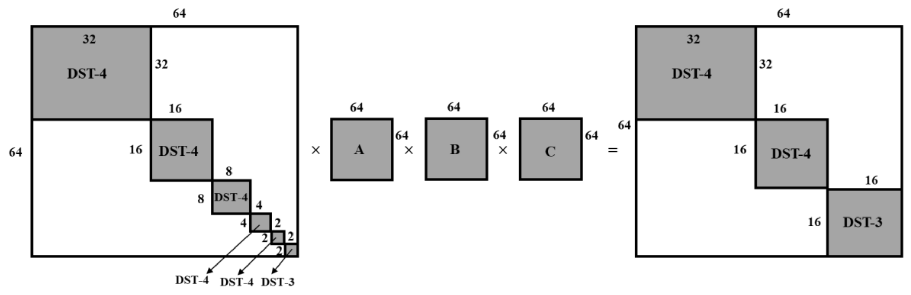
To retrieve any block size of the DCT-2 kernel, different block sizes of the DST-3 kernel are required, as in (6). As shown in
Figure 2, a 2-point DST-3 transform kernel matrix exists at the right bottom part of
U. Using (6) and the 2-point DST-3 transform kernel, a 2-point DCT-2 transform kernel can be derived. Similarly, different block sizes of DST-3 transform kernels are required to derive other sizes of DCT-2 transform kernels. To obtain different block sizes of DST-3 transform kernels from
U, the predefined 64-point unit-element matrices,
A,
B,
C,
D, and
E, are multiplied by
U.
Figure 3 shows the DST-3 derivation mechanism from unified DST-3 matrix (
U). The unit-element matrices
A,
B,
C,
D, and
E are the matrices with values of −1, 0, or 1, and their elements are defined as Equations (9)–(13), respectively.
The relation between
U and the unit-element matrices can be expressed as Equation (14).
where
is the 64-point DST-3 transform kernel,
U is the proposed unified DST-3 matrix, and
A,
B,
C,
D, and
E are the 64-point unit-element matrices. Using
U and the unit-element matrices, DST-3 transform kernels with different sizes can be obtained, which is explained using Equations (15)–(19)
where
is an
N-point DST-3 transform kernel,
represents a function that takes an
N ×
N block of the right-bottom part of the matrix, and
M,
N,
O, and
P are defined using unit elements (−1, 0, and 1) as in Equation (20).
For example, to derive the 16-point DCT-2 kernel, a 16-point DST-3 is required, as in Equation (6). First,
U is multiplied by the
A,
B, and
C unit-element matrices as in (17) in sequential order, thus leading to 32-point DST-4, 16-point DST-4, and 16-point DST-3 transform kernel matrices. Using the resulting matrices, the 16-point DST-3 matrix at the bottom right of the generated matrix is obtained. Finally, the 16-point DCT-2 transform kernel can be obtained using (6) and a 16-point DST-3.
Figure 4 shows the overall process of generation of the 16-point DST-3 transform kernel.
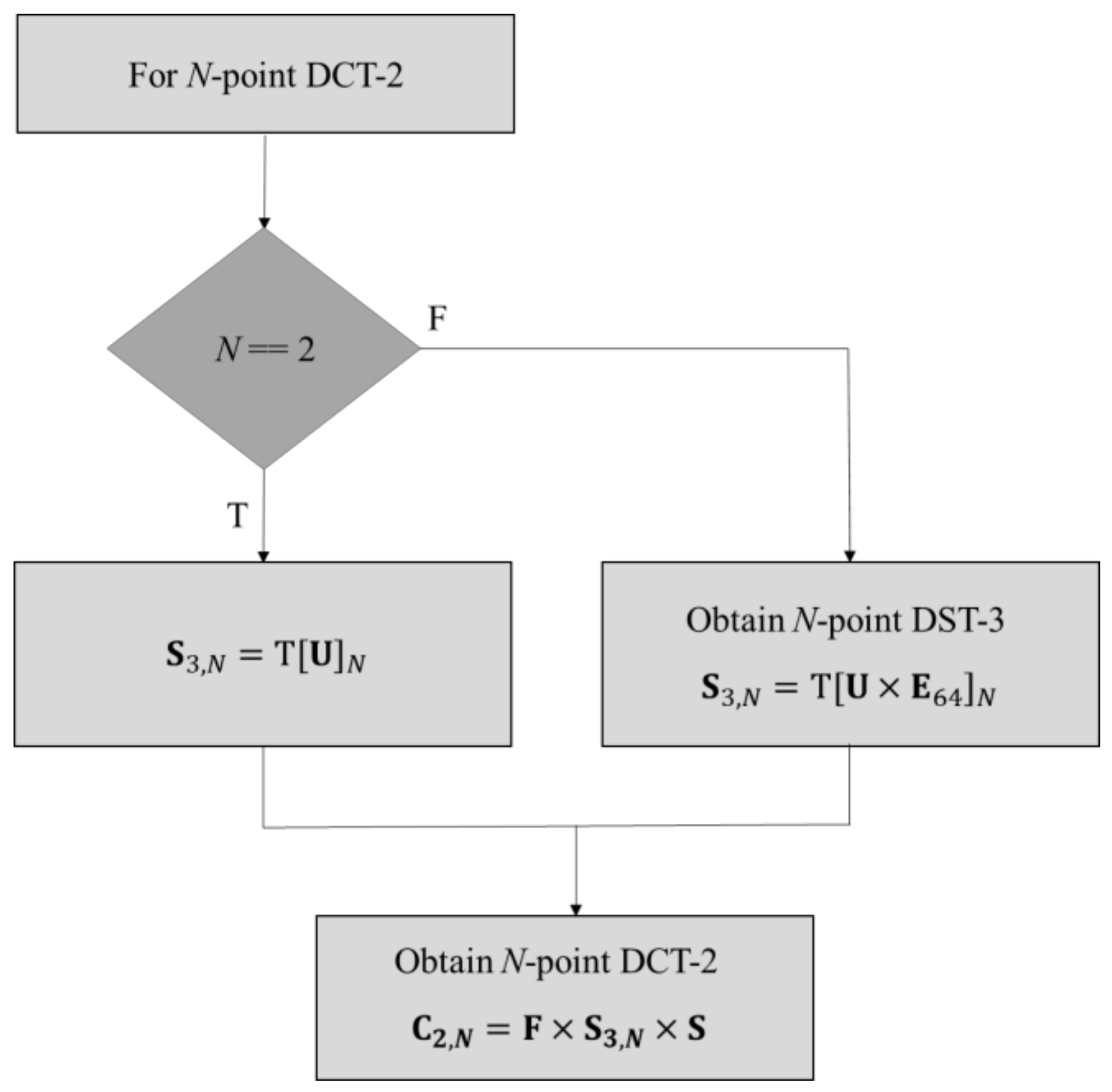
Figure 5 shows the proposed derivation of the
N-point DCT-2 transform kernel. First, the value of
N is equal to 2. If the condition is satisfied,
is obtained by the selection of a 2 × 2 block of the right-bottom part of the
U matrix; otherwise,
is achieved by the selection of the
N ×
N block of the bottom right of the matrix obtained after the multiplication of
U, and
.
represents the unit-element matrices
A,
B,
C,
D, and
E.
can be obtained by multiplying the unit-element matrices
A,
B,
C,
D, and
E, depending on
N. For example,
is calculated as
, , and
A for
N = 32,
N = 16,
N = 8, and
N = 4, respectively. Finally, the
N-point DCT-2 transform kernel was obtained using (6).
Figure 5 shows an illustration of the proposed DCT-2 transform kernel derivation.
2.2. Proposed Grouped DST-7 Matrix
To derive the full DST-7 and DCT-8 matrices with less memory, a grouped DST-7 matrix is proposed. The proposed grouped DST-7 matrix is based on the principle of storing only a few selected rows of different block-sized DST-7 transform kernels. The rows selected from the original kernel matrix are used to generate the group of elements of the respective block size DST-7 transform kernel with the help of the permutation matrix (
G) comprising −1, 0, or 1. The matrix
G is multiplied by the selected rows, resulting in a full block-sized DST-7 transform kernel. The matrices
P,
Q,
R, and
S in
Figure 1 indicate the rows for the derivation of 32, 16, 8, and 4-point DST-7 transform kernels, respectively, and they are only stored for DST-7 and DCT-8 kernel derivation, leading to a significant reduction in memory storage. The grouped DST-7 matrix is defined as a 14 × 64 matrix of the lower part, as shown in
Figure 1, and the total memory allocation is required for only 280 elements with 8-bit precision, which significantly reduces the memory sizes of the current DST-7 in VVC with 1360 elements each with 8-bit precision.
To derive the full-size 32-point DST-7 transform kernel, only six-row vectors from the 32-point DST-7 are selected, that is,
P =
T and can be base vectors for each group of DST-7 matrix in the proposed method. Similarly, for the derivation of full-size 16, 8, and 4-point DST-7 transform kernels,
Q with four rows,
R with two rows, and
S with two rows, that is,
Q =
T,
R =
T, and
S =
T, are selected from 16, 8, and 4-point DST-7, respectively and are regarded as the base vectors. Note that
represents the
i-th row of DST-7. Using a few selected rows and
G, the full-size DST-7 transform kernel can be derived by retrieving the row vectors of each group.
Figure 6 shows an illustration of kernel derivation using a grouped 32-point DST-7 matrix. As shown in
Figure 6, the row vectors of
P in the grouped DST-7 matrix are used to derive the row vectors of the DST-7 kernel in each group.
Figure 7 shows the details of the derivation process of the kernel for each group. The 0-th group is taken as an example, and the other groups follow the same process using different row vectors of matrix
P.
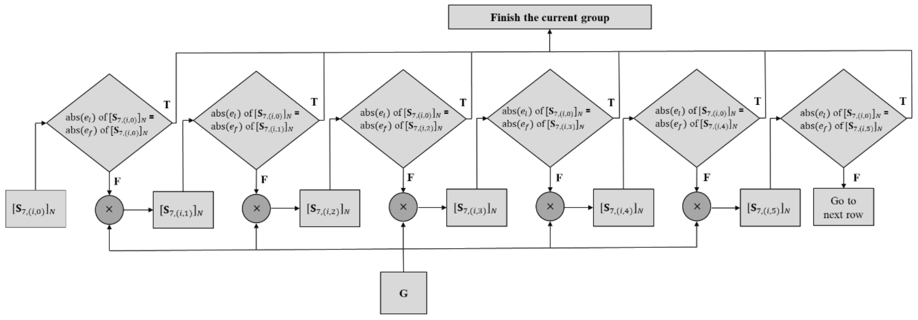
In
Figure 7,
denotes the
j-th row vector of the
i-th group for the
N-point DST-7. In the proposed method, matrix
P comprises only the 0-th row vectors of the
i-th group of the
N-point DST-7. First, the 0-th row vector
from
P is obtained from the
i-th group of DST-7. Subsequently, the absolute values of
and
, which are the last (the rightmost) and first (the leftmost) elements in the row vector, are compared. If these two absolute values are identical, the row vector can be one row of the DST-7 kernel with the same index as stored in
P. Otherwise, the row vector is multiplied by
G and a comparison of
and
in the resulting row vector is performed as in the previous step. If the first element in each row is a negative value, then the sign of every element in each row is altered. It should be noted that
G is designed such that the absolute value of the first element in the previous row equals the absolute value of the last element of the next row vector after multiplying with
G. This process is repeated until the end of the last row vector of the current group.
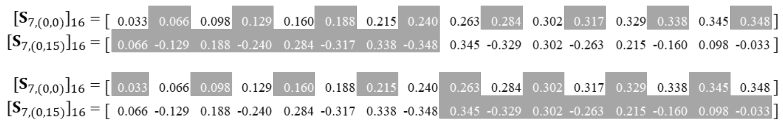
Figure 8 shows a 16-point DST-7 transform kernel derived using
Figure 7, and the elements in each row vectors are perfectly matched with the definition of DST-7 in (5). Similarly, 32-, 8-, and 4-point DST-7 can be derived using
P,
R,
S, and
G matrices, which are defined according to the size, which will be discussed in the next section.
For the derivation of the full-size 16-point DST-7 transform kernel, only four rows from the 16-point DST-7 are selected, that is, Q = T and can be used as base vectors for each group of DST-7 matrix in the proposed method.
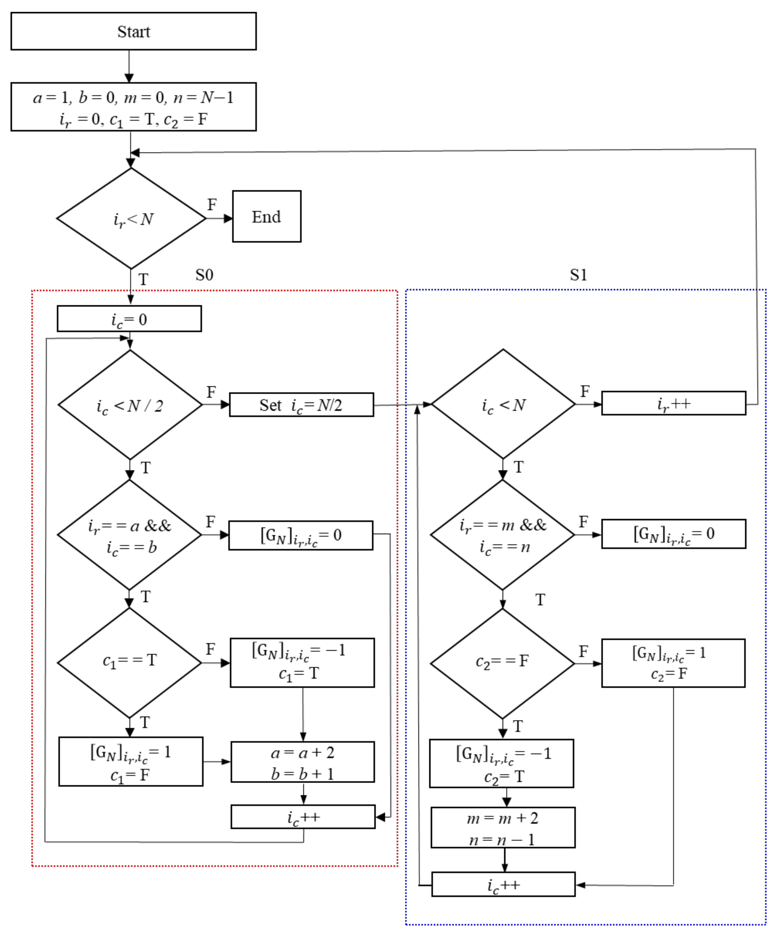
2.3. Permutation Matrix (G)
The permutation matrix
G plays a crucial role in the derivation of the DST-7 transform kernel using the proposed grouping algorithm, as mentioned in the previous section. The process of deriving
G in the proposed method is described in
Figure 9, which shows the first group of 16-point DST-7 transform kernels represented with floating-point elements, where
is only stored in matrix
Q in the common sparse unified matrix shown in
Figure 1.
The elements between the consecutive rows in the group are observed with specific patterns that appear based on the characteristics of DST-7 kernels.
Figure 10 shows the patterns of the elements in consecutive rows. As shown in
Figure 10, elements in the odd column (1st, 3rd,…) of the 0th row (
) are repeated in the left-half column in the next row. The elements in the right-half column are copied from the elements of even columns (0th, 2nd,…) in the previous row vector in reverse order.
Thus, this relation can be described in Equation (21).
Based on
Figure 7, (21) is the next row vector, composed of two parts,
and
.
and
represent the left and right halves of
.
is derived using (22), where elements in the odd column (1st, 3rd, …) of the 0th row (previous row) are selected.
is derived using (23), where elements in the even column (0th, 2nd, …) of the 0th row (previous row) are selected and substituted in a reverse way. Note that
denotes the element in the
k-th column and
j-th row vector of the
i-th group for
N-point DST-7.
where
n is the integer value,
N/2
< n > 0.Hence, a change of one element in the row vectors in a group may affect the other elements of the other vector of the same group.
Figure 10 shows an example of patterns observed between two consecutive row vectors of the 16-point DST-7 transform kernel. From the patterns,
G comprising −1, 0, and 1 can be derived.
Figure 11 shows the
G matrix based on the pattern in
Figure 10 for deriving the DST-7 transform kernel.
As shown in
Figure 11, a smaller
G can be embedded into a larger
G with identical patterns of element values.
Figure 12 shows an algorithm for obtaining the matrix. Even if the memory size of
G in
Figure 11 accounts for 256 bytes, there can be a case to derive
G on the fly using the algorithm shown in
Figure 12, not using static memory to save
G.
As shown in
Figure 12, the algorithm comprises two parts for the left column (S0) and right column part (S1) of
G. First, variables used for the algorithm are initialized and the size (
N) of the kernel matrix to derive is set. Then, variables
a and
b are initially set to 1 and 0, which will be used as initial values of the left column (S0) part of
G.
and
represent the row and column indices of
G, respectively. The index value of
was initialized to 0. First, the condition is checked if the
index value is less than the size
N. If this is true, then the process is divided into two columns, the left column (S0) and right column (S1); then, the
index value is initialized to 0 else, the process terminates.
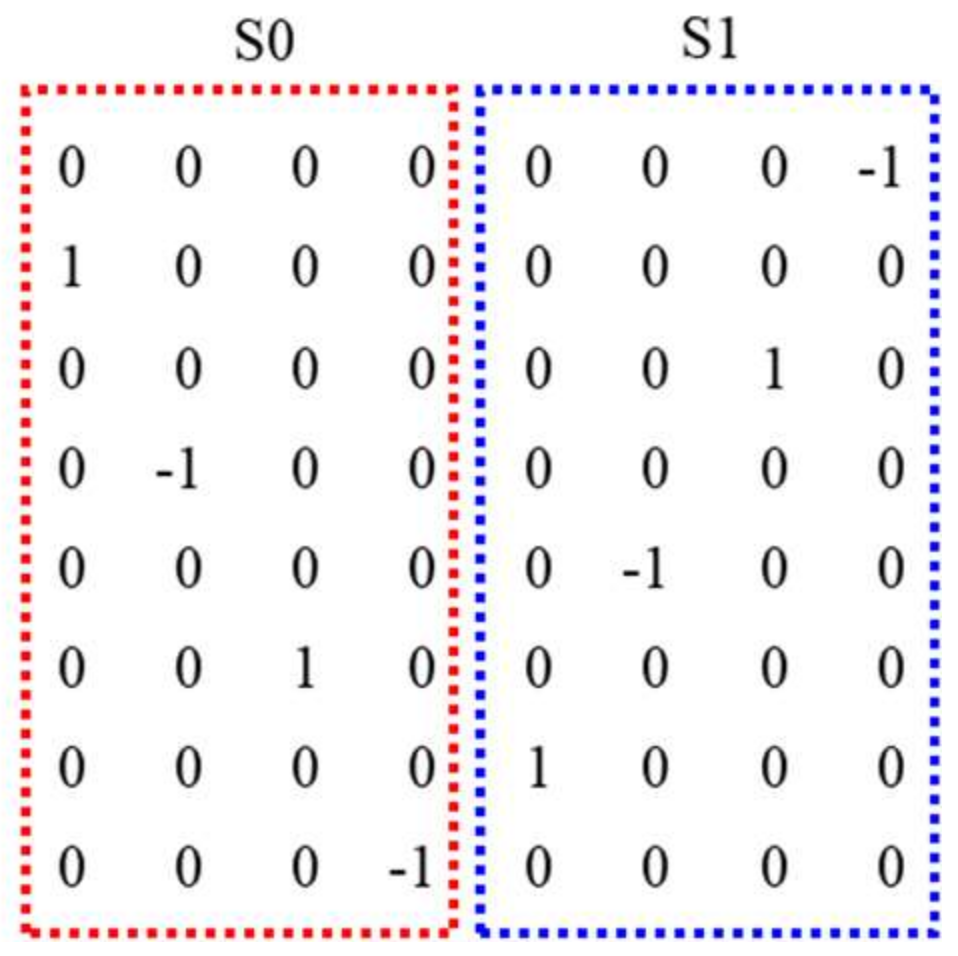
Thus, the index value is checked if it is less than half of the value of N. If the condition defined is satisfied, then and corresponding to the respective a and b variables are checked. Variables a and b are set only for the S0 of the G matrix. The value of the permutation matrix at the respective location is set to 0 if the checked condition is false, is incremented by 1, and looped back to the condition, where the index value is checked for whether it is less than half of N. If the checked condition holds true (T), is checked for whether it is true (T) or false (F). If is false, then the value is set to −1, and is set to true. Otherwise, the value of is set to 1, and is set to false. Subsequently, the value of a is incremented by 2, and the value of b is incremented by 1. After setting the values of a and b, is incremented by 1 and finally looped back to the condition where the index value is checked whether it is less than half of the value of N.
For the right column (S1) part of G, variables m and n are used, whose initial values are set to 0 and N−1, respectively. If the condition, where index value is checked to be less than half of N is false, then the value of is set as half of N. Further, the index is checked to determine whether it is less than N. If the condition is false (F), then the index value is incremented by 1 and looped back to the condition, where is less than N or is not checked. However, if the condition exists (T), then the index equals m and the index, which equals n, is checked. If it is false, the value of is set to 0. Otherwise, the condition is further checked for whether it is false. If is false, the value is set to 1, and is set as false; thus, the index is incremented by 1 and looped back to the condition where is checked to determine whether it is less than N. Otherwise, the value is set as −1 and is set as true, the value of m is incremented by 2, and that of n is decremented by 1. Finally, the value of the index is incremented by 1 and looped back to the condition where the index is checked to determine whether it is less than N.
An example of the splitting of S0 and S1 in the
G matrix for
N = 8 is shown in
Figure 13.
2.4. Integer Kernels with VVC Standard
Generally, the floating-point elements in the kernels are scaled up to integer elements to avoid a mismatch between the encoder and decoder in most video coding standards. Transform and quantization using resulting integer kernel matrices are implemented with integer arithmetic, which benefits the complexity of implementations and is one of the primary concerns in the standardization of VVC. Despite the benefits of integer kernels, several disadvantages exist. Orthogonality in the kernel matrix can be lost when scaled up to integer values and the magnitudes of the matrix elements should be as small as possible under the consideration of dynamic ranges for the process of transform and quantization [
26]. Nevertheless, it is known that the kernel similarity between the derived kernel and original kernels is more important than orthogonality when quantization is applied to transform the coefficients. Thus, it is unnecessary to maintain kernel orthogonality at the expense of kernel similarity. By reflecting the requirements of transform kernels for video codec, integer kernels for every transform block are proposed and finally adopted [
15]. In this section, we show how our proposed kernel derivation method is applied for transformation with no deviation, which means the kernels derived by the proposed method are perfectly matched with the standard kernels.
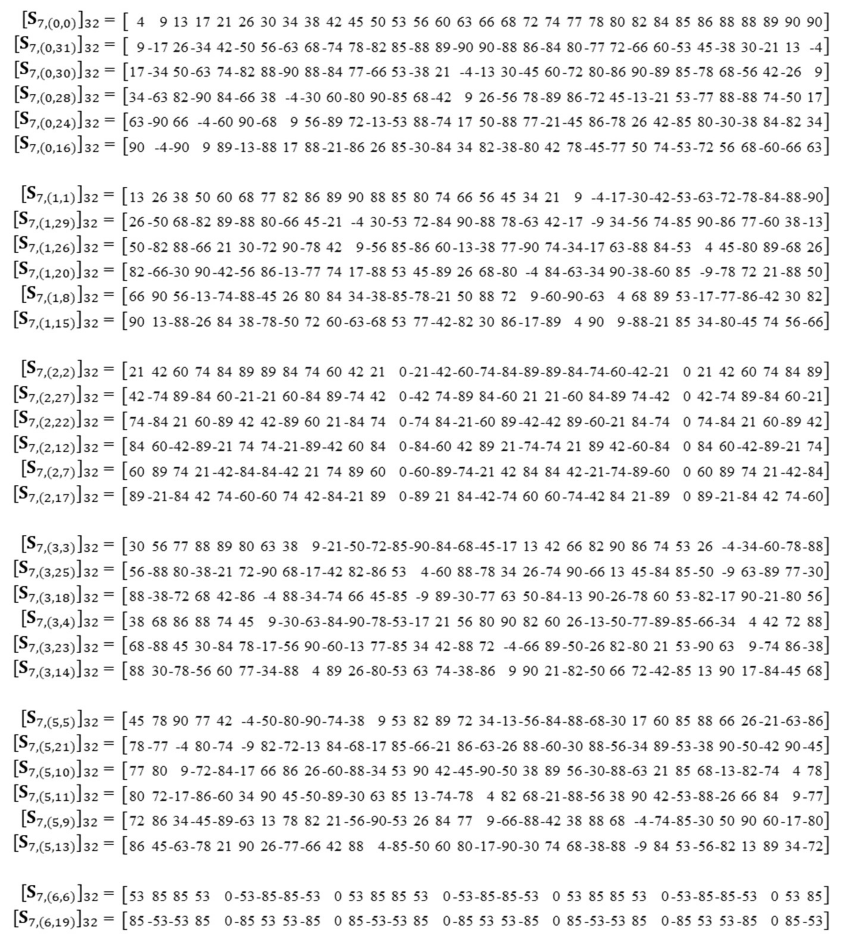
Figure 14 shows a 32-point integer DST-7 transform kernel adopted in VTM-3.0 [
27] as the standard. In
Figure 14, each row vector is shown in the order of the group. The element values in the row vectors were identical to those of the standard kernel.
As described in
Figure 7 of
Section 2.2, the absolute value of
in the current row should be identical to the absolute value of
of the next row, which is obtained by multiplying the current row vector by
G. The multiplication can be repeated until
of the base (first) row is equal to
of the row multiplied by
G. For the derivation of all sizes of DST-7, the multiplications are repeated until the end of the last vectors of the group, except for a few cases for 32-point DST-7, which are observed in the 3rd group for 32-point DST-7.
Figure 15 shows the case shown in the 3rd group for the 32-point DST-7.
As shown in
Figure 15,
is obtained after the multiplication of
and
G. Because
of
equals
of
, the algorithm for the current group is complete, as shown in
Figure 7. Thus,
,
and
for the full-size DST-7 kernel cannot be obtained using the proposed algorithm. This only happens when the element values are scaled up to make the element values of the kernel integer. To address this problem for integer kernels of DST-7, especially for the 32-point kernel, two approaches are proposed in our method. The first method is to tune
of
from 88 to 89 without considering the sign value, and by tuning the value, the case of stopping the algorithm in
obtained after the multiplication of
and
G can be removed, resulting in a full-size 32-point DST-7 transform kernel.
Figure 16a shows this procedure. Similarly, the second method is to tune the 3rd element of the value of
from 88 to 89 without considering the sign value, as shown in
Figure 16b. By tuning the values, the related values in the other vectors are changed by the proposed algorithm, accordingly.
Finally, once all sizes of DST-7 kernels are derived, DCT-7 and all DCT-8 transform kernels can be easily derived using relation Equation (24) as
where
and
are the DCT-8 and DST-7 transform kernels, respectively, and
S and
F are the sign-changing and flipping matrices, defined in (7) and (8), respectively.
2.5. Application of the Proposed Method to the DST-7/DCT-8 Fast Algorithm in VTM
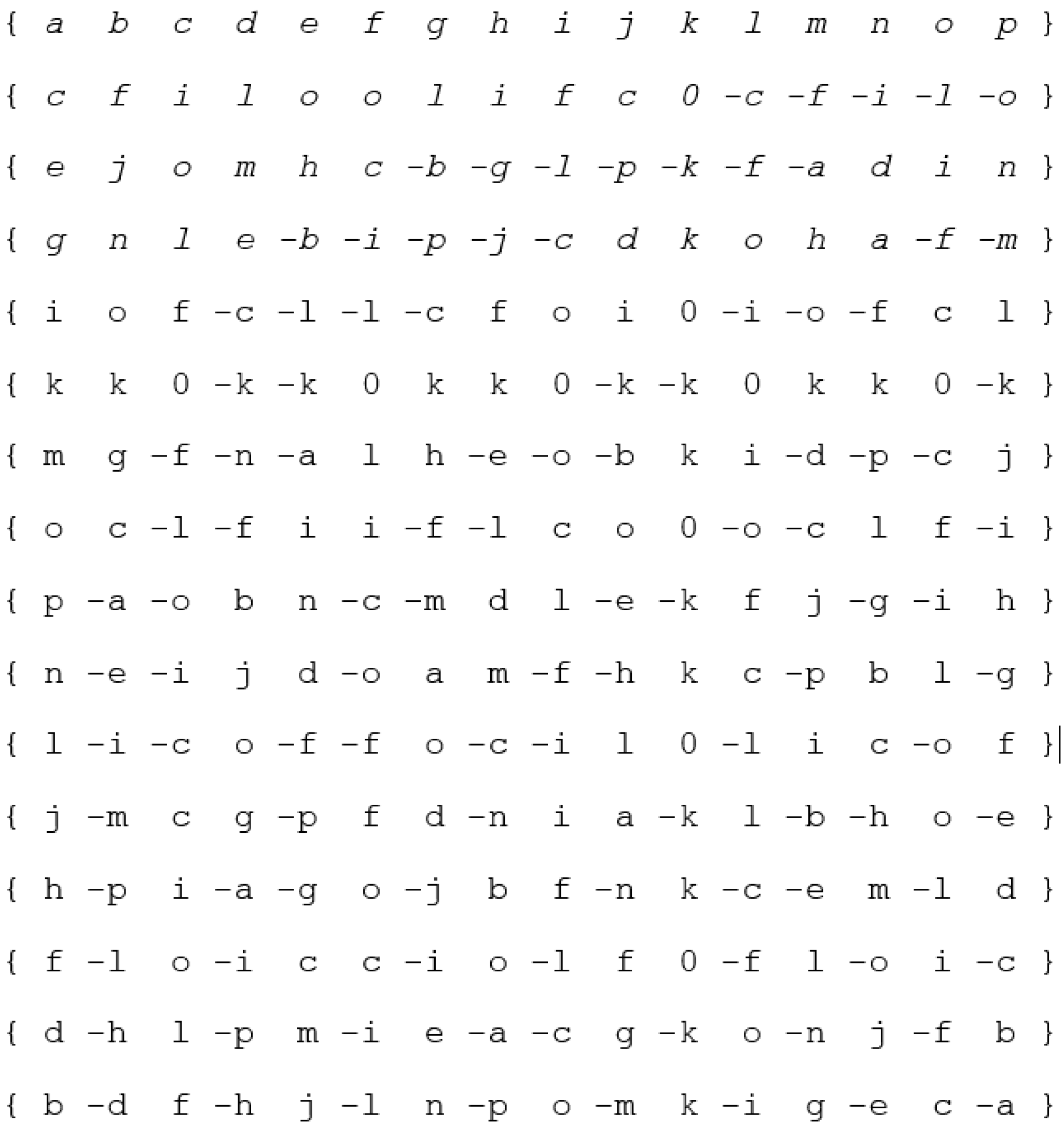
In Equation (23), a fast DST-7/DCT-8 algorithm with dual support was introduced and adopted in VTM-3.0. The fast algorithm is based on three different features for integer
N-point DST-7/DCT-8 transform kernels shown in
Figure 17, which can be defined as
Figure 17.
Where {a, b, c, d, e, f, g, h, i, j, k, l, m, n, o, p} are the N-point unique integer numbers for the 16-point DST-7 kernel. Assume that the output vector is obtained by multiplying the input vector with the transform kernel C, that is, ().
Feature #1: It is observed that the sum of several (2 or 3) numbers is equal to the sum of several (1 or 2) numbers. The elements l, m, n, o, and p are obtained by (a + j), (b + i), (c + h), (d + g), and (e + f), respectively.
To calculate
y0, instead of performing vector-by-vector multiplication that requires 16 multiplications, the following alternative implementation is computed as shown in Equation (25):
which requires 10 multiplications.
Feature #2: This is based on the feature that some elements in a row vector of DST-7 are symmetrically mirrored with each other. For example, the second vector {c, f, i, l, o, o, l, i, f, c, o, c, f, i, l, o} in Figure xx with only c, f, i, l, and o elements.
To calculate
y1, instead of performing vector-by-vector multiplication that requires 16 multiplications, the following alternative implementation is computed, as shown in Equation (26):
which requires five multiplications.
Feature #3: This is based on the basic vectors that contain very few numbers (1 or 2) of distinct values without considering sign values {k, k, 0, −k, −k, 0, k, k, 0, −k, −k, 0, k, k, 0, −k}. To calculate y5, instead of performing vector-by-vector multiplication that requires 16 multiplications, the following alternative implementation is computed as shown in Equation (27):
which requires one multiplication.
The major drawback of the fast algorithm [
28] for DST-7 transform in VTM3.0 is that one feature out of the mentioned three features has to be applied in each row. However, once a feature is selected for the basic vector such as
, , and
, the same feature is applied to vectors belonging to the same group. Hence, the proposed method follows “one group one feature” and removes the matching of a single feature among the three features in each row.
For example, in the first row, a vector of DST-7, Feature #1 is applied, whereas in the second-row vector, Feature #2 is applied. Similarly, for the other rows, a single feature out of three features was applied. Initially, before applying the feature in each row vector, we were unaware of the feature to be applied in the respective row vector. Consequently, we need to check if the respective row vector follows Feature #1, #2, or #3 such that the single matched feature is applied. For a larger matrix, the number of row vectors is large; therefore, for each row, we have to manually check if each row follows Feature #1, #2, or #3, which is time-consuming.
Based on the proposed grouping method, only for the base row vector, a feature out of three features is selected manually, and the row vectors that depend on the base row, that is, each grouped row vector, follow the same feature that is applied to the based row vector.
Figure 18 shows the application of the proposed 16-point grouped DST-7 transform to the fast algorithm in VVC. Feature 1 can be applied to the 0th and 2nd groups. The elements in the
l,
m,
n,
o, and
p columns are obtained by the summation of the column elements such as (
a +
j), (
b +
i), (
c +
h), (
d +
g), and (
e +
f), respectively, of the 0th and 2nd groups. Feature #2 is applied to the 1-st group where column elements in
f,
g,
h,
i, and
j are mirrored values of column elements
e,
d,
c,
b, and
a, respectively. Similarly, elements in
l,
m,
n,
o, and
p are mirrored in the column elements
j,
i,
h,
g, and
f with flipped signed values, respectively. Similarly, Feature #3 is applied to
as it contains only a single distinct element, that is, 77. This is possible with the help of the proposed grouping method.
3. Experimental Results and Analysis
To verify the proposed method for the transform kernel derivation for VVC, the similarities between the proposed kernels and the original kernels in VTM-3.0 [
27] were investigated by plotting the kernels in a graphical representation.
Figure 19 shows the comparison of the transform kernels. It can be seen that the derived transform kernels are almost perfectly matched with the original transform kernels. As described in
Section 3, only a few integer elements in the 32-point DST-7 kernel are tuned from the original kernels to obtain full transform kernels. Thus, it can be inferred that the proposed transform kernels are more likely to have identical coding gains.
Experiment for verification of the proposed method were performed on the VVC reference software, VTM-3.0 [
27], using CTC conditions [
29]. The PC for simulation was Centos 7 OS with an Intel
® Xeon
® Silver 4114 CPU @ 2.20 GHz processor with 200 cores and 156 GB of RAM. Parallel processing is turned off to precisely measure the encoding and decoding complexity in the execution time. The coding performance was measured in BDBR (%) [
30].
Table 2 shows the experimental results of the proposed method. As shown in
Table 2, the coding performances of the proposed method are almost identical to the original VTM3.0 for all configurations. This is because the similarity of the proposed transform kernel with the original transform kernel is almost perfect.
Table 3,
Table 4 and
Table 5 show a comparison of the results of the proposed method for the AI, RA, and LDB configurations [
31], respectively.
Although COT [
21] provides better coding gain, it fails to provide a 64-point DCT-2 transform kernel, as some rows of 64-point DCT-2 transform kernels are removed and replaced with selected row values of DST-7/DCT-8 transform kernels [
21].
In addition, [
21] used five transform kernels, that is, DCT-2, DST-7, DCT-8, DST-4, and DCT-4. Similarly, the unified matrix [
23] presented excellent coding gain; however, the higher resolution class sequences, Classes A1 and A2 have higher coding loss. This results from the deviation of the proposed mathematically derived transform kernels with the original transform kernels. In [
24,
25], owing to the mismatch in the proposed transform kernels with original transform kernels, coding losses can be seen. In our proposed method, no coding loss is observed in higher-resolution class sequences. The overall result showed a minor gain of 0.02% in the U-chroma. This is because the proposed transform kernels were in good agreement with the original transform kernels, as shown in
Figure 19.
Table 4 shows the overall experimental results of RA using the VTM-3.0 reference software under the CTC conditions. Coding loss can be seen in [
23,
24,
25] but [
21] showed less significant luma gain. Similarly, the proposed method showed no significant loss compared to the other methods.
Table 5 shows the overall experimental results of LDB using the VTM-3.0 reference software under the CTC conditions. [
21,
23,
25] showed higher coding loss, whereas the proposed method showed a 0.27% coding gain in V-chroma and negligible loss in U-chroma.


