Abstract
With the ageing infrastructure and fast-growing demand faced by utilities worldwide, voltage uprating is one of the most effective solutions and strategic approaches in asset management decisions. In this study, a systematic voltage uprating method is used to propose the new voltage level, based on the existing transmission lines’ physical structure, by utilising appropriate techniques. Prior to work conducted, the existing 132 kV transmission line was first examined in terms of the clearances and the components attached, and a technical issue on the clearance under still air was found to be a significant concern, particularly on phase-to-earth arrangements. Next, the proposed techniques and processes, by increasing the insulation strength and improving air conductor clearances, were used for the individual existing 132 kV transmission tower. The proposed voltage uprating of the 132 kV transmission tower comprehensively examines phase-to-earth under normal and extreme wind conditions based on electrical clearance requirements for 275 kV transmission lines. The proposed uprating model was then simulated using the Finite Element Method (FEM)-based commercial software under several lightning conditions, i.e., various basic lightning insulation levels (BIL) and different flashover mechanisms, taking into consideration still air and wind conditions for the voltage profile and its insulation strength analyses. The study found that the voltage profile condition for the proposed voltage uprating model was able to withstand its BIL under all conditions and thus satisfied the electrical requirement needed.
1. Introduction
All over the world, we are faced with a growing cumulative population, the development of large industries, and the evolution of the advanced transportation sector, which have been steadily contributing to the increasing demand for electricity. This is leading to pressure on electric utility operators to provide the required demand for electricity as the years goes on. The new development of a transmission system is one of the opportunities for utilities to sustain and stabilise a country’s rapid growth. However, issues are associated with the new development of transmission lines involving technical, environmental, and financial feasibility [1,2,3,4,5,6]. Some of the concerns that can be critically relevant in the permitting process are transmission lines are visual impact, property devaluation, suspected health effects from EMF, impact on land use, impact on ecological systems, and environmental impact of the transmission line construction and maintenance [7,8,9]. The environmental aspects are a significant concern issue in the new transmission system development as it mainly involves exploration of gazetted areas and forest reserves, especially in Malaysia.
Therefore, increased utilisation of existing transmission lines is of interest to electric utility operators throughout the world in order to accommodate the increasing electricity demand. According to [10], there are several options of asset management decision to increase utilisation of existing transmission lines such as uprating, upgrading, refurbishment, or life expansion and expansion. In recent years, various studies have been carried out to increase the power transfer capability with the uprating options. Uprating is known as increasing the electrical characteristics of a transmission line due to higher electrical capacity [10]. There are several uprating methods that have been implemented around the world by either increasing the current carrying of its conductor or by increasing its operating voltage level [11,12]. The uprating methods are, namely, current and voltage uprating. According to Conseil International des Grands Réseaux Electriques (CIGRE) Technical Brochure 353 reveals that the current uprating techniques include installing higher capacity of conductors, additional conductors, active line rating systems, increasing conductor tension, adopting probabilistic ratings, and redesigning high surge impedance, meanwhile, voltage uprating techniques include, for instance, increasing electrical strength and conductor attachments [10]. A previous study in [13] revealed that the voltage uprating significantly delivered much higher power transfer due to the reduction of electrical losses rather than current uprating.
Voltage uprating is one of the most effective solutions and strategic approaches to asset management decisions. It could be completed at substantially less cost than the new development of transmission lines, and it is considered to have a shorter lead time [13]. In previous work [14], multiple techniques have been used to uprate the existing 41.6 kV sub-transmission lines to 115 kV with minor modifications, such as re-insulation, reconductoring, midspan spacer, and a pole-top bracket for centre phase installations in order to resolve technical issues (i.e., electrical clearance requirement). A previous study on voltage uprating of 275 kV existing transmission line revealed that the modification of phase assembly insulation fulfilled electrical clearances of the 400 kV line and its transmission line ready before the peak winter demands [15]. In Japan, the existing 66 kV transmission line faced two main technical issues to uprate to 154 kV line that involved clearance around tower and insulation between conductors in span, and it was found that the proposed techniques of insulator supported jumper and phase-to-phase jumper succeeded to fulfill the electrical clearance requirements [16]. According to [10], the different technique of voltage uprating was used by converting from double circuit to single circuit in order to achieve adequate safety margin of electrical clearances from the original level voltage of 230 kV to new level voltage of 500 kV lines requirement. Meanwhile, another study reported that a major challenge for voltage uprating is to provide sufficient air clearance for the new level of voltage, however, this study found that by adjusting insulator length and its creepage distance had achieved sufficient electrical clearances of the new voltage lines’ needs [13].
In recent years, the country of Malaysia has been growing steadily, especially in several leading sectors, and has indirectly required sufficient power supply capability. On the other hand, transmission lines are the backbone for power transfer and one of the crucial assets for electric utility operators to maintain and be fit to operate [17]. However, it was noticed that the transmission lines are fully exposed to environmental factors, including transient overvoltages, i.e., lightning activities [18,19,20,21]. This is portrayed where adverse weather, which represents lightning-related events, is one of the causes of transmission line interruptions.
In Malaysia, a study regarding the uprating of the 132 kV transmission line proposed current uprating techniques. It was mainly focused on the reconductoring, i.e., conductor type, to improve conductor sag [22]. However, there is still a lack of knowledge regarding the voltage uprating of the existing transmission lines in Malaysia. In this paper, the main contribution is to propose the voltage uprating method associated with techniques and processes on the existing 132 kV transmission lines. In this study, a significant concern of voltage uprating is a technical issue, including a phase-to-earth electrical clearance. The study demonstrated that the voltage uprating of the existing 132 kV transmission line is likely to be considered a minimal structural modification in order to fulfill electrical clearances requirements. However, it is worth mentioning that voltage uprating is a preeminent option rather than new transmission line development. The FEM simulations were carried out on the proposed voltage uprating model by considering transient overvoltages and power frequency magnitude to examine the withstand capabilities under various conditions (i.e., still air and wind conditions) on the insulation strength. The simulations results were compared with the estimated critical flashover voltage (CFO) as the benchmark.
2. Methodology
2.1. The Overall Framework of the Voltage Uprating of 132 kV Transmission Line in Malaysia
The overall framework of the studies comprises two main stages, including the model proposal and comprehensive simulation of the proposed model, as illustrated in Figure 1. The increasing utilization of existing transmission methods, techniques and processes were applied in this study. The proposed voltage uprating of the existing 132 kV transmission line was then validated by fulfilling the required electrical clearances for the 275 kV transmission line. Then, the proposed model was simulated by using the FEM commercial software, and the results were analyzed by satisfying the estimated CFO.
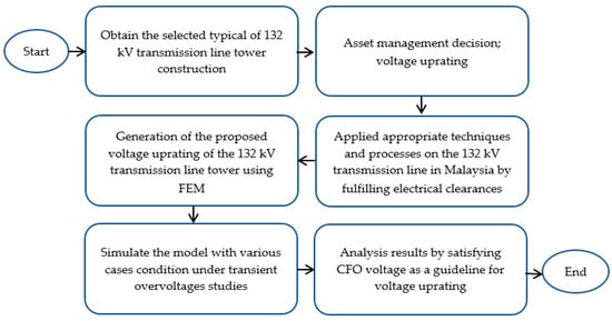
Figure 1.
The model proposal framework simulates and analyses the voltage uprating of 132 kV transmission lines in Malaysia.
2.2. Descriptions of 132 kV Transmission Line in Malaysia
The transmission line system chosen for this study involved was a 132 kV transmission line system. Figure 2a shows a typical 132 kV transmission tower construction model in Malaysia, known as type 23L steel lattice. The height of this lattice tower was 28.22 m, and the transmission line system is assumed to be located on flat terrain with a typical span length of 300 m. The line was strung with twin 300 mm2 aluminium conductor steel reinforced (ACSR) code-named ‘Batang’, its outside diameter is 24.16 mm, and bundled conductors are separated at 400 mm each. Meanwhile, the earth wire was a single 160 mm2 optical ground wire (OPGW) for each circuit, and its outside diameter was 12.20 mm. The typical suspension insulator string had ten toughened glass insulator discs and an overall string length of 2009 mm, including fittings at the top and bottom of the string. The minimum electrical clearances for phase-to-phase, phase-to-earth and phase-to-ground were 3.57 m, 1.52 m and 16.67 m, respectively. Figure 2b shows the details of electrical clearance under still air condition for a typical 132 kV transmission line system.
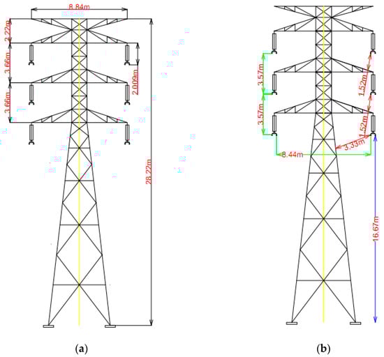
Figure 2.
The typical of the 132 kV transmission tower in Malaysia; (a) type 23 L of tower geometry, and (b) available electrical clearance.
2.3. Voltage Uprating for the Typical Tower of 132 kV Transmission Line Processes and Its Analyses
Figure 3 depicts the processes in this voltage uprating for the transmission line system in Malaysia. In order to achieve voltage uprating, associated techniques and processes against electrical clearance requirements were used in this study. The proposed techniques of voltage uprating for existing transmission were divided into two parts. The first proposed technique was by increasing insulation strength, while the second proposed technique improved conductor air clearance. All proposed techniques and processes were measured to fulfill electrical clearances requirements under still air and windy conditions. The minimum air clearances required for each voltage level are given in IEC60071 [23,24]. The minimum electrical clearances during still air and wind conditions for the 275 kV transmission line system can be seen in Table 1 and Table 2.
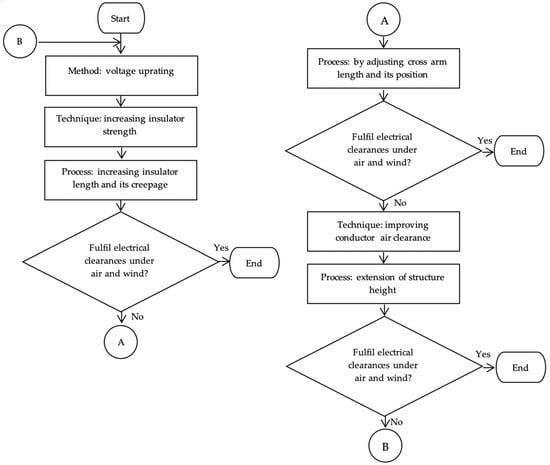
Figure 3.
Techniques and processes of the voltage uprating proposed method.
The nature of the voltage stresses that a transmission line system had experienced power frequency, lightning, and switching overvoltages [17,25,26,27,28,29,30,31]. Both transient and power frequency overvoltages stresses appear in all shapes and with different amplitudes. Each type of transient and power frequency overvoltages may occur during most types of meteorological conditions, leading to the flashover strength differently [32]. In this study, the requirement of electrical clearances (i.e., phase-to-earth, phase-to-phase and phase-to-ground) under still air conditions subjected BIL of power frequency and transient overvoltages. The transmission line was exposed to environmental factors and it had experienced normal insulator string swing leading to reduction of phase-to-earth clearance, however, the movement of insulator string under normal wind conditions is negligible. Thus, the requirement of electrical clearances of normal wind conditions is considered as under still air condition. For extreme wind conditions, insulator string experienced 57° swing angles, which are significant decrements of insulation strength (i.e., phase-to-earth) that may occur flashover under the normal operating voltage. The magnitude of the power frequency voltage is much lower than transient overvoltages, thus, it is essential to examine the BIL of power frequency voltage [33].

Table 1.
Requirement of electrical clearance under still air condition [13,23,34].
Table 1.
Requirement of electrical clearance under still air condition [13,23,34].
| BIL for 275 kV Line (Highest System Voltage 300 kV) | Minimum Clearance (m) | ||
|---|---|---|---|
| Phase-to-Earth | Phase-to-Phase | Phase-to-Ground | |
| Power frequency (300 kV) | 0.51 | 0.83 | 7.00 |
| Switching impulse (850 kV) | 1.80 | 2.60 | |
| Lightning impulse (1050 kV) | 1.90 | 2.10 | |
Table 2.
Requirement of electrical clearance under (a) normal, and (b) extreme wind conditions [33,34,35].
Table 2.
Requirement of electrical clearance under (a) normal, and (b) extreme wind conditions [33,34,35].
| (a) | |||
|---|---|---|---|
| Normal Wind Condition | |||
| BIL for 275 kV Line (Highest System Voltage 300 kV) | Minimum Clearance (m) | ||
| Phase-to-Earth | Phase-to-Phase | Phase-to-Ground | |
| Power frequency (300 kV) | 0.51 | 0.83 | 7.00 |
| Switching impulse (850 kV) | 1.80 | 2.60 | |
| Lightning impulse (1050 kV) | 1.90 | 2.10 | |
| (b) | |||
| Extreme Wind Condition | |||
| BIL for 275 kV Line (Highest System Voltage 300 kV) | Minimum Clearance (m) | ||
| Phase-to-Earth | Phase-to-Phase | Phase-to-Ground | |
| Power frequency (300 kV) | 0.51 | 0.83 | 7.00 |
2.3.1. Step 1: Increasing Insulation Length and Their Creepage Distance
Figure 4a shows the 132 kV steel lattice tower with 275 kV suspension string of toughened glass discs insulator type. The typical 275 kV suspension insulator string in Malaysia has 16 toughened glass discs and 2849 mm overall string length, including fittings at the top and bottom of the string. The available phase-to-phase clearances in the existing 132 kV transmission line system in still air condition show adequate electrical clearances between the phase-to-phase to uprate to a 275 kV transmission line system. In addition, it can be seen that the available minimum phase-to-ground at the bottom-section is 15.83 m which exceeds the required ground clearance by 7.0 m, as shown in Table 3. This margin should be sufficient for maximum load conditions. However, expectedly the phase-to-earth clearance does not satisfy the electrical clearance requirement in still air.
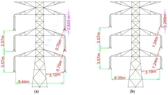
Figure 4.
The 132 kV steel lattice tower geometry; (a) with 275 kV glass discs insulator, and (b) adjusting insulator length and its creepage distance.
Table 3.
Minimum electrical clearance of 132 kV steel lattice tower with 275 kV glass discs insulator.
In order to fulfill the requirement of electrical clearance, the 132 kV transmission line towers were modified by adjusting insulator lengths and their creepage distance. As summarised in Table 4, the existing suspension string insulator length is 2240 mm, while the proposed suspension string insulator length is 1640 mm. However, its creepage distance is slightly greater than the existing suspension string insulator. The existing and proposed suspension string insulator had similar mechanical characteristics, whereas the electrical characteristic of the proposed suspension string insulator had excellent compared to the existing one. Meanwhile, the proposed suspension insulator string has 12 toughened glass insulator discs, and its overall string length, including fittings at the top and bottom of the string, was 2289 mm. Figure 4a shows the existing 132 kV transmission line with a typical 275 kV suspension string insulator.
Table 4.
Proposed suspension string insulator.
Figure 4b shows the available minimum phase-to-earth clearances of 1.24 m which are significantly not meeting the required phase-to-earth clearances of 1.80 m and 1.90 m in switching and lightning overvoltages for voltage uprating the 275 kV transmission line system. Table 5 summarised the minimum electrical clearances for the proposed model under still air conditions.
Table 5.
Minimum electrical clearance of 132 kV steel lattice tower by adjusting insulator length and its creepage distance.
2.3.2. Step 2: Adjusting Crossarm Length and its Position
The technique of modifying the crossarm length and its position was proposed to provide sufficient electrical clearances. Two towers, namely Model A and Model B, were anticipated to fulfill electrical clearances requirements and were structurally modified, as shown in Figure 5. The proposed crossarm materials were made up of fibreglass composite. Model A and Model B showed that available minimum phase-to-earth clearances are 0.83 m and 0.83 m which significantly do not meet the required phase-to-earth clearance of 1.80 m and 1.90 m in switching and lightning overvoltages 275 kV transmission line system. Table 6 shows the minimum electrical clearances for the proposed model under still air condition.
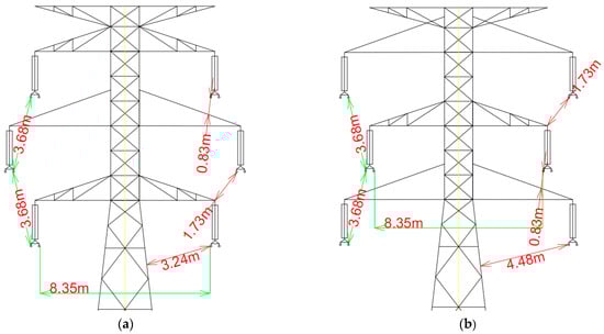
Figure 5.
The proposed model of the existing 132 kV transmission line by adjusting the crossarm length and its position; (a) Model A—midsection crossarm, and (b) Model B—top and bottom section crossarm.
Table 6.
Minimum electrical clearance by adjusting the crossarm length and its position.
2.3.3. Step 3: Extension of Structure Height and Its Analysis under Still Air and Wind Conditions
Minimal modification of the tower structure was made by increasing structure height to cater for electrical clearances under still air conditions. The top of the tower (redline) was added, expanding the structure height by 2.22 m. Meanwhile, the top, midsection, and shield cross-arms (green line) are repositioned within the existing 132 kV transmission tower structure. The proposed 275 kV transmission height is 30.44 m, as can be seen in Figure 6a.
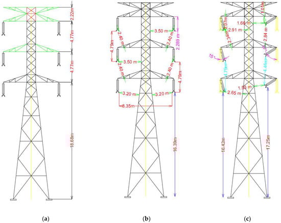
Figure 6.
(a) The proposed model of voltage uprating for 132 kV transmission tower, (b) analysis of electrical clearances under still air, and (c) wind conditions.
Therefore, the minimum available electrical clearances between phase-to-earth, phase-to-phase and phase-to-ground for the voltage uprating of the existing 132 kV transmission line under still air are now 2.40 m, 4.79 m and 16.39 m, as shown in Figure 6b. Meanwhile, Table 7 shows that the available minimum clearance requirement in the proposed 275 kV transmission line system is still air condition. It shows that there is adequate air for electrical clearances as per the requirement.
Table 7.
Minimum electrical clearance for (a) still air and (b) wind conditions.
Figure 6c shows the air of electrical clearances during the normal and extreme swing. The normal swing angle is 15°, and the extreme swing angle is 57°. During normal wind conditions, the minimum available phase-to-earth, phase-to-phase, and phase-to-ground clearances are 2.07 m, 4.79 m and 16.42 m, respectively. Meanwhile, under extreme wind conditions, the minimum available phase-to-earth, phase-to-phase, and phase-to-ground clearances during normal wind load are 1.01 m, 4.46 m and 17.25 m, respectively. It can be seen that the available clearances are sufficient to operate at a 275 kV transmission line as shown in Table 7.
2.4. Simulation Work of Voltage Uprating for 132 kV Transmission Tower
The commercial ANSYS Maxwell software was used as the simulation platform to simulate the proposed voltage uprating of 132 kV transmission tower. The software has the ability to model the component based on its properties, such as permittivity and conductivity of the materials. The proposed model of voltage uprating for 132 kV transmission line material properties is summarised in Table 8. In this study, the proposed models including a two-dimensional simplified steel crossarm, a proposed model of steel lattice body and a suspension string insulator. In this simulation, the total number of elements was 345,214, which was obtained by the adaptive meshing method. Figure 7 shows the meshing plot of the proposed voltage uprating simulation model based on finer mesh theory. In this study, it was found that the adaptive meshing method was three times repeatedly refined until the model was converged, which starts from step one passed with 204,336 elements, followed by step two passed with 265,572 elements, and then step three passed with 345,214 elements where the convergence percentage error was 1%.
Table 8.
Proposed model material properties.
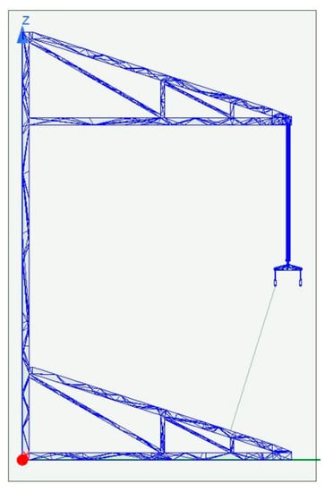
Figure 7.
The 2D meshing plot of the proposed voltage uprating model.
In this study, there were nine configurations considered, i.e., phase-to-earth at the different steel crossarms. The configurations were also considered under still air and wind conditions, respectively. The available minimum electrical clearances of L1 to L9 were defined to represent the nearest distance phase-to-earth, as shown in Figure 8. L1, L2, and L3 represent under still air conditions, while L4, L5, and L6 represent under normal wind conditions and L7, L8, and L9 represent under extreme wind conditions. However, the phase-to-earth of the top (L1, L4, L7) and mid-section (L2, L5, L8) crossarm electrical have similar distances, thus, simulations for both were conducted only once.
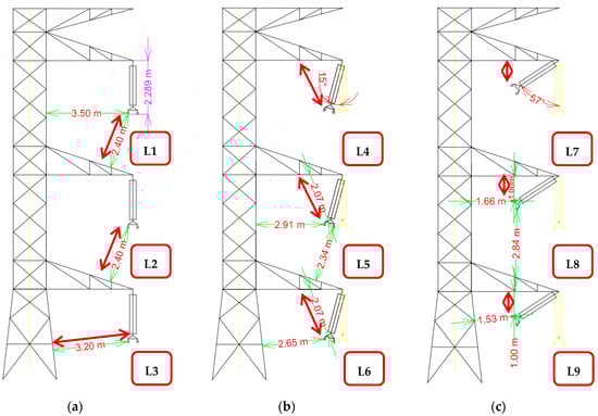
Figure 8.
The minimum phase-to-earth electrical clearances under (a) still air, (b) normal wind, and (c) extreme wind conditions.
For still air and normal wind conditions, the BIL was modelled to simulate lightning impulse conditions. In contrast, a shielding failure was also considered to simulate the condition under such an event. Meanwhile, the extreme wind condition simulated also under BIL modelled by considering the power frequency withstand voltage. Three applied voltages were considered to represent the BIL, BIL + 10% and BIL +25%, injected at the steel lattice body structure (backflashover) and phase conductor (shielding failure) as indicated in Table 9.
Table 9.
Various simulations cases study.
The two-dimensional design was chosen to evaluate the voltage profile distribution, focusing mainly on the phase-to-earth electrical clearance. The purpose of the studies is to verify the insulation strength against the transient overvoltages and power frequency that might occur within the transmission line. Therefore, the insulation strength of the crossarm and its components can be described by the CFO. The CFO refers to a 50% probability of insulation failure when the impulse waveform with the CFO peak voltage is applied to the insulation. As an excellent approximation, the CFO of insulation gaps can be derived by the length of the gaps (distance) multiplied by a CFO gradient of 560 kV/m for positive impulse polarity and 605 kV/m for negative impulse polarity [36,37]. The estimated CFO calculation is as presented in Equation (1),
The double exponential function was modeled to illustrate the BIL waveform. It was simulated based on a standard waveform of 1.2/50 µs. The BIL for both backflashover and shielding failure were modelled by using a double exponential equation as presented in Equation (2):
where u0 is the lightning peak impulse voltage, α is the wavefront attenuation coefficient, and β is the wave tail attenuation coefficient. Meanwhile, k is the correction attenuation. The BIL modelled waveform is shown in Figure 9. For both backflashover and shielding failure under case studies, the waveform was introduced and applied at the structure of the tower and phase conductor. The simulations were executed for 100 µs by considering a time step of 0.1 µs.
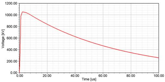
Figure 9.
The BIL waveform (1.2/50 µs).
3. Results and Discussion
The insulation strength of the phase-to-earth was a significant concern issued, and it shall experience a comprehensive evaluation. The proposed transmission model is usually exposed to transient overvoltages and power frequency, and subsequently, it could suffer from the most significant voltage and highest electrical stresses. Thus, the simulation by using FEM subjected at the front time of the BIL waveform was measured. The simulations results will comprehensively compare with the estimated CFOas the worst insulation strength benchmark before the existing transmission line adequate uprate to 275 kV transmission line.
The voltage profile at the minimum available electrical under still air (L1, L2 and L3), normal wind (L4, L5 and L6), and extreme wind (L7, L8, and L9) conditions at the top, mid, and bottom section crossarm was measured. In this study, the voltage profile overlay of the BIL, BIL + 10% and BIL + 25% at different structures of the crossarm and conditions showed a similar propagation pattern. For the backflashover cases, the voltage profile overlay of the proposed tower model under BIL, is shown in Figure 10. It is demonstrated that the highest voltage profile is initiated at the steel structure proposed tower and slightly decreases towards the phases of the conductor. It is believed that the decrement of voltage profile is due to propagating in different materials. Meanwhile, Figure 11 shows the shielding failure events in which voltage profile overlay starts initiation at the phases conductor and slowly reduces voltage stress once near the steel body structure.
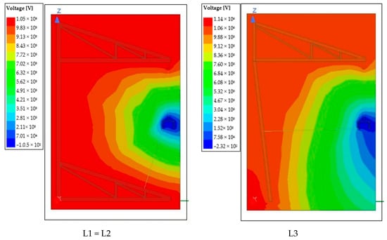
Figure 10.
Voltage profile overlay for the L1, L2 and L3 crossarm with a still air condition at BIL under a backflashover event.
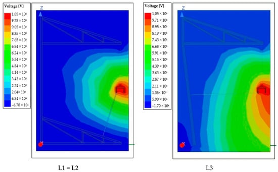
Figure 11.
Voltage profile overlay for the L1, L2 and L3 crossarm with a still air condition at BIL under a shielding failure event.
3.1. Effect of Voltage Uprating for 132 kV Transmission Tower on the Voltage Profile under Still Air
Figure 12 shows the voltage magnitude at the L1, L2 and L3 with the different voltage stresses under backflashover and shielding failure events. For the backflashover event, it was found the voltage stresses, i.e., BIL and BIL + 10% at L1, L2 and L3, remained lower than the estimated CFO of 1089 kV, as can be seen in Figure 12a. However, at 1.8 m of electrical clearance, the voltage stress at L1 and L2 for BIL + 25% remained higher than the estimated CFO for negative lightning. The voltage stress, i.e., BIL + 25% at the L3, was relatively close to the estimated CFO. The percentage of the difference on estimated CFO between simulations of voltage stresses, i.e., BIL, and BIL + 10%, was between 3.8% to 23.9%. It is believed that the insulation strength under lightning impulse is sufficient to operate of 275 kV transmission line throughout the requirement of the electrical clearance.
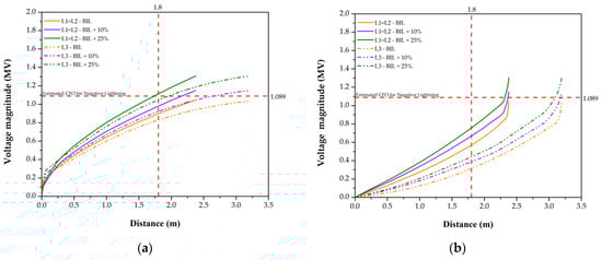
Figure 12.
Voltage magnitude due to (a) backflashover, and (b) shielding failure activities.
For the shielding failure under the case study, all L1, L2 and L3 experience significant insulation strength to withstand switching and lightning overvoltages, as shown in Figure 12b. The percentage difference of estimated CFO for negative lightning between different BIL was between 30.7% and 71.3%, as summarised in Table 10.
Table 10.
The voltage magnitude and the percentage difference between CFO and simulation results.
3.2. Effect of Voltage Uprating for 132 kV Transmission Tower on the Voltage Profile under Normal Wind Condition
The normal wind condition demonstrates a slight movement of the suspension string insulator due to environmental factors that could directly or indirectly influence the insulation strength. Malaysia’s electric utility operator has considered the 15° swing angles of the suspension string insulator as the normal wind condition. In this study, the minimum availability of electrical clearances for 15° swing angles was 2.07 m of phase-to-earth. There was a slight reduction of phase-to-earth electrical clearance between still air and normal wind condition, and its percentage difference was 13.8%.
For backlflashover under the case study, the voltage magnitude at L4, L5 and L6 under, i.e., BIL and BIL + 10% of voltage stresses are significantly lesser than the estimated CFO. At 1.8 m, the minimum electrical clearances, the BIL + 25% at L4, L5 and L6 shows exceeded the estimated CFO, as shown in Figure 13a. The percentage of increment between the estimated CFO and L4, L5 and L6 under BIL + 25% are 4.7 and 6.9%, as summarised in Table 11.
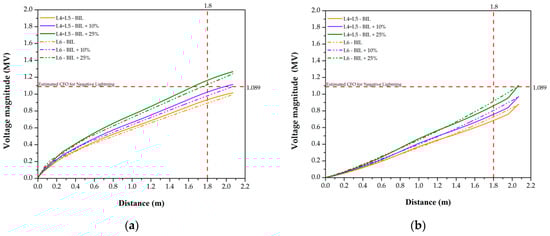
Figure 13.
Voltage magnitude due to (a) backflashover, and (b) shielding failure activities.
Table 11.
The voltage magnitude and the percentage difference between CFO and simulation results.
The voltage magnitude shows sufficient electrical clearances for shielding failure events even the L4, L5, and L6 stresses with BIL, BIL +10%, and BIL +25%. Figure 13b shows clearly at 2.0 m of electrical clearances at phase conductor to structure steadily remains lower than estimated CFO.
It is believed the reduction of electrical clearances is due to normal wind conditions, which lead slight decrease in insulation strength. However, it is noticed that the insulation strength could withstand almost 2.0 m of electrical clearances even voltage stresses up to BIL + 25% were applied.
3.3. Effect of Voltage Uprating for 132 kV Transmission Tower on the Voltage Profile under Extreme Wind Condition
Under extreme wind conditions, the string suspension swings by 57°, and its electrical clearance is significantly lower than still air and normal wind conditions. The percentage of difference in electrical clearances between under still air and extreme wind conditions is between 58.3% and 68.8% at the different crossarm sections, as summarised in Table 12. It is believed that a normal operating voltage of 132 kV uprating the transmission line could lead to flashover due to insufficient electrical clearance. The withstand voltage of the power frequency is much lower than transient overvoltages withstand voltages. Hence, the withstand voltage of the power frequency was considered in this study.
Table 12.
The voltage magnitude and the percentage difference between CFO and simulation results.
The simulations results clearly show that a similar trend of stresses and voltage profiles was obtained for all cases. Both cases under BIL, BIL +10%, and BIL +25% at different crossarm sections, none of the cases experienced high stress or having maximum voltage magnitude exceeds the CFO for the distances that could potentially give the 50% of having the flashover as can be seen in Figure 14. The insulation strength of the proposed voltage uprating of the 132 kV transmission under extreme wind conditions benefits withstanding capability. The electrical clearance of the phase-to-earth under extreme conditions is almost double the required minimum electrical clearance of 0.51 m for the power frequency needed for 275 kV transmission line operation. Meanwhile, the percentage of the difference between the estimated CFO and all cases ranges from 19.2 to 68.7 %. It is worth mentioning that the margin could be sufficient for load operating conditions.
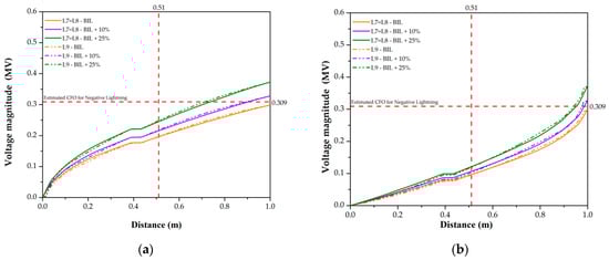
Figure 14.
Voltage magnitude due to (a) backflashover, and (b) shielding failure activities.
4. Conclusions
In conclusion, the existing 132 kV transmission lines under the case study were proposed to uprate to the new voltage level of 275 kV using the voltage uprating method. The techniques involve in voltage uprating are by increasing insulation strength and improving air conductor clearances. It is found that the voltage uprating of the existing 132 kV transmission lines fulfilled all the electrical clearances such as phase-to-earth, phase-to-phase and phase-to-ground with consideration of still air, normal wind, and extreme wind conditions. It was also revealed the electrical clearances of phase-to-phase and phase-to-ground are almost double the required minimum requirement needed for 275 kV transmission lines operation. It was believed the margin of electrical clearances ought to be sufficient for operating maximum load conditions.
A simulation study was carried out to evaluate the insulation strength of the proposed model by considering transient overvoltages, power frequency, and several conditions. Based on the simulations results under still air and normal wind conditions, it is found the voltage magnitude at BIL, and BIL +10% during backflashover events are much lower than the estimated CFO. For backflashover and extreme wind conditions under the case study, no voltage magnitude at all BIL was found to be exceeded the estimated CFO that could potentially cause flashover. Meanwhile, for shielding failure events under still and wind conditions, there is a significant difference in the percentage between the estimated CFO and all level BIL cases are ranging from 15.9 to 71.3%. It is worth to mention that the proposed voltage uprating of the existing 132 kV transmission line satisfies the insulation strength at BIL for all cases and is believed fit to operate for a 275 kV transmission line.
Author Contributions
Conceptualization, S.F.M.N. and M.Z.A.A.K.; resources, A.M.A. and M.S.A.R.; writing—original draft preparation, S.F.M.N.; writing—review and editing, S.F.M.N., M.Z.A.A.K., M.O. and N.M.Z.; supervision, M.Z.A.A.K., A.M.A. and M.O.; funding acquisition, M.Z.A.A.K., A.M.A. and M.O. All authors have read and agreed to the published version of the manuscript.
Funding
This research was funded by the Universiti Tenaga Nasional through the UNITEN Bold Grant.
Institutional Review Board Statement
Not applicable.
Informed Consent Statement
Not applicable.
Data Availability Statement
Not applicable.
Acknowledgments
The authors would like to thank Tenaga Nasional Berhad (Grid Maintenance) team for their kind support on the data.
Conflicts of Interest
The authors declare no conflict of interest. The funders had no role in the design of the study; in the collection, analyses, or interpretation of data; in the writing of the manuscript, or in the decision to publish the results.
References
- Naidoo, P. Investigations into the upgrading of existing transmission lines from HVAC to HVDC. IEEE Power Energy Soc. Gen. Meet. 2011, 23, 1–4. [Google Scholar]
- Mateescu, E.; Marginean, D.; Gheorghita, G.; Dragan, E.; Gal, S.I.A.; Matea, C. Uprating a 220 kV double circuit transmission line in Romania; study of the possible solutions, technical and economic comparison. In Proceedings of the 2009 IEEE Bucharest PowerTech, Bucharest, Romania, 28 June–2 July 2009; pp. 1–7. [Google Scholar]
- Ntuli, M.; Xezile, R.; Mbuli, N.; Pretorius, J.H.C.; Motsoeneng, L. Increasing the capacity of transmission lines via current uprating: An updated review of benefits, considerations and developments. In Proceedings of the 2016 Australasian Universities Power Engineering Conference (AUPEC), Brisbane, Australia, 25–28 September 2016; p. 6. [Google Scholar]
- Kopsidas, K.; Rowland, S.M.; Baharom, M.N.R.; Cotton, I. Power transfer capacity improvements of existing overhead line systems. In Proceedings of the 2010 IEEE International Symposium on Electrical Insulation, San Diego, CA, USA, 6–9 June 2010; pp. 1–5. [Google Scholar]
- Kopsidas, K.; Rowland, S.M. Evaluating opportunities for increasing power capacity of existing overhead line systems. IET Gener. Transm. Distrib. 2010, 5, 1. [Google Scholar] [CrossRef] [Green Version]
- Marginean, D.; Mateescu, E.; Wechsler, H.S.; Florea, G.; Matea, C. Transforming existing 220 kV double circuit line into 400 kV single circuit line in Romania. In Proceedings of the 2011 IEEE PES 12th International Conference on Transmission and Distribution Construction, Operation and Live-Line Maintenance (ESMO), Providence, RI, USA, 16–19 May 2011; pp. 1–6. [Google Scholar]
- Daconti, J.R.; Lawry, D.C. Increasing power transfer capability of existing transmission lines. In Proceedings of the 2003 IEEE PES Transmission and Distribution Conference and Exposition (IEEE Cat. No.03CH37495), Dallas, TX, USA, 7–12 September 2003; pp. 1004–1009. [Google Scholar]
- Ahmed, U.; Saqib, M.A. Prospect of voltage uprating of a conservatively designed EHV transmission line. Electr. Power Syst. Res. 2020, 182, 1004–1009. [Google Scholar] [CrossRef]
- Buijs, P.; Bekaert, D.; Cole, S.; van Hertem, D.; Belmans, R. Transmission investment problems in Europe: Going beyond standard solutions. Energy Policy 2011, 39, 1794–1801. [Google Scholar] [CrossRef] [Green Version]
- Brochure, C. Guidelines for Increased Utilization of existing overhead transmission lines. CIGRE Broch. 2008, 353, 170. [Google Scholar]
- Osborne, M.; Haddad, A. A Case Study on Voltage Uprating of Overhead Lines—Air Clearance Requirements. In Proceedings of the 45th International Universities Power Engineering Conference UPEC2010, Cardiff, UK, 31 August–3 September 2010; pp. 1–5. [Google Scholar]
- Kopsidas, K.; Rowland, S.M. Evaluation of potentially effective ways for increasing power capacity of existing overhead lines. In Proceedings of the 2009 International Conference on Sustainable Power Generation and Supply, Nanjing, China, 6–7 April 2009; pp. 1–7. [Google Scholar]
- Bhattarai, R.; Haddad, A.; Griffiths, H.; Harid, N. Voltage uprating of overhead transmission lines. In Proceedings of the 45th International Universities Power Engineering Conference UPEC2010, Cardiff, UK, 31 August–3 September 2010; pp. 1–6. [Google Scholar]
- Broschat, M.; Member, S. Compaction techniques applied to subtranmission line uprating 41.6 kV to 115 kV. IEEE Trans. Power Appar. Syst. 1981, 4, 1959–1965. [Google Scholar] [CrossRef]
- Narain, S.; Muftic, D.; Jacobs, B.; Naidoo, P. Uprating of 275kV lines to 400kV as part of a contingency plan for generation integration. In Proceedings of the 2006 IEEE/PES Transmission & Distribution Conference and Exposition: Latin America, Caracas, Venezuela, 15–18 August 2006; pp. 1–6. [Google Scholar]
- Kikuchi, T.; Oba, W.; Kojima, Y.; Asano, Y. Compact transmission lines for increasing voltage while keeping existing equipment intact. In Proceedings of the CiGRE Conference, Paris, France, 2 September 1998; p. 6. [Google Scholar]
- Rawi, I.M.; Kadir, M.Z.A.A.; Gomes, C.; Azis, N. A case study on 500 kV line performance related to lightning in Malaysia. IEEE Trans. Power Deliv. 2018, 33, 2180–2186. [Google Scholar] [CrossRef]
- Silveira, F.H.; Visacro, S.; de Conti, A.; de Mesquita, C.R. Backflashovers of transmission lines due to subsequent lightning strokes. IEEE Trans. Electromagn. Compat. 2012, 54, 316–322. [Google Scholar] [CrossRef]
- Pereira, C.S.; Almeida, A.D.C.; Rocha, B.R.P.; Frota, W.M. Transmission line vulnerability to lightning over areas of dense rainforests and large rivers in the Amazon region. Electr. Power Syst. Res. 2015, 119, 287–292. [Google Scholar] [CrossRef]
- Rakov, V.A.; Uman, M.A. Review and evaluation of lightning return stroke models including some aspects of their application. IEEE Trans. Electromagn. Compat. 1998, 40, 403–426. [Google Scholar] [CrossRef] [Green Version]
- Razzaghi, R.; Scatena, M.; Sheshyekani, K.; Paolone, M.; Rachidi, F.; Antonini, G. Locating lightning strikes and flashovers along overhead power transmission lines using electromagnetic time reversal. Electr. Power Syst. Res. 2018, 160, 282–291. [Google Scholar] [CrossRef]
- Luqman, H.M.; Baharom, M.N.R.; Jamail, N.A.M.; Othman, N.A.; Rahman, R.A.; Yousof, M.F.M.; Ullah, I. Conductor sag comparison for 132 kv overhead transmission line improvement in malaysia. Bull. Electr. Eng. Inform. 2020, 9, 39–47. [Google Scholar] [CrossRef]
- IEC60071-1. Insulation Coordination: Part 1 Definitions, Principles and Rules; Int. Electrotech. Comm.; International Electrotechnical Commission: Genève, Switzerland, 2012; p. 47. [Google Scholar]
- IEC60071-2. Insulation Co-ordination: Part 2—Application Guide; Int. Electrotech. Comm.; International Electrotechnical Commission: Genève, Switzerland, 1996; pp. 1–129. [Google Scholar]
- Cummins, K.L.; Krider, E.P.; Malone, M.D. The US National Lightning Detection Networksup TM and applications of cloud-to-ground lightning data by electric power utilities. IEEE Trans. Electromagn. Compat. 1998, 40, 465–480. [Google Scholar] [CrossRef] [Green Version]
- IEEE Stand. 1410. IEEE Guide for Improving the Lightning Performance of Electric Power Overhead Distribution Lines; IEEE Power & Energy Society: Piscataway, NJ, USA, 2012; pp. 1–73. [Google Scholar]
- Hamza, A.H.; Ghania, S.M.; Emam, A.M.; Shafy, A.S. Failure risk analysis under switching surges in power transmission systems. Electr. Power Syst. Res. 2019, 166, 190–198. [Google Scholar] [CrossRef]
- Bakar, A.H.A.; Talib, D.N.A.; Mokhlis, H.; Illias, H.A. Electrical Power and Energy Systems Lightning back flashover double circuit tripping pattern of 132 kV lines in Malaysia. Int. J. Electr. Power Energy Syst. 2013, 45, 235–241. [Google Scholar] [CrossRef]
- Thukaram, D.; Khincha, H.P.; Khandelwal, S. Estimation of switching transient peak overvoltages during transmission line energization using artificial neural network. Electr. Power Syst. Res. 2006, 76, 259–269. [Google Scholar] [CrossRef]
- Halim, S.A.; Bakar, A.H.A.; Illias, H.A.; Hassan, N.H.N.; Mokhlis, H.; Terzija, V. Lightning back flashover tripping patterns on a 275/132 kV quadruple circuit transmission line in Malaysia. IET Sci. Meas. Technol. 2016, 10, 344–354. [Google Scholar] [CrossRef]
- Hamza, A.H.; Ghania, S.M.; Emam, A.M.; Shafy, A.S. Statistical analysis of switching overvoltages and insulation coordination for a 500 kV transmission line. In Proceedings of the 2016 Eighteenth International Middle East Power Systems Conference (MEPCON), Cairo, Egypt, 27–29 December 2017; pp. 683–686. [Google Scholar]
- EPRI. Transmission Line Reference Book—345 kV and Above, 2nd ed.; Electric Power Research Institute: Washington, DC, USA, 1982. [Google Scholar]
- Bhattarai, R. Uprating of Overhead Lines; The University of Manchester: Manchester, UK, 2011. [Google Scholar]
- W. B2.06. Tower top Geometry and Mid Span Clearances. In CIGRE Broch. 348; CIGRE: Paris, France, 2008. [Google Scholar]
- W. B2. Overhead Lines. In CIGRE Green Books; CIGRE: Paris, France, 2014. [Google Scholar]
- EPRI. AC Transmission Line Reference Book—200 kV and Above, 3rd ed.; Electric Power Research Institute: Washington, DC, USA, 2005. [Google Scholar]
- Hileman, A.R. Insulation Coordination for Power Systems; CRC Press: Boca Raton, FL, USA, 1999; Volume 19. [Google Scholar]
Publisher’s Note: MDPI stays neutral with regard to jurisdictional claims in published maps and institutional affiliations. |
© 2021 by the authors. Licensee MDPI, Basel, Switzerland. This article is an open access article distributed under the terms and conditions of the Creative Commons Attribution (CC BY) license (https://creativecommons.org/licenses/by/4.0/).