Article

Performance of Filter Bags Used in Industrial Pulse-Jet Baghouses in Wood-Based Panels Furniture Factory

1
Department of Furniture Design, Faculty of Wood Technology, Poznań University of Life Sciences, 60-637 Poznań, Poland
2
Department of Woodworking, Faculty of Wood Sciences and Technology, Technical University in Zvolen, 96001 Zvolen, Slovakia
*
Author to whom correspondence should be addressed.
Appl. Sci. 2021, 11(19), 8965; https://doi.org/10.3390/app11198965
Submission received: 2 September 2021 / Revised: 20 September 2021 / Accepted: 22 September 2021 / Published: 26 September 2021
(This article belongs to the Special Issue Application of Wood Composites II)

Abstract

:
The study specifies the value of the dust resistance coefficient in the process of wood dust filtration in a pilot-scale test stand. The experiments were carried out for one type of filter material—polyester with a PP film previously used in different production lines. Filter bags from the filtering installation of the processing line for narrow surfaces of furniture panels of the honeycomb structure with a chipboard frame, HDF, natural veneer cladding, and a line of CNC drilling machines, were taken into account. Before the pilot-scale tests, the bags had been in use in industrial installations from zero to nine months. All tests were performed under identical filtration conditions. The values of the dust resistance coefficient depend on the operating time and the conditions in which filtration is carried out in an industrial plant, and increased from 6507 s−1 to 10,208 s−1 for the bags from the filter of the narrow surfaces processing line and to 29,729 s−1 for the bags from the filter of the drilling line. The most important factor influencing the properties of the filter bag in the process of wood dust filtration in an industrial filter is the cleaning pulses frequency.

1. Introduction

Wood dust dispersed in the air at processing stations causes deterioration of working conditions in the wood industry. Occupational exposure to hardwood and mixed wood dust can cause cancers of the nasal cavity, paranasal sinuses, and nasopharynx as well as various human health problems, including skin, nose, and eye irritation, asthma, and allergic reactions [1,2,3,4,5]. This is because wood dust has been recognized as a carcinogenic substance and, therefore, a limit of the permissible dust concentration of air has been set. Wood dust has been classified as carcinogenic to humans (Group 1) by the International Agency for Research on Cancer (IARC) [6]. According to European requirements, the limit is currently 3 mg·m−3 or 2 mg·m−3 (oak and beech), and from 19 January 2023, this limit will be tightened to 2 mg·m−3 [7]. Therefore, filtering dust collectors operating in filtering installations in wood plants must be characterized by separation efficiency ensuring air purity required in the recirculation cycle. For these reasons, it is necessary to carefully select and control the operating conditions of filter dust collectors for wood dust, so that the required separation efficiency does not cause excessive air flow resistance [8,9,10,11,12,13,14,15]. Each increase in the air flow resistance is associated with an increase in energy consumption to overcome this resistance, which generates additional operating costs [16].
The air flow resistance through a filter is reflected by the total pressure drop Δpc which consists of the pressure drop Δp0 across the clean filter fabric, and the pressure drop Δpp across the dust cake formed on this material [17,18,19]. They can be calculated from Formula (1).
∆pc = ∆p0 + ∆pp,
The pressure drop across the clean filter fabric is calculated by multiplying the filtration velocity wf by the K0 coefficient defined as the clean fabric resistance coefficient according to Formula (2).
∆p0 = K0wf,
During dust filtration, dust is deposited on the surface of the filter medium in a dust cake, causing an increase in air flow resistance. The value of the pressure drop across the dust cake depends on many factors, such as, for example, the volume of air flowing into the filter, the amount and type of dust, or the pulse-jet cleaning parameters that determine the thickness of the dust cake. Thus, the pressure drop across the dust cake accumulated on the filtering surface depends on the filtration speed wf, the dust load of the filter medium surface, and the dust resistance coefficient in accordance with Formula (3):
∆pp = wfsK2,
where: wf—filtration velocity, s—dust deposit areal density, K2—dust cake resistance coefficient.
Coefficient K2 reflecting individual properties of the dust cake on the surface of the filter medium can only be determined experimentally. The research conducted so far has usually concerned a short-term process of air filtration in laboratory conditions, in which a clean filter fabric or artificially aged media were used, often in small-scale research equipment and the samples of filter media used [20,21,22]. Given the growing problem of polluted air, there is a growing need not only to design and improve dust separation technology, but also to extend the research to include methods that refer to the actual sources of pollution. This generates the need to use research material used in the real conditions of the wood industry.
So far, ceramic dust [23], limestone [24,25,26], fly ash [21,22,25], and coal dust [27,28,29] have been subjects of the study of filtration processes, or wood test dusts [30,31] which are finer and more uniform in size and shape compared to wood dust produced under real production conditions in woodworking factories. For this reason, the results of these studies are not sufficient to fully understand the phenomena occurring during the filtration of wood dust from the wood industry and cannot be related to the filtration of this dust. Bearing in mind the above, there was a need to use wood dust generated as processing waste in wood factories as a research material in the study of filtration processes. It is especially important to take into account the influence of a dust cake made of such dust on the filter medium in order to evaluate the effects of long-term filtration in industrial conditions. The assessment of the course of the filtration process and changes in the properties of the filter medium operating in industrial conditions for a long period of wood dust separation should be confirmed by the objectivity of laboratory tests results. Filter bags operating in industrial conditions, in contrast to laboratory-aged bags, are exposed during operation to the impact of industrial waste dust with a diversified dimensional structure and, depending on the conditions of their formation, also differing in terms of particle shape. An additional difference between the laboratory and industrial aging of the filter medium is its operation in changing climatic conditions over a longer period of time, taking into account temperature changes and humidity of the filtered air. The bags used in previous studies were conditioned in strictly defined laboratory conditions with the use of specialized chambers in which the filter material was subjected, depending on the test method, from 2500 up to 10,000 filtration cycles under constant climatic conditions [21,32,33,34].
Therefore, to compare the influence of various operating conditions of filter bags in filter baghouses for wood dust on their operational properties, we use a reference dust that would not differ from industrial dusts. In order to compare the dust resistance coefficient during the filtration processes, it was decided to carry out an experiment with use of the filter bags obtained after long-term operation from two different filtering installations operating in one furniture factory.

2. Materials and Methods

2.1. General Assumption

The filter bags were installed in two filter baghouses operating in two different filtering installations in one furniture factory. The dust cake resistance coefficient K2 was determined on the basis of testing the air flow resistance through the filter medium in a process carried out on the pilot-scale. One type of wood dust was used in the flow resistance tests.

2.2. Place and Conditions of Conditioned of Filter Materials

The IKEA Industry factory in Lubawa (Poland) with a very large production scale was selected for the tests. The factory produces furniture worth approximately EUR 220 million annually. It is characterized by a high degree of automation and very modern technology of manufacturing furniture panels in the honeycomb structure. Due to the scale of production, the plant has several filtering installations, each for a different production line. It created very good conditions for the analysis of the influence of various types of dust on the properties of filter fabric during its operation. In order to obtain specimens in the form of filter bags, sets of bags of the same type were installed in two filter baghouses of two filtering installations:
  • In the processing line for the processing of narrow surfaces of furniture panels;
  • In the processing line of CNC drilling machines.
Each installation is connected to an individual filter baghouse (Table 1 and Table 2). The installations use filter baghouses of the SBF-140-5.0S-1A type (for narrow planes processing lines) (Filter 1) and SBF-160-5.0S-1A (for processing centers lines) (Filter 2) by JKF (Berzyna, Poland). The filter baghouses were equipped with bags supplied by the same manufacturer, Gutsche (Fulda, Germany) (Table 3). The use of one type of filter bags ensured the results of air flow resistance formed only by different filtration conditions and types of dust for each installation. The simultaneous assembly of the filter bags in both installations allowed for the elimination of various weather conditions for the results obtained. The filter bags were installed in both of the filter baghouses on the same day and at equal, approximately two-month, intervals and they were disassembled on the same day for both installations. The working time of the bags in the filters was 67, 133 and 272 days. A new bag (0 working days) was also used for the tests.

2.2.1. Production Lines

A Line for Processing Narrow Surfaces of Furniture Panels

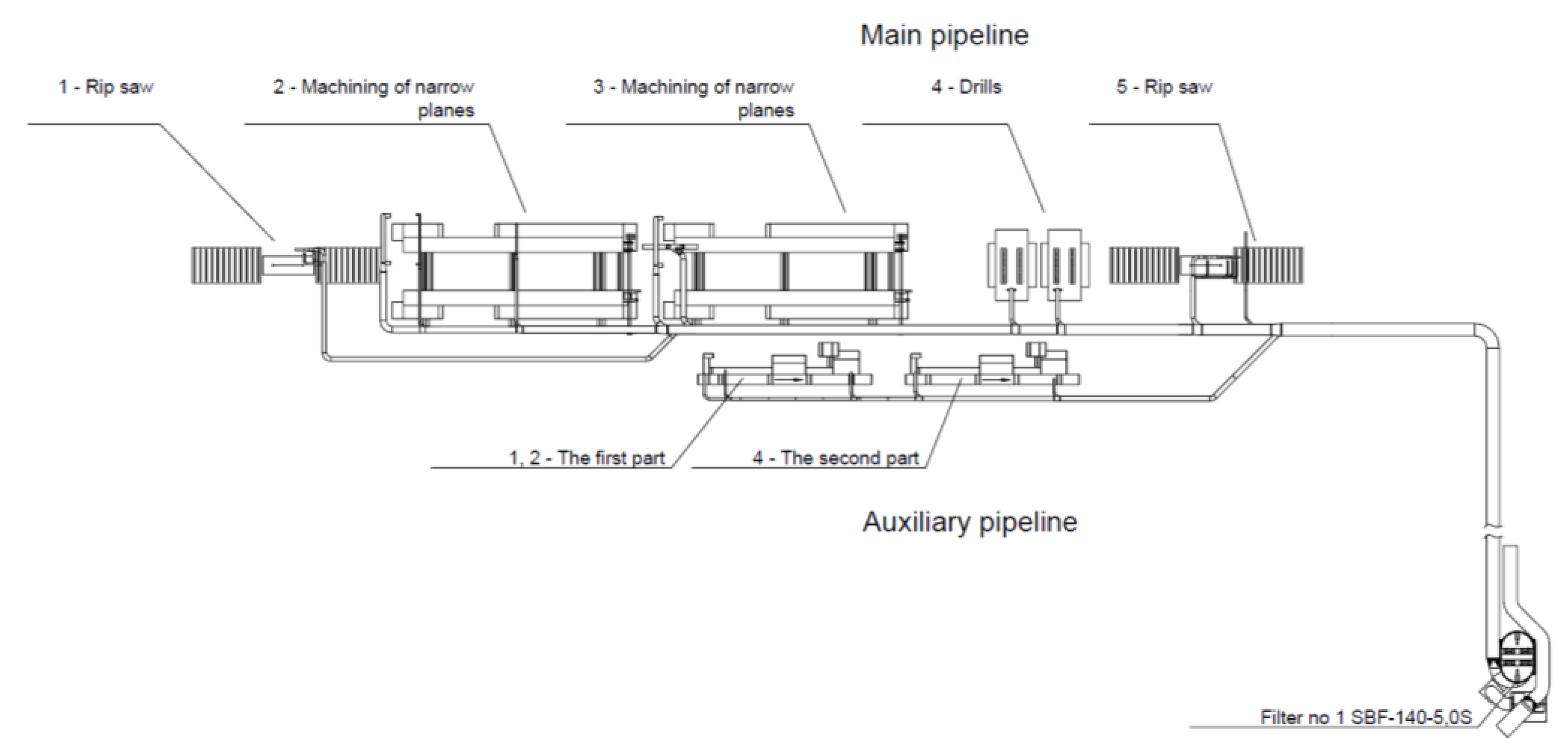
The processing of narrow surfaces is used for formatting and veneering furniture panels with rectilinear shapes. The processing takes place on two lines (main and auxiliary), where the machines performing processing operations related to the formation of fine dust waste are connected to one filtering installation. Chipboard, fibreboard and solid wood are processed on the main line.
The diagram of the line with the dust extraction pipeline is shown in Figure 1.
The stages of processing panels on the main narrow surface processing line are as follows:
  • Longitudinal cutting of the block—a four-element block is cut into two two-element ones, cutting with the use of the FL module (longitudinal saw). Feed 35 m·min−1;
  • Formatting from the width—cutting with a circular saw with the simultaneous alignment of longitudinal, narrow surfaces and veneering. Feed 35 m·min−1;
  • Formatting panels from length and processing short, narrow surfaces. Alignment and veneer. Feed 15 m·min−1;
  • Multi-spindle through-feed drilling machines—drilling holes in wide surfaces of panels;
  • Longitudinal cut—a two-piece block is cut into two ready-made panels. Cutting with a rip saw. Feed 35 m·min−1.
Narrow panels of furniture joints are processed in an auxiliary, one-sided narrow surface processing line. This line is used for processing narrow panels for which the double-sided line is not suitable due to design constraints.
The technological process of furniture panels on this line is as follows:
  • Manual loading of panels.
  • Processing the first narrow longitudinal surface and veneering. Feed 20 m·min−1.
  • Gravity turntable of panels—rotation of the element by 90° around the longitudinal axis.
  • Processing the second narrow longitudinal surface and veneering. Feed 20 m·min−1.
  • Manual unloading and arranging panels.
The dust extraction pipeline operating in the narrow surface processing line is connected to filter No. 1. The estimated amount of generated dust is up to 250 kg·h−1. The line of CNC drilling machines is serviced by a dust extraction pipeline connected to filter No. 2. The estimated amount of waste generated in this line is about 100 kg·h−1. The characteristics of both extraction systems and filter baghouses are presented in Table 1 and Table 2.

CNC Drilling Machines Line

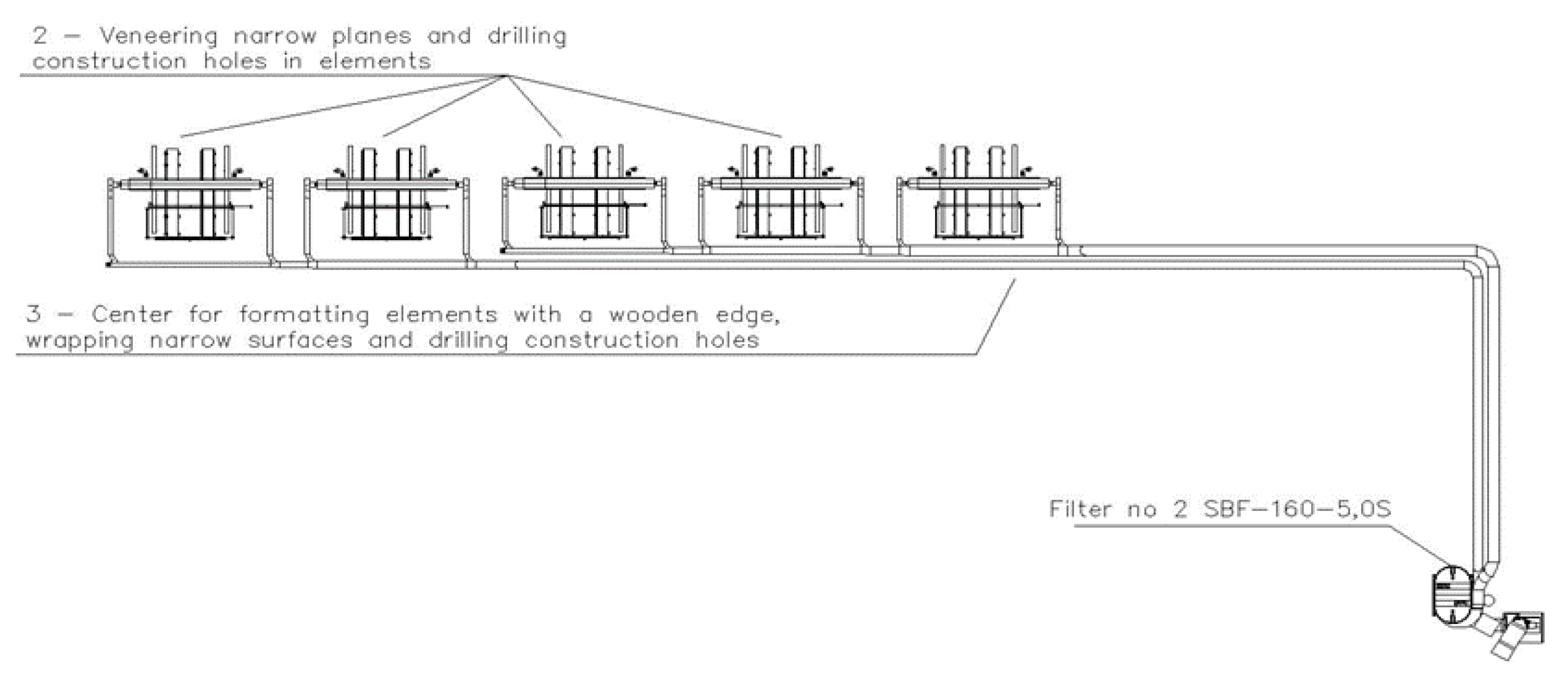
Some types of furniture panel are processed on the line of CNC drilling machines. This is a group of five identical Homag machining and drilling centers with a gantry structure with numerically controlled spindles used mainly as drilling machines for structural holes in the furniture panels. The spindles can also cut curvilinear shapes in furniture panels using cutters. In addition, these machine tools are adapted to veneering narrow surfaces. The line of drilling centers produces dust in the amount of about 100 kg·h−1.
The diagram of the CNC along with the dust extraction system is shown in Figure 2.
The technological process of furniture panels on the line of drilling centers is as follows:
  • Automatic transport and loading—the line consists of five independent machine tools operated by automatic loading and unloading machines.
  • Centers from 1 to 4—taping narrow planes and drilling construction holes in the panels.
  • Center No. 5—formatting panels with a wooden edge, gluing the remaining narrow surfaces and drilling construction holes in the panels.
  • Automatic unloading and transport of panels to the next production stage. On the line of machining centers, formatting tools other than in the line of narrow surface treatment are used. Here, end mills are used instead of saws. The technological similarity of both lines is based on the use of drills. The element that distinguishes this line from the line for processing narrow surfaces of furniture panels is the lack of narrow surface grinders.
On the line of CNC machines, formatting tools other than in the line of narrow surface processing are used. Here, end mills are used instead of saws. The technological similarity of both lines is based on the use of drills. The element that distinguishes this line from the line for processing narrow surfaces of furniture panels is the lack of narrow surface sanding machines.

2.2.2. Dust Extraction Installations and Filter Baghouses

Data on filtration systems and bag filters are provided in Table 1 and Table 2.
Polyester filter bags with a PP (polypropylene) film were used in the tests. The basic properties of the filter medium are presented in Table 3.
After labeling to facilitate further identification, the filter bags were installed in the filter baghouses. After the assumed period of operation, the bags were disassembled and transferred to the laboratory. There, after careful manual removal of the layer of loosely bound dust from the surface, they were shortened to the required length and mounted on the test stand. To ensure the repeatability of the procedure, all bags were stored in separate plastic bags in a separate room, where they were not exposed to any external factors.

2.3. Test Stand

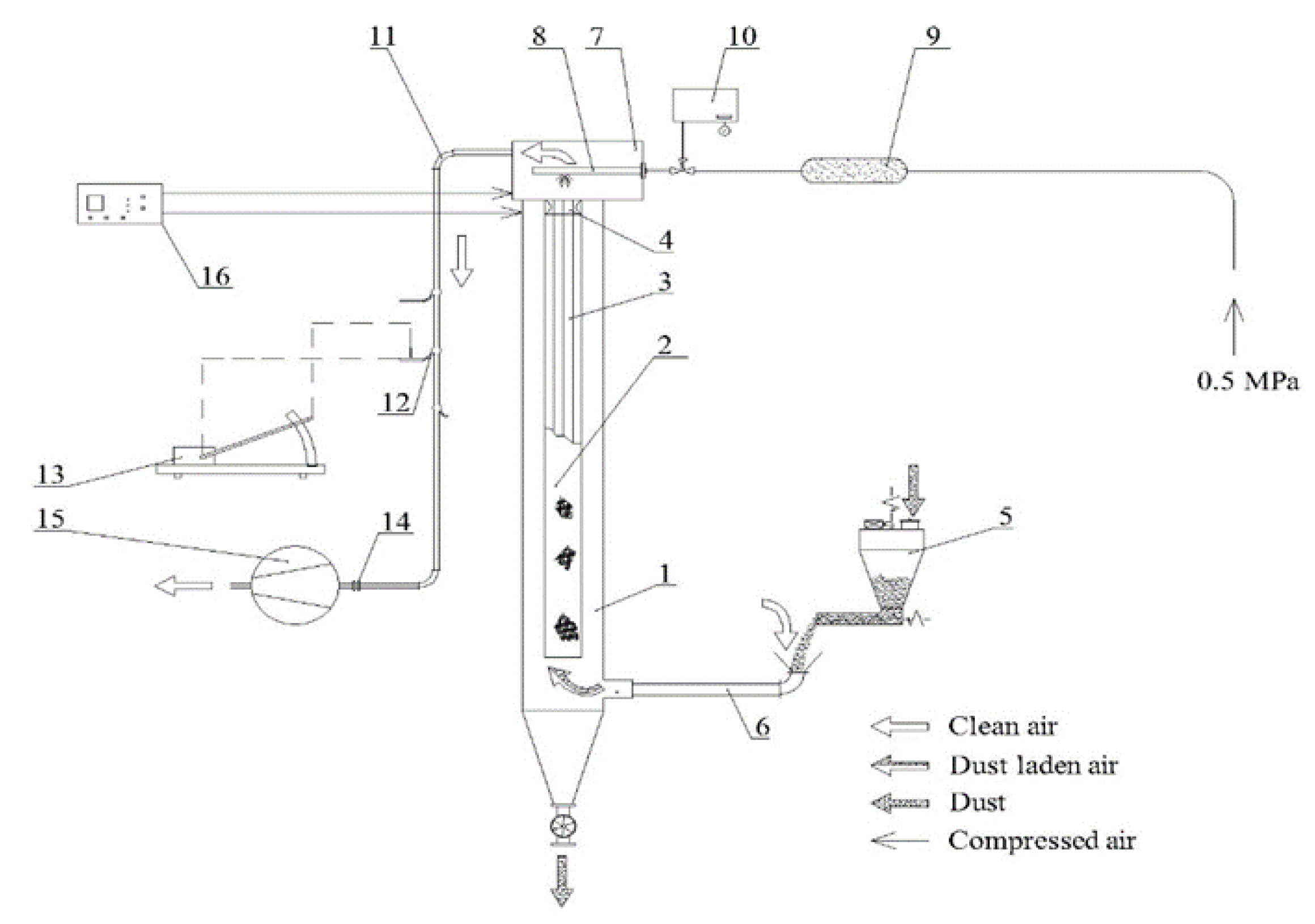
The bags collected at the factory were subjected to measurement procedures using a laboratory stand for testing the filtration process in the pilot-scale (Figure 3). At the stand, it is possible to conduct an experimental filtration process with the use of one bag with a diameter of 150 mm and a working length of 1500 mm. The stand is designed in such a way as to determine the basic operational properties of the bags in conditions similar to the actual conditions of their operation in an industrial filter baghouse. The filtration conditions required during the test are achieved by equipping the stand with appropriate devices, as well as measurement and control systems, such as:
  • dust dosing system in the intended amounts and concentration;
  • regulating valve to regulate the volumetric output of the fan of the main air circulation;
  • a system that controls the frequency of cleaning pulses.
Additionally, the stand is equipped with measuring systems that allow the determination of:
  • air flow resistance;
  • air flow rate in the entire measuring system;
  • the content of dust particles in the dust-free air broken down into individual fractions.
The bags collected at the factory were subjected to two-stage tests on this stand. In the first stage, the pressure drop Δp0 across the clean filter fabric was determined, while in the second stage, the total pressure drop Δpc across the filter was tested. The course of measuring the pressure drop across the clean filter consisted in reading the static pressure difference in the filtration chamber on both sides of the bag with increasing filtration velocity. The data were used to plot the empirical function f: wf → Δp0. Measurement of the total pressure drop consisted in registering the static pressures in the filtration chamber on both sides of the bag immediately before and after each cleaning pulse. This resulted in a maximum and residual pressure drop in each pulse. These tests were carried out with the assumed constant filtration parameters presented in Table 4. Tukey’s test was performed for Δpc at the significance level of 0.05.

2.4. Dust Used in Tests

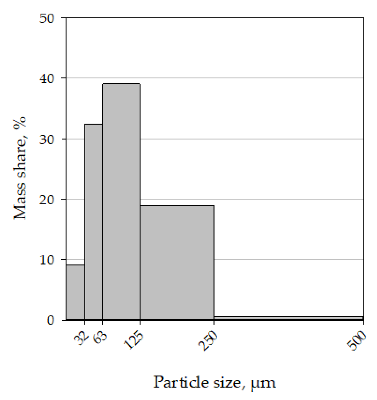
In order to maintain the possibility of comparing the effects of filtration with the use of filter bags operating in different industrial dust collectors, the same dust was used in laboratory tests of all bags. It was fine dust from the sanding of bent beech wood furniture panels. The bulk density of this dust was 177.8 kg·m−3. The particle-size distribution of the dust was also determined by the sieve analysis method (Figure 4). The mass arithmetic mean particle size of 91 μm was determined based on the particle-size distribution. Standard deviation of the distribution was of 39.8 μm.

2.5. Calculations of the K2 Coefficient Value

As a result of the tests carried out by means of a simple calculation from Formula (2), the K0 value was obtained from the measurement of the pressure drop across the clean filter bags. The dust resistance coefficient K2 was also calculated, which depends on the pressure drop Δpp across the dust cake, filtration velocity wf and the dust areal density of the filtering surface s in accordance with Equation (4), after transforming Equation (3):
K 2 = Δ p p w f · s       [ s 1 ] ,
The dust areal density of the surface in the tests was calculated from Formula (5).
s = w f · c · t [ kg · m 2 ] ,
where c is the dust concentration at the test stand inlet 0.01 kg·m−3, and t is the time between cleaning pulses of 300 s.

3. Results and Discussion

Filter bags from two installations operating in the same furniture factory in different technological lines were used for the test. Thus, data were obtained on the characteristics of the formation of air flow resistance through bags made of the same non-woven fabric installed in filters differently loaded with air carrying various types of dust waste.
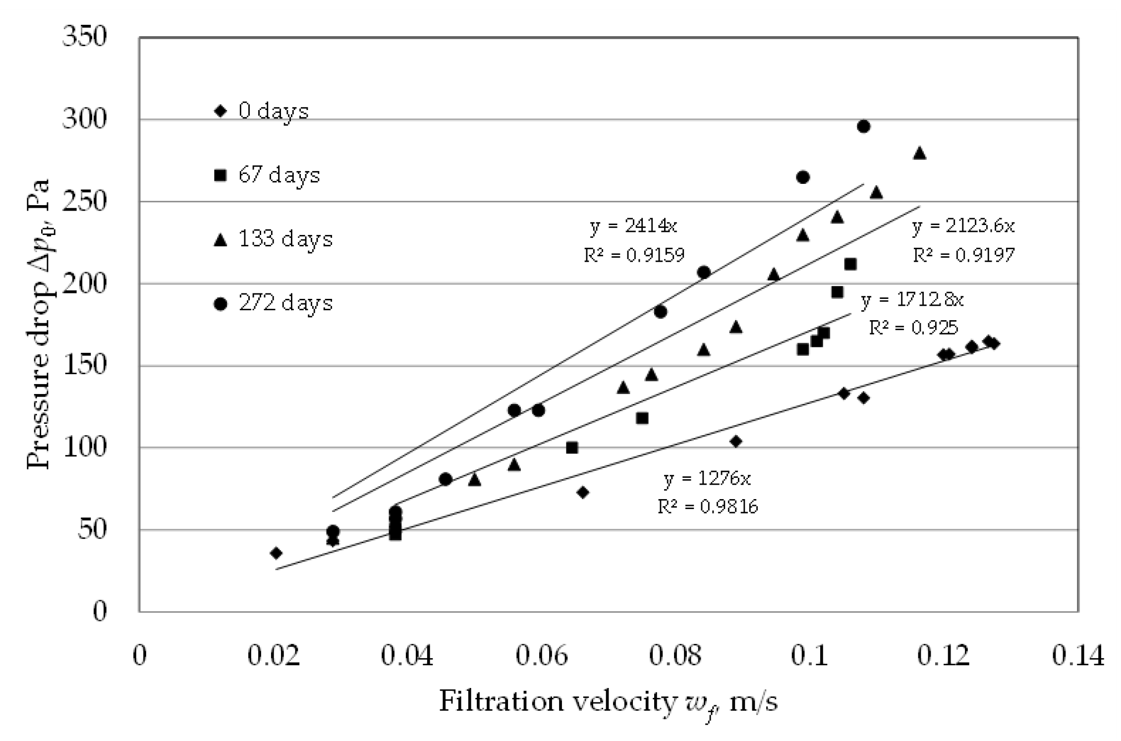
Before testing the total pressure drop Δpc for individual bags, the pressure drop across the bags Δp0 during the clean air flow was determined. This test showed an increase in resistance with increasing bag life in an industrial filter. The pressure drop values for the filter bags from both filter baghouses are shown in Figure 5 and Figure 6. The formation of the pressure drop during the flow of clean air through the filter bags is very similar to the results obtained in previous studies on the use of two-layer filter media for the separation of wood dust [26].
The value of the K0 coefficient equal to 1276 [Pa·s·m−1] was read from plot of the clean bag, which had not been used before, as the value of the proportionality coefficient of the regression equation. On the basis of the results obtained in accordance with the Formula (1), the value of the pressure drop across the clean bag Δp0 was calculated for the assumed filtration velocity of 0.0405 m·s−1. This pressure drop is 51.7 Pa. This value was further used to determine the dust cake resistance coefficient.
The operation time of the bags in an industrial installation increases the resistance of clean air flow through the tested filter fabric. This is certainly due to the presence of dust inside the bag structure that was previously used in an industrial dust collector. Higher resistances were obtained for the bags working in filter 2 in the dust extraction installation of the CNC drilling machine line. The pulse-jet baghouse in this installation works in lighter conditions (filtration velocity and less waste than in the narrow surfaces processing line) and the bags are cleaned less frequently. This shows that the frequency of cleaning pulses has a decisive influence on the air flow resistance.
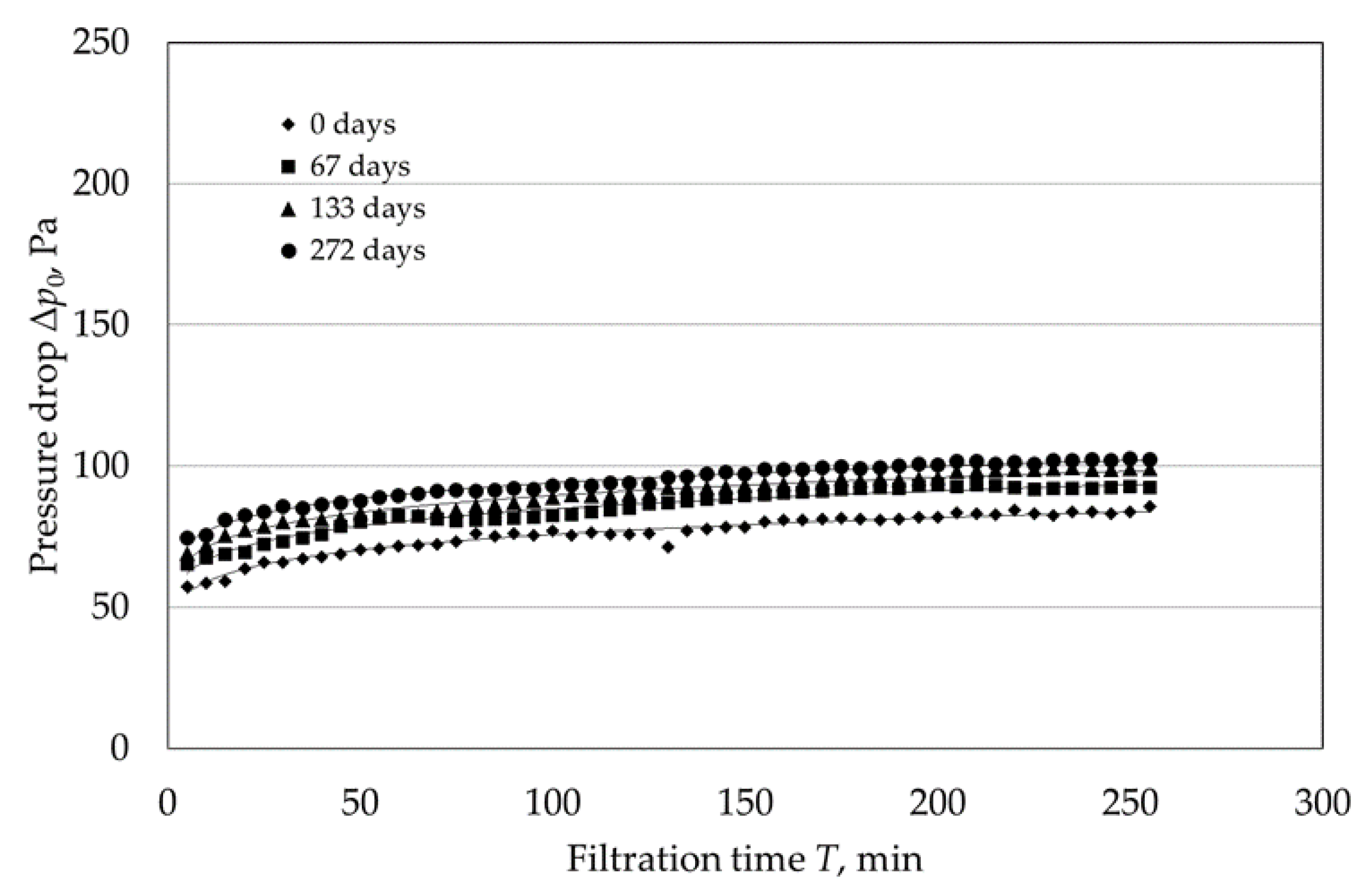
In the second stage of the test, the total pressure drop was measured during the experiments with the use of filter bags previously working in industrial filters for 67, 133 and 272 days and a clean bag, not previously used. The same test wood dust was used in all the experimental air purification processes. Figure 7 and Figure 8 show the maximum pressure drop Δpc in individual filtration cycles for the tested filter bags from baghouses 1 and 2 respectively. Both figures show the pressure drop curves for bags that were used in industrial installations. The course of the increase in total pressure drop during experimental filtration processes is characteristic for this type of filtration process.
In the initial phase, the pressure drop increases quite quickly, but with the time of the experiments, the increase in the pressure drop gets smaller. This proves the stabilization of the dust cake formed on the surface of the filter medium and thus the stabilization of the flow conditions in the entire system.
For bags from both lines it was observed that the longer the fabric was used in the industrial installation, the higher the air flow resistance during laboratory tests. Comparing both lines, it can be concluded that slightly higher resistances were observed for the bags of the CNC drilling machine line. However, in the case of the longest operation life of 272 days, this difference was significant.
Based on the regression equations for pressure drop obtained in individual test filtration processes, the values of the total pressure drop for the 50th filtration cycle were calculated. The equations and values of Δpc are presented in Table 5. The total pressure drop difference of the bags from the filter 1 and from the filter 2 were statistically significant for the 67th day and 272nd day. However, the absolute difference was much greater for the 272nd day.
Using the Δpc value from Table 5, the values of the K2 dust resistance coefficient were calculated based on Formula (4) for all test processes. The results of these calculations are presented in Table 6.
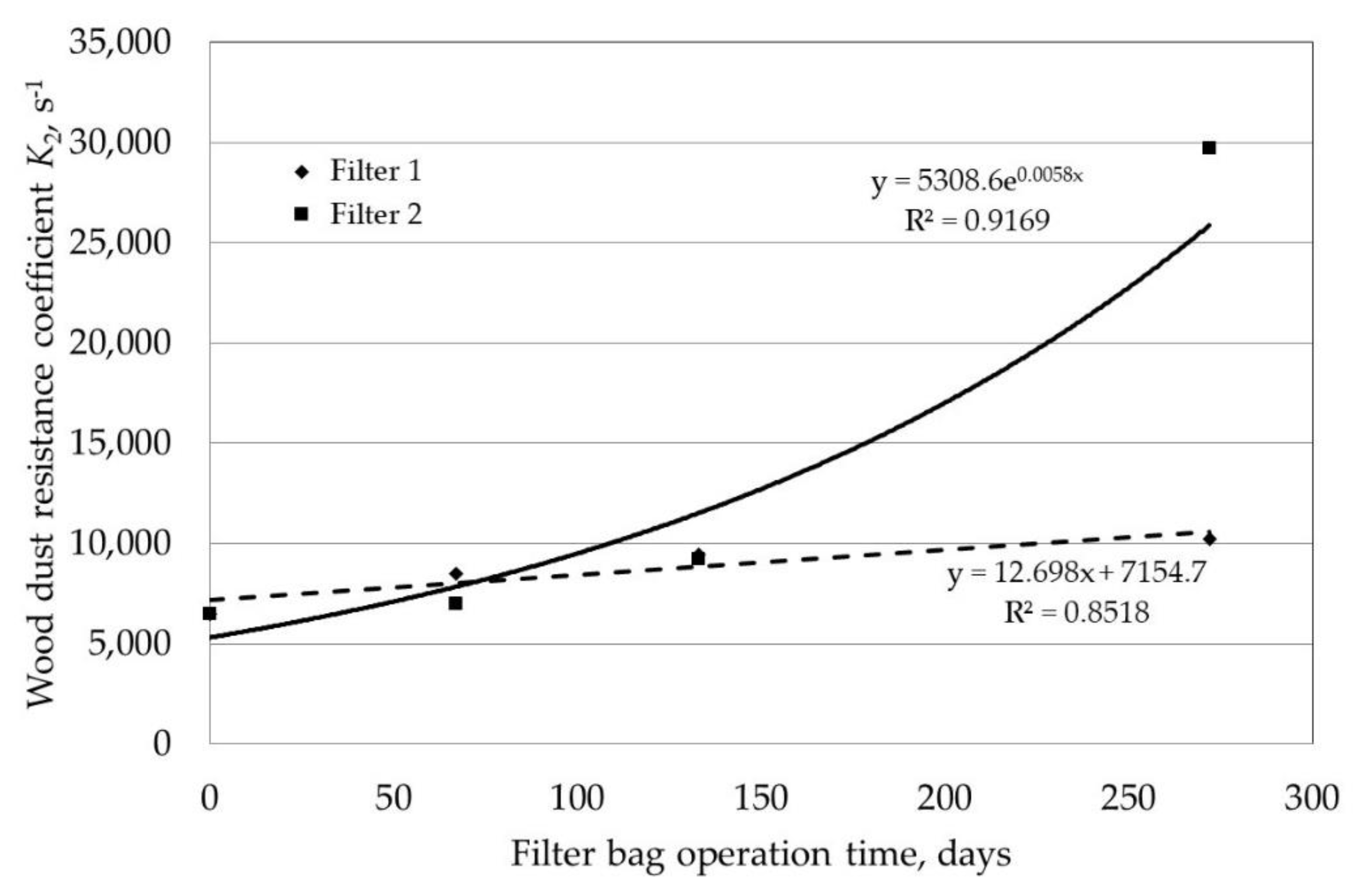
Figure 9 shows the dependence of the K2 coefficient on the operation time of the bags in the installation in both lines.
Based on the results obtained, differences in the value of the K2 coefficient were observed. Extending the operation time of bags in industrial installations increases the K2 coefficient from 6400 s−1 to over 10,100 s−1 in the case of narrow surface processing line (filter 1) to almost 30,000 s−1 in the case of CNC drilling machines line (filter 2). Higher values of the K2 coefficient were obtained for the CNC drilling machine line, in which the bags operating in the industrial installation were less loaded with dust and the dust particles were coarser. The factor that determines the value of the K2 coefficient is the frequency of cleaning pulses. In the filter in the narrow plane processing line, where the frequency of cleaning pulses is higher, lower values of the K2 coefficient were obtained, even though the dust load of these bags in the industrial installation are much heavier. The values of parameters summarizing the working conditions of the bags in industrial installations and the results of the dust resistance coefficient are presented in Table 7.
The results obtained show that cleaning pulses are an important factor determining the work of filter bags. They can eliminate the potentially negative impact on the filtration process of other factors, such as dust load or particle size of dust in polluted air.
Comparing the results obtained with the earlier studies in which the values of the K2 coefficient for beech dust were determined, it can be concluded that in the case of this filter material, the values of the K2 coefficient for beech wood dust are about half that of the values obtained in the study on wood dust filtration [30]. In these tests, however, a filter material with a higher weight was used and the intervals between the cleaning pulses were much smaller. In other works describing the filtration tests, taking into account the determination of the K2 coefficient value, mineral dusts were usually used. Choi [35] calculates the dust resistance coefficient for fly ash with three different values of the geometric mean diameter (dust from: power plant 19.15 µm, fluidized bed combustion 45.68 µm and paint incinerator 37.55 µm). This dust is much finer than wood dust, hence the K2 coefficient values are much higher and range from 120,000 s−1 to over 300,000 s−1. Saleem et al. [25]. Cheng and Tsai [24] dealt with, inter alia, filtering separation of limestone dust. For this type of dust, at a similar filtration velocity, the values of the K2 coefficient are also much higher than for wood dust. Moreover, the study of the filtration of limestone dust and fly ash carried out by Cheng and Tsai [24] showed a directly proportional increase in the K2 coefficient depending on the filtration velocity. Saleem, et al. [25] came to similar conclusions.
The study on the K2 coefficient during the filtration of coal dust was carried out by Li, et al. [28]. In this case, the focus was on the influence of dust humidity on the filtration resistance caused by the dust cake and the K2 coefficient. The test carried out at similar velocities showed that the value of the K2 coefficient reaches up to about 1.3 × 10⁸ and is definitely higher than in the case of filtering wood dust. It is also highly dependent on the moisture content of the dust.
Studies on the K2 coefficient during filtration, as a rule, concerned research based on mineral dusts. In the available publications, one can also find works on organic maize and tapioca dust in comparison to mineral dust in the form of phosphate concentrate [36]. The research concerned the porosity of the dust cake formed on the filter surface. The results obtained clearly indicate that the porosity of the dust cake depends, inter alia, on the particle size (the smaller the particle size, the lower the porosity, and the higher the cake density) and the filtration velocity. Therefore, a directly proportional increase in the K2 coefficient was shown depending on the increase in the density of the dust cake and inversely proportional to its porosity. The effect of increasing the filtration velocity on the value of the K2 coefficient during filtration has also been proven. The values of the K2 coefficient obtained for individual dusts at the filtration velocity of 5 m·s−1 were: 74,000 s−1 for tapioca dust, 16,000 s−1 for corn dust and 23,200 s−1 for phosphate concentrate dust. When analyzing the particle size and dust density, we conclude that these parameters also affect the K2 coefficient. Among the three tested dusts, the density of tapioca and corn and the particle size were similar (density about 1.5 g·cm−1, particle size from 8.5 to 9.5 µm). For the dust from the phosphate concentrate, these values were: density about 3.03 g·cm−3, particle size 15.53 µm. Analyzing the obtained values of the K2 coefficient for individual types of dust, we have come to the conclusion that one of the factors shaping its value is also the dust density. It was found that the dependence of the K2 coefficient value is directly proportional to dust density. Kim et al. (2019) did not study the dust specific resistance coefficient in rice dust in post-harvest processes due to the various particle sizes and low dust concentrations [37].
The presented diagrams (Figure 7 and Figure 8) clearly show the dependence of the filtration resistance on the bag’s working time in the baghouses operated in the dust exhaust installations in the narrow surface processing and the line of CNC drilling machines. The longer the working time of the filter bags, the greater the resistance. This is also confirmed by the diagram of the resistance of clean air flow through the filter and the related value of the K2 coefficient increasing with working time of material. It follows that the operation time (maturation, conditioning) of the filter bags affects the formation and the value of the K2 coefficient. The pulse-jet cleaning intensity is associated with the working time, it turns out that the filter bags cleaned more frequently retaining lower flow resistance despite the greater load of finer dust. The effective pulse-jet cleaning of filter bags is dependent on the specific dust resistance coefficient. The studies performed using limestone dust and fly ash show that the increase of the K2 coefficient requires higher cleaning parameters [38,39].
Long-term operation of the filter bags can be simulated under laboratory conditions. The methods of aging filter materials in laboratory conditions, used so far by Saleem, et al. [20] and Mukhopadhyay and Bawane, (2015) [21] corresponded to the number of cleaning pulses for a period of approximately 100 days of bag work in a furniture factory (maximum 10,000 cycles), while the operation life of such bags is often several years. As a result, such artificial aging of filter bags may turn out to be unreliable; therefore, to verify the actual operation of such bags, they must be tested taking into account their use in real conditions.
4. Conclusions

The research conducted has shown that the properties of filter non-woven fabrics used in industrial conditions change during their operation. It has been shown that the air flow resistance through the filter fabric increases with the longer filtration time. On the basis of the results obtained, it can be concluded that the operation properties of the filter bags depend not only on their primary operating characteristics, but also on their working conditions. The conditions in which the filter bags work also include the high dust load and the low size of the dust particles. These factors negatively affect the filtration resistance, but their influence can be compensated by the increased frequency of cleaning pulses. It has also been shown that the K2 coefficient is influenced not only by the filtration velocity, moisture content of dust, porosity and density of the dust layer, particle size and density of the material from which the dust was produced, but also by the length of the bag operation time.
The high parameters of pulse-jet cleaning pulse frequency and initial pressure should be used to reduce the increase of the pressure drop in bag filters for wood dusts. The value of the dust specific resistance coefficient can be an indicator of the need for this reduction.

Author Contributions

Conceptualization, C.D., S.D. and T.R.; methodology, C.D. and Z.P.; software, C.D.; validation, C.D., Z.P. and T.R.; formal analysis, C.D. and T.R.; investigation, C.D.; resources, C.D.; data curation, C.D. and Z.P.; writing—original draft preparation, C.D. and Z.P.; writing—review and editing, T.R. and R.K.; visualization, C.D. and Z.P.; supervision, S.D. and T.R.; project administration, T.R. and R.K.; funding acquisition, T.R. and R.K. All authors have read and agreed to the published version of the manuscript.

Funding

This publication is the result of the following projects implementation: the research task No. 506.227.02.00 statutory R&D activities of Faculty of Forestry and Wood Technology, Poznań University of Life Sciences and projects by Ministry of Education, Science, Research and Sport of the Slovak Republic VEGA 1/0324/21 and KEGA 026UMB-4/2021.

Institutional Review Board Statement

Not applicable.

Informed Consent Statement

Not applicable.

Data Availability Statement

Not applicable.

Conflicts of Interest

The authors declare no conflict of interest.

References

  1. Siew, S.S.; Martinsen, J.I.; Kjaerheim, K.; Sparén, P.; Tryggvadottir, L.; Weiderpass, E.; Pukkala, E. Occupational Exposure to Wood Dust and Risk of Nasal and Nasopharyngeal Cancer: A Case-control Study among Men in Four Nordic Countries—With an Emphasis on Nasal Adenocarcinoma. Int. J. Cancer 2017, 141, 2430–2436. [Google Scholar] [CrossRef] [Green Version]
  2. Matrat, M.; Radoï, L.; Févotte, J.; Guida, F.; Cénée, S.; Cyr, D.; Sanchez, M.; Menvielle, G.; Schmaus, A.; Marrer, E. Occupational Exposure to Wood Dust and Risk of Lung Cancer: The ICARE Study. Occup. Environ. Med. 2019, 76, 901–907. [Google Scholar] [CrossRef]
  3. Jacobsen, G.; Schaumburg, I.; Sigsgaard, T.; Schlünssen, V. Non-Malignant Respiratory Diseases and Occupational Exposure to Wood Dust. Part II. Dry Wood Industry. Ann. Agric. Environ. Med. 2010, 17, 29–44. [Google Scholar] [PubMed]
  4. Burton, C.; Bradshaw, L.; Agius, R.; Burge, S.; Huggins, V.; Fishwick, D. Medium-Density Fibreboard and Occupational Asthma. A Case Series. Occup. Med. 2011, 61, 357–363. [Google Scholar] [CrossRef] [PubMed] [Green Version]
  5. Bell, H.K.; King, C.M. Allergic Contact Dermatitis from Urea-Formaldehyde Resin in Medium-Density Fibreboard (MDF): CONTACT POINT. Contact Dermat. 2002, 46, 247. [Google Scholar] [CrossRef] [PubMed]
  6. International Agency for Research on Cancer. Arsenic, Metals, Fibres, and Dusts. IARC Monogr. Eval. Carcinog. Risks Hum. 2012, 100, 11–465. [Google Scholar]
  7. Directive (EU) 2017/2398 of the European Parliament and of the Council of 12 December 2017 Amending Directive 2004/37/EC on the Protection of Workers from the Risks Related to Exposure to Carcinogens or Mutagens at Work 2017. Available online: https://www.eumonitor.eu/9353000/1/j9vvik7m1c3gyxp/vklpgng5lezp (accessed on 24 September 2021).
  8. Simon, X.; Bémer, D.; Chazelet, S.; Thomas, D. Downstream Particle Puffs Emitted during Pulse-Jet Cleaning of a Baghouse Wood Dust Collector: Influence of Operating Conditions and Filter Surface Treatment. Powder Technol. 2014, 261, 61–70. [Google Scholar] [CrossRef]
  9. Očkajová, A.; Kučerka, M.; Krišťák, L.; Igaz, R. Granulometric Analysis of Sanding Dust from Selected Wood Species. BioResources 2018, 13, 7481–7495. [Google Scholar] [CrossRef]
  10. Kminiak, R.; Orlowski, K.A.; Dzurenda, L.; Chuchala, D.; Banski, A. Effect of Thermal Treatment of Birch Wood by Saturated Water Vapor on Granulometric Composition of Chips from Sawing and Milling Processes from the Point of View of Its Processing to Composites. Appl. Sci. 2020, 10, 7545. [Google Scholar] [CrossRef]
  11. Kos, A.; Beljo-Lučić, R.; Šega, K.; Rapp, A.O. Influence of Woodworking Machine Cutting Parameters on the Surrounding Air Dustiness. Holz Roh Werkst 2004, 62, 169–176. [Google Scholar] [CrossRef]
  12. Beljo-Lučić, R.; Čavlović, A.O.; Jug, M. Definitions and Relation of Airborne Wood Dust Fractions. In Proceedings of the 4th International Scientific Conference—Woodworking Techniques, Prague, Czech Republic, 7 September 2011; pp. 25–32. [Google Scholar]
  13. Očkajová, A.; Kučerka, M.; Kminiak, R.; Krišťák, Ľ.; Igaz, R.; Réh, R. Occupational Exposure to Dust Produced When Milling Thermally Modified Wood. Int. J. Environ. Res. Public Health 2020, 17, 1478. [Google Scholar] [CrossRef] [Green Version]
  14. Kminiak, R.; Kučerka, M.; Kristak, L.; Reh, R.; Antov, P.; Očkajová, A.; Rogoziński, T.; Pędzik, M. Granulometric Characterization of Wood Dust Emission from CNC Machining of Natural Wood and Medium Density Fiberboard. Forests 2021, 12, 1039. [Google Scholar] [CrossRef]
  15. Pędzik, M.; Rogoziński, T.; Majka, J.; Stuper-Szablewska, K.; Antov, P.; Kristak, L.; Kminiak, R.; Kučerka, M. Fine Dust Creation during Hardwood Machine Sanding. Appl. Sci. 2021, 11, 6602. [Google Scholar] [CrossRef]
  16. Mukhopadhyay, A. Pulse-Jet Filtration: An Effective Way to Control Industrial Pollution Part II: Process Characterization and Evaluation of Filter Media. Text. Prog. 2010, 42, 1–97. [Google Scholar] [CrossRef]
  17. Mukhopadhyay, A. Pulse-Jet Filtration: An Effective Way to Control Industrial Pollution Part I: Theory, Selection and Design of Pulse-Jet Filter. Text. Prog. 2009, 41, 195–315. [Google Scholar] [CrossRef]
  18. Lu, H.-C.; Tsai, C.-J. A Pilot-Scale Study of the Design and Operation Parameters of a Pulse-Jet Baghouse. Aerosol Sci. Technol. 1998, 29, 510–524. [Google Scholar] [CrossRef]
  19. Potok, Z.; Rogoziński, T. Pilot-Scale Study on the Specific Resistance of Beech Wood Dust in a Pulse-Jet Filter. Sustainability 2020, 12, 4816. [Google Scholar] [CrossRef]
  20. Saleem, M.; Khan, R.U.; Tahir, M.S.; Krammer, G. Experimental Study of Cake Formation on Heat Treated and Membrane Coated Needle Felts in a Pilot Scale Pulse Jet Bag Filter Using Optical In-Situ Cake Height Measurement. Powder Technol. 2011, 214, 388–399. [Google Scholar] [CrossRef] [Green Version]
  21. Mukhopadhyay, A.; Bawane, H.S. Emission of Fine Particles and Ageing Behavior of PTFE Finished Filter Media during Industrial Pollution Control. Environ. Pollut. 2015, 4, 58. [Google Scholar] [CrossRef] [Green Version]
  22. Callé, S. Changes in the Performances of Filter Media during Clogging and Cleaning Cycles. Ann. Occup. Hyg. 2001, 45, 115–121. [Google Scholar] [CrossRef]
  23. Koehler, J.L.; David, L. Model Calibration for Pressure Drop in a Pulse-Jet Cleaned Fabric Filter. Atmos. Environ. 1983, 17, 1909–1913. [Google Scholar] [CrossRef]
  24. Cheng, Y.-H.; Tsai, C.-J. Factors Influencing Pressure Drop through a Dust Cake during Filtration. Aerosol Sci. Technol. 1998, 29, 315–328. [Google Scholar] [CrossRef]
  25. Saleem, M.; Krammer, G.; Tahir, M.S. The Effect of Operating Conditions on Resistance Parameters of Filter Media and Limestone Dust Cake for Uniformly Loaded Needle Felts in a Pilot Scale Test Facility at Ambient Conditions. Powder Technol. 2012, 228, 100–107. [Google Scholar] [CrossRef] [Green Version]
  26. Cirqueira, S.S.R.; Tanabe, E.H.; Aguiar, M.L. Evaluation of Operating Conditions during the Pulse Jet Cleaning Filtration Using Different Surface Treated Fibrous Filters. Process Saf. Environ. Prot. 2017, 105, 69–78. [Google Scholar] [CrossRef]
  27. Chen, Y.-S.; Hsiau, S.-S.; Lee, H.-Y.; Chyou, Y.-P. Filtration of Dust Particulates Using a New Filter System with Louvers and Sublouvers. Fuel 2012, 99, 118–128. [Google Scholar] [CrossRef]
  28. Li, J.; Li, S.; Zhou, F. Effect of Moisture Content in Coal Dust on Filtration and Cleaning Performance of Filters. Physicochem. Probl. Miner. Process. 2016, 52, 365–379. [Google Scholar] [CrossRef]
  29. Lupion, M.; Rodriguez-Galan, M.; Alonso-Fariñas, B.; Gutierrez Ortiz, F.J. Investigation into the Parameters of Influence on Dust Cake Porosity in Hot Gas Filtration. Powder Technol. 2014, 264, 592–598. [Google Scholar] [CrossRef]
  30. Rogoziński, T. Pilot-Scale Study on the Influence of Wood Dust Type on Pressure Drop during Filtration in a Pulse-Jet Baghouse. Process Saf. Environ. Prot. 2018, 119, 58–64. [Google Scholar] [CrossRef]
  31. Dolny, S.; Rogozinski, T.; Dobak, S. Methodology of Pilot-Scale Studies on Pulse-Jet Filtration of Air Polluted with Wood Dust. Wood Res. 2019, 64, 325–334. [Google Scholar]
  32. Mao, N.; Yao, Y.; Kanaoka, C. Comparison of Filtration Performances of Cleanable Fabric Filters Measured by VDI and JIS Testing Rigs. Adv. Powder Technol. 2006, 17, 85–97. [Google Scholar] [CrossRef]
  33. Liu, J.X.; Chang, D.Q.; Xie, Y.; Mao, N.; Sun, X. Research on Fine Particles Capture of Baghouse Filter Media. Appl. Mech. Mater. 2013, 300–301, 1293–1297. [Google Scholar] [CrossRef]
  34. Hoeflinger, W. New Developments for Optimal Selection of Filter Media in Fine Dust Bag- House Filtration. Glob. J. Technol. Optim. 2011, 2, 111–116. [Google Scholar]
  35. Choi, J.-H.; Ha, S.-J.; Park, Y.-O. The Effect of Particle Shape on the Pressure Drop across the Dust Cake. Korean J. Chem. Eng. 2002, 19, 711–717. [Google Scholar] [CrossRef]
  36. Ito, L.X.; Aguiar, M.L. A Study of the Porosity of Gas Filtration Cakes. Braz. J. Chem. Eng. 2009, 26, 307–315. [Google Scholar] [CrossRef]
  37. Kim, H.; Kim, O.W.; Lee, H.J.; Ahn, J.H. Dust Collection Performance of Bag Filters in Rice Processing Facilities. Trans. ASABE 2019, 62, 1467–1473. [Google Scholar] [CrossRef]
  38. Tsai, C.-J.; Tsai, M.-L.; Lu, H.-C. Effect of Filtration Velocity and Filtration Pressure Drop on the Bag-Cleaning Performance of a Pulse-Jet Baghouse. Sep. Sci. Technol. 2000, 35, 211–226. [Google Scholar] [CrossRef]
  39. Lu, H.-C.; Tsai, C.-J. Influence of Design and Operation Parameters on Bag-Cleaning Performance of Pulse-Jet Baghouse. J. Environ. Eng. 1999, 125, 583–591. [Google Scholar] [CrossRef]
Figure 1. Scheme of the narrow surface treatment line.
Applsci 11 08965 g001
Figure 2. Line diagram of machining centers.
Applsci 11 08965 g002
Figure 3. Test rig set-up; 1—filtration chamber, 2—filter bag, 3—supporting cage, 4—Venturi tube, 5—dust feeder, 6—dust inlet tube, 7—clean air chamber, 8—tube with cleaning nozzle, 9—compressed air tank, 10—cleaning control device, 11—outlet tube, 12—Prandtl tube, 13—differential manometer for air velocity control, 14—regulation valve, 15—main fan, 16—differential manometer for pressure drop measurements.
Applsci 11 08965 g003
Figure 4. Particle-size distributions of the dust by sieving method.
Applsci 11 08965 g004
Figure 5. Pressure drop across clean filter media from narrow surfaces treatment line.
Applsci 11 08965 g005
Figure 6. Pressure drop across clean filter media from the line of drilling centers.
Applsci 11 08965 g006
Figure 7. Flow resistance Δpc through the filter fabric from narrow surfaces treatment line.
Applsci 11 08965 g007
Figure 8. Flow resistance Δpc through the filter fabric from the line of drilling centers.
Applsci 11 08965 g008
Figure 9. The value of the K2 coefficient depending on the working time of the bags.
Applsci 11 08965 g009
Table 1. Basic technical parameters of filtration installations.
ParameterUnitParameter Value
Dust Extraction Installation in the Processing Line of Narrow SurfacesDust Extraction Installation in the Line of Drilling Centers
Factory installation identification Main pipelineAuxiliary pipelineMain pipelineAuxiliary pipeline
Factory labeling of the filter Filter No. 1—SBF-140-5.0S-1AFilter No. 2—SBF-160-5.0S-1A
Pipeline lengthm144.334.412099
Air velocity in the pipelinem·s−1242.52624
Air demandm3·h−155,45026,60033,250
Fan typeJK-90 MT (1 pcs)
Fan efficiencym3·h−160,000
Table 2. Basic technical parameters of the filter baghouses.
ParameterUnitParameter Value
Filter No. 1—SBF-140-5,0S-1AFilter No. 2—SBF-160-5,0S-1A
Number of bagspcs140162
Bag lengthm4.68
Bag diameterm0.15
The area of the working surface of the bagm22.205
Total working surface area of the bags in the filterm2313.166357.274
Air demand in the installationm3·h−155,45059,850
Filtration velocitycm·s−14.9184.653
The amount of waste generated during processing (wood dust)kg·h−1250100
Average particle sizeµm140.88168.64
Dust loadg·m−34.5091.671
The interval between the regeneration pulses for one bags606690
The number of changes in the work of the bag during the daychanges33
Estimated number of regenerative impulses per daypcs143125
Table 3. Basic technical properties of the filter bags according to the manufacturer.
ParameterUnitParameter Value
Bag producer Gutshe
Fabric type Polyester with PP film
Material weightg·m−2400
Material thicknessmm1.5
Tensile strength—lengthwisedaN·5cm40
Tensile strength—acrossdaN·5cm50
Air permeabilitydm3·min·dm−2250
Surface finishing Thermal stabilization, calendering
High temperature resistance°C90
Acid resistance Good
Alkali resistance Sufficient
Water resistant Weak
Declared filtration efficiency for particles >2.5 µm%99.998
Declared filtration efficiency for particles <2.5 µm%99.957
Table 4. Filtration parameters during testing of filtration non-wovens.
ParameterUnitValue
Air volume flow Vm3·s−10.0286
m3·h−1103.0
Air-to-cloth ratiom3·(m2·h)−1145.8
Filtration velocity wfm·s−10.0405
Inlet dust concentrationg·m−310
Cleaning pulse pressureMPa0.5
Intervals between cleaning pulsess300
Table 5. Summary of regression equations and pressure drop values for the 50th filter cycle. a, b—the same letters in the lines mean no significant differences at the level of significance 0.05.
Line for Processing Narrow SurfacesLine for Drilling Centers
EquationΔpc [Pa]EquationΔpc [Pa]
045.851T0.10983.7 a45.851T0.10983.7 a
6752.186T0.105393.34 b53.218T0.086885.94 a
13356.621T0.099598.08 a73.1T0.051397.04 a
27262.722T0.0879101.91 a160.77T0.0377197.97 b
Table 6. Summary of the resistance values Δpp and the K2 coefficient for individual test variants.
Filter 1 A Line for Processing Narrow SurfacesFilter 2 A Line for Drilling Centers
Δpp [Pa]K2 [s−1]Δpp [Pa]K2 [s−1]
032.0226507.54532.0226507.545
6741.6628466.59634.2626962.76
13346.4029429.86345.3629218.513
27250.23210,208.2146.29229,729.61
Table 7. Working conditions of bags in industrial installations and results of the dust resistance coefficient K2.
Production LineK2 [s−1 ]Intervals between Pulses [s]The Amount of Waste [kg·h−1]Dust Load [kg·(m2min)−1]Average Particle Size [µm]
Line for processing narrow surfaces10,208.26062500.0133140.88
CNC drilling machines line29,729.66901000.0047168.64
Publisher’s Note: MDPI stays neutral with regard to jurisdictional claims in published maps and institutional affiliations.