Article

Concealed Object Detection and Recognition System Based on Millimeter Wave FMCW Radar

Faculty of information Technology, Beijing University of Technology, Beijing 100124, China
*
Authors to whom correspondence should be addressed.
Appl. Sci. 2021, 11(19), 8926; https://doi.org/10.3390/app11198926
Submission received: 2 July 2021 / Revised: 13 September 2021 / Accepted: 23 September 2021 / Published: 24 September 2021
(This article belongs to the Special Issue Applications of Millimeter-Wave and Terahertz Technologies)

Abstract

:
At present, millimeter wave radar imaging technology has become a recognized human security solution in the field. The millimeter wave radar imaging system can be used to detect a concealed object; multiple-input multiple-output radar antennas and synthetic aperture radar techniques are used to obtain the raw data. The analytical Fourier transform algorithm is used for image reconstruction. When imaging a target at 90 mm from radar, which belongs to the near field imaging scene, the image resolution can reach 1.90 mm in X-direction and 1.73 mm in Y-direction. Since the error caused by the distance between radar and target will lead to noise, the original reconstruction image is processed by gamma transform, which eliminates image noise, then the image is enhanced by linearly stretched transform to improve visual recognition, which lays a good foundation for supervised learning. In order to flexibly deploy the machine learning algorithm in various application scenarios, ShuffleNetV2, MobileNetV3 and GhostNet representative of lightweight convolutional neural networks with redefined convolution, branch structure and optimized network layer structure are used to distinguish multi-category SAR images. Through the fusion of squeeze-and-excitation and the selective kernel attention mechanism, more precise features are extracted for classification, the proposed GhostNet_SEResNet56 can realize the best classification accuracy of SAR images within limited resources, which prediction accuracy is 98.18% and the number of parameters is 0.45 M.

1. Introduction

In recent years, terrorist activities have occurred frequently, mostly in crowded public places such as airports, railway stations and subways [1]. At present, there are publicity and security measures to prohibit the carrying of dangerous goods in relevant areas, but the existing security mode cannot meet the demand of real-time security in peak passenger flow [2]. Therefore, it is necessary to carry out non-contact human safety inspection for people who may carry dangerous substances. The current security imaging technology mainly consists of X-ray imaging, infrared imaging, millimeter wave imaging and so on.
Currently, millimeter wave radar is widely used in human vital signs measurement, aerial imaging and non-injury detection by analyzing the amplitude and phase information of the received signal [3]. For near-field imaging systems, the millimeter wave can penetrate all kinds of optical opaque materials and dielectric materials, such as composite materials, ceramics and clothing. It can penetrate the surface to image the hidden target. Millimeter wave radar detection imaging technology has great potential in various application markets, such as ground penetrating radar, non-destructive testing and medical imaging. It has become one of the most important imaging technologies in recent ten years. The millimeter wave radar has the advantages of high resolution and no harm to the human body [4]. However, many millimeter wave imaging studies involve highly complex and expensive customized systems. In 2020, MIMO-ISAR technology was used to reduce scanning time in a near-field millimeter wave imaging system [5]. In 2021, dual-polarization antennas were employed to improve the millimeter wave imaging system [6]. This makes it possible to design low-cost and low-power millimeter wave imagers based on the latest development of frequency modulated continuous wave (FMCW) millimeter wave radar with synthetic aperture radar (SAR) [7] and multiple-input multiple-output (MIMO) [8] radar antennas technology. This paper uses the MIMO-SAR radar to move along a zigzag route: the radar starts at three transmit antennas and four receive antennas and transmits the FMCW signal at each position, receives and stores the radar echo signal at the corresponding transmitting position, which generates an equivalent long antenna aperture—the image’s longitudinal resolution and horizontal resolution is guaranteed.
However, in the previous near-field millimeter wave imaging system, human intervention is needed to check whether the tested person is carrying dangerous goods, which greatly reduces the detection efficiency. In recent years, convolutional neural networks have been used for SAR images classification [9]. There is a lot of redundancy in mainstream convolutional neural networks, which leads to the process of training the model taking up a lot of time and memory space. Lightweight convolutional neural networks, such as predicting facial expressions by ShuffleNetV2 [10], complete autonomous vehicle target detection by MobileNetV3 [11] and remote sensing image classification by GhostNet [12], reduce the amount of network parameters and calculations through redefining convolution, adopting branch structure and optimizing the network layer structure. Compared with traditional neural networks, lightweight CNN reduces the size of the model and increases the speed while maintaining the same level of accuracy. On the basis of the existing lightweight neural network, this paper innovatively introduces the SE (squeeze-and-excitation) and SK (selective kernel) attention mechanism module, the importance of each feature channel is automatically acquired through learning, and then the useful features are promoted according to this importance and the features that are not useful for the current task are suppressed. The system performance is improved, and better classification results are obtained.
Therefore, this paper will implement a two-dimensional millimeter wave imaging system based on the combination of the low-cost millimeter wave radar and the MIMO-SAR technology. The IWR1443 mm wave radar board, mmWave-Devpack, mechanical slide rail and TSW1400 mm wave development board are selected to build the hardware environment. Through HSDC Pro, Uniflash, MATLAB, Python and other software environments, three processes can be implemented: (1) radar Z scanning along X and Y axes and acquiring original data; (2) image reconstruction and preprocessing; (3) image recognition. Finally, the target can be detected and recognized. The process is shown in Figure 1.

2. Materials and Methods

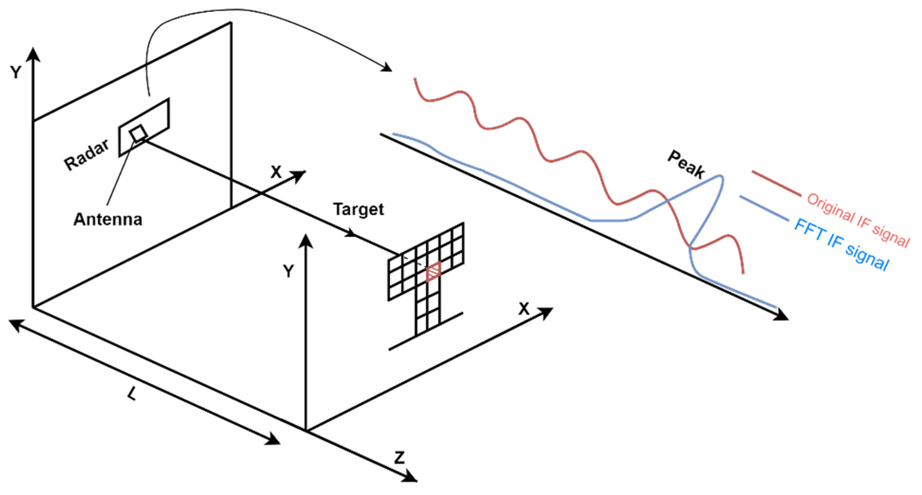
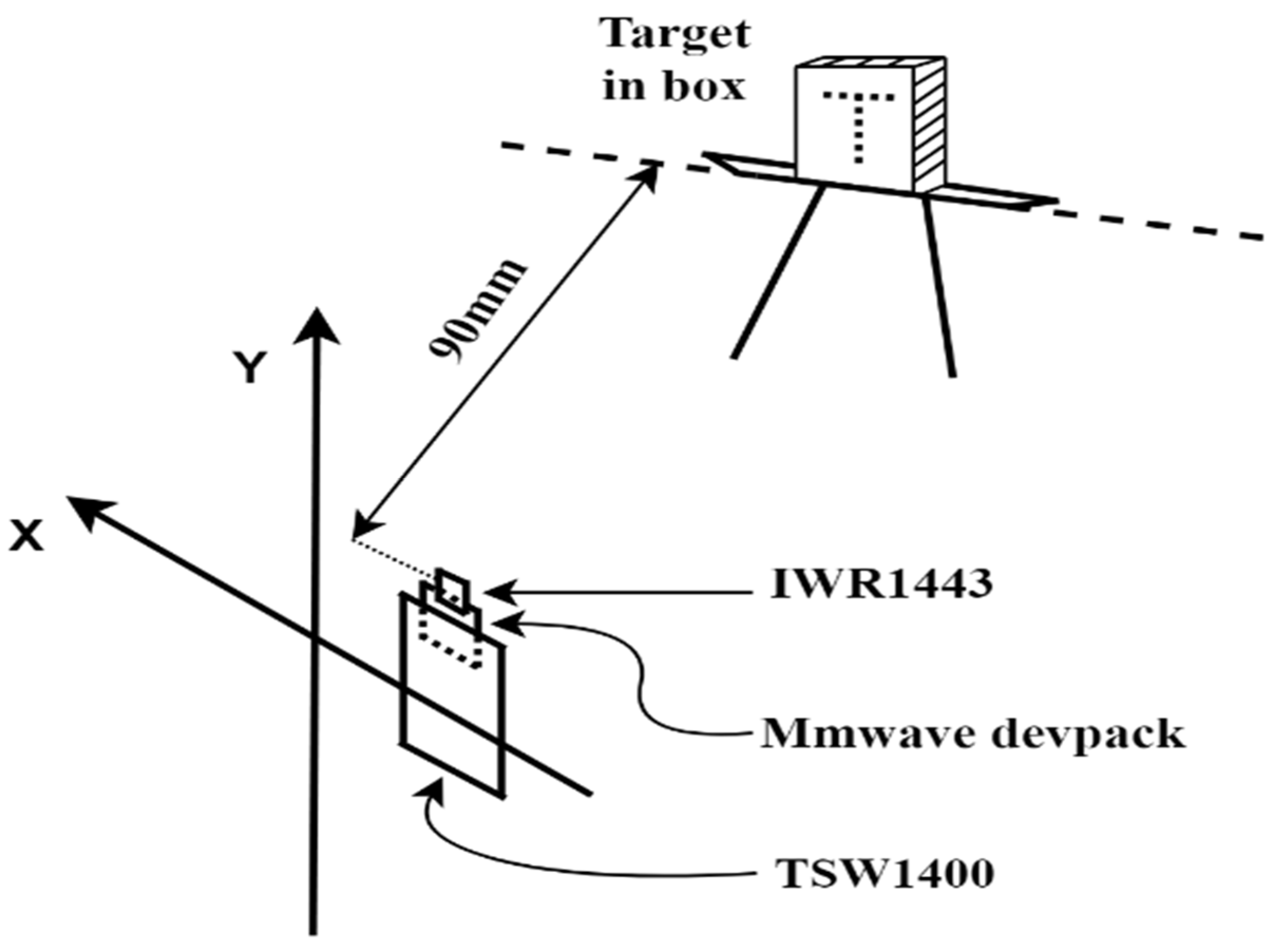
2.1. Test Object Distance

IWR1443 mm wave radar is used in this system to judge whether there is an object in the detection direction. The millimeter wave radar emits continuous frequency modulated waves (FMCW), the obtained intermediate frequency (IF) signal is transformed by fast Fourier transform (FFT), which is analyzed in the frequency domain, then the frequency of the corresponding point at the spectrum peak is obtained [13], as shown in Figure 2.
According to the Formulas (1) and (2), the distance results of metal objects with high reflectivity are shown in Table 1.
f b = k p e a k × f s N F F T
  X = f b × c × T c 2 × B
If the reflectivity of the object is high, the intensity of the IF signal obtained by the radar will be correspondently large. The signal is transformed from the time domain to the frequency domain, where the frequency corresponds to the distance of the object, and the peak value in the frequency domain after the signal transformation indicates that the object exists at the distance.
The two round measurements were measured at different time points. According to the analysis of the experimental results, target distances calculated by the algorithm are consistent with the true values of 0.35 m, 0.50 m and 0.75 m, the relative error is less than 5%. This experiment shows that the existence of a point at a certain distance of an object can be observed statically through the IF signal generated by the radar. This idea is extended to a two-dimensional imaging process, the reflectivity of each point of the target can be obtained by the IF signal.

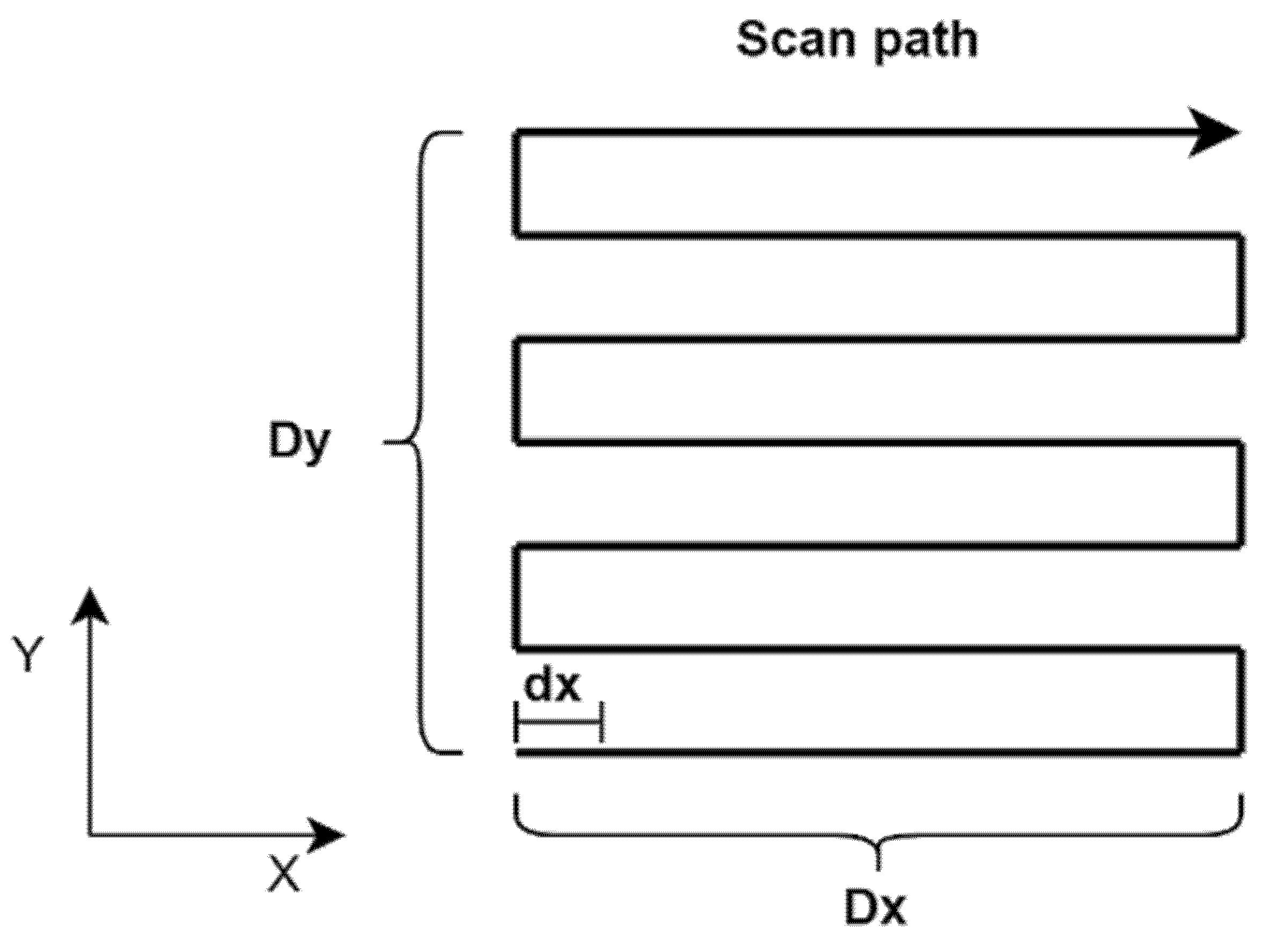
2.2. Synthetic Aperture Radar (SAR) and Multiple-Input Multiple-Output (MIMO) Radar Antennas Technique

Using a single radiation unit, the radar moves continuously along a straight line. After receiving the echo signal of the target at different positions, the intermediate frequency (IF) signal is obtained by radar correlative demodulation and stored; the raw data is then uploaded to the host. In this way, the aperture of the antenna can be increased, which can be regarded as a column of the horizontal antenna array [14]. In the course of a radar Z scan, the MIMO-SAR radar is used to improve image resolution and reduce imaging cost compared to using a multi-radar imaging system. In this paper, GUI in MATLAB is used to control the synchronization of radar transceiver signal and mechanical slide motion. X and Y axis linkage Z scanning as shown in Figure 3.

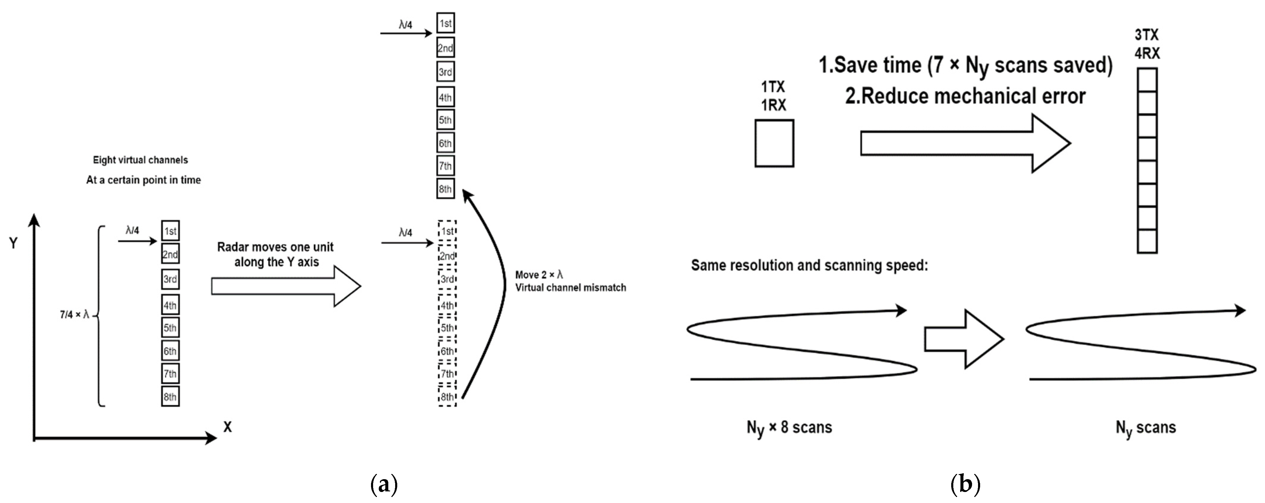
2.2.1. Radar Enabled Three Transmitting Antennas and Four Receiving Antennas

In the first version, the radar uses a single transmitter and single receiver mode, and the sampling interval needs to be controlled at 0.9495 mm in the Y direction, requiring multiple scans, which will increase the error of longitudinal movement of the mechanical slide rail, and it is very time-consuming.
In the second version, in order to ensure the sampling interval and improve the resolution of the image, this paper started with three transmitting antennas and four receiving antennas enabled [15]. Therefore, the concept of the virtual channel can be constructed. A total of 12 virtual channels are arranged linearly in the Y-direction.
In the actual test, it was found that 12 virtual channels are used for data analysis at the same time to generate image blur, which will lead to the decline of resolution. In order to improve the quality of information carried by pixels in the longitudinal direction of the image, this paper removes the virtual channel with a higher interference on the upper edge and lower edge, selecting 8 virtual channels to construct 3D data blocks; the scan length on the Y-axis is estimated to be D y N y ( M 1 ) λ 4 where M = 8 ,   N y is the number of scans in the Y direction. After using the MIMO-SAR radar antennas technology, the mechanical slide moves 2 λ = 7.590   mm each time in the longitudinal direction, the image resolution between each virtual channel is λ / 4 , as shown in the Figure 4a. A comparison of scanning time and equivalent antenna aperture of the single Y-direction scan between the second version and the first version are shown in Figure 4b.

2.2.2. Actual Measurement Parameter Setting

By using the MIMO-SAR radar, the horizontal equivalent antenna aperture is extended when the mechanical slide rail moves at a uniform speed of 20 mm/s. The radar starts with three transmitting antennas and four receiving antennas; 8 virtual channels are used in this paper, and they are arranged linearly; each step in the longitudinal direction is 7.590 mm, and the longitudinal equivalent antenna aperture is extended. The parameters set in this paper can measure the target with a distance of 90 mm from the radar. The number of sampling points in the horizontal direction is 180, and the number of sampling points in the longitudinal direction is 104. Scanning time and image resolution can be well guaranteed. Detailed parameters are shown in Table 2 and Table 3.

2.2.3. Image Resolution

The resolution of reconstructed image depends on wavelength, scan length and target distance. For two-dimensional imaging, the horizontal (X-axis) and longitudinal (Y-axis) resolutions are estimated to be [2,16]:
δ x = λ z 0 2 D x   ,   δ y = λ z 0 2 D y
where D x and D y are the physical lengths of the two-dimensional scan length. According to Z 0 = 90   mm ,   D x = 90   mm ,   D y = 98.67   mm ,   λ = 3.798   mm . The image resolution in X and Y directions are δ x = 1.90   mm and δ y = 1.73   mm .

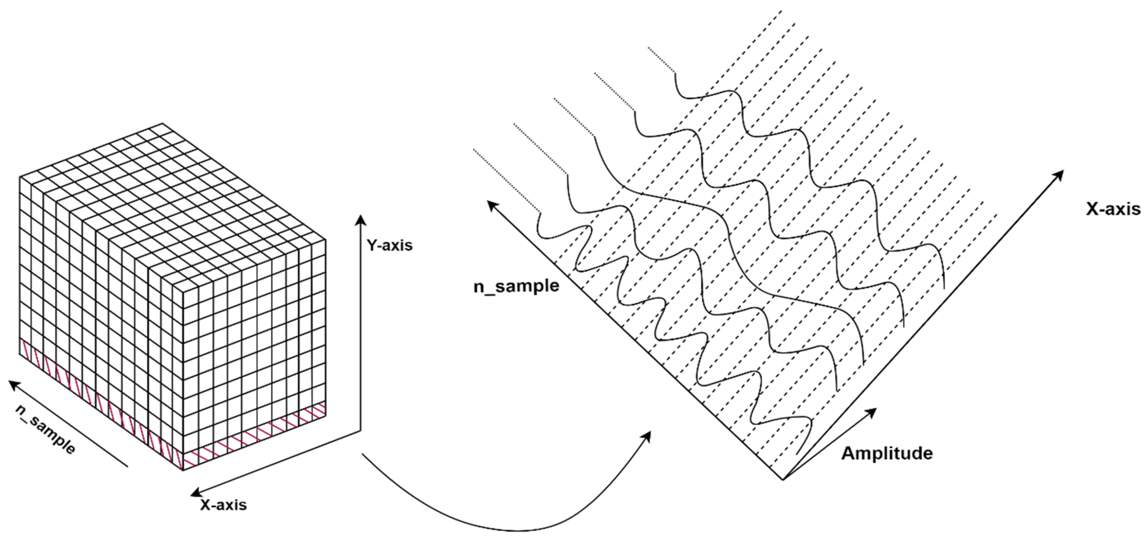
2.2.4. Building 3D Data Block

After analyzing the bin data returned by radar, a one-dimensional array is obtained, which is converted into two-dimensional data blocks according to the number of IF signal sampling points, and then it is converted into a three-dimensional data block according to the number of sampling points in the horizontal direction and longitudinal direction. Each virtual channel is phase compensated [17], and IF signals of the 8 virtual channels are obtained simultaneously, each virtual channel corresponds to a definite longitudinal scale at a definite X-coordinate. Take a 2D data block with a fixed Y-axis value in the 3D data block, as shown in Figure 5.

2.2.5. Reconstruction Image

In the millimeter wave radar imaging process, the radar transmits an FMCW signal and irradiates the target through a synthetic aperture. The received signal at different space points is interferometric demodulated and recorded, and then the IF signal of target to host after scanning is uploaded. Since the purpose of this paper is to generate SAR images, we chose the analytical Fourier transform, which is an existing image reconstruction algorithm [18], according to the dispersion relation of the plane wave in free space, the wave number k is divided into three components in a Cartesian coordinate system:
k x 2 + k y 2 + k z 2 = ( 2 k ) 2
The values of the Fourier transform variables k x and k y are 2 k to 2 k , which satisfy the visible region:
k x 2 + k y 2 ( 2 k ) 2
Two-dimensional plane reflectance of target at a distance of z 0 from the radar can be expressed as:
p ( x , y , z 0 ) = F T 2 D 1 [ n = 0 n s a m p l e 1 [ F T 2 D [ u ( x , y , n ) ] e j k z z 0 ] ]
where u ( x , y , n ) is a three-dimensional data block. F T 2 D and F T 2 D 1 in Formula (6) denote 2D Fourier and inverse Fourier transform operations, respectively.
The following is the image reconstruction of the actual object, as shown in Figure 6. In this paper, the millimeter wave radar is used to detect hidden objects, so the target is placed in a cardboard box with a distance of 90 mm from the radar. The simultaneous activation of the MIMO-SAR radar and the mechanical slide ensured the resolution of the image.
The target used in the test is the scissors, which are opened and placed in the paper box. After the image reconstruction algorithm, the details of the scissors can be clearly seen with high object identification. The result of image reconstruction is shown in Figure 7.
The scissors placed in the paper box can be detected by the millimeter wave radar, and the SAR image is clearly visible, which verifies the effectiveness and reliability of the analytic Fourier imaging algorithm.

2.3. Image Preprocessing

The data set consists of 250 SAR images, which contains 10 categories such as wrench, wire stripper, hammer, rasp, ax, scissors, key, disc, pliers and gun, and each category contains 25 SAR images. The photo of the test object and the corresponding SAR radar image are shown in Figure 8. The experimental setting is to place the item in the carton, and the effect is the same as that when the clothing covers the object.
In the reconstruction algorithm, the distance parameter   Z 0 is given in advance, so that the target can be imaged near this range. The radar original reconstruction image may contain noise, which is caused by the distance error between the target and the radar. In the actual security check process, the relative distance between the object and the radar cannot be guaranteed to be very accurate, so the image preprocessing is very important, which can eliminate noise and enhance the image features and also, improve visual recognition. The radar original reconstructionimage is first processed using the gamma transform algorithm and then linear stretching is carried out, as shown in Figure 9.
s = c r γ
where c = 1 and γ = 2.4 , gamma transform algorithm deals with the normalized brightness and then reverse-transforms to the real pixel gray value. The linear stretch piecewise function is:
f ( x ) = { 0                                                   ,               x < 30 2 x                                                 ,     30 x < 60 120 + ( 235 120 ) ( 215 60 ) ( x 60 ) ,     60 x < 215 235                                             ,               x 215
The gray value of each pixel in image represents the energy of a certain point of the target at a certain distance, so the radar original reconstruction image indicates that the SAR image has the characteristic that the reflected energy of the target is higher than the noise energy. Since the energy value containing the object information is concentrated in the bright region, the gamma transformation algorithm is used, the parameter is adjusted to 2.4 to increase the contrast in the bright areas and decrease the contrast in the dark areas [19]. Then the pixel gray value is handled by a linear stretching algorithm, which contains four piecewise functions: (1) eliminate the noise; (2) preserve the information of the low gray pixel area; (3) map the original pixel value to a higher and wider brightness region, which increases the contrast and brightness of the image; (4) make the image not appear in extremely bright pixels, which ensures the integrity of the image.
By using the gamma transformation algorithm, the effective information of radar original reconstruction image is retained, while the noise is reduced. After the linear stretch, the image is enhanced, and improves the visual recognition. Image preprocessing lays a foundation for the subsequent supervised learning. The results are shown in Figure 10.

2.4. SAR Image Recognition Algorithm

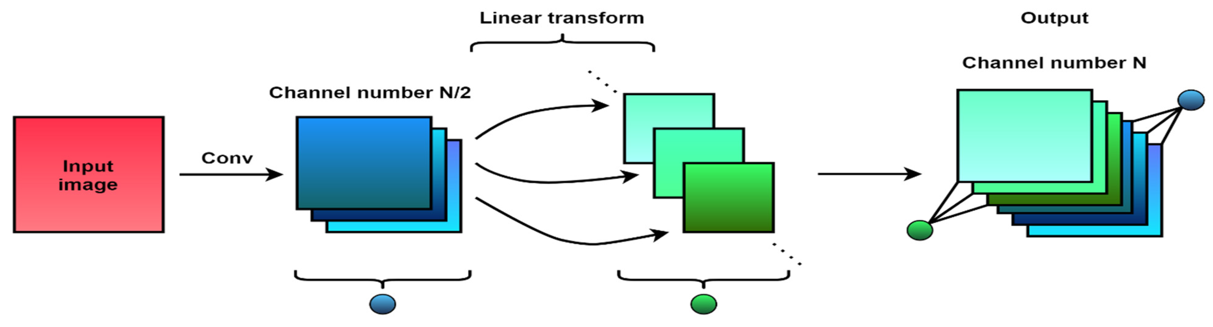
2.4.1. Lightweight Convolutional Neural Networks
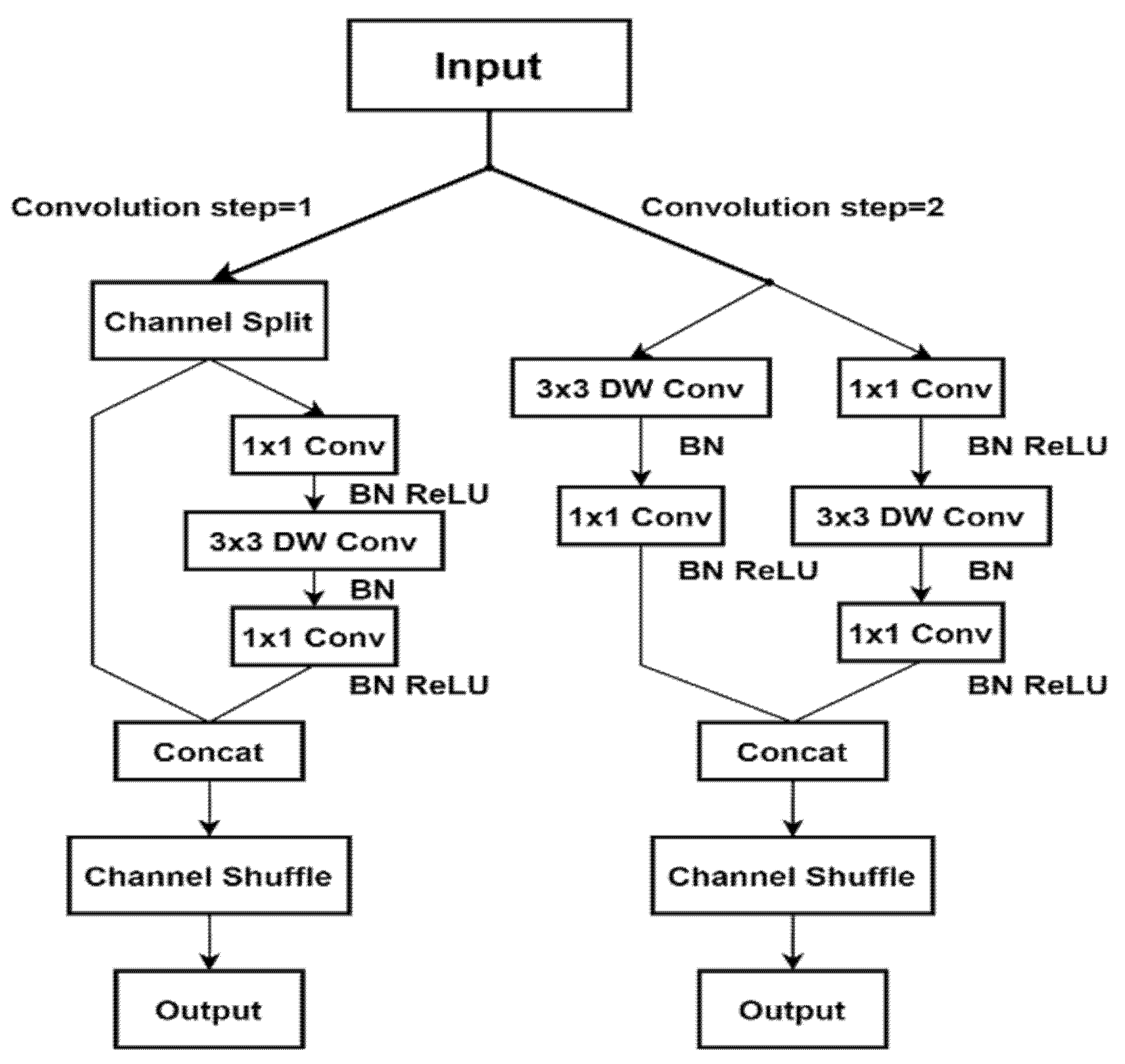
While the traditional convolutional neural network leads to the process of training the model, which occupies a lot of time and memory space, a lightweight convolutional neural network, with the advantages of small model volume, high accuracy and less computation, can be used to construct an object recognition algorithm. Software can be integrated into resource-limited embedded and mobile devices, which meets the actual needs of security scene.
Lightweight convolution neural networks include MobileNet, ShuffleNet, GhostNet and other lightweight models. MobileNet and ShuffleNet, respectively, use point-wise convolution and channel shuffle to achieve the purpose of feature communication, which realizes the fusion of features between different groups. GhostNet adopts a different approach, which is based on a group of original feature images and uses linear transformation to obtain more features that can excavate the useful information from the original features. The original feature and the linear transform feature are spliced together to enlarge the feature image. By redefining the convolution rules, the lightweight model can extract image features efficiently with a shallow network structure and a few parameters.
The active millimeter wave imaging system can obtain single-channel images, which contain less information than light images, and the contrast between target contour and background is not obvious. More importantly, active millimeter wave images will have varying degrees of virtual shadows due to their imaging principle, which will have a great impact on the classification effect. Based on these characteristics, this paper will use the convolution neural network module with the method of experiment and attention mechanism. On the one hand, the convolutional neural network has strong feature extraction ability; on the other hand, the attention mechanism is used to obtain more details of the target to be concerned, so as to suppress interference information in millimeter wave images and improve the efficiency and accuracy of feature extraction.
The data set consists of 250 SAR images in 10 categories, and the training set and the validation set are divided in a ratio of 3 to 2, all of which are scanned at a distance of 90 mm from the radar. Three representative lightweight networks are proposed in this paper: (1) ShufflenetV2; (2) MobileNetV3; (3) GhostNet_ResNet56 based on GhostNet, which have been repeated for five rounds of verification, and the prediction accuracy is the average of the five rounds of experiments. The images are firstly normalized, and the number of image channels input to the neural network is adjusted to adapt to the characteristics of the grayscale images. During the training, the learning rate of all networks is set as 0.01, the batch size is 16, and the epochs are 30.
  • ShuffleNetV2
The ShuffleNetV2 network improves the ShuffleNetV1 network. Firstly, the convolution step size is selected. For the bottleneck block with convolution step size of 1, the input features are first divided into two parts according to channels. The result is entered into two branches, one of which does not take any action to reduce the number of parameters and computational complexity, and the other branch does not take grouping convolution to reduce the memory access cost. For the subsampling building block with convolution step size of 2, the number of feature channels is doubled. In ShufflenetV2, a layer of 1 1 convolution is added before the average pooling layer, to further mix features. Concat module is used to replace the original addition of each element to reduce the computational complexity, and Channel Shuffle module is added to increase the information communication between channels [20]. The ShuffleNetV2 convolutional neural network flowchart is shown in Figure 11.
The SAR images are recognized through ShuffleNetV2 network, and the accuracy of validation set is 84.55%. This low accuracy may be due to the slower convergence speed of the network in a limited number of epochs. Moreover, as the number of epochs increases, the accuracy will be improved to a certain extent.
  • MobileNetV3
MobileNetV3 combines the advantages of MobileNetV1 and MobileNetV2. At the convolution level, MobileNetV1 introduces the deep separable convolution, decomposes the standard convolution into deep convolution and point-by-point convolution, and MobileNetV2 introduces the linear bottleneck and backward residual structure in the network structure. On this basis, MobileNetV3 introduces a squeeze-excitation (SE) attention mechanism in the bottleneck structure. The SE module automatically obtains the importance degree of each feature channel through learning, which enhances the useful features according to the importance degree and inhibits the features that are less useful to the current task [21].
The SAR images are recognized through MobileNetV3 (SE) network, and the accuracy of validation set is 98.18%.
  • GhostNet
GhostNet proposes a novel Ghost module that replaces ordinary convolution and can generate more feature images with fewer parameters. Unlike ordinary convolution, the Ghost module contains two steps. In the first step, the feature image of input is convolved to obtain the feature image with half the channel number of ordinary convolution operation. In the second step, linear transformation is used to obtain another part of the feature image generated in the first step. Finally, the two groups of feature images are stitched together to generate the final feature image. The ghost module can replace the ordinary convolution to reduce the computational cost of the convolution layer [22]. The GhostNet convolutional neural network flowchart is shown in Figure 12.
The SAR images are recognized through the GhostNet_ResNet56 network, and the accuracy of the validation set is 95.45%. This accuracy is significantly higher than that of ShuffleNetv2 but a bit lower than that of MobileNetV3. However, in terms of model parameters and memory usage, GhostNet_ResNet56 is better than MobileNetV3. Thus, GhostNet_ResNet56 is suitable for the classification task of millimeter wave images.
In order to further improve the accuracy of networks, a confusion matrix is used to reflect the accuracy of image classification more clearly, as shown in Figure 13.
It can be seen from the confusion matrix that the GhostNet_ResNet56 network is not good at distinguishing between key, pliers, knife, ax, etc., which leads to lower prediction accuracy. Based on the above three basic network models, it can be seen that the MobileNetV3 convolutional neural network with the introduction of the SE attention mechanism model has the highest prediction accuracy. Therefore, the squeeze-and-excitation (SE) and selective-kernel (SK) attention mechanism modules are used to improve the existing classification network.

2.4.2. Two Optimization Algorithms of Attention Mechanism
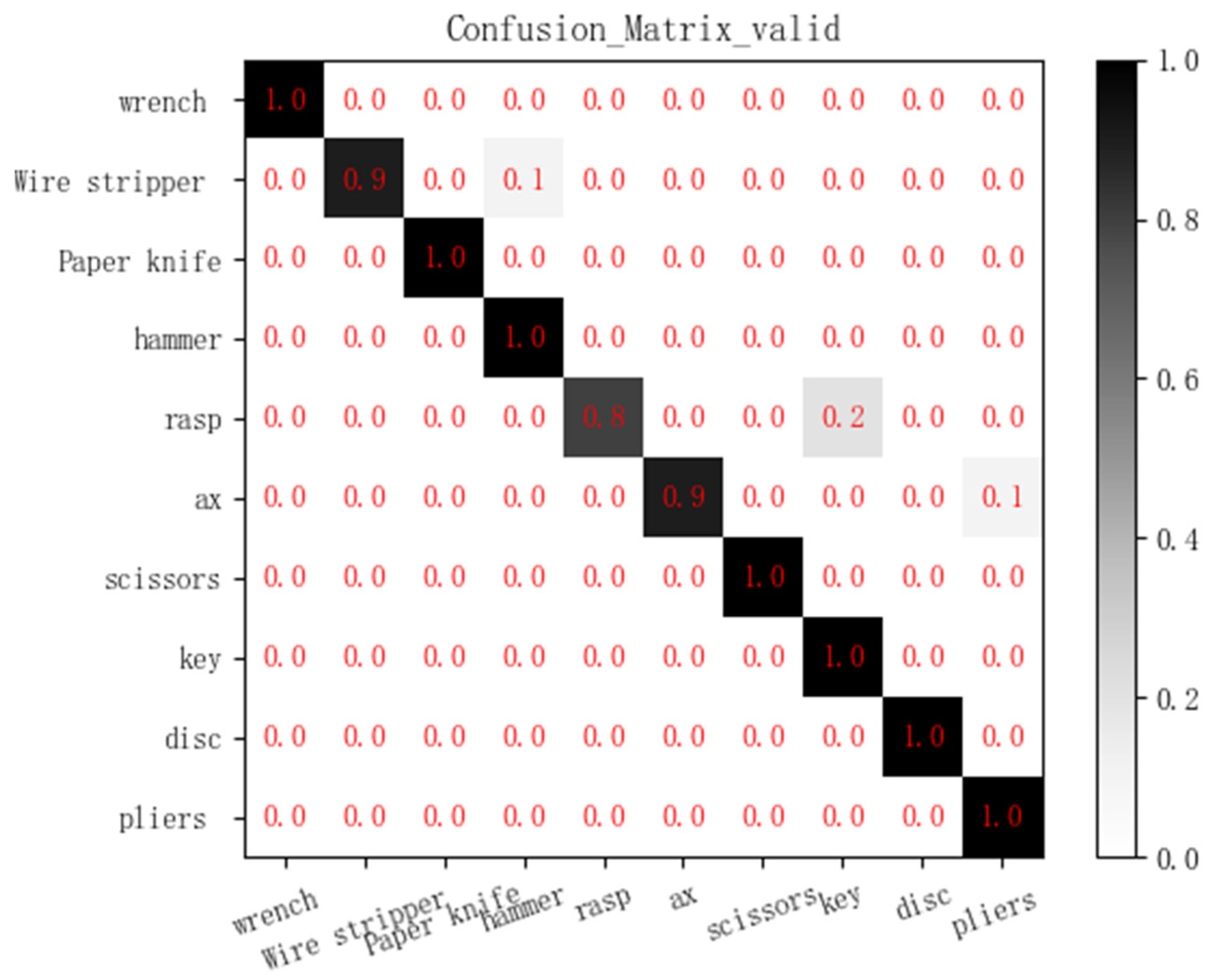
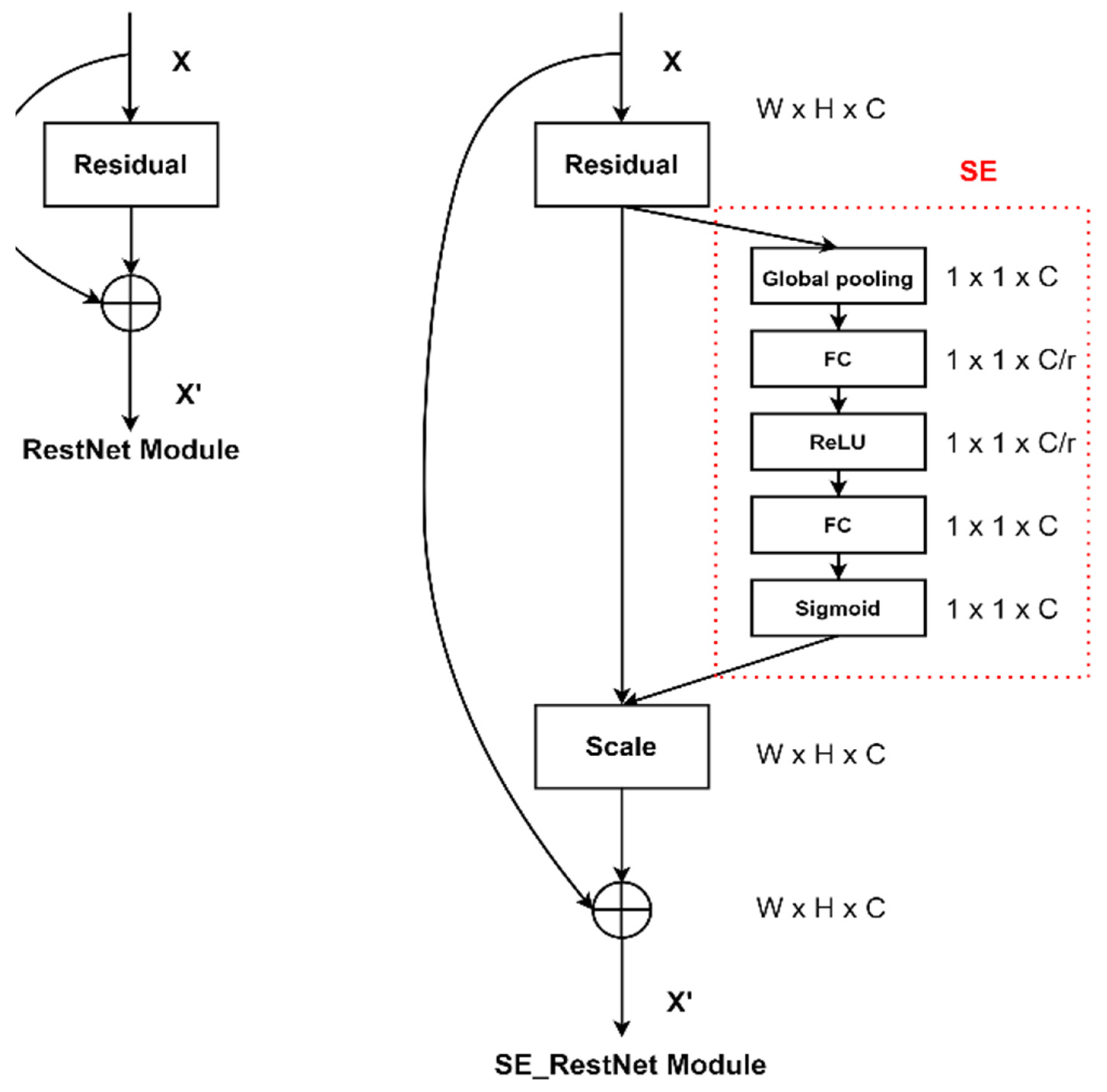
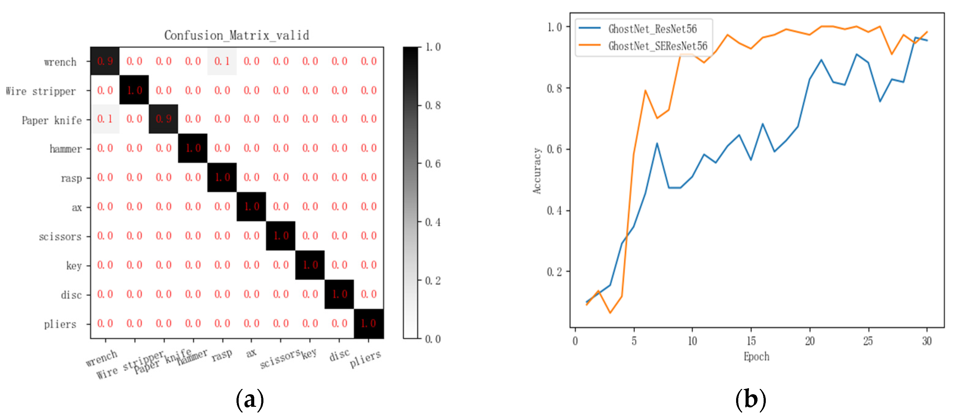
The squeeze-and-excitation (SE) attention mechanism mainly uses squeeze, excitation and scale to recalibrate the previous features. The squeeze operation, which compresses features along the spatial dimension, turns each two-dimensional feature channel into a real number, which has a global receptive field and represents the global distribution of the response over the characteristic channel. The output dimension matches the number of feature channels input. Next is the excitation operations; it is a mechanism similar to the doors for a recurring neural network. The parameter w is used to generate weights for each feature channel. Finally, through scale operation, the weight of the output is treated as the importance of each feature channel after the feature selection and weighted to the previous features to complete the recalibration of the original features in the channel dimension [23].
The selective-kernel (SK) attention mechanism uses a non-linear approach that fuses features from different kernels to adjust the size of the receptive field, which contains split, fuse and select. Split operation generates multiple channels with different kernel sizes, which are related to different receptive field sizes of neurons. The fuse operation combines information from multiple channels to obtain a global and understandable representation for weight selection. The select operation fuses the feature images of different kernel sizes according to the selected weights [24]. In this paper, SE and SK attention mechanisms are used to optimize the neural network algorithms of ShuffleNet series, MobileNet series and GhostNet series.
  • GhostNet_SEResNet56
The squeeze-and-excitation (SE) attention mechanism is introduced into GhostNet_SEResNet56 lightweight convolutional neural network to optimize its network structure [25]. The process is shown in Figure 14.

3. Results and Discussion

According to the results of the confusion matrix, this paper uses SE and SK attention mechanism to optimize MobileNetV3, ShuffleNetV2 and GhostNet lightweight convolutional neural networks. The results are shown in Table 4.
Where Madd represents the number of operations multiplied first and then added, FLOPs represent the number of floating point operations and MemR + W represents the total memory space occupied by the model.
Table 4 shows that the prediction accuracy of the three series networks was significantly improved after the optimization of SE and SK attention mechanism. Although the introduction of the attention module into the SAR image recognition algorithm will increase the network load slightly, it is a tolerable range.
The Madd, Parameters, FLOPs and MemR + W of ShuffleNet series are all higher than those of the other two models, which indicates that the number of calculation amount of the model is the largest and occupies the most memory space, but its prediction performance on SAR image datasets is worse than that of MobileNetV3 series and GhostNet series.
By comparing GhostNet_SEResNet56 and MobileNetV3_SK, the prediction accuracy of GhostNet_SEResNet56 is the same as MobileNetV3_SK; the Madd and FLOPs of GhostNet_SEResNet56 are slightly higher than MobileNetV3_SK, but parameters and MemR + W are significantly lower than MobileNetV3_SK, indicating that GhostNet_SEResNet56 optimized by SE attention mechanism can play the greatest advantages within the most limited resources. The confusion matrix of GhostNet_SEResNet56 algorithm is shown in Figure 15a.
GhostNet_ResNet56 is optimized by the SE attention mechanism. Compared with the network without attention mechanism, the network with attention mechanism can significantly improve the accuracy in few epochs. In addition, its convergence speed is significantly accelerated, and the oscillation effect of the tail is effectively weakened, as shown in Figure 15b. Comprehensively consider the classification accuracy of the neural network and its memory occupation, GhostNet_SEResNet56 are used as the object recognition network in this paper.
In this paper, the millimeter wave imaging system can obtain the target SAR image at 90 mm. The number of virtual channels can be increased by increasing the antenna array, and then the longitudinal antenna aperture can be increased. The horizontal synthetic aperture can be widened by increasing the horizontal slide movement distance. The improved hardware can amplify the measured distance while maintaining the image resolution.
In a realistic scenario, target containers and humans carrying targets can sway and move by more than the wavelength which will cause the image to blur. To solve this problem, the speed of the object can be measured first when the object is moving, and then the influence of the speed can be compensated in the imaging algorithm.
Lightweight neural network of deep learning is used for target recognition. Different from the previous manual intervention mode, dangerous objects are identified by machine learning, which can greatly improve the efficiency of security inspection and reduce the uncertainty of manual identification. The limitation of the system at the present stage of this paper is that only ten categories of objects can be identified, which does not include all dangerous goods. In addition, the accuracy of network prediction after the optimization of SE and SK attention mechanism has not been greatly improved, and the lightweight convolutional neural network is easy to overfit and fall into local optimal solution, so the data set needs to be expanded.

4. Conclusions

In this paper, a detection and recognition system for concealed objects based on the MIMO-SAR radar is proposed. The contributions made in this paper are as follows:
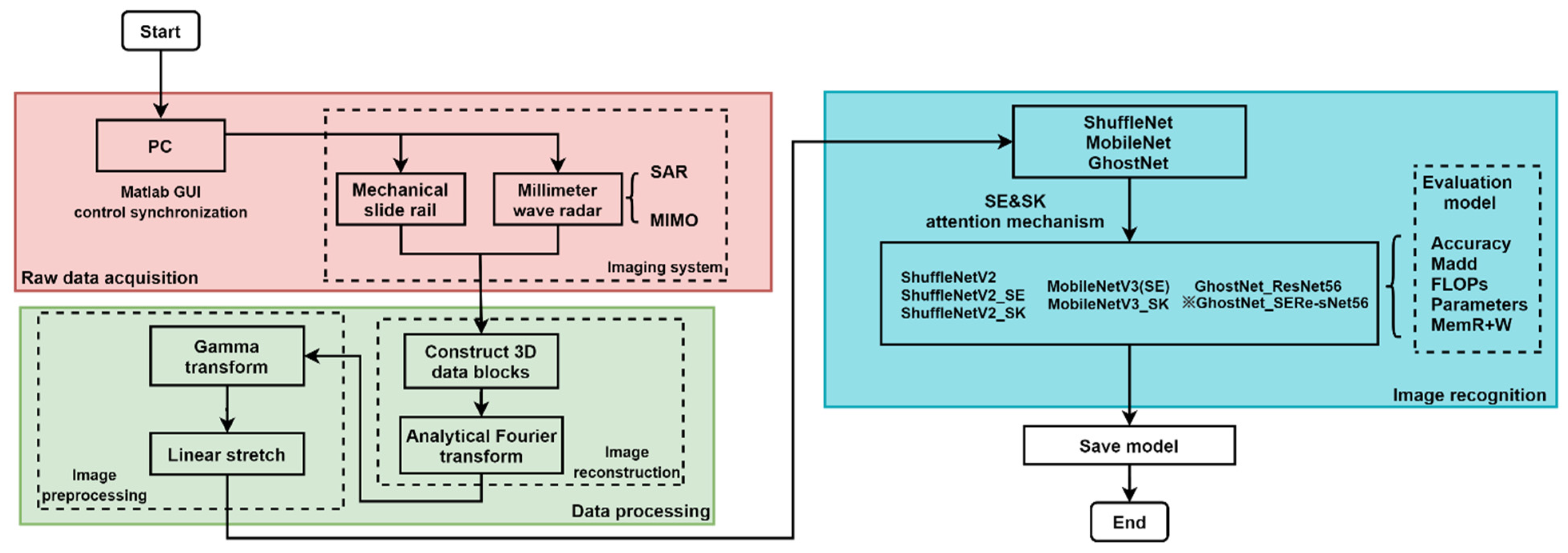
  • By using the MIMO-SAR radar, the aperture of the radar antenna is expanded to 90 mm in the X-axis direction. Eight virtual channels are established in the Y-direction, which widens the length of the longitudinal direction aperture in each transverse scanning can be equivalent to 4 λ . Image resolution can reach 1.90 mm in X-direction and 1.73 mm in Y-direction, when the object is 90 mm away from the radar. The MIMO-SAR imaging system can effectively reduce the scanning time cost, the system economic cost and improve the image resolution.
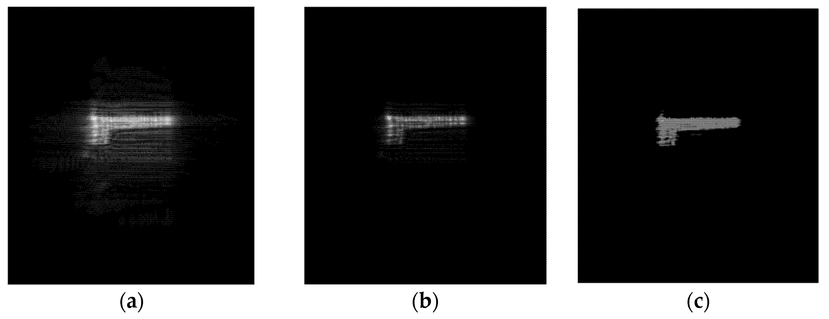
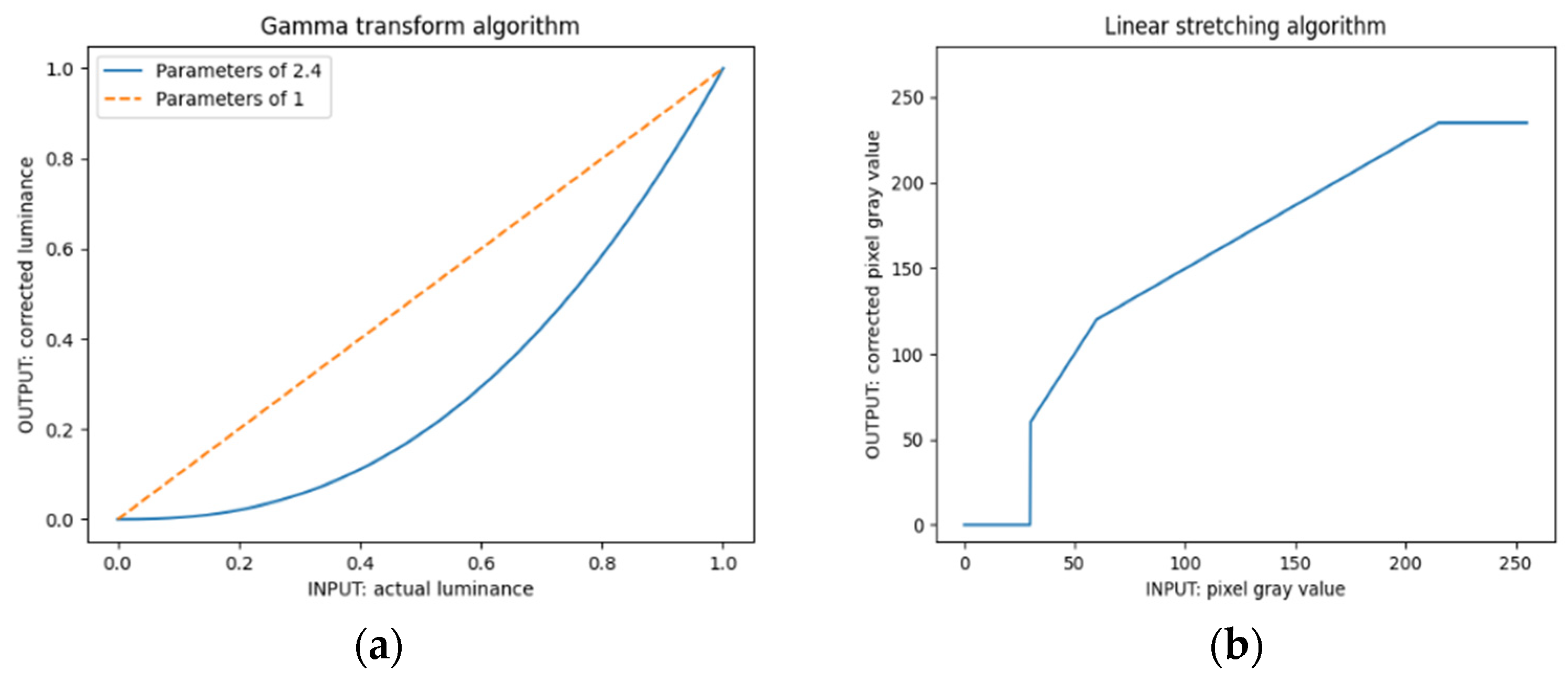
  • Gamma transform with a coefficient of 2.4 and linear stretch processing are innovatively carried out for the SAR images to remove the noise caused by distance error and improve visual recognition, which lays a good foundation for the subsequent supervised learning network.
  • The lightweight convolutional neural network is small in size and occupies less resources, but the prediction accuracy is not high. After the optimization of the SE and SK attention mechanism, the prediction accuracy is improved with the increase of a small part of the resource occupancy rate. Combined with the prediction accuracy; computational complexity: Madd, FLOPs; memory occupation rate: MemR + W, parameters. GhostNet_SEResNet56 is the optimal prediction algorithm for SAR data set, which prediction accuracy of the validation set is 98.18%; computational complexity: 134.55 MMadd and 67.81 MFLOPs; memory occupation rate: 18.98 MB (MemR + W) and 0.45 M (parameters).

Author Contributions

Conceptualization, J.L.; methodology, K.Z.; software, Z.S. and H.W.; validation, Z.S. and H.W.; formal analysis, K.Z., W.H.; investigation, Q.W., Z.S.; resources, J.L.; data curation, Q.W., W.H.; writing—original draft preparation, K.Z.; writing—review and editing, J.L.; supervision, W.H.; project administration, Q.W.; funding acquisition, H.W. All authors have read and agreed to the published version of the manuscript.

Funding

This work was supported by National Natural Science Foundation of China (11527801, 20222201 and 61305026) and Beijing Municipal Commission of Education (KM200710005009, PXM2009_014204_09_000154 and KM201310005006).

Institutional Review Board Statement

Not applicable.

Informed Consent Statement

Not applicable.

Data Availability Statement

Not applicable.

Acknowledgments

Thanks to Tianyang Gao for helping us build image training set.

Conflicts of Interest

The authors declare no conflict of interest.

References

  1. Li, C.J.; Ling, H. High-resolution, downward-looking radar imaging using a small consumer drone. In Proceedings of the 2016 IEEE International Symposium on Antennas and Propagation (APSURSI), Fajardo, PR, USA, 26 June–1 July 2016; pp. 2037–2038. [Google Scholar]
  2. Zhuge, X.; Yarovoy, A.G. A Sparse Aperture MIMO-SAR-Based UWB Imaging System for Concealed Weapon Detection. IEEE Trans. Geosci. Remote Sens. 2010, 49, 509–518. [Google Scholar] [CrossRef]
  3. Turppa, E.; Kortelainen, J.M.; Antropov, O.; Kiuru, T. Vital sign monitoring using FMCW radar in various sleeping scenarios. Sensors 2020, 20, 6505. [Google Scholar] [CrossRef] [PubMed]
  4. Tian, G.Y.; Al-Qubaa, A.; Wilson, J. Design of an electromagnetic imaging system for weapon detection based on GMR sensor arrays. Sens. Actuators A Phys. 2012, 174, 75–84. [Google Scholar] [CrossRef]
  5. Smith, J.W.; Yanik, M.E.; Torlak, M. Near-Field MIMO-ISAR Millimeter-Wave Imaging. In Proceedings of the 2020 IEEE Radar Conference (RadarConf20), Florence, Italy, 21–25 September 2020. [Google Scholar] [CrossRef]
  6. Rezaei, M.; Zamani, H.; Fakharzadeh, M.; Memarian, M. Quality improvement of millimeter-wave imaging systems using optimized dual polarized arrays. IEEE Trans. Antennas Propag. 2021, 1. [Google Scholar] [CrossRef]
  7. Richards, M.A. A beginner’s guide to interferometric SAR concepts and signal processing [AESS tutorial IV]. IEEE Aerosp. Electron. Syst. Mag. 2007, 22, 5–29. [Google Scholar] [CrossRef]
  8. Bliss, D.; Forsythe, K. Multiple-input multiple-output (MIMO) radar and imaging: Degrees of freedom and resolution. In Proceedings of the Thrity-Seventh Asilomar Conference on Signals, Systems & Computers, Pacific Grove, CA, USA, 9–12 November 2003; Volume 1, pp. 54–59. [Google Scholar]
  9. Tapia, S.L.; Molina, R.; de la Blanca, N.P. Detection and localization of objects in Passive Millimeter Wave Images. In Proceedings of the 2016 24th European Signal Processing Conference (EUSIPCO), Budapest, Hungary, 29 August–2 September 2016; pp. 2101–2105. [Google Scholar]
  10. Ran, H.; Wen, S.; Wang, S.; Cao, Y.; Zhou, P.; Huang, T. Memristor-Based Edge Computing of ShuffleNetV2 for Image Classification. IEEE Trans. Comput. Des. Integr. Circuits Syst. 2021, 40, 1701–1710. [Google Scholar] [CrossRef]
  11. Guo, R.; Xie, X. Object detection method of autonomous vehicle based on lightweight deep learning. In SAE Technical Paper Series; SAE International: Warrendale, PA, USA, 2021. [Google Scholar]
  12. Wei, B.; Shen, X.; Yuan, Y. Remote sensing scene classification based on improved Ghostnet. In Proceedings of the International Conference on Computer Science and Communication. The Journal of Physics: Conference Series; IOP Publishing: Bristol, UK, 2020; Volume 1621. [Google Scholar]
  13. Feng, S. Signal Processing Algorithm and Implementation of Millimeter Wave Active Detection System. Master’s Thesis, Nanjing University of Technology, Nanjing, China, March 2017. [Google Scholar]
  14. Fan, B.; Gao, J.-K.; Li, H.-J.; Jiang, Z.-J.; He, Y. Near-fifield 3D SAR imaging using a scanning linear MIMO array with arbitrary topologies. IEEE Access 2020, 8, 6782–6791. [Google Scholar] [CrossRef]
  15. Texas Instruments. The Overview of the TI’s mmWave Sensors. Available online: http://www.ti.com/sensors/mmwave/overview.html. (accessed on 24 September 2021).
  16. Zhuge, C.; Yarovoy, A.G. Three-dimensional near-fifield MIMO array imaging using range migration techniques. IEEE Trans. Image Process. 2012, 21, 3026–3033. [Google Scholar] [CrossRef] [PubMed]
  17. Ng, B.P.; Lie, J.P.; Er, M.H.; Feng, A. A Practical Simple Geometry and Gain/Phase Calibration Technique for Antenna Array Processing. IEEE Trans. Antennas Propag. 2009, 57, 1963–1972. [Google Scholar] [CrossRef]
  18. Stolt, R.H. Migration by Fourier transform. Geophysics 1978, 43, 23–48. [Google Scholar] [CrossRef]
  19. Kollem, S.; Rama, L.; Reddy, K. Modified transform-based gamma correction for MRI tumor image denoising and segmentation by optimized histon-based elephant herding algorithm. Int. J. Imaging Syst. Technol. 2020, 30, 1271–1293. [Google Scholar] [CrossRef]
  20. Ma, N.; Zhang, X.; Zheng, H.; Sun, J. ShuffleNet V2: Practical guidelines for efficient CNN architecture design. In Proceedings of the European Conference on Computer Vision; Springer: Cham, Switzerland, 2018. [Google Scholar]
  21. Qian, S.; Ning, C.; Hu, Y. MobileNetV3 for image classification. In Proceedings of the 2021 IEEE 2nd International Conference on Big Data, Artificial Intelligence and Internet of Things Engineering (ICBAIE), Nanchang, China, 26–28 March 2021; pp. 490–497. [Google Scholar]
  22. Han, K.; Wang, Y.; Tian, Q.; Guo, J.; Xu, C.; Xu, C. GhostNet: More features from cheap operations. In Proceedings of the IEEE/CVF Conference on Computer Vision and Pattern Recognition (CVPR), Seattle, WA, USA, 14–19 June 2020; pp. 1580–1589. [Google Scholar]
  23. Hu, J.; Shen, L.; Albanie, S.; Sun, G.; Wu, E. Squeeze-and-Excitation Networks. IEEE Trans. Pattern Anal. Mach. Intell. 2020, 42, 2011–2023. [Google Scholar] [CrossRef] [PubMed] [Green Version]
  24. Li, X.; Wang, W.; Hu, X.; Yang, J. Selective kernel networks. In Proceedings of the 2019 IEEE/CVF Conference on Computer Vision and Pattern Recognition (CVPR), Long Beach, CA, USA, 15–20 June 2019; pp. 510–519. [Google Scholar]
  25. He, J.; Jiang, D. Fully automatic model based on SE-resnet for bone age assessment. IEEE Access 2021, 9, 62460–62466. [Google Scholar] [CrossRef]
Figure 1. Flow chart of millimeter wave radar imaging and target recognition system.
Applsci 11 08926 g001
Figure 2. Radar test target distance.
Applsci 11 08926 g002
Figure 3. Z scanning track.
Applsci 11 08926 g003
Figure 4. (a) Displacement map of virtual channel in Y-direction; (b) the antenna of single transmitter and single receiver is compared with that of multiple transmitter and multiple receiver.
Applsci 11 08926 g004
Figure 5. Radar three-dimensional data block and the schematic diagram of extracting two-dimensional data block under a fixed Y-direction displacement.
Applsci 11 08926 g005
Figure 6. Millimeter wave radar detects hidden targets.
Applsci 11 08926 g006
Figure 7. (a) The actual picture of scissors covered by paper box; (b) SAR image of scissors covered by paper box 90 mm from radar.
Applsci 11 08926 g007
Figure 8. Part of the original data sets and the corresponding SAR radar images.
Applsci 11 08926 g008
Figure 9. (a) Gamma transform algorithm with coefficient of 2.4; (b) linear stretch algorithm.
Applsci 11 08926 g009
Figure 10. (a) Reconstruction of the image; (b) gamma transform algorithm with coefficient of 2.4 is used to process the original image; (c) the original image is linear stretching algorithm after gamma algorithm.
Applsci 11 08926 g010
Figure 11. ShuffleNetV2 network structure.
Applsci 11 08926 g011
Figure 12. Ghost network structure.
Applsci 11 08926 g012
Figure 13. GhostNet_ResNet56 confusion matrix on the SAR validation set.
Applsci 11 08926 g013
Figure 14. SE attention mechanism optimizes GhostNet_SEResNet56 network.
Applsci 11 08926 g014
Figure 15. (a) GhostNet_SEResNet56 confusion matrix on the SAR validation set; (b) comparison of prediction accuracy of GhostNet_ResNet56 network and GhostNet_SEResNet56 network with Epoch changes.
Applsci 11 08926 g015
Table 1. Experimental results of object distance measurement.
Target Distance0.35 m0.5 m0.75 m
First round measurement0.36 m0.51 m0.76 m
0.34 m0.51 m0.76 m
0.35 m0.52 m0.75 m
Second round measurement0.34 m0.52 m0.75 m
0.35 m049 m0.76 m
0.35 m0.51 m0.74 m
Table 2. X, Y axis mechanical control parameters and target distance.
Parameter NameValue/Unit
Num_horizontalScan180 points
Num_longitudinalScan13 points
Horizontal_scanSize_mm90 mm
Longitudinal_scanSize_mm98.67 mm
Horizontal_stepSize_mm0.500 mm
Longitudinal_stepSize_mm7.590 mm
Platform_Speed_mmps20 mm/s
Z090 mm
Table 3. Radar setting parameters.
ParameterValue
RxToEnable[1,2,3,4]
TxToEnable[1,2,3]
Slope_MHzperus70.295
Samples_per_Chirp256
Sampling_Rate_ksps5000
Num_Frames1
Chirps_per_Frame1
Frame_Repetition_Period_ms25.000
Table 4. Comparison of prediction results and performance of three series lightweight neural network.
Object Recognition AlgorithmAccuracy
(Valid)
Madd
(MMadd)
Parameters
(M)
FLOPs
(MFLOPs)
MemR + W
(MB)
ShuffleNetV284.55%284.891.26144.1647.32
ShuffleNetV2_SE87.27%285.151.40144.3047.85
ShuffleNetV2_SK89.09%293.941.69148.8556.51
MobileNetV3(SE)96.36%115.411.2458.6030.93
MobileNetV3_SK98.18%119.981.3060.9956.51
GhostNet_ResNet5695.45%134.540.4467.8018.95
GhostNet_SEResNet5698.18%134.550.4567.8118.98
Publisher’s Note: MDPI stays neutral with regard to jurisdictional claims in published maps and institutional affiliations.

