Abstract
To study the effect of a bird striking engine fan on the rotor system, a low-pressure rotor system dynamic model based on a real aero-engine structure was established. Dynamic equations were derived considering the case of the bird strike force which transferred to the rotor system. The bird strike force was obtained from the bird strike process simulation in LS-DYNA, where a smoothed particle hydrodynamics (SPH) mallard model was constructed using a computed tomography (CT) scanner, and finite element method (FEM) was used to simulate the bird strike on an actual fan model. The dynamic equations were solved using the Newmark-β method. The effect of rotational speeds on the rotor system dynamics after bird strike was investigated and discussed. Results show that the maximum bird impact force can reach 104 kN at 3772 r/min. Impact time is only 0.06 s, but the bird strike on fan blades lead to a transient shock on the rotor system. Under the action of transient shocks, the rotor system displacement in the horizontal and vertical directions increase sharply, and the closer the mass point is to the fan, the more it is affected; the vibration amplitude at the fan will increase 15 times within 0.1 s of the bird strike and will gradually decrease with the effect of damping. The dynamics of the rotor system changes from a stable single periodic motion to a complex irregular quasi-periodic motion after a bird strike, and the strike force excites the first-order vibrational mode of the rotor system. This phenomenon occurs at all speeds when bird strikes occur. Bird strikes will cause resonance in the rotor system, which may cause damage to the engine. It was also seen that the bird strike force, and hence the effects on the rotor system, increases as the engine rotational speed increases; the peak force is larger and the number of peaks has increased. The impact force at 3772 r/min is 99.5 kN higher than at 836 r/min, and three additional peaks emerged. This effect is more reflected in the amplitude, and the overall vibration characteristics do not change. Combining the bird strike with the rotor dynamics calculation, the dynamic response of the aero-engine rotor system to bird strike is studied at different flight stages, which is of guiding significance for power evaluation of aero engines after bird strike.
1. Introduction
The bird strike is a common hazard of aircraft which has a significant effect on their operation safety. According to the statistics of the Federal Aviation Administration (FAA), wildlife strikes have damaged more than 271 aircraft and have led to more than 292 deaths worldwide between 1988 and 2019 [1]. As shown in Figure 1a, the wildlife strike frequency on aircraft has been constantly increasing since 1990. In 2019, 17,760 wildlife strikes took place, among which the proportion of bird strike was 94.4%. As shown in Figure 1b, the proportion of engine damage is the highest, reaching 26%, namely, the aero engine is a frequent occurrence area for bird striking [2]. When a bird impacts a jet engine, the fan is struck first, which may cause the failure of fan blades and induce secondary faults. Research on the effect of bird strike on the operation of an aero engine is of great importance to the working safety and reliability of the aero engine.
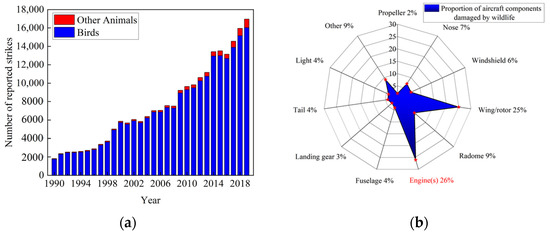
Figure 1.
Number of wildlife strikes to civil aircraft and the proportion of civil aircraft components damaged by wildlife: (a) number of wildlife strikes to civil aircraft during 1990–2019, (b) proportion of civil aircraft components damaged by wildlife during 1990–2019.
In early bird strike studies, experimental methods were the most valid and popular means of gaining knowledge about bird strike. However, the experimental tests are expensive and difficult to perform [3]. Therefore, numerical simulation methods have been widely used and fully developed in the past 30 years [4]. Several simple geometries have been adopted to represent the shape of a bird. The geometry of the substitute bird models are of four main types: straight-ended cylinder, hemispherical-ended cylinder, ellipsoid, and sphere [5,6]. The hemispherical-ended cylinder has been the most commonly used geometry due to its more accurate results [7]. More recently, bird models with realistic geometries based on CT scan images have replaced the geometric model due to the more accurate results [8,9].
In the early simulations based on finite element analysis, the bird impact load was modelled as a uniform pressure vs. time at the impact area [10]. Afterwards, bird models based on Lagrangian, Eulerian, Arbitrary Lagrangian–Eulerian (ALE), and Smoothed Particles Hydrodynamics (SPH) formulations were developed and used in the bird strike simulations [11,12,13,14,15,16,17,18].
As for the target fan model, the initial approach was to use a plate with a thickness [19,20]. In more recent studies, fan blades with realistic geometries have become more common, whereafter transient response of rotating is obtained under bird-slicing impact [21,22,23]. Meanwhile, different cases of bird strikes with different bird mass and velocity, impact location and timing, and rotary speed have been investigated on the rotary engine [24,25]. In this paper, the SPH bird impactor model has been chosen and the finite element method on a fan model with realistic geometry is applied.
Bird strikes often have a dramatic effect on the aircraft’s engines. The impact dynamics analysis under bird strike (which can be considered as foreign object impacts) can cause severe deformation in the fan blades, leading to impact-induced force generation [21]. Bird strike experiments on the engine primary compressor under different bird strike conditions were investigated by Liu et al., and a significant effect on the engine performance was found [24]. A bird strike creates a substantial impact force, which may apply significant imbalanced loads on the fan shaft, leading to problems occurring in the rotor performance [26].
Transient impacts on the rotor system can affect the stability of the whole system. Adding shock excitation to the bearing location of the rotor system can result in a significant impact on the rotor system [27]. The transient impact caused by airflow excitation has an obvious influence on the dynamic response of the rotor system [28]. Meanwhile, the engine rotates at high speed and its response is subjected to sudden unbalanced forces that have been studied [22]. Bird strike will not only apply transient impact load, but also induce rubbing between fan and casing [29]; then, a more common phenomenon has emerged. Transient shocks caused by rub-impact have been widely studied, and most studies have investigated the transient dynamic response and nonlinear characteristics of the system by introducing a rub-impact system model into the rotor system [30,31,32], the rub-impact model from the simple rotating static sub rubbing [33], development for the blade-casing rubbing [34,35,36], and the now widely used blade-coating rubbing [37]. Different models produce different transient shocks and have different magnitudes of impact on the rotor, but all studies could illustrate the high susceptibility of rotor systems to transient shocks, leading to changes in operating conditions. In most studies [33,34,37,38,39], the impact load is often added to the dynamic equation as a function. The response of rotor dynamic is complicated when impact loads are added to the equation. However, as impact loads are often irregular, and hard to be described by the equations for some cases, this may lead to the difference between numerical results and actual responses of the rotor system. In this paper, to overcome the irregularity of bird impact force and the difficulty of fitting the equation, the impact force obtained by simulation is added to the equation by interpolation.
From the above-mentioned studies, it is evident that, even though in many previous studies transient shocks have been introduced into the rotor systems, only a limited number of models have directly incorporated bird impact forces into the dynamics calculations. This is despite the fact that the bird impact forces are also a distinct transient force that can have severe effects on rotor systems. Therefore, in this paper, based on the simulation of the bird strike engine fan process, the scope of the research is limited to the deformation of the fan blades due to bird strike, and the case of the blade out is excluded. The impact force generated by the bird strike on the system is obtained, and the dynamic response of the rotor system before and after the occurrence of the bird strike is analyzed, which provides some reference for the study of the rotor impact mechanics of the bird strike engine.
2. Bird Strike and Rotor Dynamic Modeling
2.1. Bird Strike Modeling
According to the statistical report from FAA [1], during 1990–2019, mallards struck aircraft a total of 1146 times, making it one of the birds with the highest frequency of collisions with aero-engines. Therefore, the mallard was taken as the prototype bird model. The weight of the selected mallard was 820 g with 40 cm in body length and a 45 cm wingspan. The mallard bird was scanned by the CT scan device at a medical imaging center. A total of 1566 DICOM (Digital Imaging and Communications in Medicine) images were obtained. DICOM images and the SPH method were adopted to model the mallard. During the modeling process, the internal cavities of the mallard bird were considered, and no SPH elements were used in such areas. The final model composed of 41,685 SPH elements each weighing 0.0191 g (Figure 2).
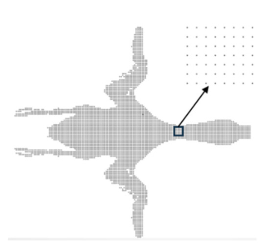
Figure 2.
Mallard bird model used in numerical simulation.
The bird was endowed with a Null material model with Gruneisen equation of state (EOS) [5,40]; the viscous stress was calculated by providing the intrinsic relationship of the model. The state equation was used to calculate the pressure, with the material initial density of 938 kg/m3 [40]. Based on the EOS [41], the pressure of the compressed material is defined as follows:
For expansion of the material, the pressure is expressed as:
Where C is the intercept of the velocity curve; S1, S2, and S3 are the slope coefficients of the velocity curve; is the Gruneisen constant; a is the first-order volume correction to ; E is the Elastic Modulus of material; and is the reference density. The parameter is defined by:
where is density of the material. Based on Ref [42], the EOS’s parameters of C = 1480, S1 = 1.92, S2 = 0, S3 = 0, and were used.
A type of aero turbofan engine fan system is demonstrated in Figure 3. The fan system consisted of 24 narrow chord blades. The height of each blade was 603.2 mm, and the initial torsion angle was 61.3°. The blade was connected to the hub with a dovetail and tongue-and-groove mating method. The entire fan system was discretized using 1,520,208 hexahedral solid elements (3 mm in size), see Figure 3. The material properties of Ti-6Al-4 V alloy with plastic dynamics model (MAT_PLASTIC_KINEMATIC) was employed for the fan blade (Table 1).
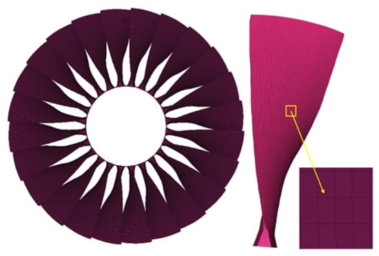
Figure 3.
Finite element model of turbofan engine fan.

Table 1.
Blade material parameters.
When a bird hits the fan blade, there is an uncertainty in the impact location, and different impact locations led to different damage effects [43]. To better reflect the effect of impact forces on the rotor system, a single impact location was selected for the simulations. The same applies to the selection of the impact orientations. Five impact positions: 1/6, 1/3, 1/2, 2/3, and 5/6 fan blade height, and 15 types of impact orientations were considered. Based on the previous studies [44], the bird impact force is pronounced at 1/2 blade height, which leads to significant impact on the rotor system. Therefore, 1/2 fan blade height as the impact position and the head side as the orientation were chosen, which is given in Figure 4.
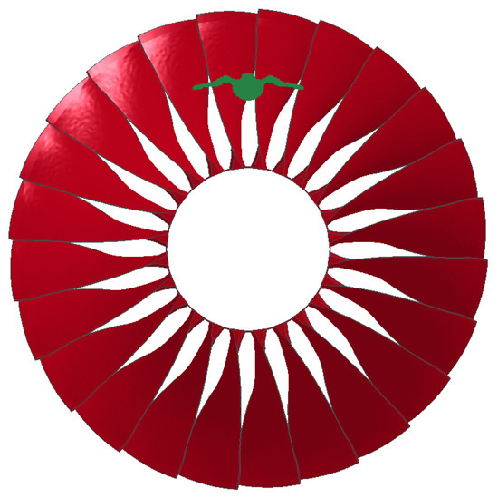
Figure 4.
The selected impact position and bird orientation.
In the simulation, the sucked-in velocity of the bird was 116 m/s. Some of the previous studies [5] on the bird impacting fan did not take the rotation of the fan into account, namely, the blades were stationary. As a result, two problems that made the simulation deviate the actual impact process arose: (1) the dynamic stiffening effect on the blade due to the centrifugal force was ignored; (2) the direction of the contact force was constant, as the relative velocity between the bird and the blade was not considered. For a more realistic simulation of the bird strike onto the fan, the rotor system was run at different rotational speeds. Bird strike occurs in several stages of flight [1]. The differences of fan speed at each stage leads to the different dynamic responses of the fan blade and thus the rotor system. According to the fan rotation speed in QAR (quick access recorder) data of an aero engine, four rotational speeds were 836 r/min, 3772 r/min, 3344 r/min, and 1984 r/min corresponding to five typical operating conditions of the ground idle stage, approaching stage, climbing stage, cruising stage, and descending phase. The noted speeds were selected as the initial fan rotational velocities. The bird model was verified by comparing the numerical results with Wilbeck’s experimental results [41,45].
Comparing the experimental data of Wilbeck, the simulation data of the traditional model (sphere model), and the mallard model built in this paper, we monitored the pressure magnitude of the model after striking on the target. From Figure 5, when using the mallard model, the magnitude of the pressure values and the pattern of its variation with time are close to those of the Wilbeck’s experiment compared to the conventional model. The pressure difference does not exceed 15%, other than the peak value, so the bird collision model can be considered to reflect the real bird collision process to some extent.
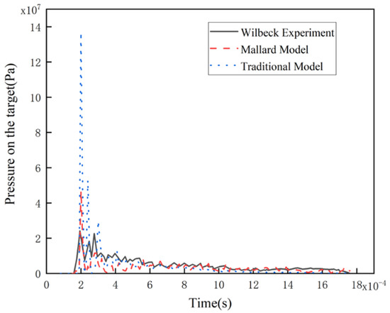
Figure 5.
Pressure profile on the target of impact under three different impact conditions.
2.2. Rotor System Modeling
The operation state of an aero engine may be affected by the impact force caused by a bird strike. Understanding the response characteristics of the rotor system under bird strike is useful for grasping the aero-engine operation state. The key to studying the dynamic response of an aero-engine rotor system is to develop a rotor dynamics model that can describe the effects of bird strikes on the fan blade. The schematic diagram of the aero-engine low-pressure rotor system is depicted in Figure 6. The low-pressure rotor system is supported by three rolling bearings (#1, #2, and #3), including a 1-stage fan and a 4-stage low-pressure turbine, and the bearing supporting mode is “0-2-1”.

Figure 6.
Schematic diagram of aero-engine low-pressure rotor structure and its support system.
To establish an accurate rotor dynamics model, three coordinate scanning and 3D modeling of the rotor shaft, disk, and other components were carried out: first, BESTSCAN 751 (HOLON 3D, China) 3D scanner and HL-Scan software were used to obtain the point cloud data of the components, and the data was then imported into the software CATIA for constructing 3D models. Combined with the material parameters of each component, the mass distribution and center of mass position of the rotor system were obtained. Based on the obtained data points, the fan, the shaft, and the disk were simplified as several mass elements through the lumped-mass method, and a low-pressure rotor system model of the aero engine was established, as shown in Figure 7.
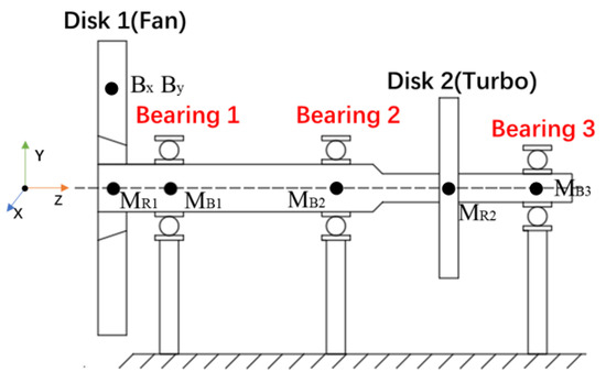
Figure 7.
The dynamical model of rotor system.
When using the lumped-mass method, the blade and the disk are treated as a mass point, so the bird impact force is considered to the disk, and its actual impact on the blade is similar; the mass of the disk is much larger than the mass of the mass point on the shaft, and the influence of its eccentricity is much larger than the eccentricity of the shaft, so the influence of concentrating the eccentricity on the disk on the calculation results is accepted. As there is no need to consider the connection method of each component in the calculation, considering it as a whole will have no effect on the calculation results; as only the x and y directional displacement of the rotor is considered in this paper, the torque is ignored in the simplification; and as the maximum speed is 3772 r/min and the speed is low, the influence of the gyroscopic force is not obvious, therefore ignoring these two items has little influence on the calculation results.
As the focus of this research was the effect of bird strike on the rotor system in the x–y plane of radial vibration, other vibrational effects were not taken into account, and the following assumptions were considered:
- The force from the bird strike was taken into account on the disk.
- The unbalanced mass of the rotor system concentrated on the two rotor disks, and the mass of the rotor system was discretized into the five mass points on the shaft.
- The materials of the blade and the disk behave according to Hooke’s law.
- The blade, disk, and shaft were considered to be rigidly connected to each other, ignoring the connections between them.
- The torsional vibration and gyroscopic moment of the system were neglected.
Based on Newton’s second law, the equations of motion for the established rotor system were derived as:
where MR1 is the mass of Disk 1 of the rotor, MR2 is the mass of Disk 2, and MB1, MB2, MB3 are the masses of the concentrated points at the three rolling bearings, respectively. CR and CB are the damping coefficients of the disk and ball bearings, Kr is the stiffness of the shaft, supposing that the stiffness of each section of the rotor is identical. eR1 and eR2 are the eccentricities of Disk 1 and Disk 2, respectively. Bx and By are the decomposition of bird impact forces into the x and y directions, respectively. FBix and FBiy (i = 1, 2, 3) are the bearing support forces in the x and y directions. is the rotational speed of the rotor in rad/s.
As this paper mainly studies the impact of bird strike on the fan rotor system, the bearings are regarded as an elastic system. The bearing stiffness in the rotor system was considered to be constant (Kb). The equations relating FBix and FBiy (i = 1, 2, 3), stiffness, and displacements could be given by:
From the above equations, the bearing support force is proportional to the displacement, and the negative sign indicates that the reaction force points in the opposite direction of the displacement.
In our previous study [31], we used the same 3D scan method to build a ‘0-2-1’ rotor test setup using the kinetic similarity principle (see Figure 8). The vibration response of the rotor system at 1500 rpm was measured using a test rig and is shown in Figure 9a. At a speed of 1500 r/min, the vibration waveform of the system shows obvious peaks at the peaks and valleys. The fundamental frequency amplitude is the main frequency of the rotor system, and its amplitude is much larger than other high frequencies. The numerical method is used to calculate the rotor response at 1500 r/min, as shown in Figure 9b, and it can be found that some of the results are the same, differing in units due to different model simplification treatments, which verifies the accuracy of the proposed rotor system model to a certain extent.
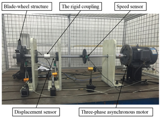
Figure 8.
The rotor test rig.
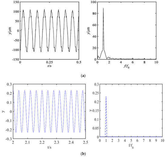
Figure 9.
The vibration response of normal rotor system at 1500 r/min: (a) test rig (b) numerical calculation.
3. Results and Discussions
3.1. Bird Strike Force at Different Rotational Speeds
The bird strike simulation was performed in LS-DYNA to obtain the impact forces transmitted to the rotor system. The bird state at different times during the impact process is shown in Figure 10, and it shows that the bird body SPH model has been cut into particles after the strike.
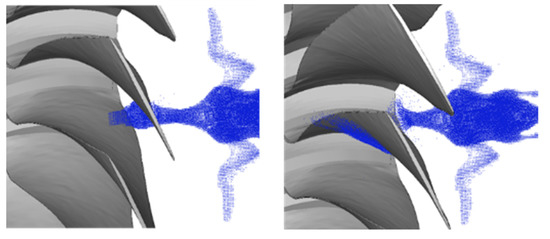
Figure 10.
The bird state at different times during impact process.
The bird strike process was simulated at four rotational speeds, and the contact forces in the x and y directions (in coordinate system depicted in Figure 7) are extracted and shown in Figure 11.
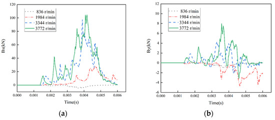
Figure 11.
The bird impact forces at four rotational speeds: (a) in the X direction, and (b) in the Y direction.
Figure 11 shows that the peaks of the magnitude of the bird impact forces in both the x and y directions increase with the rotational speed of the rotor. Moreover, the force in the x direction is significantly larger than that in the y direction, which is caused by the geometry of the fan blade.
The curve at 3772 r/min includes several peaks, which is due to the splitting of the bird body into multiple pieces by the fan blades during the impact process. The magnitude of each peak is highly dependent on the size of the colliding bird body. The number of peaks varies at different speeds, which is due to the fact that the number of blades cutting the bird body varies with the fan rotational speed. The faster the fan rotates, the more blocks the bird body is divided into and, as a result, the more peaks appear. Additionally, is it notable that the direction of the force changes in some curves, especially in the y direction at the speed of 1984 r/min. This is as the strike process between the bird body and the blade can be divided into two parts. As the fan is rotating, the bird hits the blade, which results in the blade slapping the bird body. As can be seen in Figure 10, after the bird was cut by the fan, the blades may hit the bird body, thus causing a change in the direction of the force in Figure 8.
After obtaining the curve of variation of Bx and By with time, the data were substituted into the dynamic equation by linear interpolation method to calculate the rotor dynamic responses.
3.2. Numerical Simulation of Rotor System Dynamic
The second-order differential equations of motion of the rotor system were solved with the Newmark- method. The required data are listed in Table 2.

Table 2.
The geometrical and material parameters of rotor system.
In Table 2, is the clearance of the ball bearing for the non-dimensional calculations. To facilitate the presentation of the results, some data has been dimensionless. The dimensionless displacement parameter is defined as and , the dimensionless speed parameter is given by and , and the dimensionless acceleration parameters are calculated by and .
A total of 400 calculation cycles were performed. Considering the volatility of the calculation, in this research, the bird impact force was added to the calculations after the rotor system results were stabilized. The bird impact force was added at to the calculations when the rotor system had sufficient time to be stabilized. The displacement, velocity and acceleration data of each mass point of the rotor system were obtained. The orbit plot, the Poincaré section map, the phase diagram, the time domain map, and the spectrogram were used to illustrate the dynamic response of the rotor system after bird strike.
3.3. The Dynamic Responses of Rotor System Fan before and after Bird Strike
The dynamic responses of the rotor system fan before and after bird strike are demonstrated in Figure 12. Figure 12a depicts the variations of the rotor displacement in the x direction vs. time in the steady-state operational condition when the bird strike has not yet occurred (). The periodic fluctuations of displacement in the x direction come from the interaction of eccentric force, stiffness and damping of the system. The system runs smoothly during this duration and the maximum dimensionless displacements remains constant at 0.8. Similarly, in Figure 12c, the same periodic motion can be observed, but in the y direction. With an initial displacement in the y direction due to the gravitational force, the amplitude range is −1.68 to −2.98. The system operated smoothly before the bird strike occurs. Figure 12e shows the axial rotation of the system in the steady-state operation, with the axis of the fan moving in the range of approximately −0.8 to 0.8 in the x direction and −3 to −1.8 in the y direction. The axial rotation remains constant as a closed and relatively regular circle.
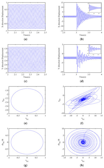
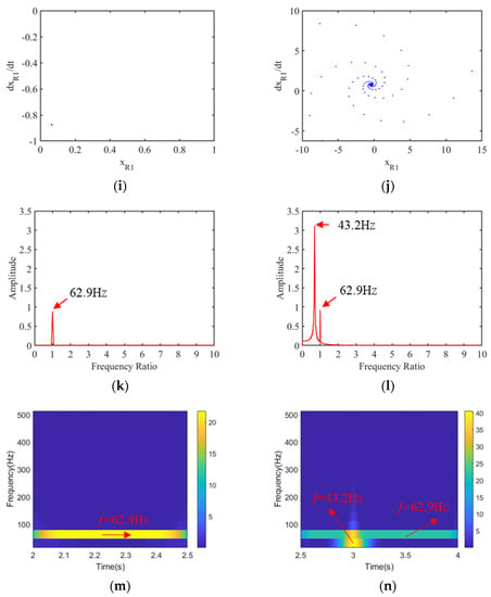
Figure 12.
The dynamic response of rotor system fan before and after bird strike at 3772 r/min: (a) time history of displacement before bird strike in the X direction, (b) time history of displacement after bird strike in the X direction, (c) time history of displacement before bird strike in the Y direction, (d) time history of displacement after bird strike in the Y direction, (e) axis orbit before bird strike, (f) axis orbit after bird strike, (g) phase diagram before bird strike, (h) phase diagram after bird strike, (i) the Poincaré section before bird strike, (j) the Poincaré section after bird strike, (k) frequency spectrum before bird strike, (l) frequency spectrum after bird strike, (m) time-frequency graph before bird strike, and (n) time–frequency graph after bird strike.
Figure 12g shows the phase diagram of the rotor operation, where the trajectory line is demonstrated as a closed limit ring, indicating that the system has a single periodic motion. There is also only one isolated point in the Poincaré section map in Figure 12i. Both diagrams in Figure 12g,i indicate that the rotor system undergoes a stable single periodic motion before bird strike. It can be seen from Figure 12k that there is no other frequency component, except the fundamental frequency in the spectrum graph, which confirms the correctness of the previous graph. It would be intuitive to investigate the effect of the bird strike on the noted graphs.
Figure 12b,d depict the horizontal and vertical time history of the fan displacement after the occurrence of bird strike at . In the x direction, due to the influence of the applied bird impact excitation, the amplitude of the rotor displacement changes dramatically after , with a maximum dimensionless amplitude close to 15 in the x direction. In the y direction, the maximum displacement amplitude increases for around 3.7 times compared to the initial position, which is due to the larger bird impact force in the x direction. The difference between the x direction and y direction displacements before and after the bird strike demonstrates that the magnitude of the bird impact force has a direct effect on the displacement of the fan rotor. Looking at the plots from to , it can be seen that the amplitude of the rotor displacement is modulated after the onset of the shock, showing the multi periodic motion and the response amplitude gradually decreases under the effect of damping, and that the motion is eventually is smoothed out and goes back to the situation before the impact. As the research did not consider the deformation of fan blades and the fan blade-out events during bird strike, the operation of the rotor system goes back to normal after bird strike.
From the axial orbit diagram in Figure 12f, it can be seen that, after the bird strike, the fan motion has deviated significantly from circular axial orbit curves in Figure 12e. It shows multiple chaotic intersecting curves with intense and irregular variations. The amplitude of motion also increases significantly compared to the stable operation before bird strike occurrence. However, there exists a clear stable region in the middle of the axial diagram (Figure 12h). Meanwhile, it can be seen from the phase diagram (Figure 12h) that there are multiple limit rings of motion during this period, that the situation is chaotic, and that several overlapping situations occur. At the end of bird strike phenomenon, a stable limit ring appears in the middle of the phase diagram (Figure 12h) and Poincaré section map (Figure 12j). There are several points in the Poincaré section map due to the bird strike, which indicate multiple cycles of the motion which gradually converge to a fixed position.
From above-mentioned analysis, it can be concluded that a bird strike on an aero-engine operating at 3772 r/min causes a strong transient impact on the rotor system, and that the rotor motion will be greatly disturbed, affecting the normal operation of the rotor. However, due to the instantaneity of the impact, the rotor system gradually regains its stability due to damping effect after the shock. It can be seen in Figure 12l that after the rotor is impacted by the bird, the rotor rotation frequency still exists, even though it has a slight increase in amplitude compared to stable operation. A sharp peak is produced at frequency of 43.2 Hz. This frequency is independent of the fundamental frequency, which is due to the bird strike exciting the first mode of the rotor. The time–frequency graph of the dynamic response before and after bird strike in the x direction is demonstrated in Figure 12m,n. During , the frequency band in the graph is concentrated on the position of the rotational frequency, as the bird strike had not occurred at this time. After the bird strike occurring at 3 s, a clear abrupt change in frequency emerges. In addition to the fundamental frequency of 62.9 Hz, a frequency of 43.2 Hz has appeared, which is approximately equal to the first-order mode. The first-order response of the rotor system (43.2 Hz) was excited by the transient shock caused by the bird strike.
In summary, the rotor motion becomes extremely unstable after a bird strike; therefore, corresponding measures must be taken, otherwise it will cause great harm to the normal operation of the aircraft engine.
3.4. The Dynamic Response of the Rotor System
The previous section analyzed the dynamic response of the fan position where the bird strike force acts directly, while the bird strike affects the whole rotor system. Figure 13 shows the displacement of other mass points vs. the time. Looking back at the time history of displacement diagrams of the fan in Figure 12b, the displacement amplitude of the bearings and the turbine is significantly smaller. When the fan is not hit by a bird, the dimensionless displacement amplitude is 0.87. After bird strike, the displacement rises to 14.1, an increase of 12.23. In the other mass points of the rotor, the displacements are, respectively 0.23, 0.01, 0.21, and 0.07 from the position close to the fan hub to the end of the blade before bird strike. After bird strike, the maximum displacements increase significantly to 3.97, 1.41, 1.13, and 0.38, respectively, for the noted positions. As the bird strike force directly acts on the fan hub, the closer the bird impact point to the fan hub is, the larger the maximum displacements would be.
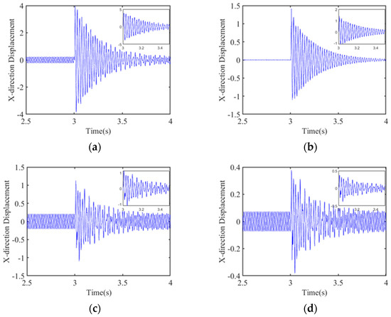
Figure 13.
The time history of displacements of different mass point positions of the rotor system. Time history of (a) bearing 1, (b) bearing 2, (c) rotor 2, and (d) bearing 3.
To study the response of the rotor system at different times, the position displacement of the rotor system at five typical instances is demonstrated in Figure 14. The effect of bird strikes on the horizontal displacement of the rotor system is obvious from the graph. At , the bird strike has not yet occurred, and the displacement of the rotor is small. When the bird strike occurs at , in a very short time, i.e., at , the overall displacement level of the rotor increases significantly. Similar to the previous conclusion, the closer the impact position to the fan position is, the greater the magnitude of the displacements increase would be. At bearing 3, which is far from the fan, the variation of displacement is very small, and the maximum displacement does not exceed 0.38. In practical studies, special attention should be paid to the response at the bearing close to the fan. At , the vibration amplitude starts to drop rapidly due to damping effect, reaching 75% at the fan. Finally, at , the displacement curve is almost identical to that at the initial steady state. Therefore, bird strike is very likely to cause damage to the engine in an instant.
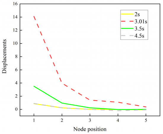
Figure 14.
The displacements of rotor system at different times.
3.5. The Influence of the Rotational Speed
The dynamic responses of the fan of the rotor system under three other rotational speeds are demonstrated in Figure 15, then a comparison between the dynamic responses was performed in conjunction with the calculation at 3772 r/min in Figure 12. The time history variations of displacement (Figure 15a–c) have the same trend as that presented in Figure 12. Due to the different magnitude of the bird strike force, the maximum value of each displacement has obvious differences and increases with rotational speed. Similar patterns can be observed in the axis orbit diagram (Figure 15d–f). The range of the axis orbit motion increases significantly with the increase in rotational speed. It can be seen from the phase diagram shown in Figure 15g–ithat the higher the speed is, the higher the number of limit rings would be. It can be seen in the Poincaré section diagram (Figure 15j–l) that, as the speed increases, more points appear in the diagram, so more periods of motion exist. From what was said above, it can be concluded that as the rotor speed increases, the impact of bird strike becomes more drastic and the time required to go back to the steady state becomes longer. From the frequency spectrum diagram shown in Figure 15m–o, the fundamental frequency of the rotor system is always present with or without bird strike, and that bird strike only causes small fluctuations in the amplitude. It is noteworthy to say that the vibrational peak occurred at around 43 Hz. As the natural frequency of the rotor is also around 43 Hz, the first-order mode of the system is excited by the bird strike, which can cause serious damage to the engine. In Figure 15p–r, the time–frequency graphs show the same results. At different speeds, first-order frequencies are excited except for the fundamental frequency. From what was said above, it can be concluded that the effect of bird strikes on the rotor system only differs in magnitude at different speeds, and there is no significant difference in vibration characteristics.
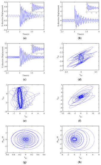
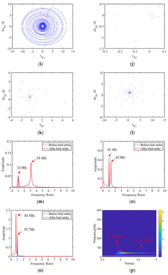
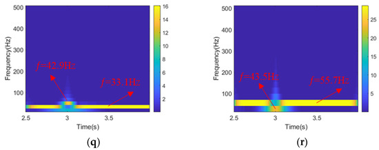
Figure 15.
The dynamic responses of rotor system fan after bird strike at 836, 1984, and 3344 r/min: Time history of displacement at (a) 836 r/min, (b) 1984 r/min, and (c) 3344 r/min; axis orbit at (d) 836 r/min, (e) 1984 r/min, and (f) 3344 r/min; phase diagram at (g) 836 r/min, (h) 1984 r/min, and (i) 3344 r/min; Poincaré section at (j) 836 r/min, (k) 1984 r/min, and (l) 3344 r/min; frequency spectrum at (m) 836 r/min, (n) 1984 r/min, and (o) 3344 r/min; time–frequency graph at (p) 836 r/min, (q) 1984 r/min, and (r) 3344 r/min.
4. Conclusions
The “0-2-1” rotor system model was modeled mathematically and combined with the bird strike force obtained from bird strike simulation in LS-DYNA; the responses of the rotor system under bird strike and at different rotational speeds were studied. The conclusions can be summarized as follows:
(1) In the process of the bird strike, due to the blade geometry, the impact force in the y direction is much smaller than that in the x direction at 3772 r/min, with a difference of about 99.5 kN. The same holds true for other operational speeds. As the bird body in the bird strike process is cut into multiple parts, there are several peaks in the bird impact force diagrams.
(2) At the climbing state, the dimensionless displacement in the x direction was 0.88 before bird strike, and it reached 14 after bird strike, which shows an increase of about 16 times. The motion type also changed from a single periodic type to irregular quasi-periodic type. The displacement of the rotor system also increased significantly, and the closer to the fan hub, the more obvious the increase in amplitude. Therefore, bird strike has a serious impact on the rotor operation.
(3) At different rotational speeds, the response of the rotor after bird strike is similar. The difference caused by speed is only reflected in the amplitude, as it leads to different impact forces. At 836 r/min, the displacement in the x direction increases from 0.05 before bird strike to 0.53 after bird strike, which is an increase of about 10 times. The increase is 16 times at 3772 r/min. The maximum value is much larger than that at a low rotational speed. Therefore, the higher the rotational speed, the greater the damage caused by a bird strike is.
(4) The frequency spectrums at all four speeds show a peak at 43 Hz. Combined with the natural frequency of the rotor, bird strike excites the first-order vibration of the rotor.
This paper does not simply analyze the process of bird impact on the fan blade, but combines the bird impact process with the study of rotor system dynamics to obtain the rotor system dynamics response when the rotor system is struck by a bird, which is of guiding significance for the dynamics analysis of aero engines under bird strike, and the conclusions obtained also provide ideas for the safety design of aero engines; for example, bearing force can be used to guide the design of bearing structure, which is very effective in suppressing the vibrations caused by bird strikes.
Author Contributions
Conceptualization, B.W. and J.Z.; methodology, B.W. and J.L.; software, B.W. and G.Z.; validation, B.W., J.Z. and L.Z.; resources, R.H. and L.Z.; data curation, J.Z.; writing—original draft preparation, B.W.; writing—review and editing, R.H.; supervision, L.Z.; project administration, J.Z.; and funding acquisition, G.Z. All authors have read and agreed to the published version of the manuscript.
Funding
This research was funded by Joint Funds of National Science Foundation of China and Civil Aviation Administration Foundation of China, grant number U1833108.
Data Availability Statement
The data presented in this paper are available on request from the corresponding author.
Conflicts of Interest
The authors declare that they have no known competing financial interests or personal relationships that could have appeared to influence the work reported in this paper.
List of Nomenclature
| Abbreviation | Definition |
| 3D | Three Dimensional |
| ALE | Arbitrary Lagrangian-Eulerian |
| CT | Computed Tomography |
| DICOM | Digital Imaging and Communications in Medicine |
| EOS | Equation Of State |
| FAA | Federal Aviation Administration |
| FEM | Finite Element Method |
| QAR | Quick Access Recorder |
| SPH | Smoothed Particle Hydrodynamics |
| List of symbols | |
| Symbol | Definition |
| a | First-order volume correction to γ0 |
| Bx, By | Bird impact forces in the x and y directions |
| C | Intercept of the velocity curve |
| CB | Damping coefficients of ball bearings |
| CR | Damping coefficients of the disk |
| E | Elastic Modulus of material |
| Eccentricity of Disk 1 and 2 | |
| FBix, FBiy | Bearing support forces in the x and y directions |
| g | Acceleration of gravity |
| Kb | Bearing stiffness |
| Kr | Stiffness of the shaft |
| MR1, MR2 | Federal Aviation Administration |
| MB1, MB2, MB3 | Finite Element Method |
| p | Pressure |
| S1, S2, S3 | Slope coefficients of the velocity curve |
| t | Time |
| x, y | Displacement in the x and y directions |
| , | Speed in the x and y directions |
| , | Acceleration in the x and y directions |
| , | Dimensionless displacement |
| , | Dimensionless speed |
| , | Dimensionless acceleration |
| Gruneisen constant | |
| Clearance of the ball bearing | |
| Density of the material | |
| Reference density | |
| Rotational speed | |
References
- Dolbeer, R.A.; Begier, M.J.; Miller, P.R.; Weller, J.R.; Anderson, A.L. Wildlife Strikes to Civil. Aircraft in the United States, 1990–2019; Federal Aviation Administration: Washington, DC, USA, 2021. [Google Scholar]
- Abrate, S. Soft impacts on aerospace structures. Prog. Aerosp. Sci. 2016, 81, 1–17. [Google Scholar] [CrossRef]
- Kumar, R.V. Failure Analysis of Rotorcraft Composite End Plate Structure Under High-Velocity Bird Impact. J. Fail. Anal. Prev. 2016, 16, 864–873. [Google Scholar] [CrossRef]
- Sinha, S.K. Transient dynamics of slicing-impact loading on jet engine fan blades during a bird-strike event. In Proceedings of the 15th International LS-DYNA Users Conference, Detroit, MI, USA, 10–12 June 2018. [Google Scholar]
- Heimbs, S. Computational methods for bird strike simulations: A review. Comput. Struct. 2011, 89, 2093–2112. [Google Scholar] [CrossRef]
- Hedayati, R.; Ziaei-Rad, S. Foam-core effect on the integritys of tailplane leading edge during bird-strike event. J. Aircr. 2011, 48, 2080–2089. [Google Scholar] [CrossRef]
- Hedayati, R.; Ziaei-Rad, S. A new bird model and the effect of bird geometry in impacts from various orientations. Aerosp. Sci. Technol. 2013, 28, 9–20. [Google Scholar] [CrossRef]
- McCallum, S.; Shoji, H.; Akiyama, H. Development of an advanced multi-material bird-strike model using the smoothed particle hydrodynamics method. Int. J. Crashworthiness 2013, 18, 579–596. [Google Scholar] [CrossRef]
- Hedayati, R.; Sadighi, M.; Mohammadi-Aghdam, M. On the difference of pressure readings from the numerical, experimental and theoretical results in different bird strike studies. Aerosp. Sci. Technol. 2014, 32, 260–266. [Google Scholar] [CrossRef]
- Mccarty, R. Finite element analysis of F-16 aircraft canopy dynamic response to bird impact loading. In Proceedings of the 21st Structures Structural Dynamics, and Materials Conference, Seattle, WA, USA, 12–14 May 1980; p. 804. [Google Scholar]
- Georgiadis, S.; Gunnion, A.J.; Thomson, R.S.; Cartwright, B.K. Bird-strike simulation for certification of the Boeing 787 composite moveable trailing edge. Compos. Struct. 2008, 86, 258–268. [Google Scholar] [CrossRef]
- Huertas-Ortecho, C.A. Robust Bird-Strike Modeling Using LS-DYNA; University of Puerto Rico: Mayaguez, Puerto Rico, 2007. [Google Scholar]
- Castelletti, M.L.; Anghileri, M. Multiple Birdstrike Analysis a Survey of Feasible Techniques. In Proceedings of the 30th European Rotorcraft Forum, Marseilles, Frances, 14–16 September 2003; p. 14-162003. [Google Scholar]
- Johnson, A.F.; Holzapfel, M. Modelling soft body impact on composite structures. Compos. Struct. 2003, 61, 103–113. [Google Scholar] [CrossRef]
- Audic, S.; Berthillier, M.; Bonini, J.; Bung, H.; Combescure, A. Prediction of bird impact in hollow fan blades. In Proceedings of the 36th AIAA/ASME/SAE/ASEE Joint Propulsion Conference and Exhibit, Las Vegas, NV, USA, 24–28 July 2000. [Google Scholar]
- Brockman, R.A. Finite Element Analysis of Soft-Body Impact; University of Dayton Research Institute: Dayton, OH, USA, 1984. [Google Scholar]
- Badshah, S.; Naeem, A.; Farhan Rafique, A.; Ul Haq, I.; Abdullah Malik, S. Numerical Study on the Critical Frequency Response of Jet Engine Rotors for Blade-Off Conditions against Bird Strike. Appl. Sci. 2019, 9, 5568. [Google Scholar] [CrossRef]
- Kalam, S.A.; Rayavarapu, V.K.; Ginka, R.J. Impact Behaviour of Soft Body Projectiles. J. Inst. Eng. Ser. C 2018, 99, 33–44. [Google Scholar] [CrossRef]
- Lavoie, M.; Gakwaya, A.; Ensan, M.N.; Zimcik, D. Validation of available approaches for numerical bird strike modeling tools. Int. Rev. Mech. Eng. 2007, 1, 380–389. [Google Scholar]
- Sun, Y.; Zhang, Y.; Zhou, Y.; Zhang, H.; Yang, K. Evaluating Impact Damage of Flat Composite Plate for Surrogate Bird-Strike Testing of Aeroengine Fan Blade. J. Compos. Sci. 2021, 5, 171. [Google Scholar] [CrossRef]
- Amoo, L.M. On the design and structural analysis of jet engine fan blade structures. Prog. Aerosp. Sci. 2013, 60, 1–11. [Google Scholar] [CrossRef]
- Sinha, S.K. Rotordynamic analysis of asymmetric turbofan rotor due to fan blade-loss event with contact-impact rub loads. J. Sound Vib. 2013, 332, 2253–2283. [Google Scholar] [CrossRef]
- Muir, E.R.; Friedmann, P.P. Forced and Aeroelastic Responses of Bird-Damaged Fan Blades: A Comparison and Its Implications. J. Aircr. 2016, 53, 561–577. [Google Scholar] [CrossRef][Green Version]
- Liu, J.; Zhong, D.; Li, Y.; Tang, Z.; Gao, X.; Zhang, Z.; Huang, F. Numerical simulation and test on damage of rotary engine blades impacted by bird. Int. J. Crashworthiness 2019, 24, 106–120. [Google Scholar] [CrossRef]
- Merculov, V.; Kostin, M.; Martynenko, G.; Smetankina, N.; Martynenko, V. Force Simulation of Bird Strike Issues of Aircraft Turbojet Engine Fan Blades. In Proceedings of the International Conference on Reliable Systems Engineering, Palermo, Italy, 24–26 November 2021; Springer: Cham, Switzerland, 2021; pp. 129–141. [Google Scholar]
- Sinha, S.K.; Turner, K.E.; Jain, N. Dynamic Loading on Turbofan Blades Due to Bird-Strike. In Proceedings of the Asme Turbo Expo, Copenhagen, Denmark, 11–15 June 2012; Volume 6, pp. 1017–1031. [Google Scholar]
- Matta, P.; Arghir, M. Identification method for rotordynamic coefficients of cylindrical air bearing using an impact hammer. Proc. Inst. Mech. Eng. Part J J. Eng. Tribol. 2012, 226, 199–212. [Google Scholar] [CrossRef]
- Wu, T.; Wang, L.; Wu, L.; Su, S. Transient Response of Flexible Supported Rotor under Airflow Excitation. At. Energy Sci. Technol. 2019, 53, 563–568. [Google Scholar]
- Yu, P.; Zhang, D.; Ma, Y.; Hong, J. Dynamic modeling and vibration characteristics analysis of the aero-engine dual-rotor system with Fan blade out. Mech. Syst. Signal Pract. 2018, 106, 158–175. [Google Scholar] [CrossRef]
- Yang, Y.; Tang, J.; Chen, G.; Yang, Y.; Cao, D. Rub-Impact Investigation of a Single-Rotor System Considering Coating Effect and Coating Hardness. J. Vib. Eng. Technol. 2021, 9, 491–505. [Google Scholar] [CrossRef]
- Ding, K.; Wang, Z.; Lu, X.; Zhang, J.; Ma, L. Vibration investigation of rotor system with unbalance and blade-casing rubbing coupling faults. J. Vibroeng. 2020, 22, 353–365. [Google Scholar] [CrossRef]
- Sun, Z.C.; Xu, J.X.; Zhou, T. Analysis on complicated characteristics of a high-speed rotor system with rub-impact. Mech. Mach. Theory 2002, 37, 659–672. [Google Scholar] [CrossRef]
- Jacquet-Richardet, G.; Torkhani, M.; Cartraud, P.; Thouverez, F.; Baranger, T.N.; Herran, M.; Gibert, C.; Baguet, S.; Almeida, P.; Peletan, L. Rotor to stator contacts in turbomachines. Review and application. Mech. Syst. Signal Pract. 2013, 40, 401–420. [Google Scholar] [CrossRef]
- Ma, H.; Yin, F.; Wu, Z.; Tai, X.; Wen, B. Nonlinear vibration response analysis of a rotor-blade system with blade-tip rubbing. Nonlinear Dyn. 2016, 84, 1225–1258. [Google Scholar] [CrossRef]
- Gao, P.; Hou, L.; Yang, R.; Chen, Y. Local defect modelling and nonlinear dynamic analysis for the inter-shaft bearing in a dual-rotor system. Appl. Math. Model. 2019, 68, 29–47. [Google Scholar] [CrossRef]
- Hong, J.; Yu, P.; Zhang, D.; Ma, Y. Nonlinear dynamic analysis using the complex nonlinear modes for a rotor system with an additional constraint due to rub-impact. Mech. Syst. Signal Pract. 2018, 116, 443–461. [Google Scholar] [CrossRef]
- Lu, X.; Zhang, J.; Ma, L.; Lin, J.; Wang, J.; Wang, J.; Dai, H. Effects of misalignment on the nonlinear dynamics of a two-shaft rotor-bearing-gear coupling system with rub-impact fault. J. Vibroeng. 2017, 19, 5960–5977. [Google Scholar] [CrossRef]
- Prabith, K.; Krishna, I.R.P. The numerical modeling of rotor-stator rubbing in rotating machinery: A comprehensive review. Nonlinear Dyn. 2020, 101, 1317–1363. [Google Scholar] [CrossRef]
- Zhang, J.; Lu, X.; Lin, J.; Ma, L.; Wang, J. Dynamic Analysis of a Rotor-Bearing-SFD System with the Bearing Inner Race Defect. Shock Vib. 2017, 2017. [Google Scholar] [CrossRef]
- Hedayati, R.; Ziaei-Rad, S. Effect of bird geometry and orientation on bird-target impact analysis using SPH method. Int. J. Crashworthiness 2012, 17, 445–459. [Google Scholar] [CrossRef]
- Vignjevic, R.; Orlowski, M.; De Vuyst, T.; Campbell, J.C. A parametric study of bird strike on engine blades. Int. J. Impact Eng. 2013, 60, 44–57. [Google Scholar] [CrossRef]
- Hedayati, R.; Sadighi, M. Bird Strike: An Experimental, Theoretical and Numerical Investigation; Woodhead Publishing: Cambridge, UK, 2015. [Google Scholar]
- Zhang, D.; Fei, Q. Effect of bird geometry and impact orientation in bird striking on a rotary jet-engine fan analysis using SPH method. Aerosp. Sci. Technol. 2016, 54, 320–329. [Google Scholar] [CrossRef]
- Zhang, J.; Liu, Z.; Dai, H.; Reza, H.; Yuan, Y.; Zhang, G. Effect of Impact Position and Fan Rotational Speed on Bird-Impact Process. J. Tianjin Univ. 2020, 53, 492–501. [Google Scholar]
- Wilbeck, J.S. Impact Behavior of Low Strength Projectiles; Texas A&M University: College Station, TX, USA, 1977. [Google Scholar]
Publisher’s Note: MDPI stays neutral with regard to jurisdictional claims in published maps and institutional affiliations. |
© 2021 by the authors. Licensee MDPI, Basel, Switzerland. This article is an open access article distributed under the terms and conditions of the Creative Commons Attribution (CC BY) license (https://creativecommons.org/licenses/by/4.0/).