
Design Study for a New Spanner

Abstract
:1. Introduction
2. Design Concept
3. Design Experiment
- (1)
- Material: Aluminum Alloy;
- (2)
- Allowed Tensile strength: 280 (MPa);
- (3)
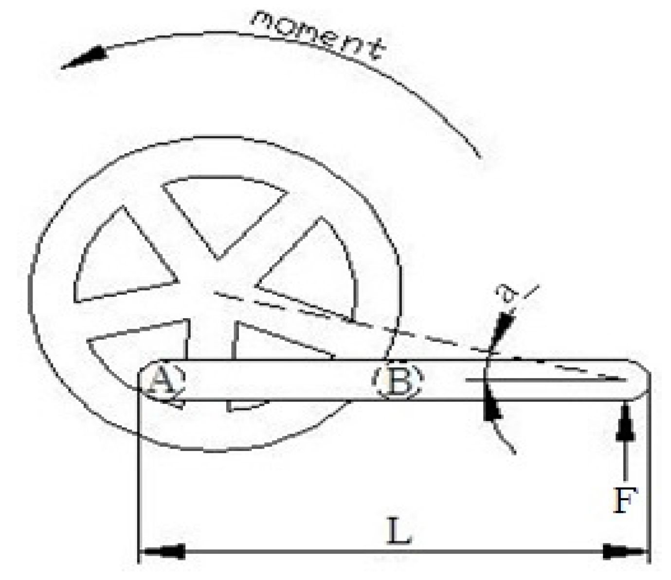
- Capability stress of bend torque (M): 100 (N-m);
- (4)
- ANSYS [3] numerical analysis setting:
- (A)
- Element type: SOLID187;
- (B)
- Node No.:45885; and
- (C)
- Meshing method: Free mesh (tetrahedron).
4. Concluding Remarks
Author Contributions
Funding
Institutional Review Board Statement
Informed Consent Statement
Data Availability Statement
Acknowledgments
Conflicts of Interest
References
- Lin, M.C.; Wang, C.T.; Fu, Y.D. Trapezoid Wrench. Patent No. M474597; Taipei, Taiwan, 21 March 2014. [Google Scholar]
- Montgomery, D.C. Design and Analysis of Experiment, 5th ed.; John Wiley & Sons: New York, NY, USA, 2001. [Google Scholar]
- Swanson Analysis System Inc. Ansys User’s Manual, Revision 14.5; Element (Software Manual); Swanson Analysis System Inc.: Canonsburg, PA, USA, 2013. [Google Scholar]


| Factor | Factor Code | Level 1 | Level 2 | Level 3 |
|---|---|---|---|---|
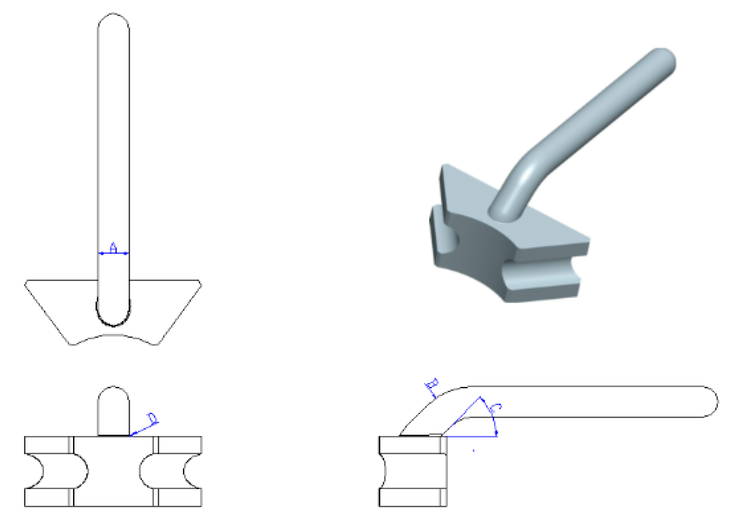
| Outer diameter | A | 20 mm | 22 mm | 24 mm |
| Bend radius | B | 33 mm | 35 mm | 37 mm |
| Angle | C | 45° | 50° | 55° |
| Connected fillet | D | 0.25 mm | 0.5 mm | 0.75 mm |
| Factor No. | A (mm) | B (mm) | C (Degree) | D (mm) | Von Mises Stress (MPa) | S/N Ratio |
|---|---|---|---|---|---|---|
| 1 | 20 | 30 | 45 | 0.25 | 430.54 | −52.6803 |
| 2 | 20 | 35 | 50 | 0.50 | 307.57 | −49.7589 |
| 3 | 20 | 40 | 55 | 0.75 | 230.68 | −47.2602 |
| 4 | 22 | 30 | 50 | 0.75 | 199.93 | −46.0176 |
| 5 | 22 | 35 | 55 | 0.25 | 286.21 | −49.1337 |
| 6 | 22 | 40 | 45 | 0.50 | 253.23 | −48.0703 |
| 7 | 24 | 30 | 55 | 0.50 | 194.20 | −45.7650 |
| 8 | 24 | 35 | 45 | 0.75 | 146.87 | −43.3387 |
| 9 | 24 | 40 | 50 | 0.25 | 285.98 | −49.1267 |
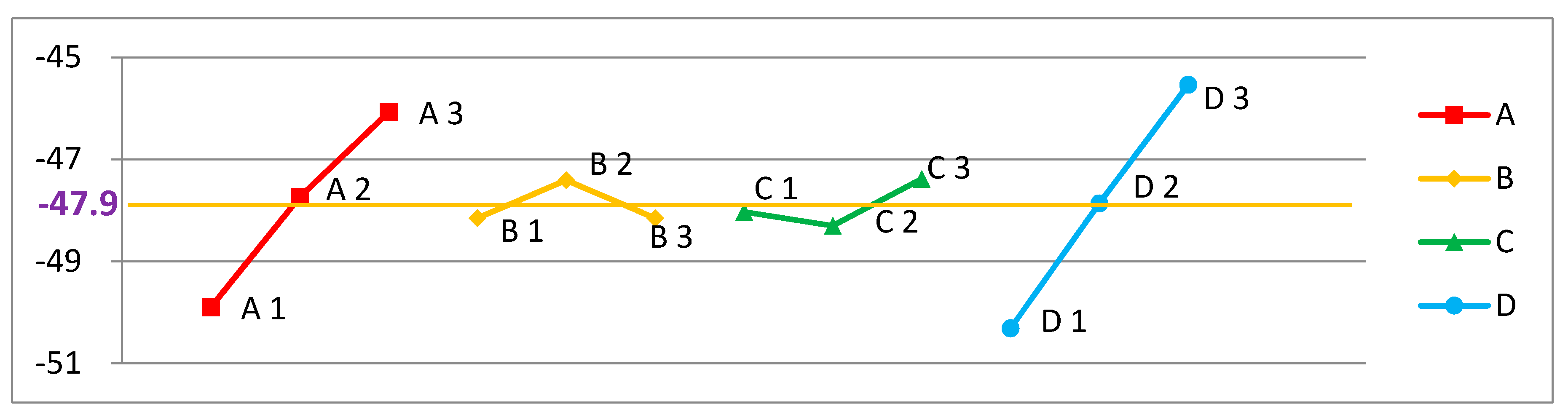
| Factor | Factor Code | Best Results |
|---|---|---|
| Outer diameter | A | 24 mm |
| Bend radius | B | 35 mm |
| Angle | C | 55° |
| Connected fillet | D | 0.75 mm |
Publisher’s Note: MDPI stays neutral with regard to jurisdictional claims in published maps and institutional affiliations. |
© 2021 by the authors. Licensee MDPI, Basel, Switzerland. This article is an open access article distributed under the terms and conditions of the Creative Commons Attribution (CC BY) license (https://creativecommons.org/licenses/by/4.0/).
Share and Cite
Lin, M.-C.; Ho, T.-H. Design Study for a New Spanner. Appl. Sci. 2021, 11, 8878. https://doi.org/10.3390/app11198878
Lin M-C, Ho T-H. Design Study for a New Spanner. Applied Sciences. 2021; 11(19):8878. https://doi.org/10.3390/app11198878
Chicago/Turabian StyleLin, Ming-Che, and Tsung-Han Ho. 2021. "Design Study for a New Spanner" Applied Sciences 11, no. 19: 8878. https://doi.org/10.3390/app11198878
APA StyleLin, M.-C., & Ho, T.-H. (2021). Design Study for a New Spanner. Applied Sciences, 11(19), 8878. https://doi.org/10.3390/app11198878