Abstract
The effect of correlated color temperature (CCT) on the thermal performance of light emitting diode (LED) filament in flip-chip packaging was investigated in detail. Two filaments with different lengths were selected as the research object, and the thermal resistance of filaments under three CCT (2200 K, 2400 K, 2700 K) were studied. The optical properties and thermal parameters of the two groups of filaments were measured, and the results were analyzed combined with the color coordinate. The experimental results show that thermal properties of LED filaments is closely related to CCT. Under constant current condition, junction temperature decreases with the increase of color difference. With the change of phosphor glue and phosphorus powder ratio, the color temperature of LED filament also changes. In the filaments with the same chip structure and packaging mechanism, the higher the proportion of red phosphorescent powder, the worse the heat dissipation performance of the filament. These results show that in the design and manufacture of LED filament, it is helpful to control the CCT of LED filament under the premise of meeting the use requirements.
1. Introduction
Light-emitting diodes (LED), an ultramodern cold light source, have the advantages of energy saving, environmental protection, long life and stable performance. Therefore, it is widely used in daily lighting, animal and plant culture and even liquid crystal display [1,2,3,4]. However, when using LEDs as everyday lighting materials, there are many aspects to pay attention to. Efficiency and color characteristics must be considered when designing LED light sources [5,6]. The color of the light emitted by the LED filament is not exactly the same as the color of the light emitted by the black body at various temperatures, so the concept of “correlated color temperature” is used in LED. T Chen et al. concluded that 80% of the energy input to the LED is dissipated as heat [7]. Therefore, the key to LED development is how to process heat management efficiently.
LED filament is the core component of LED light bulb. Different packaging methods, packaging substrate materials, phosphor ratio, chip size and substrate have a crucial impact on the optical properties and heat dissipation of LED filaments [8,9,10,11]. Ref. [12] conducted experimental and numerical analyses of LED modules using aluminum substrates and anisotropic graphite composites with a stationary heat source and ratio of length to diameter of substrate. The lateral temperature distribution of graphite substrate is more uniform under the same input power. Meanwhile, they concluded that the thermal conductivity of substrate has a great influence on high power LED. Christensen et al. designed a compact and high-power LED arrays considering the packaging methods, thermal interface materials and electrical tracer layer, which significantly reduces the temperatures and effectively extends the service life [13]. Wang J C et al. studied thermal performance experiments on LED steam chamber substrate, copper substrate and aluminum substrate. When the input power is fixed at 6 W, the experimental thermal resistance values of copper substrate and steam chamber substrate are 0.41 °C/W and 0.38 °C/W, respectively. The optical power of steam chamber substrate is 5% greater than that of aluminum substrate [14]. Chien-Ping Wang et al. conducted the effect of the thermal resistance inflection point of dual chips caused by the thermal boundary on the PN junction temperature [15]. The larger the distance between the plate and the edge, the higher the temperature of the PN junction, and the greater the influence on heat dissipation. This conclusion is consistent in different current magnitudes. However, few teams of researchers have conducted a series of theoretical studies that directly correlate CCT with the thermal properties of LED filaments through phosphors.
Electric energy is not only converted into heat energy, but also more than 20% of the energy is converted into light in the LED filament [16,17]. Therefore, the photoelectric performance should also be considered as an important factor when studying the influence of color temperature on the thermal performance of LED filament structure.
The purpose of this paper is to study the influence of color temperature on the thermal properties of LED filaments. Through the experimental measurement of LED filaments with the same substrate, chip and package structure but different color temperature, the relationship between color temperature and the thermal performance of LED filaments is studied by utilizing light efficiency, light flux, the junction temperature and thermal resistance.
2. Sample Preparation
The experiment needs to prepare two specifications of LED filaments. The two kinds of filament chips are Blu-ray flip chips produced by Ju Ho Company. The main wavelength is 450–455 nm, and the forward voltage is 3.1 to 3.2 V. The length of the 175-mm filament is 175 × 1.2 × 0.38 permeable aluminum substrate comprised of 100 lip-chips connected in series at equal intervals. The length of the 255-mm filament is 255 × 1.2 × 0.38 permeable aluminum substrate comprised of 144 lip-chips connected in series at equal intervals. The two ends of the substrate were welded with a metal iron and plated with nickel. The lip-chips and substrates were heated and soldered in a vacuum reflow furnace, waiting for the packaging.
Next, the glue was mixed and industrial art was dispensed. The material is as follows: Epoxy resin AB glue (6037-51, Guangdong Jieguo Company, Guangzhou, China); Yellow-green Ga3Al2(SiO4)3 phosphors (YH-Y530L, from Hangzhou Yingke Company, Hangzhou, China); Red phosphors (SSDR625, from Yantai Bright Company, Yantai, China); and Yellow phosphors (SSDR650, from Yantai Bright Company, Yantai, China). The mass ratio of phosphors to obtain different CCT is shown in Table 1.

Table 1.
Phosphor and glue ratio.
After mixing the glue, the prepared materials are placed into the vacuum defoaming mixer and stirred fully. Finally, the LED filaments are packaged by dispensing. The prepared LED filaments and bulbs are shown in Figure 1. The finished Electroluminescence (EL) spectra of LED filaments are shown in Figure 2.
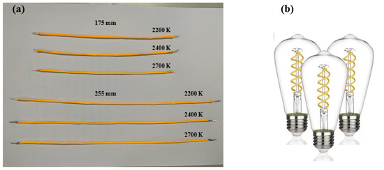
Figure 1.
(a) Two filaments with different lengths (175 mm and 255 mm) under three color temperatures (2200 K, 2400 K, 2700 K); (b) LED filament bulb.
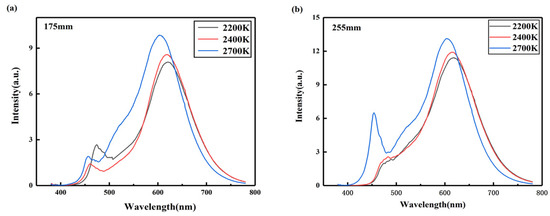
Figure 2.
Electroluminescence spectra of (a) 175 mm LED filament and (b) 255 mm LED filament with CCTs of 2200 K, 2400 K and 2700 K.
3. Experimental Method
3.1. Optical Experimental Measurement
The optical properties such as luminous flux and luminous efficiency of the LED filament were measured by integrating sphere (SIS-3 _ 2.0 m _ R98 _ Φ700 mm) of EVERFINE Yuan fang Company. In order to reduce the experimental error, each sample is measured three times to take the average value of each measurement results as the final analysis data. The 175-mm LED filament was measured under 15 mA constant current source, and the 255-mm LED filament was measured under 45 mA constant current source. The experimental data were recorded when the filament reached steady state 30 min after lighting. The results are shown in Figure 3.
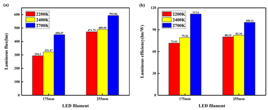
Figure 3.
(a) Luminous flux of three CCTs LED filaments after steady state; (b) Luminous efficiency of three CCTs LED filaments after steady state.
3.2. Thermal Experimental Measurement
The average junction temperature and thermal resistance of LED filament were obtained by the junction temperature tester LED-T300B (Manufactured by Shanghai Environmental Equipment Corp, Shanghai, China). In the experiment, three thermocouples are connected on the surface of each filament. In order to reduce the experimental error, and take the average value of the data obtained by the three thermocouples, represents the junction temperature, and represents the temperature of the thermocouple glue point. The experimental platform temperature was 25 °C, and the experimental data were recorded after the filament was lighted for 30 min to reach the steady state. The stable power of the 175-mm filament was 4.331 W and the 255-mm filament was 5.988 W. The experimental results are shown in Figure 4.
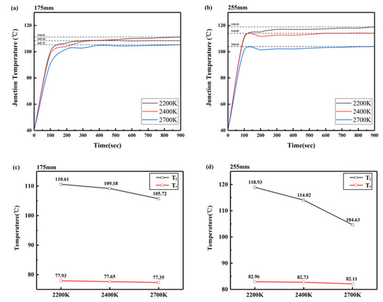
Figure 4.
(a) Junction temperature curve (175 mm); (b) Junction temperature curve (255 mm); (c) The diagram of junction temperature and glue point temperature at stable state (175 mm); (d) The diagram of junction temperature and glue point temperature at stable state (255 mm).
4. Results and Discussion
Because human eyes have different relative visual sensitivity for light of different wavelengths, for various SPD (spectral power density), the luminous flux will be the following:
where K is the maximum value of the spectral luminous efficacy, equal to 683 lm/W; is the spectral density of the radiant flux; λ is the wavelength of light; V(λ) is the standard spectral luminous efficacy function specified by the Commission International de I’E clearage, which refers to the ratio of two radiation fluxes, λm and λ, at the same wavelength of visual brightness perceived by human eyes under specific photometric conditions.
The light efficiency characterizes the ratio of the luminous flux to the electric power consumed. Different sources emit the same luminous flux. The less power consumed, the higher the luminous efficiency. The higher the light efficiency, the better the LED filament’s ability to convert electrical energy into light.
Two lengths of LED filament were used as the results for analysis. After the filament emits light for 30 min to reach a steady state, the power demands of 2200 K, 2400 K and 2700 K are 4.107 W, 4.056 W and 4.036 W, respectively. It can be seen from Figure 2 that under the same package structure, the luminous efficiency of the 2700 K filament is 111.6 lm/W, which is 35.8 % and 28.9 % higher than that of the 2200 K and 2400 K filaments, respectively. As a comparison group of the 255-mm LED filaments, after reaching a steady state, the powers of 2200 K, 2400 K and 2700 K were 5.886 W, 5.94 W and 5.922 W, respectively. The luminous efficiency of the 2700 K filament is 100.11 lm/W, which is 19.9% and 17.8% higher than that of 2200 K and 2400 K filaments, respectively. In terms of the light efficiency, the 2700 K filament is significantly improved compared to the other two filaments with lower color temperature. According to the conservation of energy, the heat loss of the 2700 K filament is much lower than that of the other two CCT filaments. That is to say, the heat loss of the 2700 K filament is significantly lower than that of the other two filaments.
Figure 3 shows the difference in thermal performance of the filament at different color temperatures. As shown in Figure 4a,c, the temperature of the thermocouple glue point of filaments with different color temperatures varies within 0.6 °C, and the change range is not large. It shows that when the current is constant, the thermocouple glue point temperature has little relationship with the color temperature. As shown in Figure 4d, the thermocouple glue point temperature mainly depends on the material of the thermocouple itself and the passing current. As shown in Figure 4a,b, the junction temperature of the filaments of the two lengths reaches a steady state at about 300 s, and the junction temperature varies greatly. In the steady state, the junction temperature decreases with the increase of the color temperature. In the 175-mm LED filament result, the filament junction temperature decreased by 1.43 °C (2400 K) and 4.89 °C (2200 K), respectively. The CCT of the 175-mm LED filament is 2700 K, and the junction temperature is 105.72 °C in the steady state. The maximum temperature difference is 4.89 °C, which is 4.6% lower than the filament color temperature of 2200 K. The junction temperature of the 255-mm filament with a color temperature of 2700 K is 104.63 °C, and the maximum temperature difference is 14.3 °C, which is 13.7 % lower than that of the filament with a color temperature of 2200 K.
Thermal resistance is one of the parameters that can best measure the heat dissipation of LED devices. It represents the ratio between the temperature difference between the two ends of the object and the stable power of the heat source when the heat flow is transferred along the heat sink. The calculation method is shown in Formula (2):
where represents the junction temperature, represents the temperature of the thermocouple glue point, and the unit of thermal resistance is °C/W. When the filament is made, the surface of the filament is fully covered by fluorescent glue and the contact surface with the chip is well sealed, so there is no contact thermal resistance due to the thermal convection of the interface itself. Formula (2) can be directly used to calculate the thermal resistance of the LED. The calculation result of thermal resistance is shown in Figure 5. Under the same lining condition, the thermal resistance change law is similar to the junction temperature, and it decreases for the filaments built for higher CCT. It shows that the heat dissipation capacity of LED filaments is different under different CCT. The heat dissipation capacity of LED filaments with low CCT is poor, and the junction temperature and thermal resistance are higher than those with high CCT.
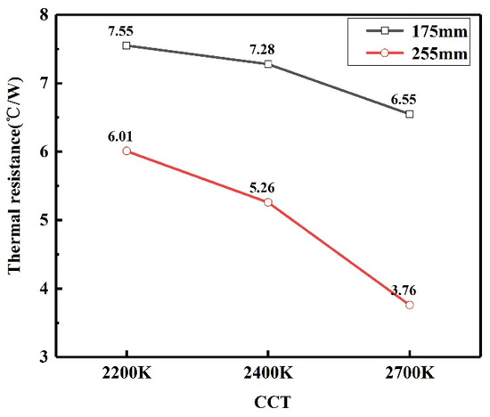
Figure 5.
Thermal resistance curves of filaments of two different lengths (175 mm, 255 mm) at different color temperatures (2200 K, 2400 K, 2700 K).
The color temperature of the LED filament is directly related to the phosphor content of each color added when preparing the filament. In order to better analyze the relationship between the content of each color powder of the phosphor and the thermal performance, the color content of the experimental sample filaments measured by the EVERFINE integrating sphere is shown in Table 2, and the color coordinates of the filaments with different color temperatures are shown in Figure 5. When the input light interacts with the phosphor, there is a complicated process of electricity, heat, light energy conversion and light tracking. According to the law of the conservation of energy, when short-wavelength light excites the phosphor, the black body is heated, part of the energy is converted into long-wavelength light and the other part is dissipated in the form of heat. It can be seen from Table 2 that the higher the color temperature of the filament, the lower the red powder content and the higher the green powder content. The red phosphor CASN: Eu2+ has a strong absorption and blocking effect, which reduces the absorption of the green phosphor LuAG: Ce3+ green luminescence, so the higher the proportion of the red phosphor, the greater the heat loss. Figure 6 shows the offset of the color coordinates for different color temperatures. The lower the color temperature, the stronger the absorption of the red phosphor CASN: Eu2+, and the overall color coordinate shifts to the red spectrum in the lower right corner. When energy conversion is performed, the heat absorption is significantly increased, which leads to an increase in junction temperature and thermal resistance and an increase in heat loss.
Table 2.
Proportion of phosphor color.
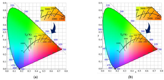
Figure 6.
Chromaticity coordinate: (a) 175-mm filament; (b) 255-mm filament.
5. Conclusions
In this paper, the effect of different phosphor ratios (for different CCTs) on the thermal performance of LED filaments packaged with dispensing was studied. Three kinds of phosphors ratio for different CCT (2200 K, 2400 K and 2700 K) were used to package LED filaments of two chip lengths. The average junction temperature, thermal resistance, light efficiency, phosphor color proportion and chromatic coordinates of the two groups of filaments were measured and compared. The light efficiency of the two filaments increased with the increase of color temperature, and the heat loss decreased significantly with the increase of color temperature. In the case of a constant input of electric current, the higher the CCT, the lower the average junction temperature, the smaller thermal resistance and the better the heat dissipation effect of the filament. Because different phosphor powder ratios lead to different color temperatures, the chromatic coordinate values of the two groups of filaments are further measured. With the absorption of red phosphor, CASN: Eu2+ becomes weak, and the thermal energy absorption of the LED filament weakens when it works stably. The heat dissipation effect of the LED filament is improved to some extent. The results have certain guiding significance for dispensing encapsulated LED filaments in balancing luminous efficiency and color temperature.
Author Contributions
Conceptualization, H.J. and J.S.; methodology, J.S.; software, C.F.; validation, H.G., X.Y. and X.S.; formal analysis, H.J.; investigation, Y.Z.; resources, X.Y.; data curation, H.J.; writing—original draft preparation, H.J.; writing—review and editing, H.J.; visualization, Z.Z.; supervision, J.S.; project administration, Y.Z.; funding acquisition, H.J. All authors have read and agreed to the published version of the manuscript.
Funding
This research received no external funding.
Institutional Review Board Statement
Not applicable.
Informed Consent Statement
Not applicable.
Conflicts of Interest
The authors declare no conflict of interest.
References
- Wang, W.; Zou, J.; Zheng, Q.; Li, Y.; Yang, B.; Shi, M.; Li, Y.; Li, X.; Zhang, C.; Li, C.; et al. The Effect of Different Filament Arrangements on Thermal and Optical Performances of LED Bulbs. Appl. Sci. 2020, 10, 1373. [Google Scholar] [CrossRef] [Green Version]
- Jiang, N.; Zou, J.; Zheng, C.; Shi, M.; Li, W.; Liu, Y.; Guo, B.; Liu, J.; Liu, H.; Yin, X. Fabrication Process and Performance Analysis of CSP LED Filaments with a Stacked Package Design. Appl. Sci. 2018, 8, 1940. [Google Scholar] [CrossRef] [Green Version]
- Parbrook, P.J.; Corbett, B.; Han, J.; Seong, T.Y.; Amano, H. Micro-Light Emitting Diode: From Chips to Applications. Laser Photonics Rev. 2021, 15, 2000133. [Google Scholar] [CrossRef]
- Kang, M.S.; Lee, C.H.; Park, J.B.; Yoo, H.; Yi, G.C. Gallium nitride nanostructures for light-emitting diode applications. Nano Energy 2012, 391–400. [Google Scholar] [CrossRef]
- Chen, H.T.; Tan, S.C.; Hui, S. Nonlinear Dimming and Correlated Color Temperature Control of Bicolor White LED Systems. IEEE Trans. Power Electron. 2015, 30, 6934–6947. [Google Scholar] [CrossRef] [Green Version]
- Lee, A.T.; Chen, H.; Tan, S.C.; Hui, S.Y. Precise Dimming and Color Control of Light-Emitting Diode Systems based on Color Mixing. IEEE Trans. Power Electron. 2015, 31, 65–80. [Google Scholar] [CrossRef] [Green Version]
- Cheng, T.; Luo, X.; Huang, S.; Liu, S. Thermal analysis and optimization of multiple LED packaging based on a general analytical solution. Proc. Electron. Compon. Technol. Conf. 2010, 49, 196–201. [Google Scholar] [CrossRef]
- Park, D.H.; Lee, D.B.; Seo, E.R.; Park, Y.J. A parametric study on heat dissipation from a LED-lamp. Appl. Therm. Eng. 2016, 108, 1261–1267. [Google Scholar] [CrossRef]
- Yang, X.; Guo, W.; Li, S.; Wang, J.; Sun, J. Influence of optical power calculation on LED thermal resistance test. In Proceedings of the China International Forum on Solid State Lighting: International Forum on Wide Bandgap Semiconductors China, Beijing, China, 1–3 November 2017; pp. 28–31. [Google Scholar]
- Lee, T.Y.; Kang, M.S.; Yoo, S.; Kim, Y.H.; Kim, M.S. Effect of (Ni, Au)3Sn4 growth on the thermal resistance of Au-20 wt% Sn solder/ENIG joint in flip-chip LED packages. Jpn. J. Appl. Phys. 2020, 59, SLLE03. [Google Scholar] [CrossRef]
- Chen, Q.; He, C.; Gao, Y. Numerical Study on Natural Convection of High-power LED Street Lamp Heat Sink. Bandaoti Guangdian/Semicond. Optoelectronics. 2011, 32, 498–501. [Google Scholar]
- Yang, K.S.; Chung, C.H.; Tu, C.W.; Wong, C.C.; Yang, T.Y.; Lee, M.T. Thermal spreading resistance characteristics of a high-power light emitting diode module. Appl. Therm. Eng. 2014, 70, 361–368. [Google Scholar] [CrossRef]
- Christensen, A.; Graham, S. Thermal effects in packaging high power light emitting diode arrays. Appl. Therm. Eng. 2009, 29, 364–371. [Google Scholar] [CrossRef]
- Wang, J.C. Thermal investigations on LED vapor chamber-based plates. Lett. Heat Mass Transf. 2011, 38, 1206–1212. [Google Scholar] [CrossRef]
- Wang, C.P.; Kang, S.W.; Lin, K.M.; Chen, T.T.; Fu, H.K.; Chou, P.T. Analysis of Thermal Resistance Characteristics of Power LED Module. IEEE Trans. Electron Devices 2014, 61, 105–109. [Google Scholar] [CrossRef]
- Lin, A.D.; Yu, W.K.; Poon, S.Z.; Chen, C.Y.; Hsu, C.M. Study on Nitrogen-Doped Graphene Ink and Its Effects on the Heat Dissipation for the LED Lamps. Appl. Sci. 2020, 10, 2738. [Google Scholar] [CrossRef] [Green Version]
- Kuo, S.Y.; Chang, C.J.; Huang, Z.T.; Lu, T.C. Improvement of Light Extraction in Deep Ultraviolet GaN Light Emitting Diodes with Mesh P-Contacts. Appl. Sci. 2020, 10, 5783. [Google Scholar] [CrossRef]
Publisher’s Note: MDPI stays neutral with regard to jurisdictional claims in published maps and institutional affiliations. |
© 2021 by the authors. Licensee MDPI, Basel, Switzerland. This article is an open access article distributed under the terms and conditions of the Creative Commons Attribution (CC BY) license (https://creativecommons.org/licenses/by/4.0/).