Abstract
As a new technique, a fixed geogrid in a geogrid-reinforced and pile-supported (GRPS) embankments has been used to reduce the total and differential settlement. To investigate the load transfer mechanism of the fixed geogrid technique of a GRPS embankment, three discrete element method (DEM) models of pile-supported embankments were established, including an unreinforced embankment, a geogrid reinforced embankment, and a fixed geogrid reinforced embankment. The efficacy of the pile, the evolution law of the contact force chain and the axial force of the reinforcement, and the microscopic load-bearing structure of the soil were investigated. Numerical simulation results showed that the embankment self-weight and surcharge load were transferred to the pile through the soil arching and tensile membrane effect. The settlement could be effectively reduced via the addition of the reinforcement, and the fixed geogrid technique was more conducive to improving the load-bearing ratio of the pile than the traditional reinforcement technique. Compared with the traditional technique of a GRPS embankment, the fixed geogrid technique had a better effect on reducing the total and differential settlement. With the increase in the surcharge load and the settlement of the soft subsoil, the reinforcement transferred a greater load to the pile. The results also showed that the stress of the embankment fill was concentrated at the pile top in all three models. The GRPS embankment with a fixed geogrid technique had a lower soil stress concentration than the other two cases. The contact force chain and stress in the embankment also showed that the reformation of the microscopic load-bearing system of the embankment fill was the internal mechanism that caused the development of the soil arching and the redistribution of stress. Furthermore, the evolution of the fabric parameters in the arching area could reflect the evolution of the soil arching structure. In the fixed geogrid case, the proportion of the load transferred to the pile from the soil arching effect was reduced, and the vertical load transferred to the pile top by the tensile membrane effect accounted for 22–28% in this study. Under the combined effect of the tensile membrane and the soil arching, the efficacy of the pile could increase by 10%.
1. Introduction
Soft soil has low strength and high compressibility, and it takes a long time to consolidate under a surcharge load due to its low permeability. Therefore, it is a great challenge to construct embankments on soft soil. Geogrid-reinforced pile-supported (GRPS) embankments have been widely used in highways, railways, airports, ports, and other infrastructure projects as a feasible soft-ground improvement technology [1,2,3,4,5,6]. The combination of a geogrid and piles for embankments could reduce the total and differential settlements of embankments. Existing studies indicate that the tensile membrane effect [7,8] of the reinforcement and the soil arching effect [9,10,11,12] are the key mechanisms of load transfer in GRPS embankments. Bhandari and Han [13] conducted a series of numerical studies on the geogrid–soil interaction mechanism under vertical cyclic loading and reported that when the geogrid was placed at a shallow depth, the deformation of the geogrid was significantly affected by the stiffness. There is a relationship between the laying position of the reinforcement and its tensile performance. Abusharar et al. [14] deduced a simplified formula for the pile–subsoil stress ratio of the GRPS embankment based on Hewlett’s planar semicircular soil arching model and reinforcement deformation arc model. Eskisar [3,12] used X-ray CT and visualization technology to observe the membrane action of the geogrid in the GRPS embankment and revealed the influence of a reinforcement layer on the load distribution of the embankment.
To improve the performance of GRPS embankments, a fixed geogrid technique was proposed for GRPS embankments [15,16]. As shown in Figure 1, compared with traditional GRPS embankments with unfixed geogrids, the fixed geogrid technique involves a mechanical connection between the reinforcement and the pile top so that the tensile effect of the reinforcement can transfer more of the embankment load to the pile. Although the fixed geogrid technique of a GRPS embankment was applied in engineering [16], the load transfer mechanism of this technique is not clear. Further research is needed to investigate the load transfer mechanism in the GRPS embankments using the fixed geogrid technique.
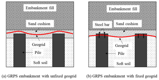
Figure 1.
GRPS embankment with a fixed and an unfixed geogrid.
The discrete element method (DEM), as a discontinuous numerical simulation method, was widely used to investigate the load transfer mechanism of the pile-supported embankments [17,18]. Le Hello et al. [8] suggested that the continuum-based numerical model cannot fully reflect the stress transfer mechanism of the embankment with granular fill, and established a three-dimensional discrete element numerical model of a GRPS embankment, which verified the rationality of the discrete element numerical method. Jenck et al. [17] used the FEM and the DEM to simulate a laboratory two-dimensional model test of a pile-supported embankment and reported that the discrete element method could better predict the load transfer and deformation of the embankment.
In this study, based on the two-dimensional laboratory model tests conducted by Jenck et al. [19], three DEM models of pile-supported embankments were established to study the load transfer mechanism of GRPS embankments. The efficacy of the pile, the evolution law of the contact force chain, the axial force of the reinforcement, and the microscopic load-bearing structure of the soil were investigated. The research results are helpful for understanding the load transfer mechanism of GRPS embankments using the fixed geogrid technique.
2. Establishment and Calibration of DEM Model
Two-dimensional DEM software, namely, the particle flow code (PFC2D), was used to build the numerical model in this study. The establishment of the DEM model was based on the two-dimensional laboratory model tests conducted by Jenck et al. [19]. In the laboratory model tests, analogical soil (steel rods) was used as embankment fill, and foam material was used as the subsoil between the piles. Well-calibrated micromechanical parameters were the basis for the numerical model to reproduce the mechanical response of the test material.
The contact constitutive model in the PFC involved in this study included a linear model and a linear parallel bond model. Among them, the linear model was used to simulate the linear elastic friction behavior of grain particles. The linear contact force acts on a vanishingly small area, so only one force is transmitted. The linear parallel bond contact provides the mechanical behavior of the finite-size cement-like material deposited between the two contact pieces and establishes an interaction between the two particles. A linear parallel bond can transfer forces and moments between particles. When the parallel bond fails (the maximum stress or moment exceeds its failure strength), the linear parallel bond model degenerates into a linear model. In this study, the linear model was used to simulate the contact between the embankment fill and the subsoil between the piles, and the linear parallel bonded model was used to reproduce the mechanical response of the reinforcement. The micromechanical properties of the test materials were back-calculated through simulation tests with clear boundary conditions. The size and macrophysical properties of the test materials in the DEM models were consistent with the laboratory models. In addition, based on the model tests, the geogrid was adopted in the numerical model to compare the load transfer mechanisms of GRPS embankments with a fixed geogrid and an unfixed geogrid in this study.
2.1. Embankment Backfill Modeling
In the laboratory models, three types of metal rods with different diameters were uniformly mixed according to the same volume ratio (1:1:1) as the embankment fill material. The length of the round steel rods was 60 mm and the diameters were 3, 4, and 5 mm, respectively. The biaxial rods were widely adopted to study the mechanical behavior of geotechnical materials in two-dimensional physical models [7]. Biaxial simulation tests, holding the same size (width × height = 200 mm × 220 mm) with the laboratory biaxial tests, were used to invert the micromechanical parameters based on the macromechanical response in this study. The embankment fill was simulated using unbonded two-dimensional disk particles. In the biaxial simulation tests, the numerical specimen was established with a porosity of 0.145. The confining pressures of 20, 30, and 40 kPa were applied through the wall servo mechanism. After the unbalanced force in the model dissipated to a stable state (<1 × 10⁻⁵), biaxial loading at a constant velocity (vw) of 1 × 10⁻⁶ m/s was applied to the upper and lower walls.
Figure 2 shows the comparison of the results between the simulation and the laboratory tests. The curve of deviatoric stress versus axial strain of the numerical simulation was in good agreement with the experimental results. The friction angle ϕ of the assembly was calculated as follows:
where σ1 and σ3 represent the maximum and minimum principal stresses, respectively. According to the laboratory model tests [19], the friction angle of the assembly in the numerical model was 24°. It is noteworthy that the friction angle of particles under the two-dimensional arrangement obtained in this way was generally lower than that of natural granular materials, and this phenomenon was reported in many laboratory tests [19,20,21].
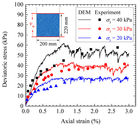
Figure 2.
Comparison of the numerical and experimental results for the biaxial tests.
2.2. Modeling of the Subsoil between Piles
Consistent with the selected model tests by Jenck et al. [19], the microparameters of the subsoil between the piles were calibrated using a compression test for a specimen with a width of 550 mm and a height of 150 mm. In this study, the subsoil was simulated by disk particles with a diameter of 3–5 mm that were uniformly distributed. Similarly, the unbonded linear contact model was used for the interparticle contact of the subsoil between the piles. The compression specimen was generated by the layered compression method [18], and the porosity of the initial specimen was controlled at 0.14 until the model reached a stable state. Same as the laboratory test, the compression loading rate vc of the top wall was 10−6 m/s.
The comparison of vertical stress versus settlement between the DEM simulation and the physical test is shown in Figure 3. In the laboratory test, the growth rate of the settlement of the subsoil between the piles increased with increasing surcharge load, which indicated the yielding of the soil during compression. It is noteworthy that the unbonded particles in this study were used to simulate the subsoil between the piles, while the foam was used in the physical model. Although the non-linear change in the strength of the foam material was not reflected in the numerical model, the load in the numerical model was similar to the laboratory compression test within the settlement range of 0–30 mm. In the laboratory model tests, the settlement of the soil between the piles was always less than 30 mm, as reported by Jenck et al. [19]. It should be noted that the settlement of the subsoil between the piles is important for the development of the soil arching effect. The subsoil between the piles in the physical model was simulated using foam, and the purpose of the unbonded assembly in the numerical simulation was to reproduce the compression–settlement characteristics. Within the tolerance range (0–30 mm), the compression–settlement characteristics of the numerical model and the physical model were essentially consistent.
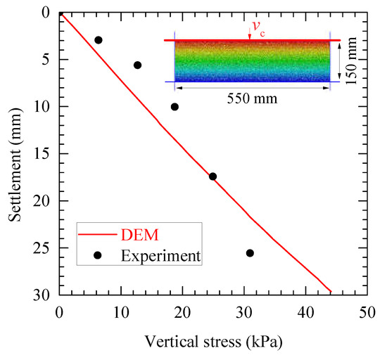
Figure 3.
Comparison between the numerical and experimental results for the compression loading tests.
2.3. Geogrid Modeling
Reinforcement was not considered in the laboratory pile-supported embankments model by Jenck et al. [19]. To study the fixed geogrid technique, a numerical geogrid tensile test was carried out for calibration. The reinforcement was produced using the regular arrangement of particles with a diameter of 2 mm. For the contact between the particles, parallel bonding that could bear the tensile stress and the bending moment was selected to reproduce the tensile mechanical response of the geogrid. A numerical tensile specimen with a length of 100 mm was established. The particle at one end of the specimen was fixed, while a tensile rate (vt) of 20 mm/min was applied to the particle at the other end. As shown in Figure 4, the DEM tensile results were in reasonable agreement with the laboratory tensile test.
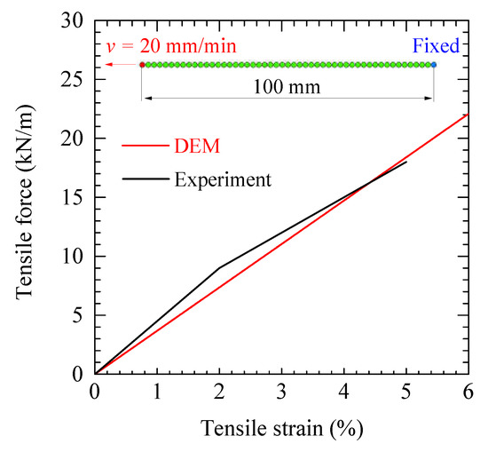
Figure 4.
Comparison between the numerical and experimental results for the geogrid tensile tests.
2.4. Numerical Simulation Procedure for the GRPS Embankments
Based on the calibration tests, the calibrated micromechanical parameters of each material are shown in Table 1. The servo loading mechanism was defined for the top wall to control the surcharge load in stages on the embankment surface, with each load increment being 10 kPa.

Table 1.
Micromechanical parameters for the DEM models (Part of the data was reported by Lai et al. [18]).
Similar to the simplified numerical method used by Han et al. [9] and Lai et al. [18], to balance the calculation efficiency and the number of particles, according to the symmetry of the GRPS embankment model, half of the laboratory model was considered for the numerical model, as shown in Figure 5. A model box with a width of 420 mm and a height of 850 mm was built using the walls. The height of the pile in the numerical model was 150 mm and the width was 50 mm (the half-width of the physical model). The clear spacing between piles was 320 mm. The model building process was as follows:
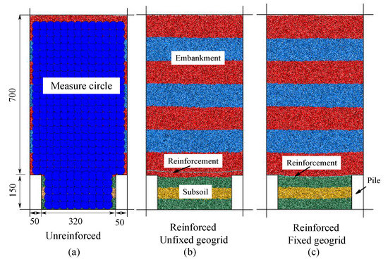
Figure 5.
DEM models of the embankment arrangements (unit: mm).
(1) The model boundary and piles were simulated using walls, and then the subsoil between the piles with an initial porosity of 0.14 was generated in three layers (each layer with a thickness of 50 mm) and auxiliary walls were created to compact the subsoil. Then, the calculation was performed until the unbalanced force dissipated to a tolerable level and the auxiliary wall could be removed.
(2) The geogrid was generated and different bonding properties at the ends were set. In the fixed geogrid model, both ends of the reinforcement were fixed to the top of each pile to prevent horizontal and vertical displacements. In the unfixed geogrid model, a 20 mm thick cushion of granular material was created, and then the reinforcement was placed. The horizontal displacement of the ends of the geogrid was fixed but could move freely in the vertical direction.
(3) Embankment backfill with an initial porosity of 0.14 was generated and compacted in layers. Same as the physical model, the thickness of each layer was 100 mm.
(4) Forty-five measure circles with a diameter of 20 mm were created between the two piles to monitor the stress distribution of the subsoil. The distance between the centers of any two adjacent measure circles was 60 mm. Similarly, the upper embankment filling area was arranged with 286 measure circles, as shown in Figure 5a. Then the particle displacement was cleared and the recording parameters were set. The servo loading mechanism was defined for the top wall to control the surcharge load in stages on the embankment surface, with each load increment being 10 kPa.
3. Results and Discussions
3.1. Settlements and Particle Displacements
Under the surcharge load on the embankment surface, the difference in stiffness between the pile and the subsoil causes the differential settlement. In this study, the piles were considered to be rigid walls, and the differential settlement between the pile and the subsoil was entirely contributed by the compression settlement of the subsoil. Figure 6 shows the displacement amplitude of the particles under the surcharge load of 100 kPa. For the three numerical simulations, the settlement on the top of the embankment was the largest. The results showed that the geogrid layer could reduce the total settlement on the embankment surface settlement. Figure 7 shows the settlement of the subsoil under different surcharge loads to identify the influence of reinforcement on the settlement characteristics of the subsoil. Compared with the unreinforced embankment, the effect of the reinforcement on reducing the settlement of the subsoil was obvious. The maximum settlement value of the subsoil was reduced by 14%, compared to that without reinforcement. For the fixed geogrid and unfixed geogrid conditions, the settlement at the centerline of the subsoil was almost the same, while the settlement of the subsoil that was closer to the pile in the fixed geogrid case was smaller. This effect was more pronounced with increasing surcharge load. In the model with the unfixed geogrid, the settlements of the subsoil particles near the pile (distance from 50 to 150 mm) ranged from 16.79 to 20.14 mm under the surcharge load of 500 kPa, while the corresponding range was 6.71–16.79 mm in the model with the fixed geogrid. This reflects the advantages of the fixed geogrid technique in controlling the differential settlement between the piles and subsoil.
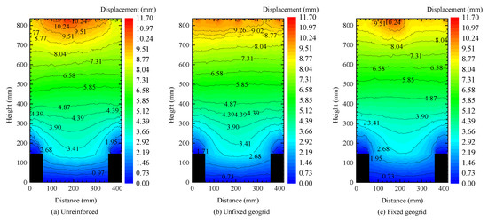
Figure 6.
Comparison of the particle displacements of the embankments (surcharge load = 100 kPa).
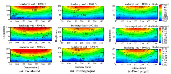
Figure 7.
Comparison of the particle displacements of subsoil between the piles.
3.2. Stresses in the Embankment and Subsoil
The development mechanism of stress in the embankment can reflect the load transfer process. The redistribution of stress within the embankment caused by the relative movement of soil particles under a surcharge load can reflect the formation process of soil arching. Based on the magnitude of the stress in the embankment and the rotation of the principal stress direction, the formation and development of the soil arching effect can be analyzed. In PFC, the stress of the part of interest in the model can be monitored by arranging the measure circle. The principal direction θ of the stress can be calculated as follows:
where σxx, σxy, and σyy represent the horizontal, tangential, and vertical stresses respectively.
Figure 8a–c shows the measured stress tensor under the self-weight load of the embankment. The magnitudes of stress were relatively uniform at the same elevation. This indicated that the soil arching had not formed yet at this stage because the relative displacement between the pile and subsoil under the self-weight was very small. In all three models, the internal stress of the embankment gradually increased with the increase in depth. In the unreinforced model, the load on the pile top and the subsoil were basically at the same level. In the reinforced embankment, even if no surcharge load was applied, the role of the reinforcement was initially manifested. The geogrid underwent a small deformation under the self-weight of the embankment and became in tension, which generated the membrane effect. The stresses of the subsoil in the reinforced models were smaller than that in the unreinforced model. In contrast, the reinforcement transferred part of the stress to the pile through the tensile membrane effect, and the soil stress around the reinforcement and the pile top was significantly increased. In addition, the stress distribution around the reinforcement in the fixed geogrid case was more even. The principal direction of the stress above the pile top and the geogrid material was mainly vertical.
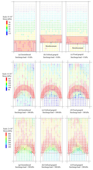
Figure 8.
Comparison of the stress tensors in the three cases.
Figure 8d–j shows the stress distribution in the embankment under the loads of 100 and 300 kPa. As the larger load was transferred to the embankment, the soil arching effect caused by the differential settlement between the pile and the subsoil gradually became more pronounced. The larger normal stress and tangential stress were concentrated above the soil arching area. The principal direction of normal stress was essentially consistent with the direction of arching, while the principal direction of tangential stress was perpendicular to the direction of soil arching. In all three models, the stress above the soil arching area was the same, and the main direction of the normal stress was vertical. The stress of the subsoil in the unreinforced case was greater than that in the reinforced cases. In the case of a fixed geogrid, the stress on the pile top included the load transferred from the reinforcement to the pile top.
3.3. Contact Force Chains and Orientations
The contact force chain in the particle system is the visual expression of the load transfer path. Figure 9 represents the contact force chain for the models under the surcharge load of 100 kPa. The dense area of the force chain represents a larger contact force, while the sparse area represents a smaller contact force. As shown in Figure 9, the strong force chain was mainly distributed above the soil arching, while the force chain below the soil arching was relatively weak, which is consistent with the stress distribution. In addition, in the fixed geogrid model, the tensile force distribution of the reinforcement was more uniform and the amplitude was larger than that of the unfixed geogrid model.
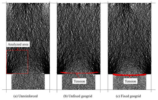
Figure 9.
Normal contact force chain in the models under a 100 kPa surcharge load.
The redistribution of stress in the particle system can be reflected by the evolution of the contact force. Rothenburg and Bathurst [22] proposed that the Fourier series approximation (FSA) method is suitable for the anisotropy analysis of granular materials. The normal contact force information in the area of interest is counted. Furthermore, in FSA fitting, the density distribution function of the normal contact force can be calculated as follows:
where f0 represents the average value of the normal contact force in the analyzed area, an is the FSA anisotropy coefficient of the normal contact force, and θ represents the principal anisotropy direction of the normal contact force in the area.
Taking into account the symmetry of the embankment and the soil arching effect, the analyzed area shown in Figure 9a was used to analyze the evolution of the contact force chain of the soil arching. As shown in Figure 10, the FSA fitting shows that the principal direction of the normal contact force in each model under 100 kPa was about 15°, and the strong force chain played a leading role in the deflection of the principal direction.
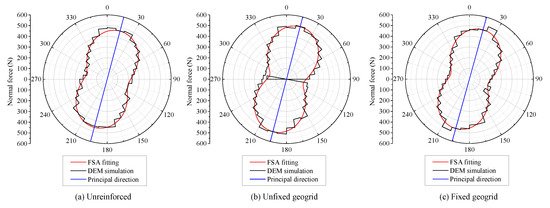
Figure 10.
FSA fitting results of the normal contact force in the arching area.
Figure 11 shows the evolution of the fabric parameters in the soil arching area of the three models under different surcharge loads. The fabric anisotropy coefficient an, which characterizes the degree of difference in the normal contact force for each contact direction, is more sensitive to changes caused by the rearrangement of particle positions and can more accurately reflect the subtle changes in the fabric of granular materials. The particle system changes the contact principal direction through the rotation and movement of the particles to form a stable microscopic load–transfer structure. As the surcharge load increases to the limit value of the microscopic load-bearing structure, a new microscopic load-bearing structure is rebuilt through the particles’ movements (rotation and displacement). The evolution of the anisotropy coefficient and the main direction of the contact force represents the process of microscopic load-bearing structure remodeling.
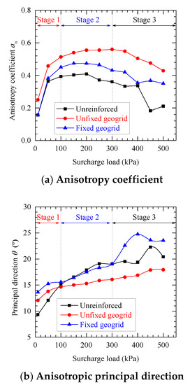
Figure 11.
Evolution of the fabric parameters in the soil arching area.
In Figure 11, the principal direction of the normal contact force and the anisotropy coefficient in the arching area both showed an increasing trend when the surcharge load was smaller than 100 kPa. This means that the movements of particles in the arching area of the reinforced and unreinforced models mainly occurred in the surcharge load range of 0–100 kPa (stage 1). The drastic changes of the anisotropy coefficient an and the principal direction θ of the normal contact force of the particles in the arched area indicated that the large-scale particle position rearrangement occurred in stage 1. With the increase in surcharge load, the fluctuation of the anisotropy coefficient of the normal contact force in stage 2 was smaller, while the principal direction of the normal contact force in the arched area was still increasing, indicating that the soil arching was in an essentially stable state. The decrease in an and the increase in θ in stage 3 corresponded to the reconstruction of the contact force chain, indicating that the soil particles in the arched area may have been mobilized in a large amount, which corresponded to the development of the difference in the soil between the piles. In the unreinforced model, the decrease in the anisotropy coefficient and the rotation angle in the principal direction of the normal contact force at the later stage (400–500 kPa) of loading indicated that the soil particles were disturbed to a greater extent. The principal direction of the normal contact force was inclined from the horizontal direction to the arching direction and gradually increased with the increase in the surcharge load. In general, the principal direction of the normal contact force in the analyzed area in the fixed geogrid case had the largest rotation angle. It is worth noting that the anisotropy coefficient of the normal contact force in the case of the unfixed geogrid was larger and the angle of the principal direction was smaller than that in the other two cases. This was probably because the laying position of the reinforcement was in the arching area in the unfixed case and the soil–reinforcement contact in this area contributed to the small inclination angle of the main direction and the large anisotropy coefficient.
3.4. Pile Efficacy
The efficacy E of the pile in the embankment proposed by Hewlett et al. [23] was used to evaluate the load transfer efficacy in the GRPS embankment. The soil arching structure transfers the load to the pile top. The load transfer efficacy E can be written as:
where Fp and W represent the vertical load shared by the pile and the load shared by the subsoil between the piles, respectively. Moreover, in the fixed geogrid model, the geogrid directly transfers the load through the bonding contact with the pile; therefore, the vertical load Fp that is shared by the pile can be divided into two parts: one is the load transferred from the embankment soil to the pile top through the soil arching, while the second is the vertical load transferred to the pile top through the tensile membrane effect. Therefore, the pile efficacy that is induced by the soil arching effect is recorded as E’ and can be calculated as follows:
where FR represents the vertical load transferred from the reinforcement to the pile top.
As Figure 12 represents, the efficacy E in the fixed geogrid embankment was always higher than those in the other models. The peak efficiency in the fixed geogrid, unfixed geogrid, and unreinforced cases were 66, 62, and 52% respectively. However, in the fixed geogrid model, the pile efficacy E’ (induced by soil arching) was between 28 and 40%, which was smaller than that of the unreinforced model. This indicates that the reinforcement that was mechanically connected to the pile top could reduce the bearing ratio of the soil arching. It is worth noting that during the surcharge load of 400–450 kPa, the load transfer efficiency in the unreinforced model dropped rapidly from 54 to 42%. This was attributed to the evolution of the soil arching structure and the reformation of the microscopic load-bearing structure, as discussed earlier. The changing trend of efficacy was the same as the changing trend of the fabric parameter an, which also showed that the microstructure reformation of the granular system was an important mechanism that affected the soil arching development and load transfer mechanism. The reinforcement could effectively improve the load transfer efficacy, which was consistent with the research of Lai et al. [22] and Han et al. [7]. In addition, this result also reflected that the fixed geogrid technique was beneficial to the efficacy of the piles in the GRPS embankment.
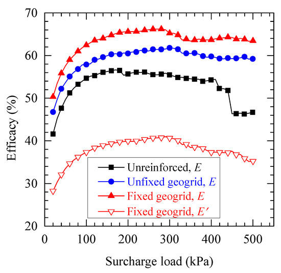
Figure 12.
The curves of efficacy E versus surcharge load.
To clarify the load transfer mechanism of the fixed geogrid technology, Figure 13 shows the load-bearing ratio of subsoil between piles, the soil arching effect, and the tensile membrane effect in the fixed geogrid model. Among them, the vertical load ratio that was transmitted by the reinforcement through the tensile membrane effect could be quantified as E’ - E, and the load-sharing ratio of the soil between the piles was 1 - E. The load transfer process could also be divided into three stages based on the previous mesofabric evolution: Stage 1 was the rapid development and shaping stage of soil arches. The proportion of the load shared by the soil between the piles gradually decreased from 50 to 37%, and the load transferred from the soil arching to the piles increased by 10%, while the proportion of the vertical load transferred by the reinforcement increased from 22 to 25%. Stage 2 was the gradual stabilization stage of the soil arching. The increase in the load transferred from the soil arching to the piles became smaller, accompanied by a further decrease in the soil load between the piles. The vertical load transferred by the reinforcement was stable at about 25%. Stage 3 was the soil arching reformation stage. The load-bearing ratio of the soil arching gradually decreased after reaching the peak value, and the tensile membrane effect of the reinforcement was more prominent. Under the surcharge load of 500 kPa, the vertical load that was transferred by the reinforcement increased to 28%, and the proportion of the soil between the piles increased further. This means that the soil arching reached the bearing limit, and the load transfer capacity of the reinforcement was gradually fully utilized.
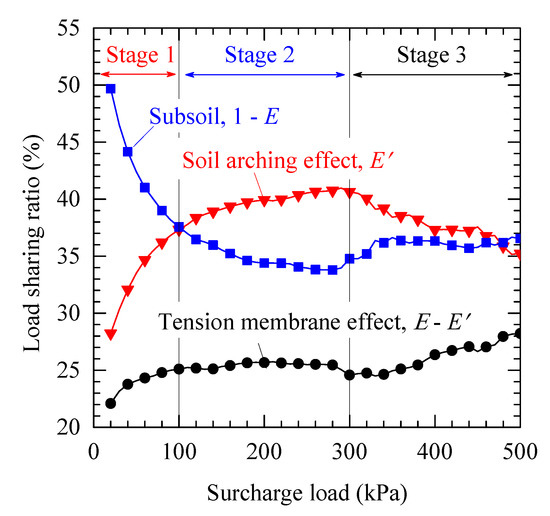
Figure 13.
Load-sharing ratio of the subsoil, soil arching effect, and tensile membrane effect in the fixed geogrid case.
3.5. Geogrid Tensions and Displacements
Figure 14 shows the tensile and vertical displacement of the geogrid in the fixed and unfixed geogrid cases. As expected, the geogrids sustained the catenary vertical deformation. The vertical deformation of the geogrids at the center of the subsoil in the fixed geogrid case was similar to that of the unfixed geogrid case, while the deformation of the geogrid near the pile was smaller than that of the unfixed geogrid case. Furthermore, the axial force of the reinforcement could be obtained by monitoring the normal force of the parallel bonds in the models. It can be seen that the tension in the reinforcement for the fixed geogrid case was more evenly distributed between the piles, and the axial force of the reinforcement was generally greater than that of the unfixed geogrid case (Figure 14b). With the increase in the surcharge load, the axial force of the reinforcement in the model of the fixed geogrid increased more obviously. Based on the previous analysis, the fixed geogrid allowed the reinforcement to directly transfer more of the upper load to the pile top, while the unfixed geogrid transmitted the load to the pile by interacting with the embankment filler (or sand cushion). Under the surcharge load of 500 kPa, the axial force of the fixed geogrid was about 10 kN larger than the axial force of the unfixed geogrid. This was also the main reason for the increase in efficacy. This indicated that the load transfer mechanism of the fixed geogrid case was different from that of the unfixed geogrid case.
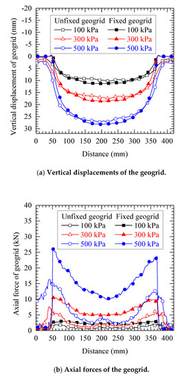
Figure 14.
Comparison of the geogrid displacements and the axial forces.
4. Conclusions
To investigate the load transfer mechanism of a GRPS embankment using the fixed geogrid technique, three discrete element method (DEM) models of pile-supported embankments were established, including an unreinforced embankment, a geogrid reinforced embankment, and a fixed geogrid reinforced embankment. The embankment settlement, relative displacement between the pile and the subsoil, soil stress, deformation of the reinforcement, and evolution of the contact force chain were analyzed. In addition, the embankment load transfer mechanism and efficacy of the pile were compared. The main conclusions are summarized as follows:
(1) The differential settlement between the pile and subsoil could be effectively controlled using geogrid reinforcement. Compared with the traditional technique of a GRPS embankment, the fixed geogrid technique had a better effect to reduce the total and differential settlement.
(2) In the three models, the stress of the embankment fill was concentrated at the pile top. The GRPS embankment with the fixed geogrid technique had less soil stress concentration than the other two cases, and the stress distribution along the embankment–soil interface was more uniform. The reinforcement directly transferred part of the load to the pile top, which was more conducive to the load transfer performance.
(3) The fabric parameters could reflect the evolution of the soil arching structure to a certain extent. The principal direction of the normal contact force chain in the arching area in the fixed geogrid case showed that the fixed geogrid technique could limit the displacement of the soil particles.
(4) The fixed geogrid technique could reduce the proportion of the load transferred to the pile from the soil arching effect, where the vertical load transferred to the pile top by the tensile membrane effect accounted for 22–28% in this study. Under the combined effect of the fixed reinforcement and the soil arching, the efficacy of the pile could increase by 10%.
(5) Compared with the other two cases, in the fixed geogrid model, the axial force of the reinforcement was greater, indicating that the higher tensile strength of the reinforcement was required to ensure the stable connection and the full utilization of the tension performance.
Author Contributions
Writing—original draft preparation, Y.J.; writing—review and editing, J.Z. and Y.Z.; Software, Y.J. and C.M.; All authors have read and agreed to the published version of the manuscript.
Funding
This research was funded by the National Key R&D Program of China (grant number: 2018YFB1600100) and the National Natural Science Foundation of China (no. 52178341, no. 52078392, and no. 51809191).
Institutional Review Board Statement
Not applicable.
Informed Consent Statement
Not applicable.
Data Availability Statement
Not applicable.
Acknowledgments
The authors gratefully acknowledge Hanjiang Lai for his technical help in the numerical modeling.
Conflicts of Interest
The authors declare no conflict of interest.
References
- Ariyarathne, P.; Liyanapathirana, D.S. Review of existing design methods for geosynthetic-reinforced pile-supported embankments. Soils Found. 2015, 55, 17–34. [Google Scholar] [CrossRef]
- Chen, R.P.; Xu, Z.Z.; Chen, Y.M.; Ling, D.S.; Zhu, B. Field Tests on Pile-Supported Embankments over Soft Ground. J. Geosynth. Ground Eng. 2010, 136, 777–785. [Google Scholar] [CrossRef]
- Eskişar, T.; Otani, J.; Hironaka, J. Visualization of soil arching on reinforced embankment with rigid pile foundation using X-ray CT. Geotext. Geomembranes 2012, 32, 44–54. [Google Scholar] [CrossRef]
- Feng, S.Y.; Xu, R.Q.; Yu, J.L. Field Monitoring of Geogrid-Reinforced and Pile-Supported Embankment at Bridge Approach. Int. J. Geosynth. Ground Eng. 2021, 7, 2. [Google Scholar] [CrossRef]
- Sandiford, R.E.; Law, S.; Roscoe, G. Application of geosynthetics in the construction of an overrun area at La Guardia Airport. Geotext. Geomembr. 1996, 14, 193–200. [Google Scholar] [CrossRef]
- Lu, W.; Miao, L.; Wang, F.; Zhang, J.; Zhang, Y.; Wang, H. A case study on geogrid-reinforced and pile-supported widened highway embankment. Geosynth. Int. 2020, 27, 261–274. [Google Scholar] [CrossRef]
- Han, J.; Gabr, M.A. Numerical analysis of geosynthetic-reinforced and pile-supported earth platforms over soft soil. J. Geotech. Geoenviron. Eng. 2002, 128, 44–53. [Google Scholar] [CrossRef]
- Le Hello, B.; Villard, P. Embankments reinforced by piles and geosynthetics-Numerical and experimental studies dealing with the transfer of load on the soil embankment. Eng. Geol. 2009, 106, 78–91. [Google Scholar] [CrossRef]
- Han, J.; Bhandari, A.; Wang, F. DEM Analysis of Stresses and Deformations of Geogrid-Reinforced Embankments over Piles. Int. J. Geomech. 2012, 12, 340–350. [Google Scholar] [CrossRef]
- Oh, Y.I.; Shin, E.C. Reinforcement and arching effect of geogrid-reinforced and pile-supported embankment on marine soft ground. Mar. Georesour. Geotechnol. 2007, 25, 97–118. [Google Scholar] [CrossRef]
- Terzaghi, K. Theoretical Soil Mechanics; Wiley: New York, NY, USA, 1943. [Google Scholar]
- Eskişar, T. Visualization of soil arching in flexible piled embankments. Sadhana 2015, 40, 2263–2270. [Google Scholar] [CrossRef][Green Version]
- Bhandari, A.; Han, J. Investigation of geotextile–soil interaction under a cyclic vertical load using the discrete element method. Geotext. Geomembr. 2010, 28, 33–43. [Google Scholar] [CrossRef]
- Abusharar, S.W.; Zheng, J.J.; Chen, B.G.; Yin, J.H. A simplified method for analysis of a piled embankment reinforced with geosynthetics. Geotext. Geomembr. 2009, 27, 39–52. [Google Scholar] [CrossRef]
- Zhang, J.; Zheng, J.J.; Lu, Y.E. Evaluation of the New Technique of Geogrid-Reinforced and Pile-Supported Embankment at Bridge Approach. J. Bridge Eng. 2014, 19, 1–5. [Google Scholar] [CrossRef]
- Zhang, J.; Zheng, J.; Zhao, D.; Chen, S. Field study on performance of new technique of geosynthetic-reinforced and pile-supported embankment at bridge approach. Sci. China Technol. Sci. 2016, 59, 162–174. [Google Scholar] [CrossRef]
- Jenck, O.; Dias, D.; Kastner, R. Discrete element modelling of a granular platform supported by piles in soft soil—Validation on a small scale model test and comparison to a numerical analysis in a continuum. Comput. Geotech. 2009, 36, 917–927. [Google Scholar] [CrossRef]
- Lai, H.-J.; Zheng, J.-J.; Zhang, J.; Zhang, R.-J.; Cui, L. DEM analysis of “soil”-arching within geogrid-reinforced and unreinforced pile-supported embankments. Comput. Geotech. 2014, 61, 13–23. [Google Scholar] [CrossRef]
- Jenck, O.; Dias, D.; Kastner, R. Soft Ground Improvement by Vertical Rigid Piles Two-Dimensional Physical Modelling and Comparison with Current Design Methods. Soils Found. 2005, 45, 15–30. [Google Scholar] [CrossRef]
- Rui, R.; Han, J.; Ye, Y.-Q.; Chen, C.; Zhai, Y.-X. Load Transfer Mechanisms of Granular Cushion between Column Foundation and Rigid Raft. Int. J. Géoméch. 2020, 20, 04019139. [Google Scholar] [CrossRef]
- Rui, R.; Ye, Y.-Q.; Han, J.; Zhang, L.; Zhai, Y.-X. Experimental and Theoretical Investigations on Active Earth Pressure Distributions behind Rigid Retaining Walls with Narrow Backfill under a Translational Mode. Int. J. Géoméch. 2020, 20, 04020178. [Google Scholar] [CrossRef]
- Rothenburg, L.B. R Analytical study of induced anisotropy in idealized granular materials. Geotechnique 1989, 39, 601–614. [Google Scholar] [CrossRef]
- Hewlett, W.J.; Randolph, M.F. Analysis of piled embankment. Ground Eng. 1988, 21, 12–18. [Google Scholar]
Publisher’s Note: MDPI stays neutral with regard to jurisdictional claims in published maps and institutional affiliations. |
© 2021 by the authors. Licensee MDPI, Basel, Switzerland. This article is an open access article distributed under the terms and conditions of the Creative Commons Attribution (CC BY) license (https://creativecommons.org/licenses/by/4.0/).