
Online Learning-Based ANN Controller for a Grid-Interactive Solar PV System


Abstract
:1. Introduction
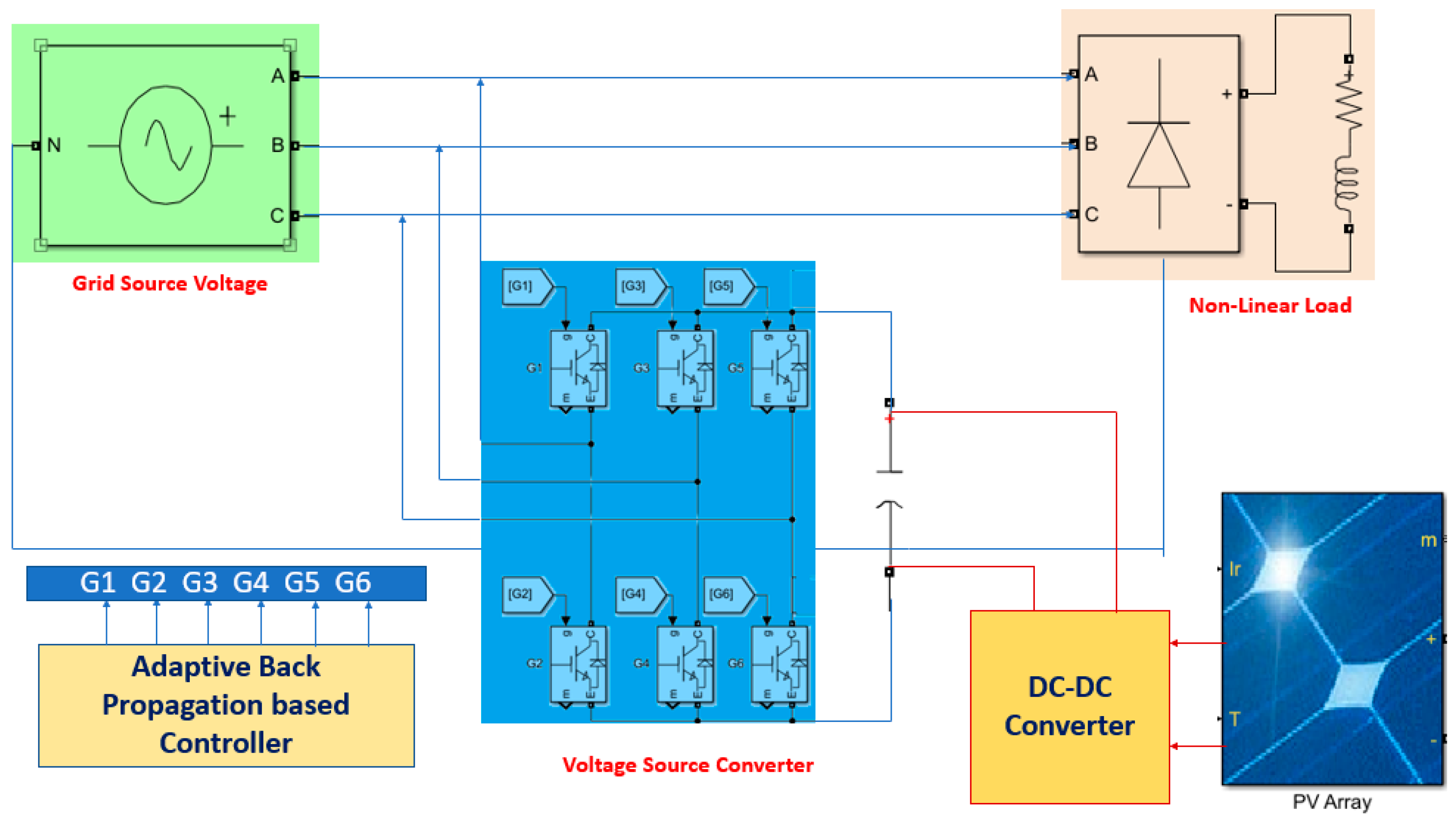
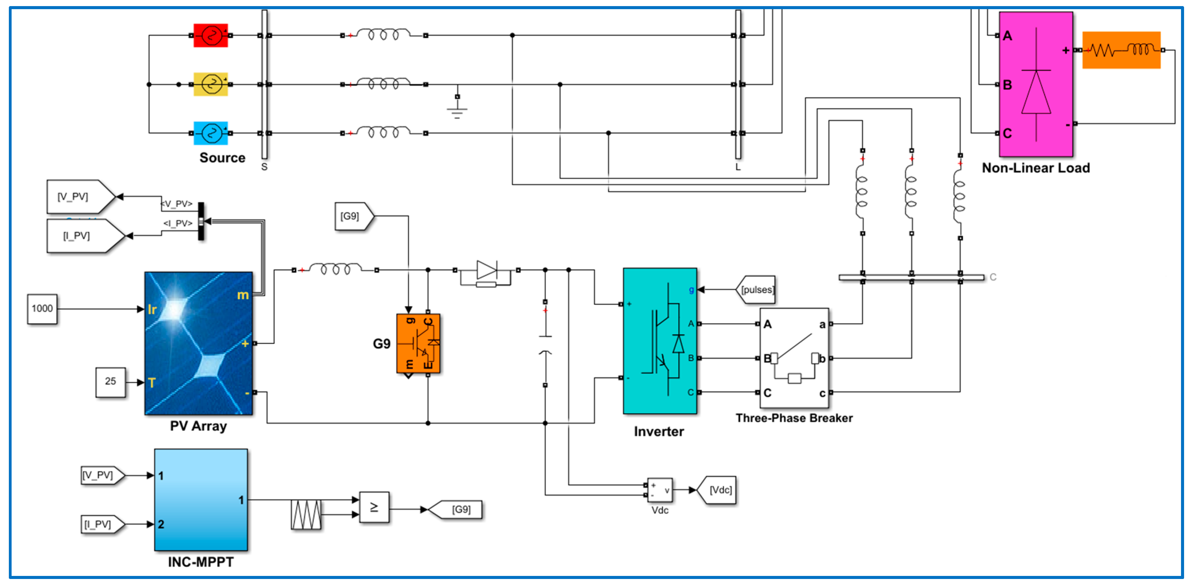
2. System Description
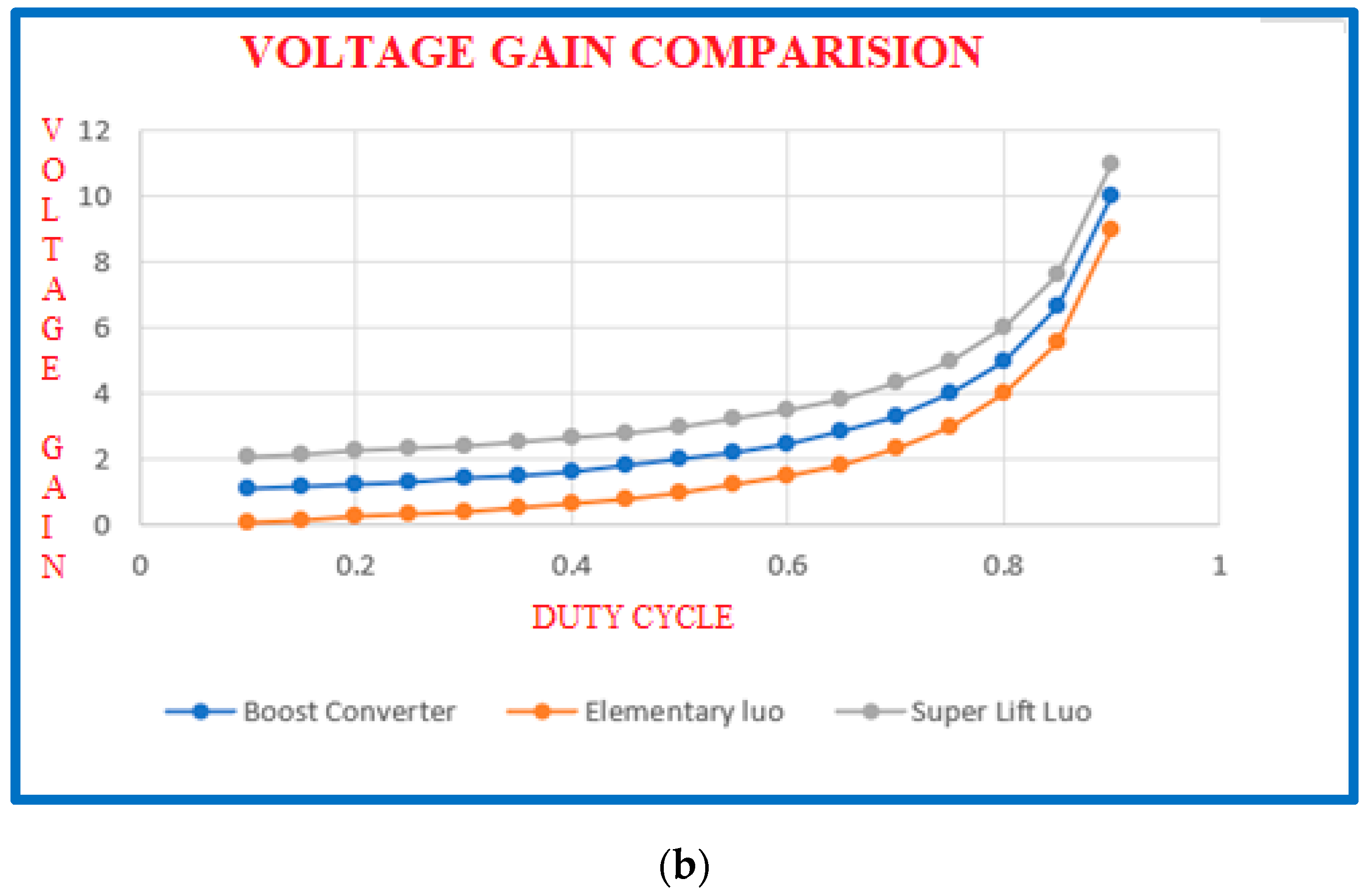
3. DC Link Voltage of the VSC from the Solar PV System
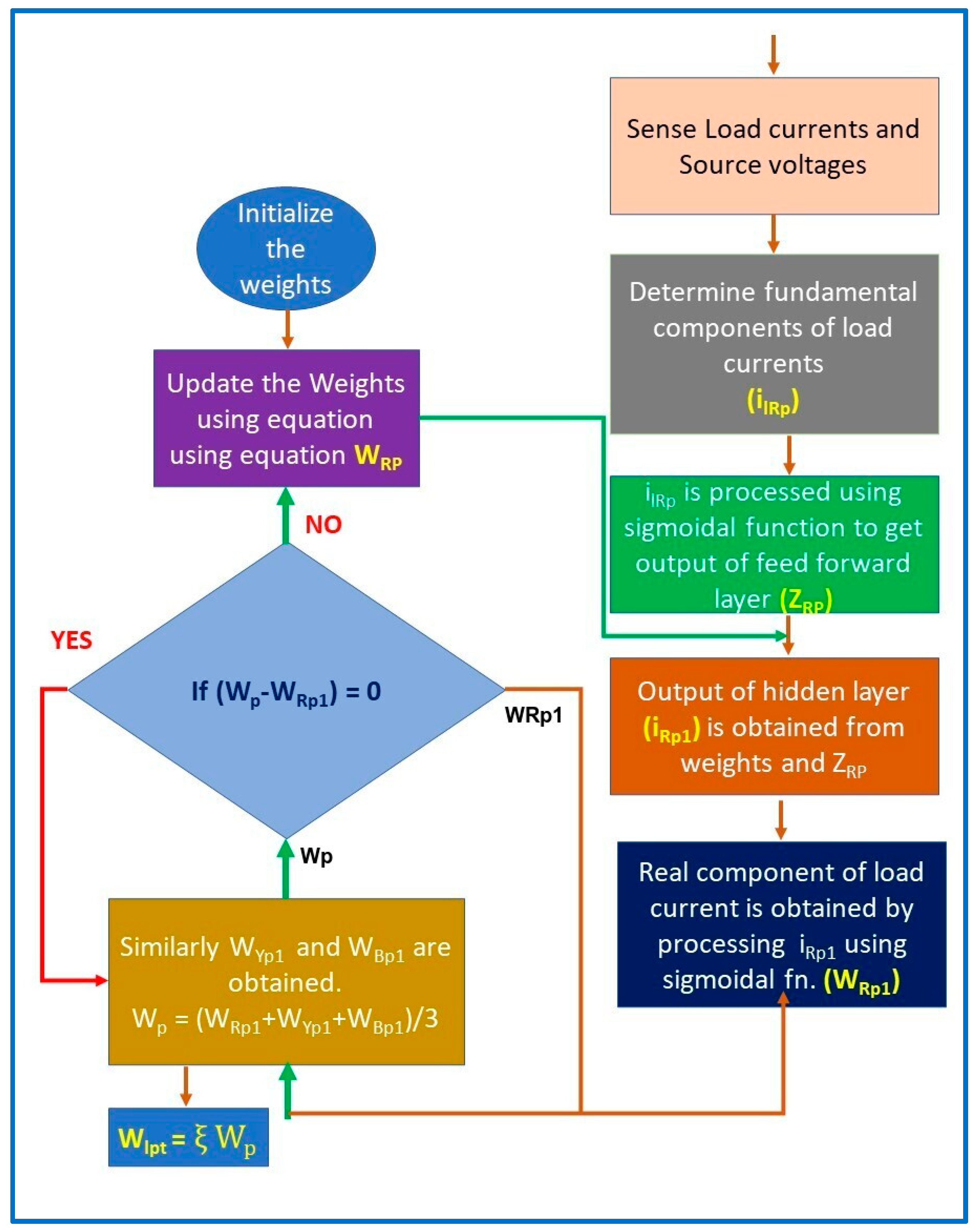
4. Proposed ANN Model to Control Grid-Interactive VSC
- No redundancy as there is only one update at a time;
- It learns online, so it is faster than offline learning;
- Backpropagation is the appropriate method for both offline and online learning.
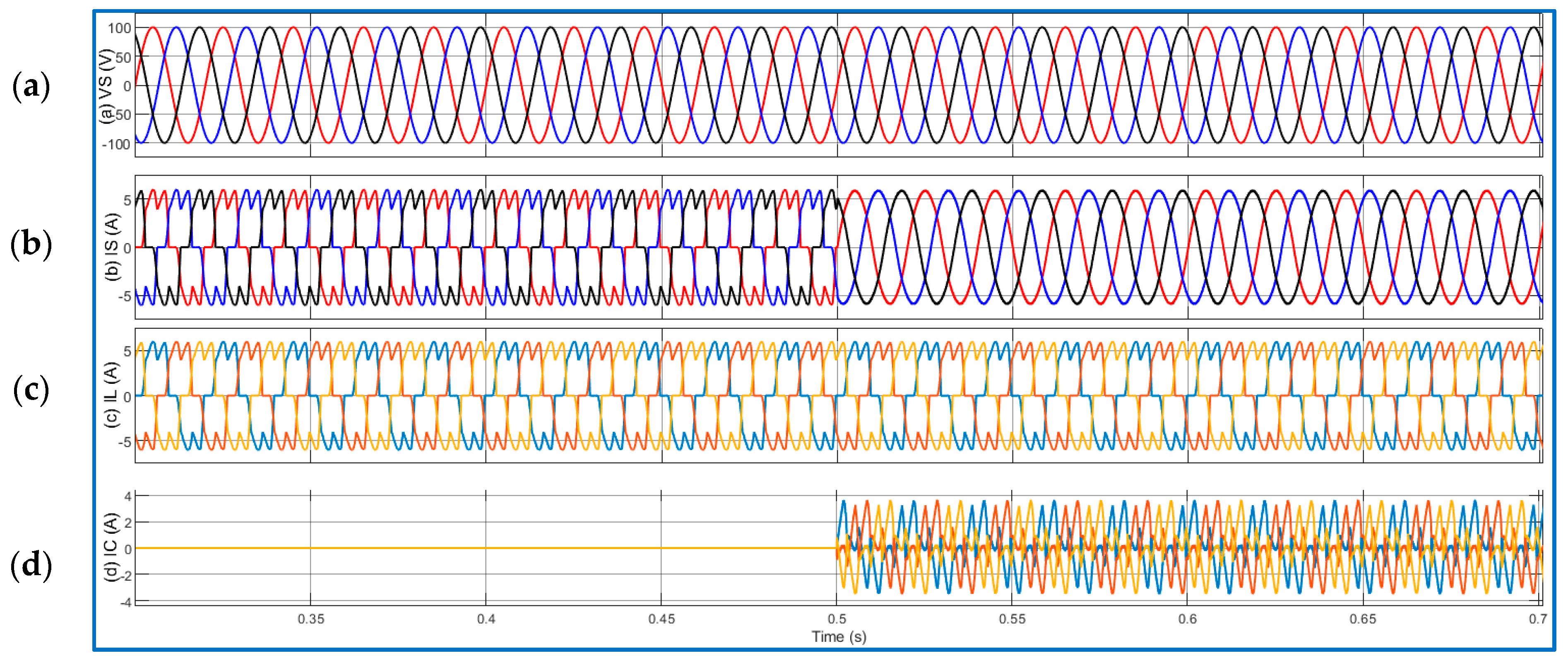
5. Results and Discussion
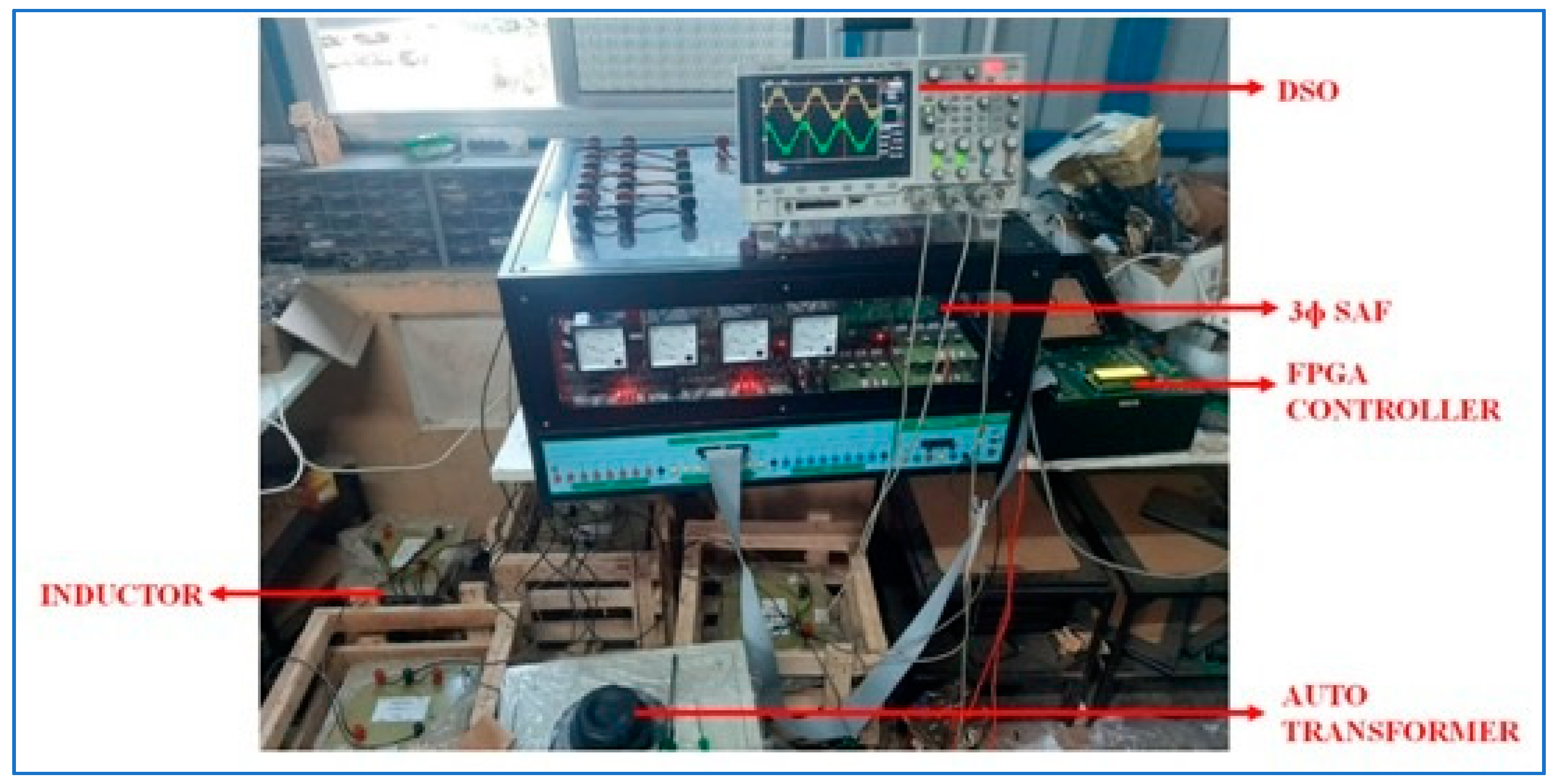
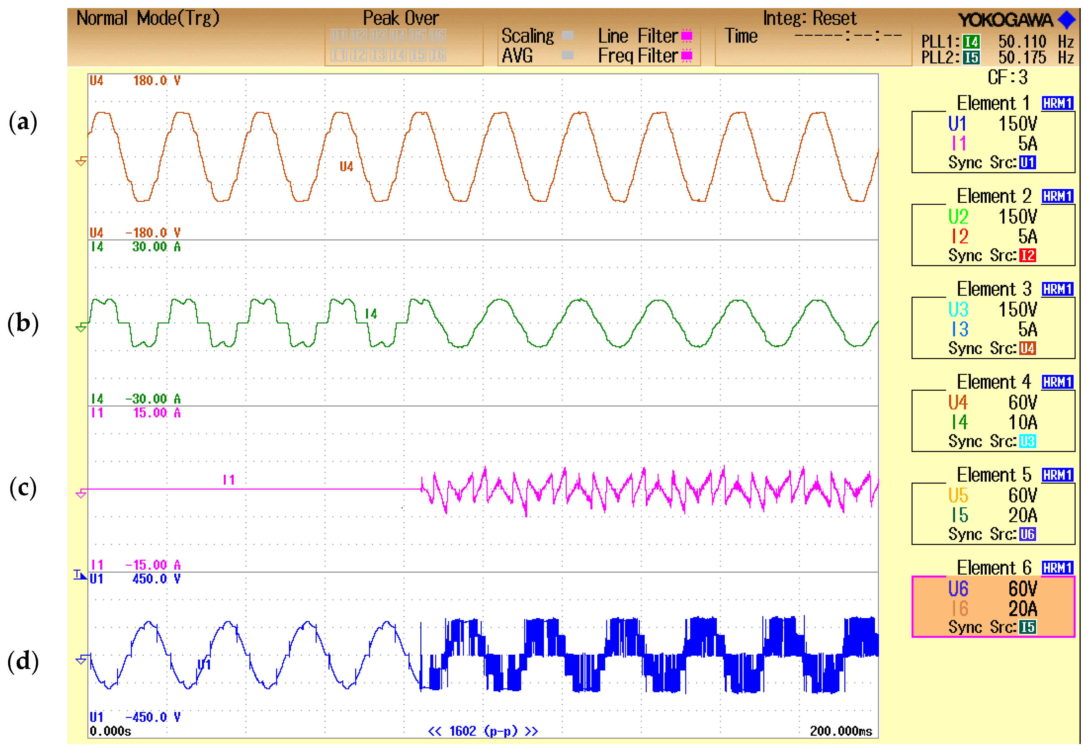
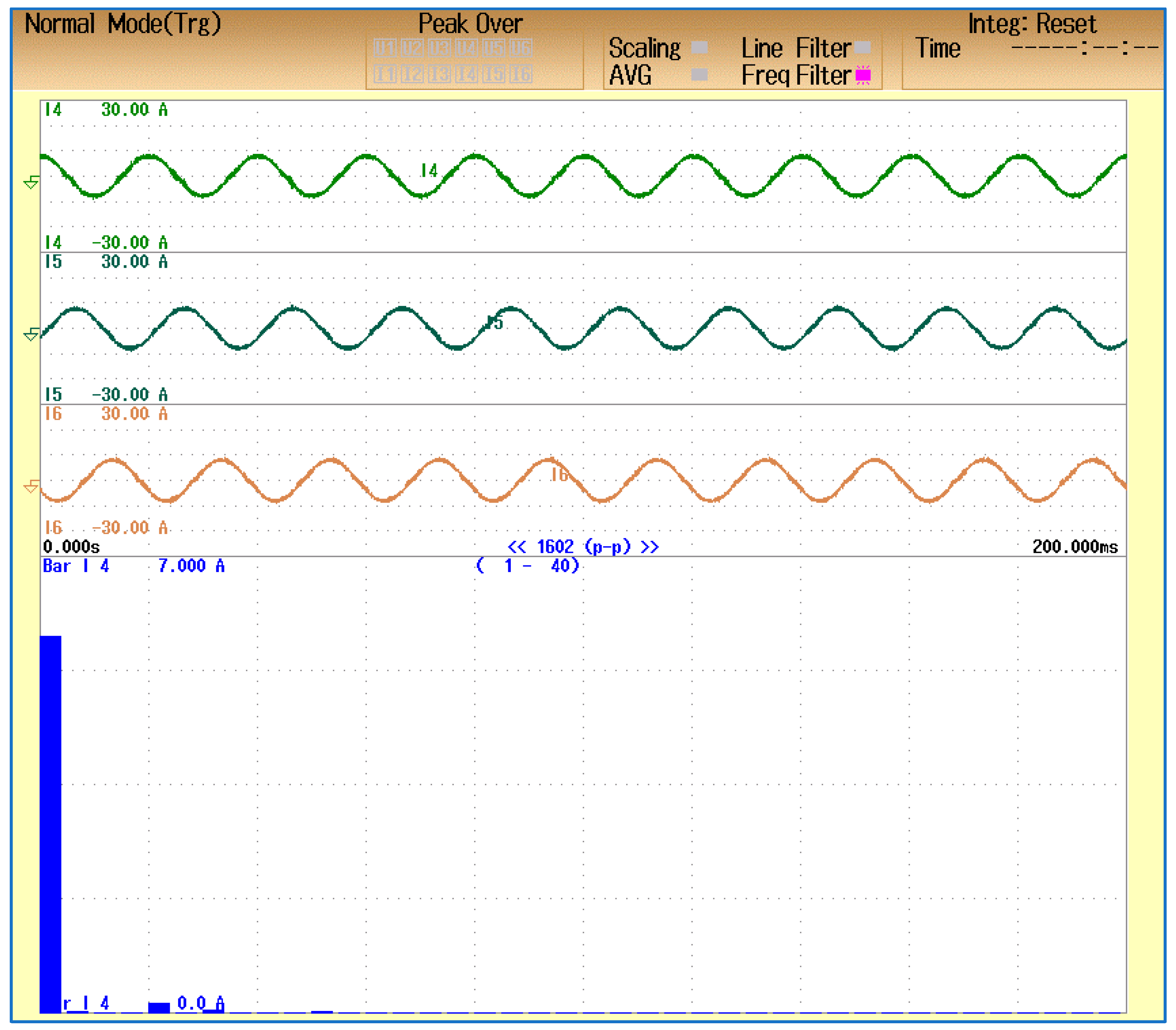
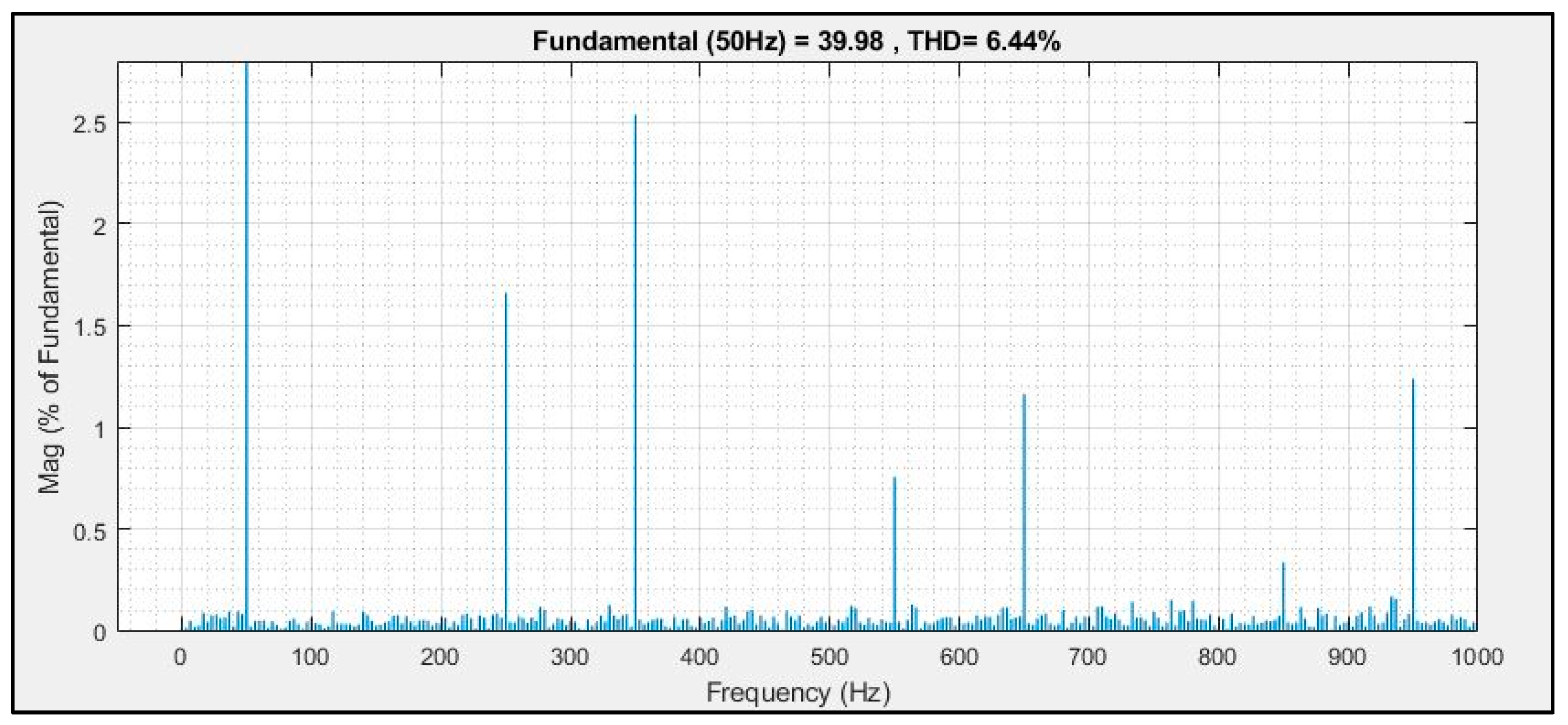
Hardware Implementation: Balanced Non-Linear Load
6. Conclusions
Author Contributions
Funding
Conflicts of Interest
References
- Ritchie, H.; Roser, M. Energy. Published online at OurWorldInData.org. Available online: https://ourworldindata.org/grapher/solar-energy-consumption (accessed on 13 September 2021).
- Lamnini, S.; Kadar, P. Survey on perspectives of PV technology and their applications. In Proceedings of the 2017 IEEE 15th International Symposium on Applied Machine Intelligence and Informatics (SAMI), Herl’any, Slovakia, 26–28 January 2017; IEEE: Piscataway, NJ, USA, 2017; pp. 000503–000510. [Google Scholar]
- Available online: https://mnre.gov.in/solar/current-status (accessed on 31 March 2021).
- Bouzid, A.M.; Guerrero, J.M.; Cheriti, A.; Bouhamida, M.; Sicard, P.; Benghanem, M. A survey on control of electric power distributed generation systems for microgrid applications. Renew. Sustain. Energy Rev. 2015, 44, 751–766. [Google Scholar] [CrossRef] [Green Version]
- Kumar, R.; Sahu, B.; Shiva, C.K.; Rajender, B. A control topology for frequency regulation capability in a grid integrated PV system. Arch. Electr. Eng. 2020, 69, 389–401. [Google Scholar]
- Bendib, B.; Belmili, H.; Krim, F. A survey of the most used MPPT methods: Conventional and advanced algorithms applied for photovoltaic systems. Renew. Sustain. Energy Rev. 2015, 45, 637–648. [Google Scholar] [CrossRef]
- Shayeghi, H.; Shahryari, E.; Moradzadeh, M.; Siano, P. A Survey on Microgrid Energy Management Considering Flexible Energy Sources. Energies 2019, 12, 2156. [Google Scholar] [CrossRef] [Green Version]
- Nejabatkhah, F.; Li, Y.W.; Tian, H. Power Quality Control of Smart Hybrid AC/DC Microgrids: An Overview. IEEE Access 2019, 7, 52295–52318. [Google Scholar] [CrossRef]
- Bajaj, M.; Singh, A.K. Grid integrated renewable DG systems: A review of power quality challenges and state-of-the-art mitigation techniques. Int. J. Energy Res. 2019, 44, 26–69. [Google Scholar] [CrossRef]
- Gowrishankar, A.; Ramasamy, M. SPV-Based UPQC with Modified Power Angle Control Scheme for the Enhancement of Power Quality. J. Circuits Syst. Comput. 2019, 29, 2050064. [Google Scholar] [CrossRef]
- Lakshmi, G.N.; Jayalaxmi, A.; Veeramsetty, V. Optimal placement of distributed generation using firefly algorithm. In Proceedings of the IOP Conference Series: Materials Science and Engineering, Warangal, India, 9–10 October 2020; IOP Publishing: Bristol, UK, 2020; Volume 981, p. 042060. [Google Scholar]
- Vedik, B.; Naveen, P.; Shiva, C.K. A novel disruption based symbiotic organisms search to solve economic dispatch. Evol. Intell. 2020, 1–36. [Google Scholar] [CrossRef]
- Nandi, M.; Shiva, C.K.; Mukherjee, V. Moth-Flame Algorithm for TCSC-and SMES-Based Controller Design in Automatic Generation Control of a Two-Area Multi-unit Hydro-power System. Iran. J. Sci. Technol. Trans. Electr. Eng. 2019, 44, 1173–1196. [Google Scholar] [CrossRef]
- Mudi, J.; Shiva, C.K.; Mukherjee, V. Multi-verse optimization algorithm for LFC of power system with imposed nonlinearities using three-degree-of-freedom PID controller. Iran. J. Sci. Technol. Trans. Electr. Eng. 2019, 43, 837–856. [Google Scholar] [CrossRef]
- Karri, C.; Durgam, R.; Raghuram, K. Electricity Price Forecasting in Deregulated Power Markets using Wavelet-ANFIS-KHA. In Proceedings of the 2018 International Conference on Computing, Power and Communication Technologies (GUCON), Greater Noida, India, 28–29 September 2018; IEEE: Piscataway, NJ, USA, 2018; pp. 982–987. [Google Scholar] [CrossRef]
- Vemuganti, H.P.; Dharmavarapu, S.; Ganjikunta, S.K.; Suryawanshi, H.M.; Rub, H.A. A Survey on Reduced Switch Count Multilevel Inverters. IEEE Open J. Ind. Electron. Soc. 2021, 2, 80–111. [Google Scholar] [CrossRef]
- Gaur, P.; Mittal, A.P.; Singh, B. Feedforward fuzzy logic control for permanent magnet synchronous motor drive. Int. J. Power Electron. 2009, 1, 363–380. [Google Scholar] [CrossRef]
- Arya, S.R.; Singh, B.; Chandra, A.; Al-Haddad, K. Control of Shunt Custom Power Device Based on Anti-Hebbian Learning Algorithm. In Proceedings of the IECON 2012-38th Annual Conference on IEEE Industrial Electronics Society, Montreal, QC, Canada, 25–28 October 2012; IEEE: Piscataway, NJ, USA, 2012; pp. 1246–1251. [Google Scholar]
- Hsin, H.C.; Li, C.C.; Sun, M.; Sclabassi, R.J. An adaptive training algorithm for back-propagation neural networks. IEEE Trans. Syst. Man Cybern. 1995, 25, 512–514. [Google Scholar] [CrossRef]
- Janpong, S.; Areerak, K.L.; Areerak, K.N. A literature survey of neural network applications for shunt active power filters. J. World Acad. Sci. Eng. Technol. 2011, 60, 392–398. [Google Scholar]
- Petrík, T.; Daneček, M.; Uhlíř, I.; Poulek, V.; Libra, M. Distribution Grid Stability—Influence of Inertia Moment of Synchronous Machines. Appl. Sci. 2020, 10, 9075. [Google Scholar] [CrossRef]


| Source Parameters | Load Parameters | Inverter Parameters | Controller Parameters | DC-DC Converter Parameters |
|---|---|---|---|---|
| VS = 100 V P-P Fs = 50 Hz Solar Panel 1 Soltech 1STH-215-P Parallel-10 Series-7 Voc = 36.3 V Isc = 7.84 A Max Power = 15 KW | Balanced Load 3-Ph Bridge Rectifier R = 15 Ω L = 20 mH | Cdc = 100 µF Vdc = 200 V Coupling Inductors L = 20 mH | Kpdc = 0.2 Kidc = 1.52 Kpac = 1.8 Kiac = 0.05 Vdc (ref) = 200 V VT (ref) = 120 V Wm = Wm1 = 0.85 α = ξ = 1.2 Eta = 0.5 Fs = 5 KHz | L1 = 100 µH C1 = 30 µF C2 = 5000 µF INC MPPT |
| Component Name | Specification Details | |
|---|---|---|
| 01 | Shunt Active Filter (DSTATCOM) | 10 KVA, 1000 V DC Link Voltage, 1800 Micro Farads (Cdc) |
| 02 | Controller | EP4CE6 FPGA Board with Programmer Altera Cyclone IV, programmed using the schematic editor of Quartus software |
| 03 | Coupling Inductance | 0–20 Mh, 10 A with tapings |
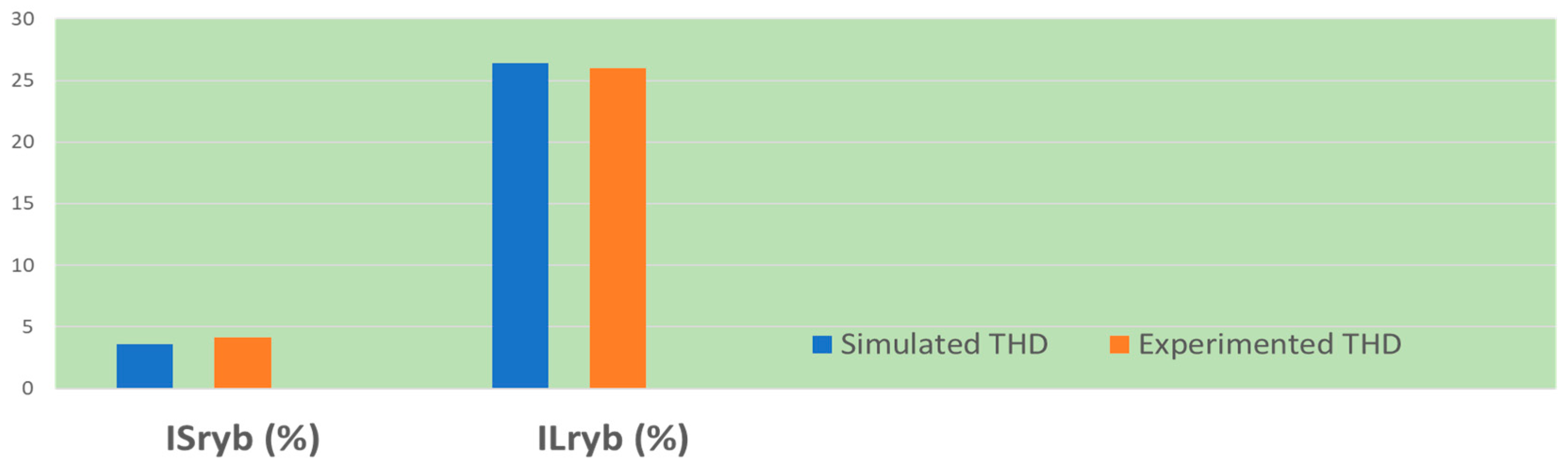
| Parameters/Signals | FFT Analysis of Simulated Performance | FFT Analysis of Experimental Performance |
|---|---|---|
| THD of ISryb (%) | 3.7 | 4.1 |
| THD of ILryb (%) | 26.4 | 25.9 |
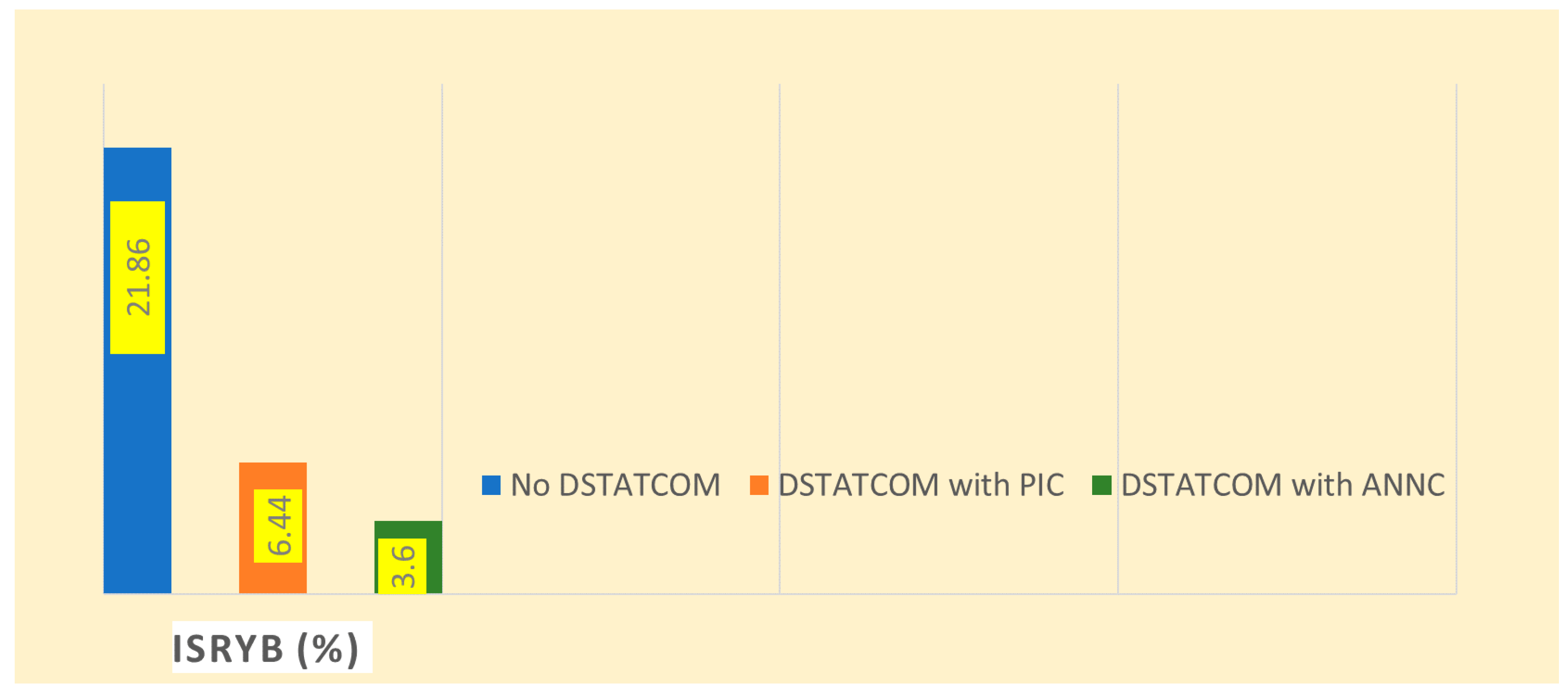
| Parameters/Signals | Without DSTATCOM | DSTATCOM with PI Controller | DSTATCOM with ANN Controller |
|---|---|---|---|
| THD of ISryb (%) | 21.8 | 6.4 | 3.6 |
Publisher’s Note: MDPI stays neutral with regard to jurisdictional claims in published maps and institutional affiliations. |
© 2021 by the authors. Licensee MDPI, Basel, Switzerland. This article is an open access article distributed under the terms and conditions of the Creative Commons Attribution (CC BY) license (https://creativecommons.org/licenses/by/4.0/).
Share and Cite
Irfan, M.M.; Malaji, S.; Patsa, C.; Rangarajan, S.S.; Collins, R.E.; Senjyu, T. Online Learning-Based ANN Controller for a Grid-Interactive Solar PV System. Appl. Sci. 2021, 11, 8712. https://doi.org/10.3390/app11188712
Irfan MM, Malaji S, Patsa C, Rangarajan SS, Collins RE, Senjyu T. Online Learning-Based ANN Controller for a Grid-Interactive Solar PV System. Applied Sciences. 2021; 11(18):8712. https://doi.org/10.3390/app11188712
Chicago/Turabian StyleIrfan, Mohammad Mujahid, Sushama Malaji, Chandarashekhar Patsa, Shriram S. Rangarajan, Randolph E. Collins, and Tomonobu Senjyu. 2021. "Online Learning-Based ANN Controller for a Grid-Interactive Solar PV System" Applied Sciences 11, no. 18: 8712. https://doi.org/10.3390/app11188712
APA StyleIrfan, M. M., Malaji, S., Patsa, C., Rangarajan, S. S., Collins, R. E., & Senjyu, T. (2021). Online Learning-Based ANN Controller for a Grid-Interactive Solar PV System. Applied Sciences, 11(18), 8712. https://doi.org/10.3390/app11188712