Abstract
An on-chip structure consisting of a round-cornered square-shaped (RCSS) resonator as an optical filter is studied via optical experiments, analytical modeling, and numerical techniques. A general coupling model is shown to accurately represent the entire spectral response; the model also provides an understanding of the influence of geometrical and coupling parameters on the resonance characteristics of the RCSS microresonators. The selection of an optimum radius of curvature for rounding off the sharp corners of square microresonators can provide higher quality factors than that of conventional circular resonators. The rotation of the RCSS at the central corner coupling point is also shown to improve the quality factor and remove the minimal phase mismatch requirement and dependency on interaction length. The model results are validated with an electromagnetic finite domain analysis (EMFD) and optical experiments, for which an RCSS on a silicon-on-insulator platform is fabricated. It is shown that the optical performance characteristics (quality factor, transmission ratio, and extinction ratio) of the microresonators are very sensitive to the coupling parameters and must be carefully considered in addition to geometrical length, rotation, and curvature effects. Due to the change in coupling introduced by rotation, the quality factor of the round-cornered square-shaped microresonator can be significantly larger than a circular ring with the same size, thereby establishing RCSS as a competitive alternative to circular microresonators.
1. Introduction
Optical filters and their various types, including ring resonators with high-performance parameters, are among the advanced optical devices that have been used in both industrial and medical applications such as optical components, wavelength division multiplexing (WDM) devices, sensing platforms, among others [1,2,3,4,5,6,7,8]. The two main categories of optical components introduced in the literature are the free-space configurations (appropriate for off-chip devices) and the waveguide-type configurations (appropriate for on-chip devices). In both categories, the filtering mechanism is based on the modulation of the optical characteristics of the incident beam as well as the refractive index (RI) of the layers in slab-guiding structures, resulting in the selective reflection of a narrow band from a wide, specified spectral range and its transmission on both the short and long wavelength sides of this band.
The topmost desired characteristics of optical filters are their tunability, high-quality factor, a low full-width at half-maximum (FWHM) resonance, and small size. To improve the performance of the optical filters, several measures have been implemented. Recently, by manipulating fabrication procedures to reduce scattering, absorption, and intrinsic losses, researchers have demonstrated an ultra-sensitive resonator with a quality factor of up to 422 million [9]. In another study, the coupling loss was lowered by tailoring the directional coupler excitation to the resonator, which experimentally achieved a quality factor of 81 million on the optical resonator platform [10]. Brunetti et al. [11] studied a 1D photonic crystal ring resonator and demonstrated a quality factor of more than at 1.55 m.
In this realm, ring resonators and their variants such as racetrack configurations have good performance parameters and find various applications such as in optical networks and as sensors, for which they have been extensively studied in theory and for practical applications [8,12,13,14,15,16,17]. For racetrack resonators, it was found that the radius of curvature and the length of the coupling region play an essential role in the total optical loss, where a larger radius of curvature reduces the bending loss while increasing the scattering loss. In order to minimize overall loss and improve the quality factor, optimal values for the radius of curvature and the length of the straight coupling section were obtained [18]. However, concerns about short interaction lengths between the circular portion of such resonators and the straight waveguides [19,20] have led researchers to consider polygonal shapes [21,22]. In the absence of sharp corners, the mode changes adiabatically between the radial mode in the curved sections and the normal mode in the straight section [19,23].
In order to address the issues above and to obtain high optical length interaction, a lot of efforts have been made, including the proposition of various structures as well as the use of novel materials. As an example, polygonal microresonators have been introduced due to their ability to provide long interaction lengths and ease the air-gap spacing tolerance [24,25,26]. A longer interaction length and an optimal gap can create a strong modal field overlap of the resonator and the waveguide, which is essential for a strong coupling. However, it was found through a systematic study that the long interaction length between the waveguide and the resonator may make the coupling strength very sensitive to any phase mismatch between the waveguide mode and that of the resonator [20]. On the other hand, the application of polygonal optical microresonators with sharp corners can be limited by severe energy loss at the corners. Panindre et al. [27] incorporated a rounded fillet design into the square resonator, allowing the electromagnetic wave to slowly turn from one side of the square to the other side, thus reducing the optical loss at the sharp corners. When the radius of curvature was varied while maintaining a constant optical path length, they showed that for the single-mode square-shaped microresonators, the quality factors could be significantly increased. At an optimum radius of curvature, it was seen that the quality factor could even be one order higher than that of conventional circular microring resonators. However, the quality factor was found to be lower for several other values of radii of curvature, for which a few possible reasons were provided and discussed [27,28].
In the present work, an optical filter with a round-cornered square-shaped (RCSS) microring resonator is considered and its performance is analyzed. To benchmark the structural and optical characteristics of an RCSS, a coupled-mode theory is employed in the present study and compared to electromagnetic finite domain (EMFD) analysis and experiments.
Previously, the differences in optical losses in the resonator due to the variation of geometric parameters such as the length of straight stretches, the radius of curvature, and coupling length were conjectured to be the main cause of the changes in the optical response; however, the present results indicate that the nature and characteristics of the coupling are also major drivers of the variations. The effects of the radius of curvature and the RCSS rotation on the performance of the filter are numerically investigated and experimentally validated.
2. Coupling Model and Analysis
In 1969, Marcatili [29] presented one of the preliminary coupling models for an integrated optical ring resonator. Since then, waveguide-resonator coupling has been studied for various types of geometries [11,12,30,31,32]. Based on the coupled-mode theory, a mathematical model was developed to analyze the effect of curvature on waveguide modes and to simulate the transmission spectra of the 1D photonic crystal ring resonator [11]. Using the scattering theory, Yariv and co-workers modeled the coupling and showed that the reflection and transmission properties of the waveguide are primarily influenced by the waveguide-resonator coupling, symmetry and degeneracy of the resonant modes, mode resonant frequency, and cavity-loss [12,30]. Several researchers were able to achieve optimum quality factor and extinction ratio [31,32] just by tuning the coupling parameters between the resonator and the input waveguide.
In the present study, a simple form of an optical filter with a round-cornered square-shaped (RCSS) resonator is used and shown in Figure 1. The optical source from the left-hand side of the structure is coupled with the bus waveguide and excites the electromagnetic wave in the RCSS resonator with a narrow-band resonance, leading to the light filtering. A sharp dip exists in the resonance transmission spectra; hence, a good quality filtering wavelength is obtained in the transmission spectrum.
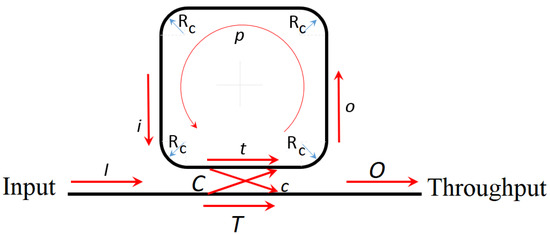
Figure 1.
Schematic of a planar waveguide-coupled RCSS microresonator channel.
The complex output fields O and o are related to the complex input fields I and i through the self-coupling and cross-coupling coefficients T and t, and C and c, respectively. The optical coupling can be expressed as follows [33]:
All the variables in Equation (1) are complex values. Since o is coupled back with the input i, we have:
where p is the propagation along the resonator. From the equation above, we obtain the following:
Tracking the energy in the waveguide and the ring resonator gives:
or
where and are the loss variables of the waveguide and the resonator, respectively.
The left side of Equation (5) can also be expanded by using Equation (1), and using complex conjugates to compute absolute values yields the following:
where the variables with an asterisk * denote complex conjugates.
To simplify the result further, the phases and are introduced as:
where and are magnitudes of p and t, respectively. By defining the scaled resonator propagation value and the coupling region transmission value as and , respectively, we get:
where .
The energy transmission ratio (transmissivity) to throughput port using Equation (9) can be expressed as follows:
In a coupling condition when resonance occurs, minimum energy is transmitted through the throughput port, that is:
Similarly, the energy transmitted to the throughput port is maximum when:
The value of the becomes zero if , that is:
If , would become undefined, as seen in Equation (11). However, this would yield the following:
Since , we would get if , which means that there would be no coupling. Thus, is not physically possible.
The transmission at full-width at half-maximum (FWHM) in this configuration is given by:
can also be found in Equation (10):
Defining as the ratio of the (spectral full-width at half-maximum, which is the wavelength spacing at the half level of the resonance intensity peak) to the (the free spectral range or the wavelength spacing between two successive optical intensity maxima or minima), together with the help of Equation (18), we have the following:
where is the finesse, a quality measure of the microring, which is the ratio between the FSR and the FWHM. High finesse devices have a small FWHM, and a strong intensity build-up in the ring when in resonance is thus a measure of the sharpness of resonances relative to their spacing [15,34]. For simplicity, we introduce and .
The extinction ratio can be computed from the equation above, where = 10 log() = 10 log() [31,32]. For an expression for , Equation (21) is rearranged and simplified as follows:
therefore,
where,
From the experimental or numerical simulation results, the steps to compute and are as follows. By noting the observed full-width at half-maximum (FWHM) values, X (=) can be obtained by using Equations (19) and (20). Looking at the observed transmission values at the throughput port, can be found using Equation (21). From the X and values, A can be computed from Equation (24), which gives and for the resonator-waveguide assembly.
3. Optical Experimental Setup
The designed optical rings are fabricated on a silicon-on-insulator platform with a 2 m thick cladding box and a 220 nm thick silicon layer, using the NanoSOI process available at Applied Nanotools Inc, NRC-NANO Building, 11,421 Saskatchewan Drive NW, Edmonton, Alberta T6G 2M9 Canada [35]. This process is based on direct-write 100 keV electron beam lithography technology (EBL), in which hydrogen silsesquioxane (HSQ) resists and an anisotropic ICP-RIE etch process with chlorine is used. Through the plasma-enhanced chemical vapor deposition (PECVD) process, and with tetraethyl orthosilicate (TEOS) at 300 C as base, a 1 m oxide cladding was deposited on top. As a final step, 150 × 150 m oxide windows were etched away to expose each of the devices to air. A scanning electron microscopy (SEM) image of the fabricated RCSS is shown in Figure 2.
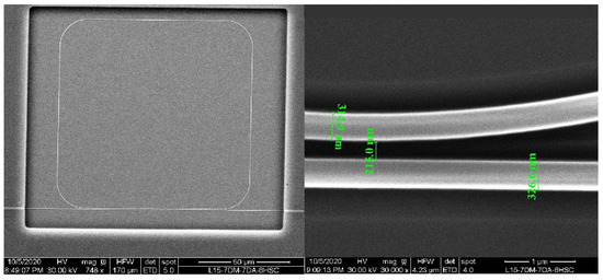
Figure 2.
Scanning electron microscopy (SEM) image of the fabricated RCSS ( = 15 m) microresonator for optical experiments.
The experimental setup is built with a tunable Keysight 81600B laser source, emitting light in the O-band combined with an electronic polarizer, which is used to select and maintain TE and TM polarizations. Single-mode lensed fibers are used to butt-couple the light into the SiPh chip and to collect it at the throughput port of the device. In order to improve the coupling efficiency, edge strip couplers, tapered from 18 nm to the desired waveguide width, are designed at the input and output of the chip. At the end, light is detected using a Keysight N7744A optical detector sensor, which can be read through the Keysight N77x viewer software. The schematic figure of the setup is seen in Figure 3.
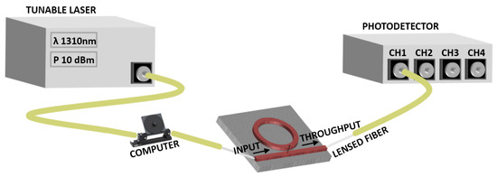
Figure 3.
Schematic configuration of the experimental setup.
For the characterization of the optical transmission response, the light coupled with the device is optimized for the TE and TM polarizations, from an input power of 10 dBm set at the laser source. The data are collected using the Keysight insertion loss software, which sweeps from 1309 nm to 1311 nm wavelengths in order to obtain the O band responses. The step size used for the wavelength was 0.2 pm.
4. Results and Discussion
The performance of the RCSS structures are evaluated by screening several parameters, including finesse and quality factor; the results are discussed below. Note that the quality factor Q provides an absolute measure for the wavelength selectivity of the microring resonator. The quality factor and finesse are related as follows:
4.1. Effects of Propagation () and Transmission ()
The effects of coupling transmission on the transmission characteristics of the RCSS in order to find an optimal set of parameters are investigated. has been increased from 0.6 to 1, while other parameters are kept unchanged. A general parametric response that illustrates the wavelength spectra near resonance is presented in Figure 4 for different values of the resonator propagation value , and the coupling region transmission value . As the resonator becomes lossier (i.e., the value of resonator propagation reduces), the resonance peak becomes broader and the quality factor decreases. Losses in the RCSS resonators have previously been identified to be a result of (i) radial radiation losses at the bends, (ii) the transition losses in the regions where bends and straight segments connect, and (iii) the intrinsic propagation losses per unit length along with the entire travel distance in the microresonator [27].
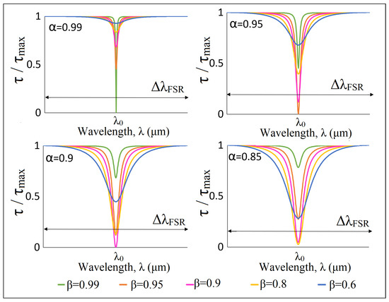
Figure 4.
Effect of transmission () and propagation () on optical response around the resonant wavelength ().
From Figure 4, it can be seen that in addition to the intrinsic losses in the resonator above, the characteristics of the coupling also significantly influence the spectral response of the coupled waveguide-resonator system. The dip in the transmissivity at the throughput port at resonance is a function of the difference between and and is maximized, i.e., the transmissivity ratio is at a minimum (=0) when the values of and are the same (see Equations (11) and (12)). Thus, as shown in Figure 5, to get the maximum spectral transmissivity dip (minimum ) at the throughput port at resonance, the intrinsic propagation property of the resonator should be closest to the coupling transmission , which is a function of the design of the coupling region.
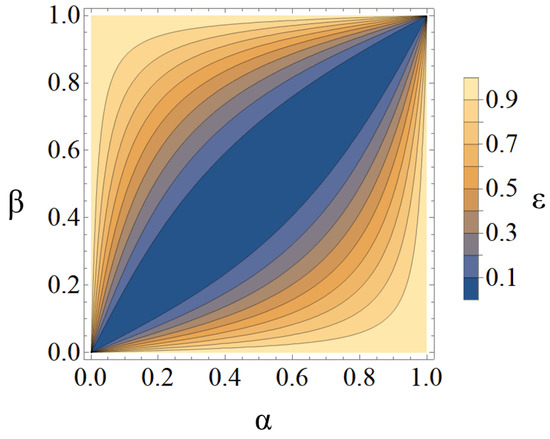
Figure 5.
Variation of the transmission ratio (Equation (21)) at the resonant wavelength () as propagation () and transmission () parameters change for an RCSS microresonator; (ideal) when .
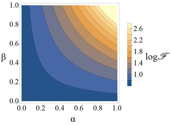
For a given propagation value , higher values of the coupling transmission yield narrower resonance peaks and therefore higher quality factors. This phenomenon is captured in Figure 6 where the finesse is shown to span several orders of magnitude, which is the same trend for the quality factor Q as per Equation (25). The quality factor is a function of the product of and , which is unlike the dependency of throughput port transmissivity on the difference of and . The quality factor Q increases monotonically as a function of . Thus, to obtain the largest throughput port transmissivity dip, i.e., the lowest and the highest extinction ratio, accompanied by the highest quality factor Q, the values of and should be close to unity and as close to each other as possible. This would correspond to a lossless or near-lossless resonator, with a coupling design that gives the highest coupling transmission. Note that the higher the transmission , the lower the coupling c is. However, the value of can never be unity since that would imply , which is only theoretically possible for an isolated microresonator unaffected optically by the waveguide, i.e., not coupled with the waveguide (see Equation (14)). An isolated lossless microresonator would theoretically possess a flat spectral response, except for a delta-function change at resonance, and it is the design of the coupling and its characteristics that introduce the broadened spectral response.
Using the general formulation developed here and discussed in the preceding paragraphs, the specific case of RCSS microresonators [27] is now considered. The system in Figure 1, with geometrical dimensions and operational details (shown in Figure 7 (left)) is examined by numerical analysis. To enable a comparison with previous publications [27,28,36], the width of the input waveguide and the microresonator are kept at 0.35 m, the gap between the microresonator and the input waveguide is 0.2 m, the refractive index of the microresonator and input waveguide is 3.5, and the total optical path length of the microresonator is 400 m (see Figure 7 (left)). The simulation utilizes the electromagnetic frequency domain (EMFD) analysis, which uses the Finite Element Analysis (FEA) to solve the frequency domain form of Maxwell’s equations [37].
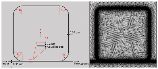
Figure 7.
RCSS m; (left) Schematic with dimensions; (right) Hybrid meshing for FEA analysis.
A hybrid 2D fine meshing technique (a combination of structured and unstructured) is applied, which generates 733,920 domain elements and 30,429 boundary elements in the entire (150 m × 150 m) computational domain (see Figure 7 (right)).
The maximum element size in each domain is equal to , where is the wavelength and n is the refractive index of the particular domain. The boundary condition at the inlet has a 1 V/m electric field in the z-direction (, TE Mode). The scattering boundary condition that makes the boundaries transparent to a scattered wave and an incoming plane wave is used everywhere else [37].
Multiple cases are simulated using 64-bit windows-based Intel Xeon dual CPUs with 3.20 GHz speed and 8 cores each that share 144 GB RAM. On average, each case was simulated for approximately 18 h and 25 min, and the spectral response was numerically generated.
4.2. Effect of the Radius of Curvature in RCSS
From the results of the numerical simulation, the optical coupling parameters and of the coupling model presented in this study can be computed. For the specific case of RCSS microresonators [27], the computed values of and as well as and Q are shown in Figure 8. As the radius of curvature at the corners is increased, with the total optical path length kept constant at 400 m, the propagation value changes significantly, ranging between 0.07 and 0.98. Propagation losses are a cumulative effect of bend losses, transition losses, and intrinsic transmission losses, which fluctuate with the changing radius of the bends, even when the total optical path length remains the same. The quality factor Q also varies considerably. The transmission varies less significantly and stays between 0.83 and 0.99. Due to the constant optical path length, the free spectral range remained the same (∼1.1 nm ± 0.1 nm) for all cases presented in this study.
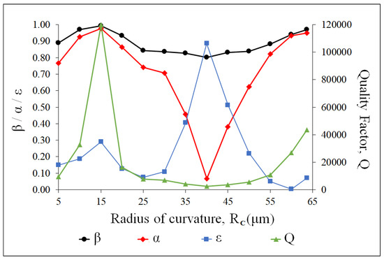
Figure 8.
Optical parameters for a waveguide coupled with RCSS microresonator, TE mode, the total optical path length is 400 m.
The optimal radius of curvature of the RCSS of Panindre and Kumar [27] is 15 m, where the quality factor is the highest (the resonance peak is the narrowest) and the throughput port transmissivity shows a very significant dip at resonance (i.e., Q is the highest, is low, and the extinction ratio is high). These spectral and quality characteristics are desirable in bio-sensing and optical switching applications. This is because both and are high in value (close to unity) and the difference between them is small, allowing the resonance signal at the throughput port to have both high quality (narrow linewidth, ) and a significant transmissivity dip 6 dB). In a similar manner, the least desirable radius of curvature is 40 m, where the extremely small value of coupled with the lowest value of leads to a negligible transmissivity dip dB) and an extremely small quality factor , making the resonance spectral signal indistinguishable from non-resonance regions.
Figure 9 shows the accuracy of the two-parameter transmissivity equation, Equations (10) and (12), with respect to the full spectral signal simulated by the EMFD and the optical experiments for both an RCSS and a ring microresonator. It can be seen that the results from the coupling model and from the EMFD FEA numerical simulation results are virtually identical over the entire free spectral range. These results are also validated by the experimental data, as shown in the figure. Since this is the most important spectral range for applications of resonant microstructures, the coupling model is powerful in describing the optical resonance response. Results from the theoretical model, FEA analysis, and experiments confirm that the round-cornered square-shaped microresonator at an optimum radius of curvature (∼15 m) provides a quality factor (∼) that is better than that of the conventional microring resonator (∼), which is highly desirable for biosensing and other similar applications. Note that the extinction ratio of the conventional ring is 13 dB and that of the RCSS is 6 dB.
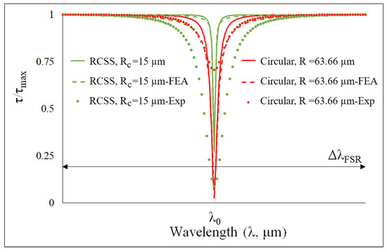
Figure 9.
Comparison between the results obtained from the theoretical modeling, the FEA method, and optical experiments for (i) the RCSS microresonator with the optimal radius of curvature m (green) and (ii) the circular microring resonator (radius 63.66 m), keeping the optical path length at 400 m (red), TE mode.
4.3. Effect of Rotation in RCSS
Rotating the RCSS microresonator in the coupling region can remove the restrictions imposed by the requirement of a minimal phase mismatch between the resonator mode and the waveguide mode in these resonator systems, as well as its dependency on the interaction length between the resonator and feed waveguide. The preliminary results of Panindre et al. [36] showed that the quality factor of these resonators can be improved by increasing the rotation angle (0–45) of the resonator with respect to the feed waveguide around the coupling point. The analysis also established an approach for achieving different quality factors with the same microresonator just by changing its orientation with respect to the feed waveguide; in some cases, the quality factor was significant.
All RCSS microresonator cases discussed in Section 4.2 and Figure 8 have now been rotated by 45 degrees with respect to the feed waveguide. The corresponding values of and as well as and Q are computed and plotted, as shown in Figure 10. Comparing Figure 8, Figure 9 and Figure 10, it can be observed that both and are close to unity in all cases at a 45-degree rotation, with a radius from = 5 m to 55 m; in contrast, in the case of no-rotation, the values of and varied significantly between zero and unity. This results in a higher quality factor for the rotated RCSS at all curvature radii from 0 to 55 µm (∼) and a consistent lower transmission dip ( between 0 and 0.5, or 5 dB to 13 dB). However, as the radius of curvature further increases to 60 m and 63.66 m (circular ring), the and slightly decrease due to an increase in transmission and propagation losses at every point along the circumference of the resonator, leading to a decrease in the quality factor by an order of magnitude (from ∼ to ∼). As the radius of curvature increases, the length of the straight portions of the RCSS microresonator decreases, eventually transforming it into a microring resonator. The straight portions of the RCSS microresonator minimize the transmission and propagation losses but introduce the dependency on the interaction length between the waveguide and the resonator. By rotating the RCSS microresonator by 45 around the coupling point, this dependency and risk of phase mismatch are eliminated (similar to a circular ring). Therefore, the advantage of minimizing losses due to linear wave propagation along the straight sides is retained, which results in a better quality factor (∼) in comparison to conventional microring resonators (∼).
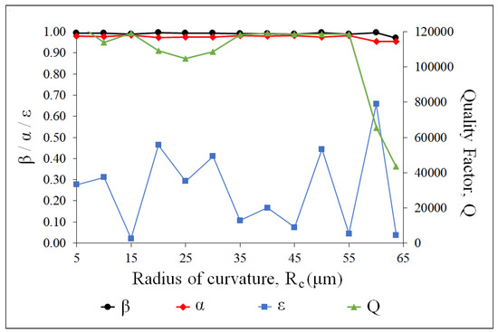
Figure 10.
Optical parameters for the rotated RCSS microresonators of the varying radius of curvature . The rotation angle is 45 with respect to the feed waveguide around the coupling point. The coupling region is in a central corner of the RCSS.
Additionally, the computed values of , , , and Q for the RCSS microresonator ( = 50 m), with varying angles of rotation in relation to the feed waveguide around the coupling point are plotted in Figure 11. When the RCSS is rotated from 0 to 45 degrees, the coupling region changes from straight to curved, and mixed in between. Consistent with the findings [36], as increases from 0 to 45 degrees and the dependency on the interaction length between the RCSS resonator and the feed waveguide decreases, both and steadily increase to reach a value close to unity, with the difference between them continuously decreasing, thus leading to a consistent and significant improvement in the quality factor, which underscores the importance of coupling.
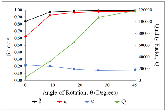
Figure 11.
Optical parameters for an RCSS microresonator ( = 50 m) with varying angles of rotation in relation to the feed waveguide around the coupling point.
By comparing the results of Figure 8 and Figure 10, it can be seen that the same microresonators exhibit different optical characteristics when rotated, i.e., the values of the quality factor and the extinction ratio vary significantly. Rotating changes the coupling characteristics, which demonstrates the importance of coupling to the optical performance. This phenomenon is further investigated for the RCSS microresonator with a radius of curvature of = 50 m with FEA analysis (see Figure 12), whose results have been validated with the data from the optical experiments. The results of both the FEA and the optical experiments demonstrate a significant improvement in the quality factor (from ∼ to ∼) and transmission dip ( increases from 6 dB to 8.2 dB) at resonance, with the rotation of the RCSS resonator (m) around the coupling point. This finding can be envisioned in Figure 13, noting that the corresponding values of the quality factor for the experimental results are lower than those for the FEA analysis due to several experimental and fabrication limitations. For instance, the coupling gap and width of the waveguide and microresonator inputs have experimental uncertainties (a sigma variation of 3.84 nm in width and 1.38 nm in thickness), and may not be the same as the dimensions used for the FEA and theoretical analyses. Additionally, optical microresonators are extremely sensitive to the thermal environment during the optical experiment, both due to the temperature-dependent refractive index of the microresonator and the bulk refractive index of the surrounding medium [7,8,16]. Other experimental uncertainties are the roughness of microresonator surfaces and attenuation/noise at input and output connections. However, the trend of the experimental results on the effect of rotation around the coupling point in RCSS microresonators is in a good agreement with the FEA analysis.
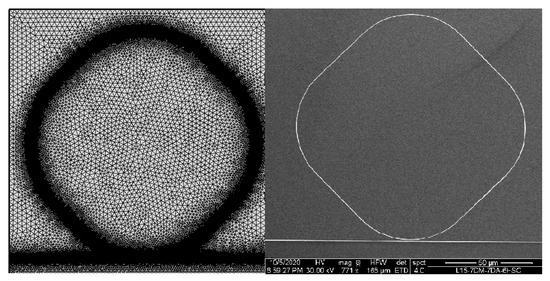
Figure 12.
RCSS ( = 50 m) with 45 rotation in relation to the feed waveguide around the coupling point. (left) Hybrid meshing of the RCSS for FEA analysis; (right) SEM image of the fabricated RCSS for optical experiments.
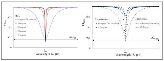
Figure 13.
Comparison of the optical response of the on-chip RCSS device with different angles of rotations: (left) FEA method, (right) optical experiments, and theoretical modeling. Here, = 50 m, and the total optical path length is 400 m, TE mode.
Panindre and Kumar [27] showed that by changing the radius of curvature of the round-cornered square-shaped (RCSS) microresonator, its quality factor can be varied, and the quality factor can be higher than that of the circular ring microresonator at optimum radius of curvature. The current study establishes that the RCSS microresonator of lower quality [27] can be improved by its rotation to a quality factor better than that of a circular ring. This significant result firmly establishes the RCSS, and by extension other geometries with straight sides and curved corners (e.g., polygons, racetrack), as competitive alternatives to conventional circular microresonators.
5. Conclusions
We applied a coupling model to an on-chip structure consisting of a round-cornered square-shaped (RCSS) resonator as an optical filter. The theoretical relationships established in this study indicate that in addition to intrinsic losses in the resonator, the characteristics of the coupling also significantly influence the resonant spectral response of the coupled waveguide-resonator system. The quality factor and finesse of the microresonators were shown to be functions of both transmission () and resonator propagation () values. Theoretical results provided a good understanding of the influencing parameters, and a simple expression that uses only and to represent the entire spectral response was demonstrated.
It was seen that in order to obtain a high-quality factor and the greatest transmission signal dip at resonance, and should be similar in value and as close to unity as possible. Furthermore, these approaches were used to confirm that the quality factor and transmission dip at resonance improve significantly with the rotation of the RCSS resonator in relation to the waveguide around the coupling point. Additionally, the study also experimentally, theoretically, and numerically validated that the RCSS microresonator, at an optimum radius of curvature and an optimum angle with respect to the input waveguide, provides a significantly better resonance response than the conventional microring resonator. The present analysis can assist in improving the coupling characteristics and optical performance of resonators of polygonal, circular, or any other geometries.
The present study establishes that round-cornered square-shaped (RCSS) microresonators can be competitive alternatives to circular ring microresonators, and that with the proper selection of the radius of curvature and the angle of rotation with respect to the input waveguide, the RCSS can deliver a better quality factor as compared to a circular ring microresonator.
Author Contributions
Conceptualization, P.P. and S.K.; investigation, B.P.; methodology, P.P. and N.S.S.M.; supervision, S.K.; validation, B.P. and M.R.; visualization, N.S.S.M.; writing—original draft, P.P. and N.S.S.M.; writing—review and editing, P.P., N.S.S.M., B.P., M.R. and S.K. All authors have read and agreed to the published version of the manuscript.
Funding
This research was partially funded by the research grant, ADEC Award for Research Excellence (AARE-0073) from the Abu Dhabi Education Council.
Institutional Review Board Statement
Not applicable.
Informed Consent Statement
Not applicable.
Data Availability Statement
The data that support the findings of this study are available from the corresponding author upon reasonable request.
Conflicts of Interest
The authors declare no conflict of interest.
Abbreviations
| RCSS | Round-cornered square-shaped |
| FWHM | Full-width at half-maximum |
| EMFD | Electromagnetic finite domain |
| FEA | Finite element analysis |
| RI | Refractive index |
| FSR | Free spectral range |
References
- Hamzah, H.; Lees, J.; Porch, A. Split ring resonator with optimised sensitivity for microfluidic sensing. Sens. Actuators A Phys. 2018, 276, 1–10. [Google Scholar] [CrossRef]
- Rabus, D.G. Integrated Ring Resonators: The Compendium; Springer Series in Optical Sciences; Springer: Berlin/Heidelberg, Germany, 2007; Available online: https://www.springer.com/de/book/9783540687863 (accessed on 27 November 2020).
- Wei, X.; Panindre, P.; Zhang, Q.; Song, Y.-A. Increasing the detection sensitivity for dna-morpholino hybridization in sub-nanomolar regime by enhancing the surface ion conductance of pedot:pss membrane in a microchannel. ACS Sens. 2016, 1, 862–865. [Google Scholar] [CrossRef]
- Krasnokutska, I.; Tambasco, J.-L.J.; Peruzzo, A. Tunable large free spectral range microring resonators in lithium niobate on insulator. Sci. Rep. 2019, 9, 11086. [Google Scholar] [CrossRef] [PubMed] [Green Version]
- Steglich, P.; Hülsemann, M.; Dietzel, B.; Mai, A. Optical Biosensors Based on Silicon-On-Insulator Ring Resonators: A Review. Molecules 2019, 24, 519. [Google Scholar] [CrossRef] [Green Version]
- Henriksson, A.; Kasper, L.; Jäger, M.; Neubauer, P.; Birkholz, M. An approach to ring resonator biosensing assisted by dielectrophoresis: Design, simulation and fabrication. Micromachines 2020, 11, 9543. [Google Scholar] [CrossRef]
- Panindre, P. Label-Free Optical Sensing of a Single Exosome in a Microfluidic Chip. Ph.D. Thesis, Polytechnic Institute of New York University, Brooklyn, NY, USA, 2016. [Google Scholar]
- Mousavi, N.S.S.; Panindre, P.; Kumar, S. Design Optimization of a Single-Mode Microring Resonator for Label-Free Detection of Biomarkers within a Tunable Spectral Range of 2 nm. In Biomedical Imaging and Sensing Conference; Matoba, O., Awatsuji, Y., Luo, Y., Yatagai, T., Aizu, Y., Eds.; SPIE: Yokohama, Japan, 2018. [Google Scholar] [CrossRef]
- Puckett, M.W.; Liu, K.; Chauhan, N.; Zhao, Q.; Jin, N.; Cheng, H.; Wu, J. 422 Million Intrinsic Quality Factor Planar Integrated All-Waveguide Resonator with Sub-MHz Linewidth. Nat. Commun. 2021, 12, 934. [Google Scholar] [CrossRef]
- Spencer, D.T.; Bauters, J.F.; Heck, M.J.R.; Bowers, J.E. Integrated Waveguide Coupled Si3N4 Resonators in the Ultrahigh-Q Regime. Optica 2014, 1, 153. [Google Scholar] [CrossRef] [Green Version]
- Brunetti, G.; Olio, F.D.; Conteduca, D.; Armenise, M.N.; Ciminelli, C. Comprehensive Mathematical Modelling of Ultra-High Q Grating-Assisted Ring Resonators. J. Opt. 2020, 22, 035802. [Google Scholar] [CrossRef]
- Yariv, A. Critical coupling and its control in optical waveguide-ring resonator systems. IEEE Photon. Technol. Lett. 2002, 14, 483–485. [Google Scholar] [CrossRef] [Green Version]
- Heebner, J.; Wong, V.; Schweinsberg, A.; Boyd, R.; Jackson, D. Optical transmission characteristics of fiber ring resonators. IEEE J. Quantum Electron. 2004, 40, 726–730. [Google Scholar] [CrossRef]
- Timotijevic, B.; Gardes, F.; Headley, W.; Reed, G.; Paniccia, M.; Cohen, O.; Hak, D.; Masanovic, G. Multi-stage racetrack resonator filters in silicon-on-insulator. J. Opt. A Pure Appl. Opt. 2006, 8, S473. [Google Scholar] [CrossRef]
- Bogaerts, W.; Heyn, P.D.; Vaerenbergh, T.V.; Vos, K.D.; Selvaraja, S.K.; Claes, T.; Dumon, P.; Bienstman, P.; Thourhout, D.V.; Baets, R. Silicon microring resonators. Laser Photon. Rev. 2012, 6, 47–73. [Google Scholar] [CrossRef]
- Panindre, P.; Kumar, S. Temperature effects on optical resonances in single-mode circular ring and squircular resonators. In Proceedings of the ASME 2017 Heat Transfer Summer Conference, Bellevue, WA, USA, 9–12 July 2017; Volume 2, p. V002T15A001. [Google Scholar] [CrossRef]
- Chen, G.; Jiang, C. Reverse design of microring resonator channel dropping filters. Results Phys. 2020, 19, 103380. [Google Scholar] [CrossRef]
- Kargar, A.; Lee, C. Analysis of racetrack resonators in surface sensing applications. In Proceedings of the PhotonicsGlobal@Singapore, Singapore, 8–11 December 2008; pp. 1–4. [Google Scholar] [CrossRef]
- Chin, M.; Ho, S. Design and modeling of waveguide-coupled single-mode microring resonators. J. Light. Technol. 1998, 16, 1433. [Google Scholar] [CrossRef] [Green Version]
- Soltani, M.; Yegnanarayanan, S.; Li, Q.; Adibi, A. Systematic engineering of waveguide-resonator coupling for silicon microring/microdisk/racetrack resonators: Theory and experiment. IEEE J. Quantum Electron. 2010, 46, 1158–1169. [Google Scholar] [CrossRef]
- Poon, A.; Courvoisier, F.; Chang, R.K. Multimode resonances in square-shaped optical microcavities. Opt. Lett. 2001, 26, 632–634. [Google Scholar] [CrossRef] [PubMed]
- Latiff, A.A.; Rahim, A.; Rafis, H.; Jaafar, A.; Gannapathy, V.R.; Zainuddin, M.N.S. Design high-q square resonator add-drop filter for cwdm application. Aust. J. Basic Appl. Sci. 2013, 7, 364–367. Available online: http://www.ajbasweb.com/old/ajbas/2013/August/364-367.pdf (accessed on 21 September 2020).
- Moon, H.-J.; Sun, S.-P.; Park, G.-W.; Lee, J.-H.; An, K. Whispering gallery mode lasing in a gain-coated square microcavity with round corners. Jpn. J. Appl. Phys. 2003, 42, L652. [Google Scholar] [CrossRef]
- Boriskina, S.V.; Benson, T.M.; Sewell, P.; Nosich, A.I. Optical modes in 2-d imperfect square and triangular microcavities. IEEE J. Quantum Electron. 2005, 41, 857–862. [Google Scholar] [CrossRef] [Green Version]
- Guo, W.-H.; Huang, Y.-Z.; Lu, Q.-Y.; Yu, L.-J. Modes in square resonators. IEEE J. Quantum Electron. 2003, 39, 1563–1566. [Google Scholar] [CrossRef]
- Fong, C.Y.; Poon, A.W. Mode field patterns and preferential mode coupling in planar waveguide-coupled square microcavities. Opt. Express 2003, 11, 2897–2904. [Google Scholar] [CrossRef] [Green Version]
- Panindre, P.; Kumar, S. Effect of rounding corners on optical resonances in single-mode sharp-cornered microresonators. Opt. Lett. 2016, 41, 878–881. [Google Scholar] [CrossRef] [PubMed]
- Panindre, P.; Kumar, S. Closed Loop Microresonators Having Linear Portions and Filleted Corners, Systems Including Such Microresonators, and Methods of Fabricating Such Microresonators. U.S. Patent 10,684,418, 7 November 2019. (Pub. No. US 2019/0339455 A1). Available online: https://www.freepatentsonline.com/y2019/0339455.html (accessed on 14 November 2020).
- Marcatili, E.A.J. Dielectric Rectangular Waveguide and Directional Coupler for Integrated Optics. Bell Syst. Tech. J. 1969, 48, 2071–2102. [Google Scholar] [CrossRef]
- Xu, Y.; Li, Y.; Lee, R.K.; Yariv, A. Scattering-Theory Analysis of Waveguide-Resonator Coupling. Phys. Rev. E 2000, 62, 7389–7404. [Google Scholar] [CrossRef] [PubMed]
- Long, Y.; Wang, J. Optically-Controlled Extinction Ratio and Q-Factor Tunable Silicon Microring Resonators Based on Optical Forces. Sci. Rep. 2015, 4, 5409. [Google Scholar] [CrossRef] [Green Version]
- Sumetsky, M. Optimization of Optical Ring Resonator Devices for Sensing Applications. Opt. Lett. 2007, 32, 2577. [Google Scholar] [CrossRef]
- Lien, S. Chuang, Physics of Photonic Devices, 2nd ed.; John Wiley & Sons: Hoboken, NJ, USA, 2012. [Google Scholar]
- Geuzebroek, D.H.; Driessen, A. Ring-Resonator-Based Wavelength Filters; Springer: Berlin/Heidelberg, Germany, 2006; Volume 123, pp. 341–379. Available online: http://link.springer.com/10.1007/3-540-31770-8_9 (accessed on 22 September 2020).
- Applied Nanotools Inc.: X-ray Optics and Integrated Photonics. Available online: https://www.appliednt.com/ (accessed on 18 August 2020).
- Panindre, P.; Mousavi, N.S.S.; Kumar, S. Effect of rotation on quality factor of single-mode optical resonances in round-cornered square-shaped resonators. In Physics and Simulation of Optoelectronic Devices XXVI; SPIE: San Francisco, CA, USA, 2018; Volume 10526, p. 1052627. [Google Scholar] [CrossRef]
- COMSOL. Comsol Multiphysics User Guide (Version 5.2 a); COMSOL Multiphysics, AB: Stockholm, Sweden, 2016. [Google Scholar]
Publisher’s Note: MDPI stays neutral with regard to jurisdictional claims in published maps and institutional affiliations. |
© 2021 by the authors. Licensee MDPI, Basel, Switzerland. This article is an open access article distributed under the terms and conditions of the Creative Commons Attribution (CC BY) license (https://creativecommons.org/licenses/by/4.0/).