Article

Medical Robotic Bed to Prevent Pressure Sores

1
Ninebell Healthcare, Seongnam-si 13510, Korea
2
Ninebell Ltd., Seongnam-si 13510, Korea
3
School of Electrical Engineering, Kookmin University, Seoul 02707, Korea
*
Author to whom correspondence should be addressed.
Appl. Sci. 2021, 11(18), 8459; https://doi.org/10.3390/app11188459
Submission received: 10 August 2021 / Revised: 8 September 2021 / Accepted: 8 September 2021 / Published: 12 September 2021
(This article belongs to the Special Issue Autonomous Robots for Medical and Social Applications)

Abstract

:
Patients who stay in bed for long periods are prone to pressure sores. Pressure sores cause multiple complications and prolong hospitalization. To prevent pressure sores, the patient’s lying position must be changed continuously so that excessive pressure on any body part does not last long. In this paper, we propose a novel robotic bed to prevent the formation of pressure sores. This robotic bed is composed of multiple segments that are driven independently by brushless direct current motors and that use body pressure information for feedback control. By controlling the movement of the segments on the top of the bed with a fuzzy controller, the patient’s body pressure is kept below the reference value. Moreover, a belt-type body pressure sensor is developed herein by using force-sensing resistor technology to measure the patient’s body pressure. A bed control system composed of the main controller, a teach pendant, motor controllers, and sensors was implemented. Through real experiments, the validity of the proposed robot bed was verified, and it was confirmed that the fuzzy closed-loop controller followed the reference body pressure commands well.

1. Introduction

A significant number of people are receiving long-term care in hospitals and at home for various conditions, including dementia, disability, and other diseases. Caring for such patients requires nurses to possess specialized skills and qualifications in addition to requiring them to perform many simple and labor-intensive tasks. Therefore, patient care is considered a suitable field for the application of robots and artificial intelligence. Patients with severe conditions who need nursing care spend most of their time in bed. Accordingly, several researchers have conducted studies to robotize a bed for such patients. A few researchers have proposed a bed with a robotic arm that can serve patients. Kapusta proposed a robotic system that consists of a bed and a mobile manipulator to provide bedside assistance [1]. Seo et al. presented a robotic bed equipped with two robot arms and an array of pressure sensors attached onto the mattress. They used the pressure distribution on the mattress to estimate the pose of the patient [2]. Studies on beds that control the patient’s posture and sleep quality by measuring the patient’s vital signals have been conducted as well. Loos developed a bed with a multi-sensor mattress pad to detect heart rate, breathing rate, and body orientation [3]. In addition to these studies, a bed that facilitates the lateral rotation or transfer of immobilized patients [4] and a chair bed system [5] have been proposed.
Patients who stay in bed for long periods may develop pressure sores. A pressure sore occurs due to ischemia of the skin and muscles because blood circulation is impaired in parts of the body that are constantly pressed upon. Pressure sores are usually formed in areas of the skin that touch the bed when a person has been bedridden for a long time, and the incidence of pressure sores among patients in intensive care units in Korean hospitals was reported to be 38.3% [6]. Pressure sores cause multiple complications, prolong hospitalization, and increase a patient’s risk of death [7,8,9]. When pressure above a threshold value is applied for more than a certain amount of time, pressure sores are formed. The pressure value at which pressure sores develop varies, but in general, many researchers agree that the threshold is 32 mmHg [10]. To prevent pressure sores, various studies and expert analyses have been conducted, and a number of devices have been developed. These devices can be classified into active devices that control body pressure manually or automatically and passive devices that only relieve body pressure but do not control it. Furthermore, these devices can be classified based on whether they use body pressure information or do not use body pressure information. The most commonly used commercial product is a passive bubble air mattress that is installed on the bed. Sorbed Co. launched an active bed with an integrated pressure sore mattress and a pneumatic pump. The basic concept of this product is similar to that considered in this study, and it controls body pressure by using pneumatic actuators, but it does not use pressure information and is affected by noise issues because of the pneumatic pump [11]. Wellsense, Inc., released the Monitor Alert Protect system, which analyzes body pressure data gathered using sensors embedded in the bed mattress and sounds an alarm when there is a risk of pressure sore formation [12]. Through project INSYDE, the Fraunhofer Institute developed technology to reduce a user’s body pressure by changing the posture of the bed based on measurements of body pressure distribution [13]. Yousefi proposed a bed equipped with multiple air bladders in which the postures are controlled by motors and lead screws to prevent the formation of pressure sores. This bed utilizes body pressure distribution information, but it is impractical because it requires a large number of actuators for bed operation [14]. An air mattress integrated with a pneumatic pump was developed to estimate body pressure by measuring mattress deformation [15]. Misaki et al. proposed an anti-bedsore mattress consisting of multiple air cells and a capacitive pressure sensor. The sensors measure body pressure, and the tension of the air cells is adjusted based on the measured values by using a pneumatic pump [16].
In this study, we propose a novel robotic bed to prevent the formation of pressure sores. This bed consists of multiple independently controlled segments. Each segment is driven using a four-bar mechanism and a brushless direct current (BLDC) motor. The use of an electric motor reduces noise and can eliminate the discomfort caused to patients by pneumatic pump noise in robotic beds that use pneumatic actuators. In addition, in the case of closed-loop control, electric motors offer faster and more precise response characteristics than pneumatic actuators. In the case of open-loop control, excessive pressure may be applied to the body depending on the body type even after controlling. To solve this problem, we implement a closed-loop controller that uses sensors to collect body pressure information. Body pressure is measured using a pressure sensor array composed of force-sensing resistors (FSRs), and the pressure applied to the body is automatically controlled to be lower than the threshold value through fuzzy control. For this purpose, we developed a flexible belt-type pressure sensor. Through actual experiments, the validity of the proposed robot bed is verified. The remainder of this paper is organized as follows: Section 2 presents the details of the proposed bed system, Section 3 presents our experimental results, and Section 4 provides the concluding remarks.

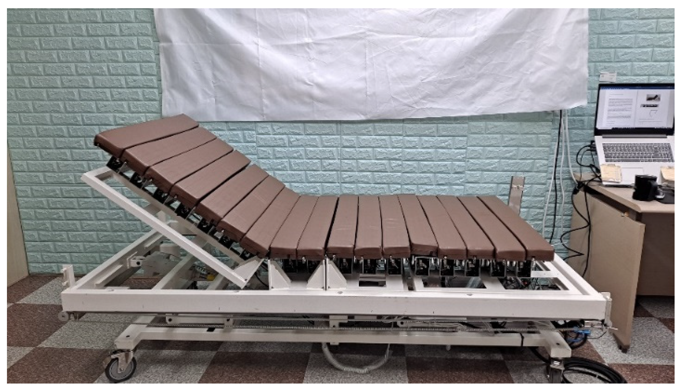
2. Developed Robot Bed System

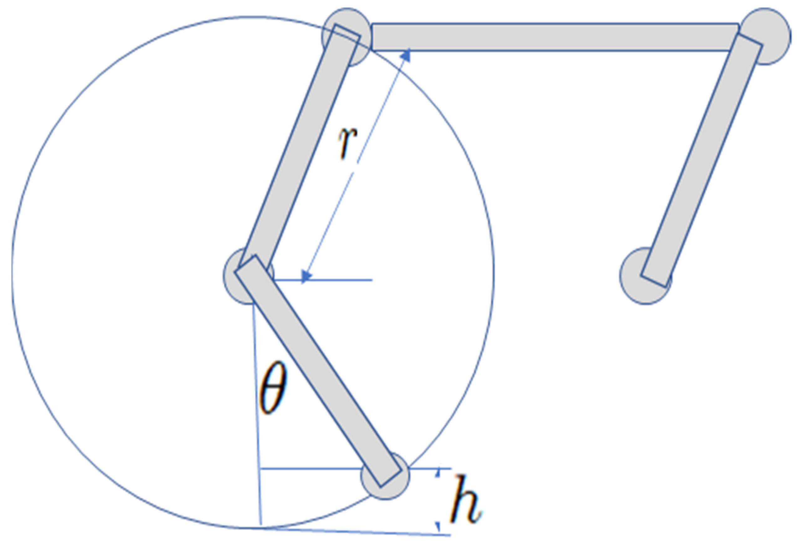
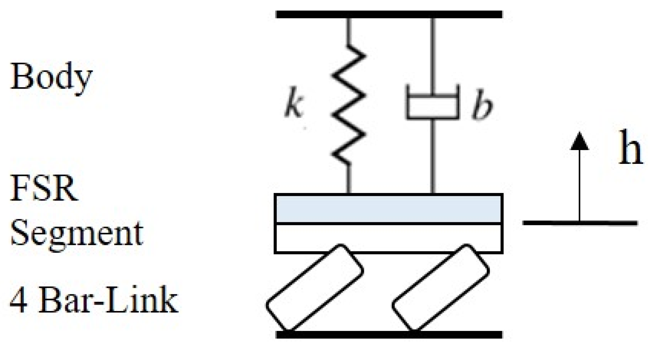
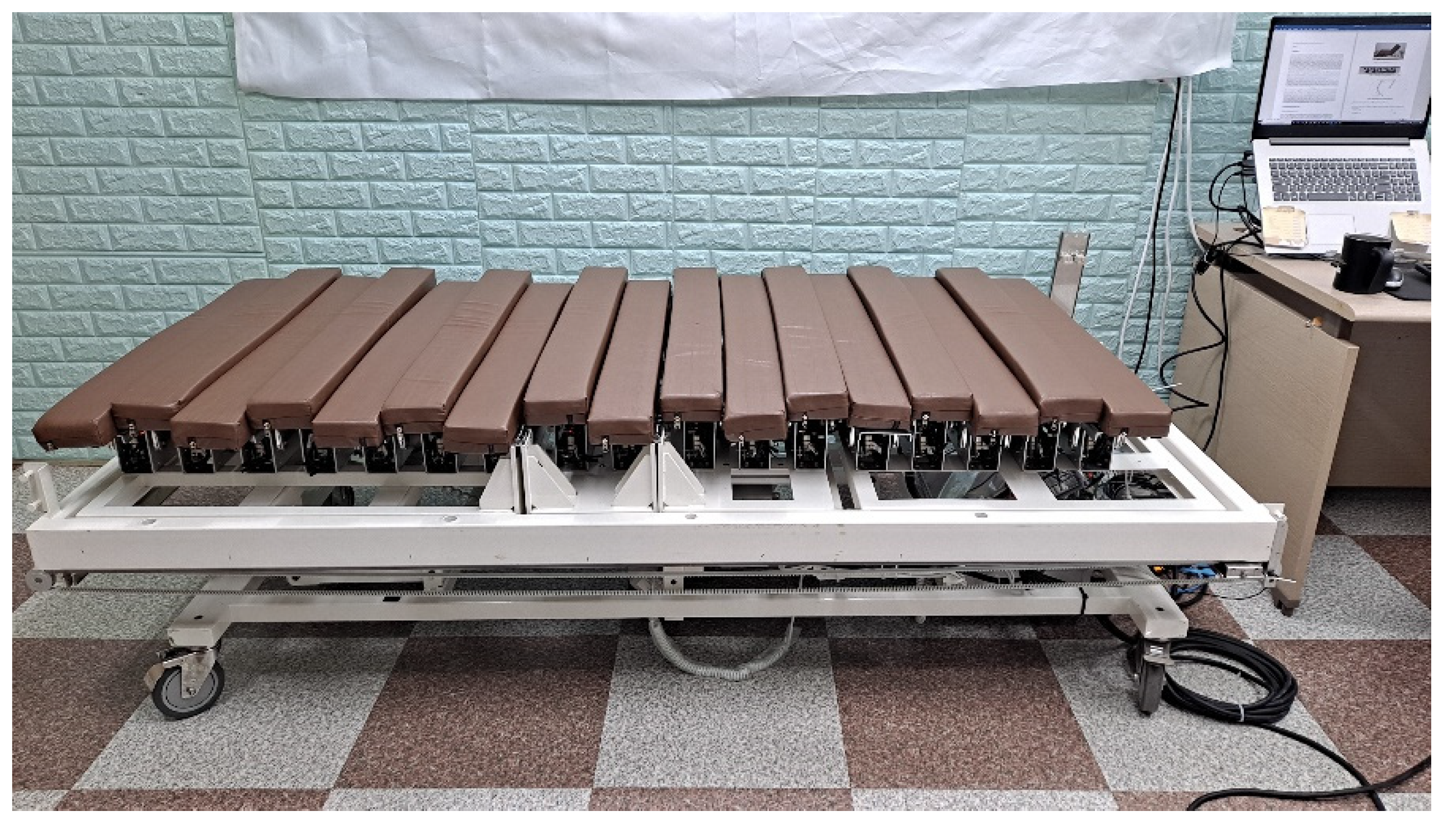
2.1. Robotic Bed Mechanism Design

Figure 1 shows the robotic bed developed in this study. The lower part of the bed is a typical motor-driven medical bed frame. The upper part of the bed is composed of 17 independently controlled segments. As shown in Figure 2, each segment is driven by a four-bar mechanism actuated using a BLDC motor and can move up and down. To solve the phase inversion problem inherent in the four-bar mechanism, a phase offset has been implemented [17].
Figure 3 shows the kinematics of the four-bar mechanism used in each bed segment. Given a link rotation radius r, the height of a segment h and its rotation angle θ can be obtained using Equations (1) and (2), respectively [17].
h = r ( 1 c o s θ )
θ = a c o s ( 1 h r )

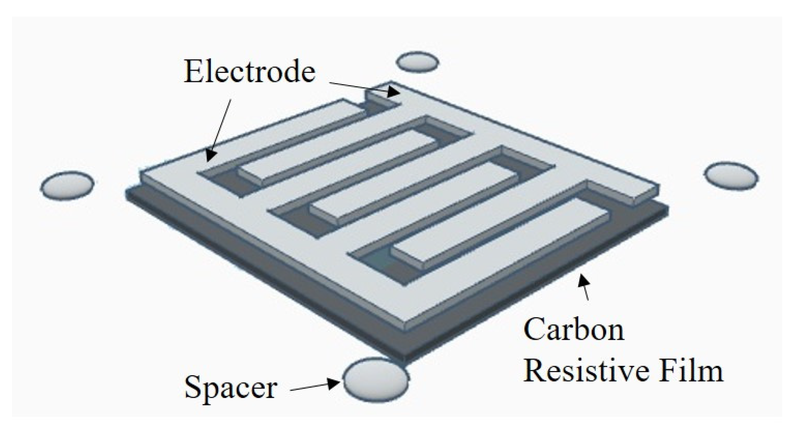
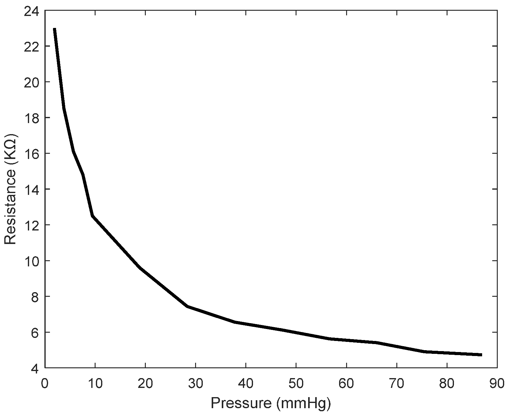
2.2. Pressure Sensor
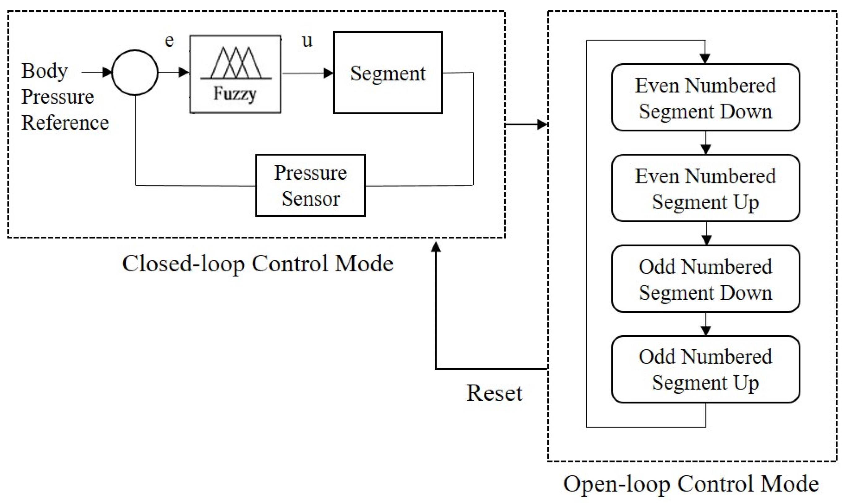
A force/pressure sensor converts a force or pressure into an electrical signal. As each segment of the proposed bed moves relative to the others and pressure sensors are to be installed on the bed, belt-shaped and flexible pressure sensor arrays are needed. With the increasing use of wearable wireless sensor networks, FSRs are increasingly attracting the attention of researchers and practitioners. An FSR is based on the principle that the conductivity of a material changes when it is deformed by an external force. As an FSR is manufactured by printing electrodes on various materials, it is cost-effective to manufacture a large number of FSR arrays, as is required in this study. Each FSR consists of electrodes and a carbon resistive layer, and Figure 4 shows the shape of the FSR electrode used in this study. We printed electrodes on a polyethylene terephthalate (PET) substrate by using conductive silver ink. The resistive layer was fabricated by printing conductive carbon onto a PET film. The measurable pressure range and sensitivity can be tuned by changing the shape of the electrode pattern and the resistance value of the carbon layer. Figure 5 shows the belt-shaped FSR sensor we developed; 10 electrodes are printed on each belt.
One FSR sensor belt is installed on each segment, and in total, 17 sensor belts are used in one bed. Body pressure can be measured at all 170 electrode locations. Pressure is detected using an externally installed resistor distribution circuit and is converted into a digital signal by using an analog-to-digital (A/D) converter in the microcontroller.

2.3. Control Laws

The bed controller was implemented as a dual-mode controller with closed- and open-loop control modes. In the closed-loop control mode, the controller uses body pressure information obtained from the pressure sensor to adjust the pressure acting on the body so that it is lower than the reference value. The same body posture should not be maintained for more than 2 h [6]. If excessive body pressure is applied for an extended period and it is judged that the closed-loop control has failed, the controller enters the open-loop control mode. In some cases, the user can select the open-loop control mode.

2.3.1. Closed-Loop Control Mode

Figure 6 shows the system model used for closed-loop control. The patient’s body is modeled as a spring-damper, where the spring coefficient k and damping coefficient b are not known exactly. The pressure applied to the body is controlled by controlling the segment height h.
The pressure error e i of the ith segment is calculated using Equation (3)
e i = m a x ( p m i p c u ,   0 ) ,   i = 1 , 2 , N
where P c u denotes the reference pressure and N is the number of segments.   P m i is the maximum measured pressure value of segment i: p m i = max p i j ,   j = 1 , 2 , M , where M is the number of pressure sensors in a segment.
We use a fuzzy control algorithm to implement the closed-loop bed controller. Fuzzy controllers are used when the system model parameters are unknown. A fuzzy logic system has three stages: fuzzification, inference, and defuzzification [18]. The body pressure sensors are mounted on a segment, and the height of the segment is controlled using a fuzzy controller. The error e i in Equation (3) is the input to the controller, and the segment height h i in Equation (1) is the output. The input is composed of four fuzzy sets, namely ERR_LOW, ERR_HIGH, ERR_VERYHIGH, and ERR_TOOHIGH. The output is composed of a singleton fuzzy set with the linguistic values LOW, MEDIUM, HIGH, and TOOHIGH. The fuzzy rules are summarized in Table 1.
Using the center-of-gravity defuzzification method, the controller output is determined using Equation (4)
u = i = 1 4 q i μ i ( e ) i = 1 4 μ i ( e )
where μ i ( · ) is a membership function value and q i is constant.

2.3.2. Open-Loop Control Mode

In the open-loop control mode, the segment height is periodically changed to adjust the amount of pressure applied to the body. The open-loop control is repeated at intervals of T1 + T2 (10 min in this study). During T1 (7 min), the segment is in a low position, and during T2 (3 min), the segment remains flat. Odd- and even-numbered segments are operated alternately. Open-loop control ensures that pressure sores do not occur by preventing the application of excessive pressure to the body for more than 2 h at a stretch. A block diagram of the overall control mode is shown in Figure 7.

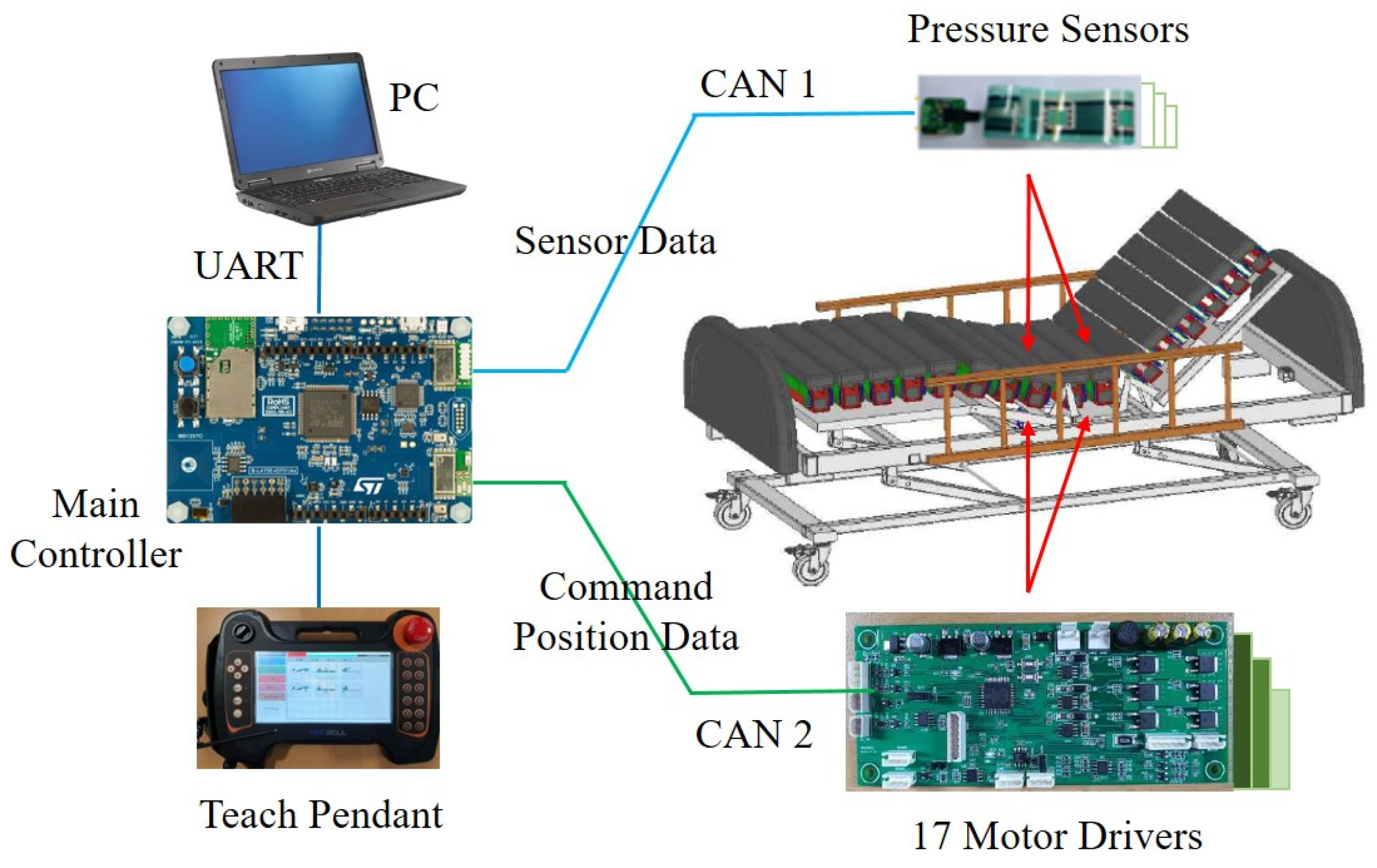
2.4. Integrated System
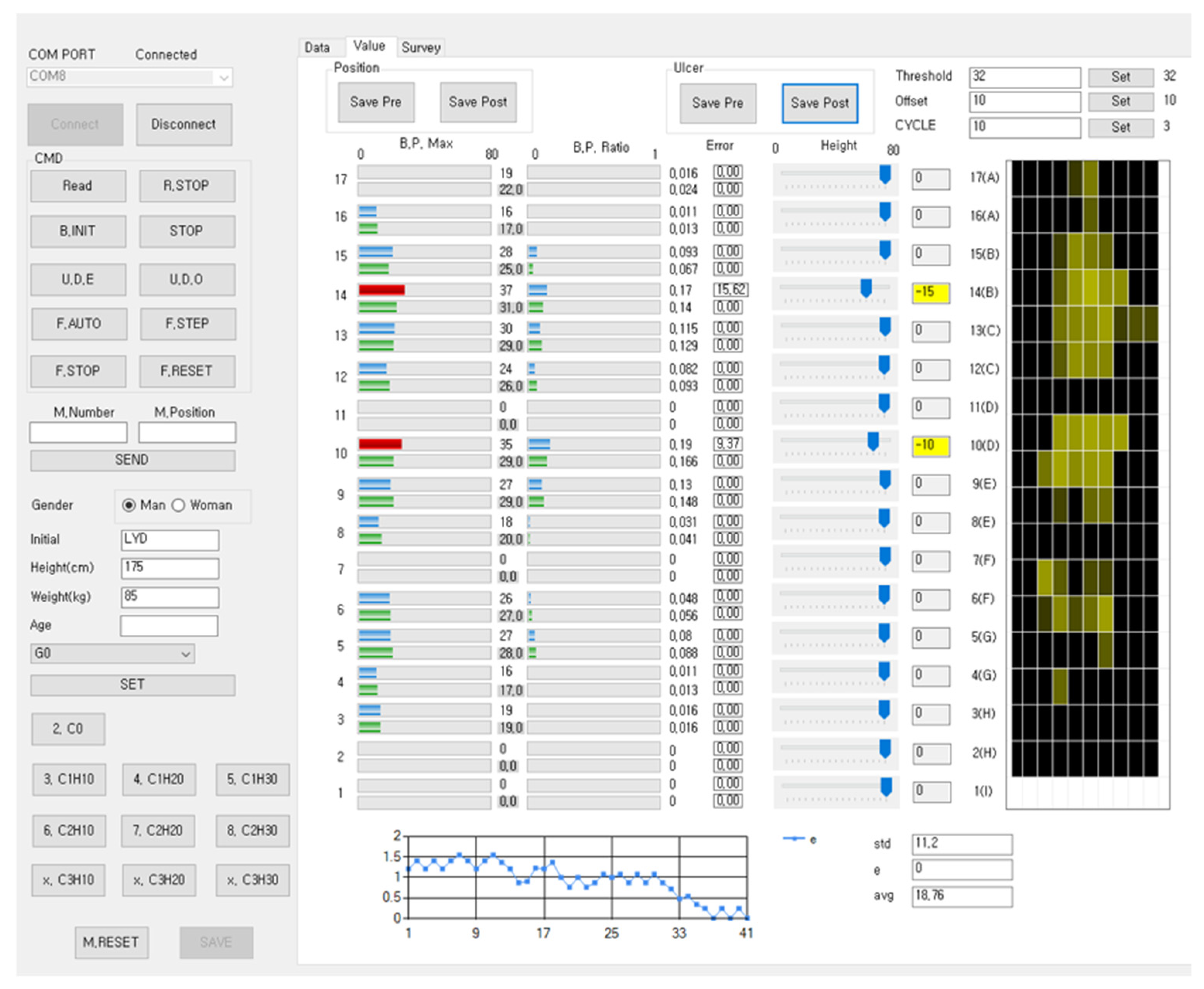
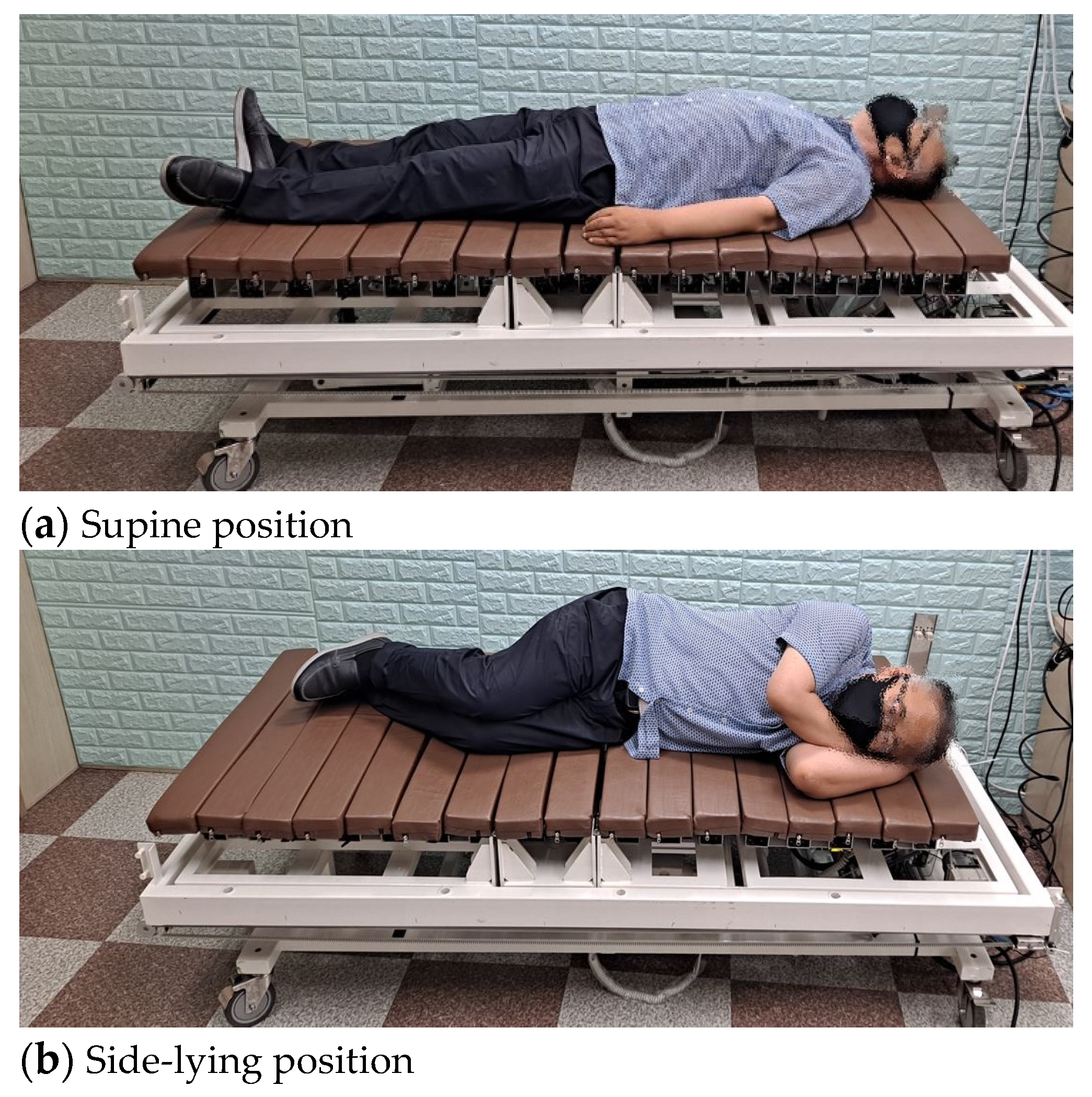
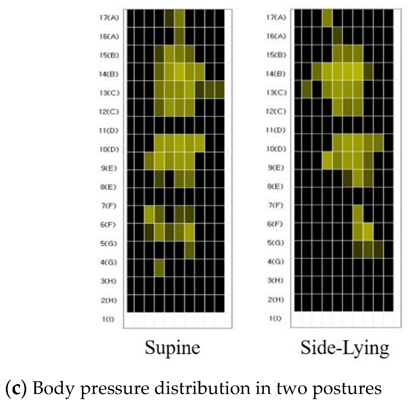
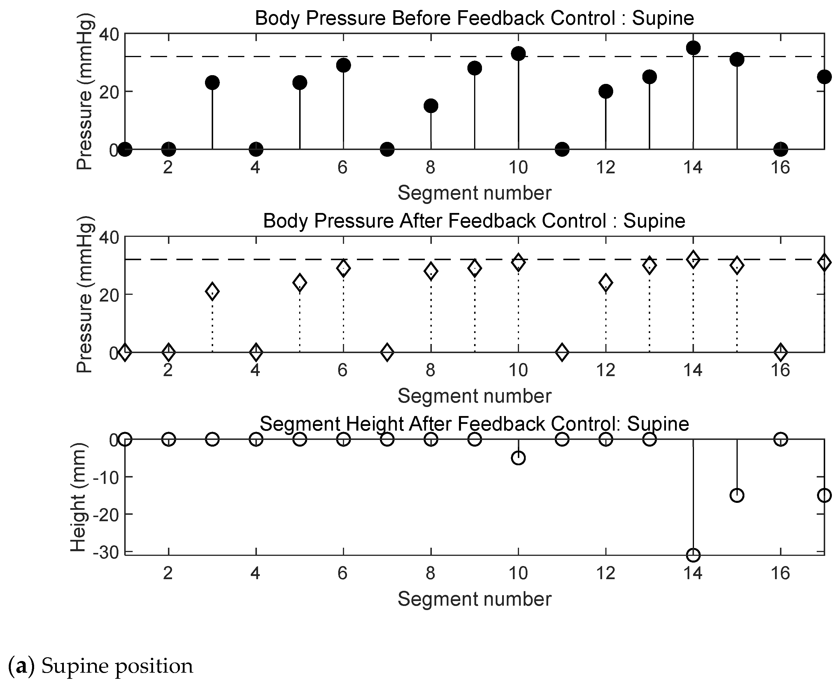
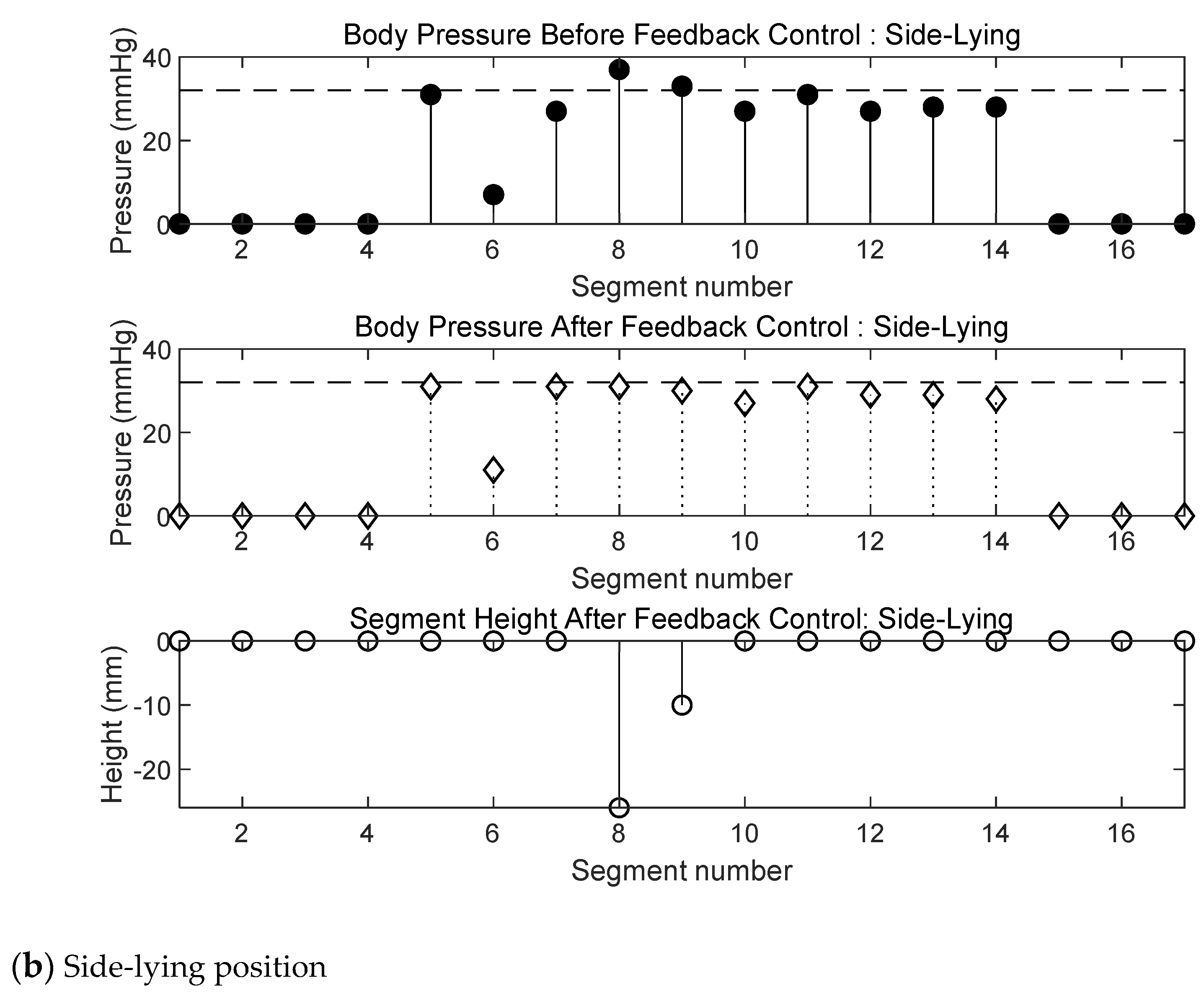
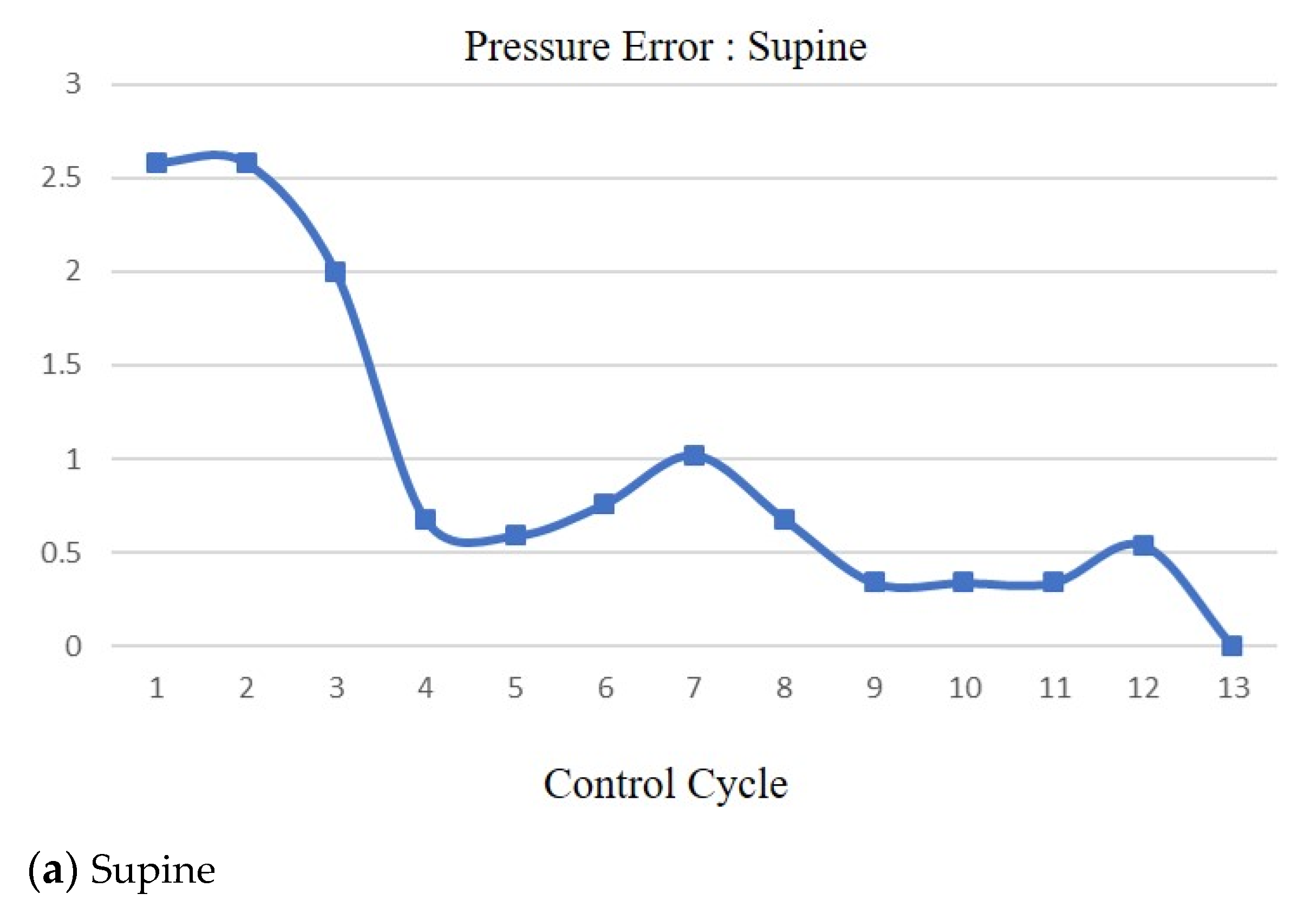
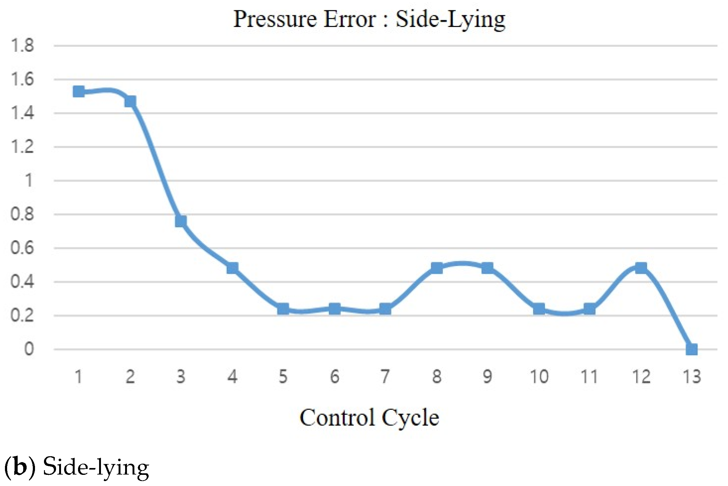
The entire system consists of a robotic bed and a control system, and the bed control system is composed of a main controller, a teach pendant, 17 motor controllers, and 17 FSR sensor interface boards. The sensor data and motor control signal are transmitted through a control area network (CAN). The main controller has two CAN ports, one connected to the motor drivers and the other to the body pressure sensor controllers, as shown in Figure 8. The main controller and the status monitor exchange data through a separate UART (Universal Asynchronous Receiver/Transmitter) serial communication channel [19].

3. Experiments

First, the performance of the newly developed pressure sensor was experimentally verified. As shown in Figure 9, the sensor resistance was measured by increasing the mass of the weight on the FSR sensor. The weight was wrapped in a soft material to simulate human skin. As the pressure increased, the resistance value decreased and then saturated, but the sensor was able to measure pressure values of up to 80 mmHg. FSR sensors have drift and hysteresis characteristics, and these are undesirable [20]. Figure 10 shows that the measured resistance drifts with time for a constant pressure. In this study, sensor drift was not considered, but it should be considered in a future study to realize precise control.
A body pressure control experiment was performed with a test engineer lying on the developed robotic bed. Figure 11 shows the graphical user interface (GUI) of the main control unit. The GUI displays the pressure and height of each segment and the overall body pressure distribution on the screen. Through this GUI, we can set the reference value of body pressure and control the movement of each segment [19]. In the experiment, the subject was lying on the newly developed bed in two positions, supine and side-lying, as shown in Figure 12. Figure 12c shows the body pressure distribution in these two postures. Figure 13 shows the results of closed-loop control experiments conducted for these two postures. The reference value of body pressure Pcu was set to 32 mmHg. When the test subject was lying in the supine position, the body pressure in segments 10 and 14 was higher than the reference value at the beginning, but it was controlled to a value lower than the reference through fuzzy feedback control. The heights of these two segments were changed by −5 mm and −30 mm, respectively (Figure 13a). The following experiment was conducted in the side-lying posture. Before feedback control, the body pressure in segments 8 and 9 was excessive. With feedback control, the body pressure in these two segments was adjusted to 31 mmHg and 30 mmHg, respectively, and they were moved downward by −26 mm and −10 mm.
Figure 14 shows the pressure errors of a segment in the supine and side-lying postures under fuzzy control, where the x-axis represents the number of control iterations. According to the figure, the errors converge at zero. However, if the errors do not converge at zero within the predefined number of iterations, the controller enters the open-loop control mode.
Finally, we tested the open-loop control mode. When entering this control mode, the even- and odd-numbered segments repeat upward and downward motions synchronously, as illustrated in Figure 15. When the control mode is reset, the controller enters the closed-loop control mode again.

4. Discussion

In this study, we proposed a new robotic bed to prevent pressure sores. To prevent pressure sores, it is important to ensure that the pressure applied to the patient’s body is not excessive and does not last for a long time. Thus far, the most commonly used commercial products are bubble air mattresses, which have no function to control body pressure. Although these mattresses may reduce the likelihood of pressure sore formation, the risk of excessive pressure on the body remains, depending on the patient. An active mattress with pneumatic actuators can regulate body pressure, but the pneumatic pump is excessively noisy, which can cause patient discomfort. In this study, we proposed a new medical robotic bed that controls body pressure by using a closed-loop control method. The developed robot bed is composed of 17 independently driven segments and uses body pressure information for feedback control. Each segment is driven by a four-bar mechanism actuated by a BLDC motor. A new belt-shaped pressure sensor array was developed for this bed by using FSR technology. Electrodes and resistors were printed on a PET substrate, and the developed sensor was found to be capable of measuring body pressure values of up to 80 mmHg. The control system was implemented as a multi-mode controller with closed- and open-loop modes. In the closed-loop control mode, the segment height is controlled to ensure that the body pressure is lower than the reference value by using the body pressure sensor information and the fuzzy controller. The reference body pressure was set to 32 mmHg, which is known as the pressure that can cause pressure sores. If excessive body pressure is applied for a long time, the controller switches to the open-loop control mode, in which the positions of the bed segments are periodically and forcefully repositioned to ensure that excessive pressure is not applied to the body for a long period. Body pressure control experiments were performed with the test subject lying on the developed bed. The experiments were conducted for two postures, and in both cases, it was proven that the body pressure error converged at zero and was controlled to a value lower than the reference pressure. Through actual experiments, we verified that the proposed bed is effective at preventing pressure sores. In the future, through long-term clinical trials, we plan to prove the effectiveness of the proposed robotic bed for various body types and patient groups. Moreover, improving patient comfort is another future goal.

Author Contributions

Software, M.S.; conceptualization and project leading, Y.L.; pressure sensor validation, C.M. All authors have read and agreed to the published version of the manuscript.

Funding

This research was supported by the 2020 Technology Development Program (S2926521) funded by the Ministry of SMEs and Startups of Korea.

Institutional Review Board Statement

Not applicable.

Informed Consent Statement

Not applicable.

Conflicts of Interest

The authors declare no conflict of interest.

References

  1. Kapusta, A.S.; Grice, P.M.; Clever, H.M.; Chitalia, Y.; Park, D.; Kemp, C.C. A system for bedside assistance that integrates a robotic bed and a mobile manipulator. PLoS ONE 2019, 14, e0221854. [Google Scholar] [CrossRef] [PubMed]
  2. Seo, K.; Oh, C.; Choi, T.; Lee, J. Bed-type robotic system for the bedridden. In Proceedings of the IEEE/ASME International Conference on Advanced Intelligent Mechatronics, Monterey, CA, USA, 24–28 July 2005; pp. 1170–1175. [Google Scholar] [CrossRef]
  3. Van der Loos, H.M.; Ullrich, N.; Kobayashi, H. Development of Sensate and Robotic Bed Technologies for Vital Signs Monitoring and Sleep Quality Improvement. Auton. Robot. 2003, 15, 67–79. [Google Scholar] [CrossRef]
  4. Wei, C.; Tung, T.; Hsiao, S.; Chen, W.; Chiu, Y.; Tu, K.; Yeh, C.; Chen, K. Hospital Bed with Auxiliary Functions of Lateral Positioning and Transferring for Immobilized Patients. In Proceedings of the IECON, Taipei, Taiwan, 5–8 November 2007; pp. 2991–2995. [Google Scholar] [CrossRef]
  5. Ning, M.; Ren, M.; Fan, Q.; Zhang, L. Mechanism design of a robotic chair/bed system for bedridden aged. Adv. Mech. Eng. 2017, 9, 1–8. [Google Scholar] [CrossRef] [Green Version]
  6. Kim, Y. Evaluation of a pressure ulcer risk assessment tool. Korean Acad. Soc. Adult Nurs. 1997, 9, 272–285. [Google Scholar]
  7. Higgins, N. Management of a Pressure Ulcer in the Presence of Arterial Disease and MRSA Infection. Wound Pract. Res. J. Aust. Wound Manag. Assoc. 2008, 16, 166–168. [Google Scholar]
  8. Bennett, G.; Dealey, C.; Posnett, J. The cost of pressure ulcers in the UK. Age Ageing 2004, 33, 230–235. [Google Scholar] [CrossRef] [PubMed] [Green Version]
  9. Russo, C.A.; Steiner, C.; Spector, W. Hospitalizations Related to Pressure Ulcers Among Adults 18 Years and Older, 2006: Statistical Brief #64. In Healthcare Cost and Utilization Project (HCUP) Statistical Briefs; Agency for Healthcare Research and Quality (US): Rockville, MD, USA, 2006. [Google Scholar]
  10. Hahn, M.; Klyscz, T. Synchronous measurement of blood pressure and red blood cell velocity in capillaries of human skin. J. Investig. Dermatol. 1996, 106, 1256–1259. [Google Scholar] [CrossRef] [PubMed] [Green Version]
  11. Soreless Bed. Available online: https://www.youtube.com/watch?v=wh56qajNYR8&feature=youtu.be (accessed on 9 August 2021).
  12. Smart Mattress. Available online: https://www.zdnet.co.kr/view/?no=20130726151317 (accessed on 9 August 2021). (In Korean).
  13. INSYDE. Available online: https://www.iis.fraunhofer.de/en/ff/sse/health/medical-sensors-and-analytics/prod/insyde.html (accessed on 9 August 2021).
  14. Yousefi, R.; Ostadabbas, S.; Faezipour, M.; Nourani, M.; Ng, V.; Tamil, L.; Bowling, A.; Behan, D.; Pompeo, M. A smart bed platform for monitoring & Ulcer prevention. In Proceedings of the International Conference on Biomedical Engineering and Informatics (BMEI), Shanghai, China, 15–17 October 2011; pp. 1362–1366. [Google Scholar] [CrossRef]
  15. Lee, K.-H.; Kwon, Y.-E.; Lee, H.; Lee, Y.; Seo, J.; Kwon, O.; Kang, S.-W.; Lee, D. Active Body Pressure Relief System with Time-of-Flight Optical Pressure Sensors for Pressure Ulcer Prevention. Sensors 2019, 19, 3862. [Google Scholar] [CrossRef] [PubMed] [Green Version]
  16. Misaki, A.; Imanishi, K.; Takasugi, S.; Wada, M.; Fukagawa, S.; Furue, M. Body pressure sensing mattress for bedsore prevention. SEI Tech. Rev. 2014, 78, 95–99. [Google Scholar]
  17. Lee, Y.; Kim, C.; Choi, M. Enhancement of 4 bar parallelogram linkage for a medical bed. J. Converg. Cult. Technol. 2020, 6, 515–520. [Google Scholar] [CrossRef]
  18. Lilly, J. Fuzzy Control and Identification; Wiley: Hoboken, NJ, USA, 2010. [Google Scholar]
  19. Seon, M.; Choi, J.; Lee, Y. Control Technique of a Medical Bed for Ulcer Prevention Equipped with Body Pressure Sensors. J. IIBC 2021, 21, 89–95. [Google Scholar] [CrossRef]
  20. Giovanelli, D.; Farella, E. Force sensing resistor and evaluation of technology for wearable body pressure sensing. J. Sens. 2016, 2016. [Google Scholar] [CrossRef] [Green Version]
Figure 1. The developed medical bed.
Applsci 11 08459 g001
Figure 2. Modified four-bar link mechanism.
Applsci 11 08459 g002
Figure 3. Kinematics of the four-bar link mechanism.
Applsci 11 08459 g003
Figure 4. Structure of the single force-sensing resistor.
Applsci 11 08459 g004
Figure 5. The belt-shaped force-sensing resistor.
Applsci 11 08459 g005
Figure 6. System model for the control.
Applsci 11 08459 g006
Figure 7. Controller bock diagram.
Applsci 11 08459 g007
Figure 8. Structure of the control system.
Applsci 11 08459 g008
Figure 9. Change in resistance.
Applsci 11 08459 g009
Figure 10. Resistance drift.
Applsci 11 08459 g010
Figure 11. GUI screen.
Applsci 11 08459 g011
Figure 12. Two body postures considered in the experiments.
Applsci 11 08459 g012aApplsci 11 08459 g012b
Figure 13. Closed-loop control experiment results.
Applsci 11 08459 g013aApplsci 11 08459 g013b
Figure 14. Fuzzy pressure control performance.
Applsci 11 08459 g014aApplsci 11 08459 g014b
Figure 15. Open-loop control experiment result.
Applsci 11 08459 g015
Table 1. Fuzzy Rules.
RuleIf-Then
R 1 If e is ERR_LOW, then u is LOW
R 2 If e is ERR_HIGH, then u is MEDIUM
R 3 If e is ERR_VERYHIGH, then u is HIGH
R 4 If e is ERR_TOOHIGH, then u is TOOHIGH
Publisher’s Note: MDPI stays neutral with regard to jurisdictional claims in published maps and institutional affiliations.

